Review

Review of Management System and State-of-Charge Estimation Methods for Electric Vehicles

by
Jigar Sarda
1,
Hirva Patel
2,
Yashvi Popat
3,
Kueh Lee Hui
4,* and
Mangal Sain
5,*
1
M. & V. Patel Department of Electrical Engineering, Chandubhai S. Patel Institute of Technology, Charotar University of Science & Technology, Changa 388421, India
2
Department of Information and Communication Technology, School of Technology, Pandit Deendayal Energy University, Gandhinagar 382007, India
3
Computer Engineering, Devang Patel Institute of Advance Technology and Research, Charotar University of Science & Technology, Changa 388421, India
4
Department of Electrical Engineering, Dong-A University, Busan 49236, Republic of Korea
5
Division of Computer & Information Engineering, Jurye-ro, Sasang-gu, Busan 49236, Republic of Korea
*
Authors to whom correspondence should be addressed.
World Electr. Veh. J. 2023, 14(12), 325; https://doi.org/10.3390/wevj14120325
Submission received: 10 October 2023 / Revised: 2 November 2023 / Accepted: 9 November 2023 / Published: 27 November 2023
(This article belongs to the Special Issue Dynamics, Control and Simulation of Electrified Vehicles)

Abstract

:
Energy storage systems (ESSs) are critically important for the future of electric vehicles. Due to the shifting global environment for electrical distribution and consumption, energy storage systems (ESS) are amongst the electrical power system solutions with the fastest growing market share. Any ESS must have the capacity to regulate the modules from the system in the case of abnormal situations as well as the ability to monitor, control, and maximize the performance of one or more battery modules. Such a system is known as a battery management system (BMS). One parameter that is included in the BMS is the state-of-charge (SOC) of the battery. The BMS is used to enhance battery performance while including the necessary safety measures in the system. SOC estimation is a key BMS feature, and precise modelling and state estimation will improve stable operation. This review discusses the current methods used in BEV LIB SOC modelling and estimation. It also efficiently monitors all of the electrical characteristics of a battery-pack system, including the voltage, current, and temperature. The main function of a BMS is to safeguard a battery system for machine electrification and electric propulsion. The major responsibility of the BMS is to guarantee the trustworthiness and safety of the battery cells coupled to create high currents at high voltage levels. This article examines the advancements and difficulties in (i) cutting-edge battery technology and (ii) cutting-edge BMS for electric vehicles (EVs). This article’s main goal is to outline the key characteristics, benefits and drawbacks, and recent technological developments in SOC estimation methods for a battery. The study follows the pertinent industry standards and addresses the functional safety component that concerns BMS. This information and knowledge will be valuable for vehicle manufacturers in the future development of new SOC methods or an improvement in existing ones.

Graphical Abstract

1. Introduction

The worldwide community is now facing significant ramifications, notably global warming and the release of greenhouse gases (GHGs), due to the widespread utilization of petrol and diesel in vehicular operations. This practice results in the annual emission of substantial amounts of carbon dioxide (CO2). In addition, the rising cost of crude oil has resulted in significant setbacks for the car industry, hence emphasizing the need to advance the development of vehicles powered by alternative fuels. The adoption of EVs has garnered significant interest and emerged as a compelling option for scholars and automotive experts to tackle the aforementioned issues. This is mostly owing to the potential attributes of EVs in mitigating greenhouse gas emissions.
An electrical ESS known as a battery has the ability to store an ample quantity of energy for a longer time period. The BMS, which serves as a crucial control component, is used to ensure the operational integrity and safety of a battery-pack system [1,2,3]. The primary purpose of a BMS is battery protection. For the purposes of ageing, cell balance, and safety, each cell must be continuously monitored. In the occurrence of any abnormal situations at the system, BMS ensures that the predefined remedial measures are carried out. Furthermore, because it affects the profile of power consumption, BMS validates the proper technique to manage system temperature. The battery management technologies used in hybrid electric vehicles (HEVs) and EVs have been described in [4]. Concerns and difficulties with the present BMSs are discussed in the study. A crucial job for a BMS is to assess the condition of a battery, including its life, health, and charge. Analysing the most current methodologies for battery state evaluation, probable future issues for BMSs are explored, along with potential remedies. BMS hardware principles were explored in [5] by the authors. This study elaborates on the BMS hardware features for stationary applications and EVs. Using a bipolar-resonant LC converter, the authors proposed an advanced multicell-to-multicell battery equalizer in [6]. Its quick balancing and excellent efficiency were demonstrated through mathematical study and comparison with conventional equalizers. In [7], it was discussed how BMSs the lithium-polymer (LiPo) and Li-ion (LIBs) batteries used in new EVs and HEVs were susceptible to electromagnetic interference (EMI). Radiated susceptibility and direct power injection (DPI) tests in a chamber were performed on a special test board to practically evaluate the EMI vulnerability in the front-end integrated circuit of a BMS. In [8], the authors discuss the PSIM validity as an automotive simulation tool by creating module boxes for not only the electrical systems, but also the mechanical, energy-storage, and thermal systems of the vehicles.
The estimate of SOC is a crucial technology in the field of electric cars. Its precision has a direct impact on the performance of the EV. Consequently, it influences the dependability and cost of the vehicle. The metric in question has significant importance inside the battery management system. On the one hand, it may provide drivers with vital information pertaining to the extent of driving capacity. On the contrary, it also serves as a crucial foundation for mitigating the detrimental effects of battery overcharge and overdischarge on battery longevity, as well as facilitating battery pack management and maintenance [9]. Nevertheless, as a result of the intricate electrochemical properties of the battery, it demonstrates a significant level of nonlinearity when used. The state variable of battery SOC cannot be monitored directly. The estimation of battery terminal voltage, charge and discharge current, and other externally detectable factors is the only viable approach. Furthermore, the estimation procedure is susceptible to several parameters like temperature, cycle durations, discharge rate, voltage, noise, and others. These factors pose challenges in the precise estimation of the SOC of the battery in real time [10]. Hence, it is essential to develop a suitable battery model for research purposes in order to accurately estimate the SOC of the power battery. A precise and suitable battery model can successfully demonstrate the relationship among the exterior characteristics of the battery and its internal condition. This model can also simplify and describe the challenge of estimating the SOC. The simulation, design, and optimization of electric cars have significant importance. In [11], a mathematical simulation model of an electric vehicle traction battery was developed, in which the battery was studied during the dynamic modes of its charge and discharge for heavy electric vehicles in various driving conditions—the conditions of the urban cycle and movement outside the city. The state of a lithium-ion battery is modelled based on operational factors, including changes in battery temperature. The decision making and control of the BMS system are influenced by both the complexity of the model and the computing cost of the processor [12]. The impact of developing a precise and simple battery model, as well as accurate battery SOC assessment, is evident in its direct influence on both the performance and energy management control of EV. In practical application, the degradation of batteries will directly affect the accuracy of the management system to estimate the state of charge (SOC) and the peak power, thus affecting the performance of batteries, even causing safety problems [13].
The SOC in battery management systems has emerged as a crucial and significant variable that has garnered much attention in academic study over the last several decades. The SOC of a battery performs a similar function to that of a fuel gauge in a gasoline-powered car, providing an indication of the remaining energy stored inside the battery for the purpose of powering a vehicle [14]. The precise assessment of battery states serves the dual purpose of providing insights into the present and future performance of the battery, as well as ensuring the dependable and secure functioning of EVs. Nevertheless, the assessment of battery SOC is a significant obstacle in ensuring the effective functioning of EVs. The direct observation of battery SOC is hindered by its non-linear and time-varying features, as well as the presence of electrochemical processes [15]. Moreover, the battery’s performance is significantly influenced by factors such as ageing, temperature fluctuations, and charge–discharge cycles, hence making the precise estimation of SOC a formidable job [16]. There is a scarcity in the literature of studies that offer a comprehensive elucidation of the many techniques used to estimate the SOC of EVs [17,18,19]. In [20], a risk-assessment analysis with application to charging infrastructures connected to MGs under the control of the OCPP-v2.0.1 protocol is explained. When compared to the traditional approaches, the unique method for precise hysteresis modelling suggested in [21] can greatly rise the accuracy of the SOC estimation. A recursive least-squares (RLS) filter and an auto regressive exogenous (ARX) model are used to estimate the battery’s parameters, while an extended Kalman filter (EKF) is used to estimate the SOC. The BMS demonstration board design utilizing Electromagnetic Compatibility (EMC) system modelling was presented in [22]. The study describes the use of EMC system simulation to rapidly identify the reason and optimize the board design. The battery pack thermal behaviour under a low demand was reported and analysed by Kang et al. [23]. Heat dissipation, joules heating with comparable resistance and reversible heat are the types for the recommended thermal forecast model. By utilizing the hybrid pulse power characterization, the SOC intervals control the equivalent resistances. The existing body of research has shown many prevalent approaches for estimating SOC. Nonetheless, it is important to note that each of these techniques has some limitations, mostly in terms of their accuracy and the insufficiency of available data. Furthermore, the estimating procedure is rendered very challenging due to the presence of sophisticated calculations and the substantial computational expenses associated with them. Therefore, scholars, researchers, and scientists have conducted comprehensive study aimed at improving the precision of battery SOC. However, the challenges associated with accurately measuring SOC have yet to be fully overcome. Furthermore, the difficulties associated with determining the SOC have yet to be recognized. Therefore, this study work aims to bridge the current knowledge gap by examining several approaches and addressing the primary concerns and obstacles associated with the estimate of SOC. This study will provide valuable insights for automotive makers and engineers in terms of determining the most suitable approach and identifying potential obstacles.
Using optimization approaches, [24] examined the precise models of the effects of high-power charging and the battery constraints. When increasing the efficiency of grid-connected storage systems, Arnieri et al. developed an effective management technique [25] that considered the real correlation between the discharging/charging power of the battery and efficiency. A technique for assessing pulse power performance in accordance with pulse length was put out by Lee et al. This technique is used for the production of power in the application of transportation electrification and ESS [26]. A distinctive voltage equalizer, which is based on a voltage multiplier, was suggested by Uno et al. This voltage equalizer includes switches, though there are less compare to typical topologies, causing a compact circuit. Li-ion-battery equalization testing was conducted on a model of twelve cells in [27]. A regression study was delivered in the incremental capacity (IC) curve from the new state to a 100-cycle ageing state by Lee et al. in [28]. The existing methods of increasing the energy efficiency of electric transport by analysing and studying the methods of increasing the energy storage resource was studied in [29]. The components, designs, and safety issues associated with BMS functioning were thoroughly evaluated in this paper. Furthermore, it evaluated technical standards pertinent to the BMS to help with the creation of new standards.
This paper provides a brief overview of the estimation of SOC for LIBs in EVs. The primary objective is to evolve accurate SOC estimation techniques for LIBs. Furthermore, there are several challenges associated with the methodologies. This article conducts a review of published work to acquire information on SOC estimation techniques and proposes the best efficient algorithm. A comprehensive explanation of SOC estimation methods, including their merits and demerits, is provided. The paper also addresses challenges related to the implementation of various SOC methods. This information and knowledge will be valuable for vehicle manufacturers in the further improvements of new SOC techniques or an improvement in existing ones.

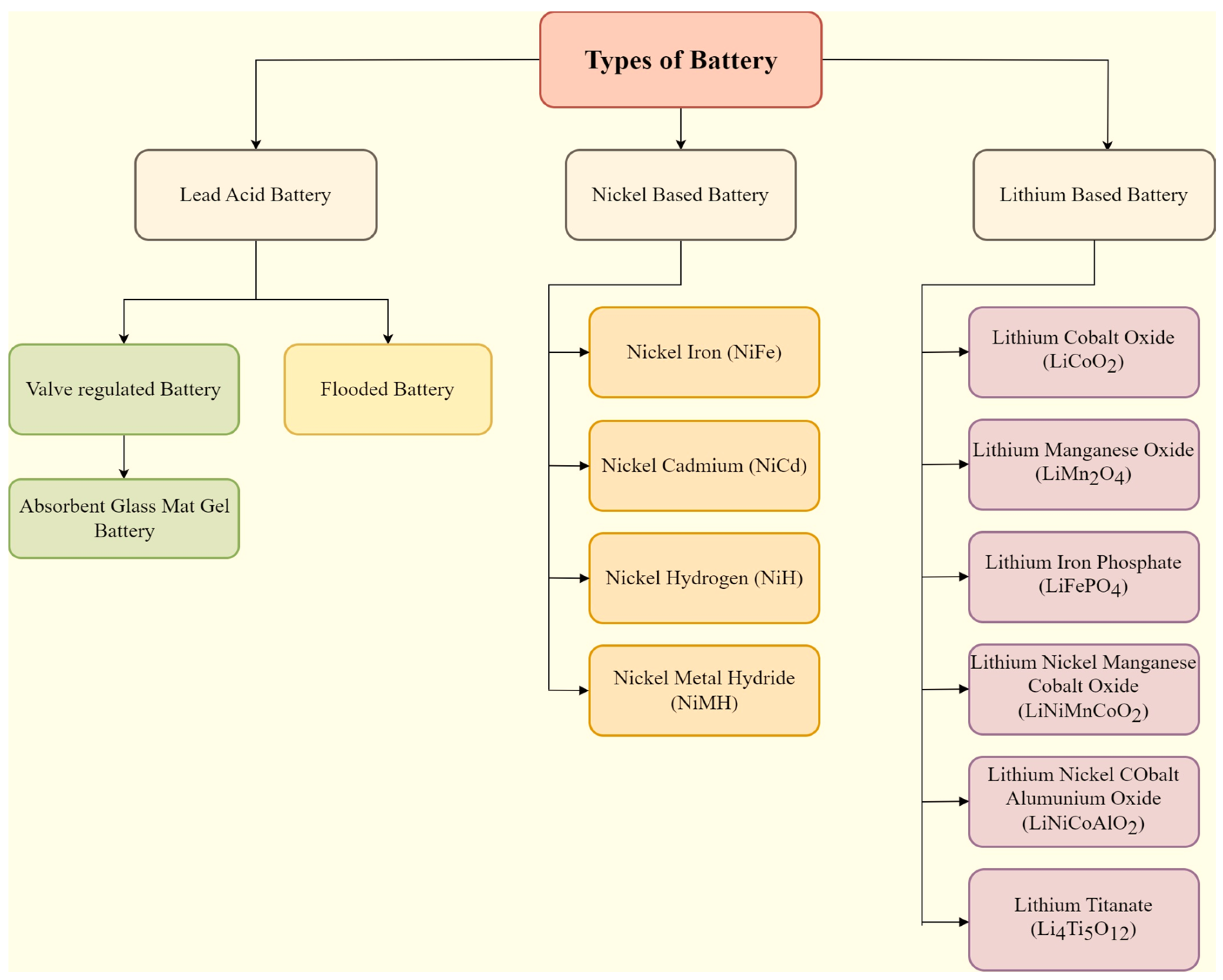
2. Different Battery Chemistry

EVs equipped with batteries are now exerting a significant influence on the automotive industry. The construction of contemporary EVs involves the use of several battery technologies, posing a challenge in identifying the most suitable option that effectively fulfils the essential criteria across multiple dimensions. These dimensions include energy storage efficiency, structural attributes, safety considerations, operational lifespan, and cost considerations. The detailed classifications of different types of battery that are used in EV are displayed in Figure 1.

2.1. Lead-Acid Battery

This was the earliest rechargeable battery, introduced in 1859. There are many good reasons for the popularity of the battery. One of them is their cheapness on a low cost-per-watt basis. Mostly, the frame of the battery is built from lead alloy as pure lead cannot support itself. So, to add mechanical strength, many common metals are used, such as antimony, tin, calcium, selenium, etc. [30]. Lead acid batteries are mainly classified into two categories, flooded and valve-regulated. Both of the battery types are almost similar but the main difference between them is their system design, such as a flooded battery requiring alignment to prevent the leakage of electrolyte while value-regulated batteries do not. A flooded battery also requires a ventilation system to send out the gases formed during the cycling, while valve-regulated ones do not. Valve-regulated lead batteries are further classified into two types: gel and absorbed glass mat (AGM). The main difference between the two batteries is in the form of electrolyte stored in the battery. In the gel type, a condensing agent is used to change the material from liquid to gel, while in AGM a glass matrix is used. Figure 2 shows the comparison between Gel and AGM batteries’ performances in relation to their available power, cost, capacity, life cycle, thermal runaway, and deep discharging.

Applications of Lead Acid Battery

This is widely used in the automobile sector such as in EVs, forklifts and golf carts. It is mainly used to power the cranking motor and other electric systems present in vehicles. An acid battery is also used in backup power systems in businesses, homes and critical facilities. It is also used in marine applications such as for powering boats and other marine applications.

2.2. Nickel Battery

2.2.1. Nickel–Iron (NiFe) Battery

This was first developed in 1901 by Edison and Jungner. The positive terminal of the battery is made up of nickel oxyhydroxide, whereas the negative terminal is of iron material [31]. The battery has a low specific energy and exhibits a huge self-discharge rate. The main key problem in the growth of the battery is iron poisoning of the negative electrode. Due to its resistance to vibration and high temperature, the battery is used in mining in Europe.

2.2.2. Nickel–Cadmium (NiCd) Battery

The developmental work performed regarding this battery was mainly contributed by Edison and Jungner. Also, a tubular plate-type battery was invented by Edison in the year 1908. The main reason behind the introduction of this battery was to restrict the mechanical distortion formed because of the bulging of the positive electrode in a pocket plate battery [31]. It was also helpful to increase the battery life cycle in the deep-discharging-cycle process. But due to the high manufacturing cost, the battery was not further manufactured. The performance of a nickel—cadmium battery depends on many factors, which includes cell construction, the production process, the cell type, the operating temperature, etc. It has many advantages such as a high cycle count, ultra-fast charging with little stress, a prolonged shelf life and many more. But it has many disadvantages, such as diminished specific energy, cost, a huge self-discharge rate and many more [32].
Figure 2. Comparison between gel and AGM battery [32].
Wevj 14 00325 g002

2.2.3. Nickel–Hydrogen (NiH) Battery

The construction of this battery is almost identical to the cadmium battery. The difference is created by replacing the electrode. In this battery, the cadmium electrode of the battery is replaced by a standard hydrogen electrode, which enlarges the energy density value of the battery [32]. The battery was specially designed for aerospace applications. The main advantages of the battery are a long life, a good life due to low corrosion, low self-discharge, etc.

2.2.4. Nickel–Metal Hydride (NiMH) Battery

Ni-MH batteries are a crucial type of battery used in portable electronic devices. They were first patented in 1986 and became widely marketed in 1989. Its design resembles that of a Ni-Cd battery quite a bit [30]. Metal hydride batteries took up a huge amount of attention because of their huge valued energy density, huge discharge rate and high tolerance to over discharge. These batteries also have resistance from dendrite formation and memory effects because of recrystallization.

2.2.5. Applications of Nickel-Based Battery

Nickel–cadmium batteries are used as the main battery in aircrafts, whereas the metal hydride battery is used in hybrid cars and in uninterruptible power supply (UPS). The nickel–iron battery is used in rail road signalling, mining and in rockets. Nickel–hydrogen batteries are exclusively used in satellites and in space programs.

2.3. Lithium-Ion Battery

After the remarkable work conducted on lithium-ion batteries in 1991, they have become popular among the battery market because of their high energy density and prolonged life. The anode and cathode of the battery are split with the help of a separator and electrolyte. But the most important characteristics of the battery includes a long life, discharging and charging efficiency, a low cost, a large temperature-range performance, etc. Mostly, lithium batteries are packed in two popular formats. The first is in metal cans (prismatic or cylindrical shapes), which are also known as Li polymer batteries. Another form is a stack formation, in which gel is used to prevent the leakage of the electrolyte [32]. Generally, the main power source of the battery is active lithium-ion movement from the cathode to the anode. So, to achieve a huge value of capacity, a high amount of lithium is used. Hence, different types of cathodes are used, which include lithium manganese oxide, lithium cobalt oxide, lithium iron phosphate, etc. [33].

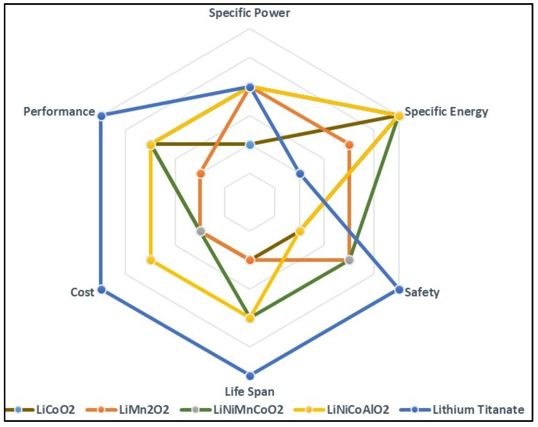
2.3.1. Lithium Cobalt Oxide (LiCoO2) Battery

In 1991, Sony created this battery and Mizushima improved the battery materials as per the patents [34,35]. It contains cobalt oxide as the cathode and graphite as the anode. The battery itself has a diminished life time, small load capacities and needs shielding against overheating and immoderate stress, but has a quick charge time [36,37].

2.3.2. Lithium–Manganese Oxide (LiMn2O2) Battery

Li et al. first introduced this battery in 1983 in a material research bulletin [38]. Its 3D spinel shape helps the battery to lower its internal resistance for quick charging and gives a high discharging current. Due to its 3D architecture, the battery has positive aspects, such as a high point thermal stability and safety. But this limits the life of the battery. It provides approximately 50% more specific energy than a battery based on nickel. The battery has a higher capacity loss during the recharging cycle as a large amount of manganese decomposes in the electrolyte at a high temperature [39].

2.3.3. Lithium–Nickel–Manganese–Cobalt Oxide (LiNiMnCoO2) Battery

This battery mainly comprises of nickel, manganese and cobalt, all in proportions of one-third each. The main secret of the NMC battery lies in the addition of nickel and manganese in it. Nickel has prominent specific energy but has low stability, whereas manganese has the property of a spinel architecture, allowing it to achieve small internal resistance, but comes with small specific energy [40]. Adding the metals in the battery together enhances the strength of each one. This battery is in huge demand because of its low self-heating change.

2.3.4. Lithium–Nickel–Cobalt–Aluminium Oxide (LiNiCoAlO2) Battery

This battery consists of mixed metal oxides. Metal oxides have particular importance in their applications when manufacturing the battery. This battery has a much-diminished share in the world market [41]. But now, experts are interested in the battery because of its impressive profiles (power density, specific power, cost, and safety) [42].

2.3.5. Lithium-Titanate-Oxide Battery

The titanate anode in LIB has been commonly used since 1980 [43]. It is a replacement for the graphite anode and has a spinel structure. But due to its low specific energy, the battery is still in the development zone and work is still pending on it.

2.3.6. Applications of Lithium-Ion Battery

From the above information, we can easily say that the LIB has a good energy density value. Therefore, LIBs are mostly used in next-generation biomedical applications, in electric automobile applications and in aerospace. The battery cells are arranged in a different connection to render a high energy, and these arrangements are used in powering heavy electric vehicles and EVs and also in other applications.
Comparisons of different types of LIBs used in EVs from the following perspectives: specific energy (SE), specific power (SP), safety (SF), performance (PF), life span (LS), and cost (CS) is shown in Figure 3.

3. Battery Management System
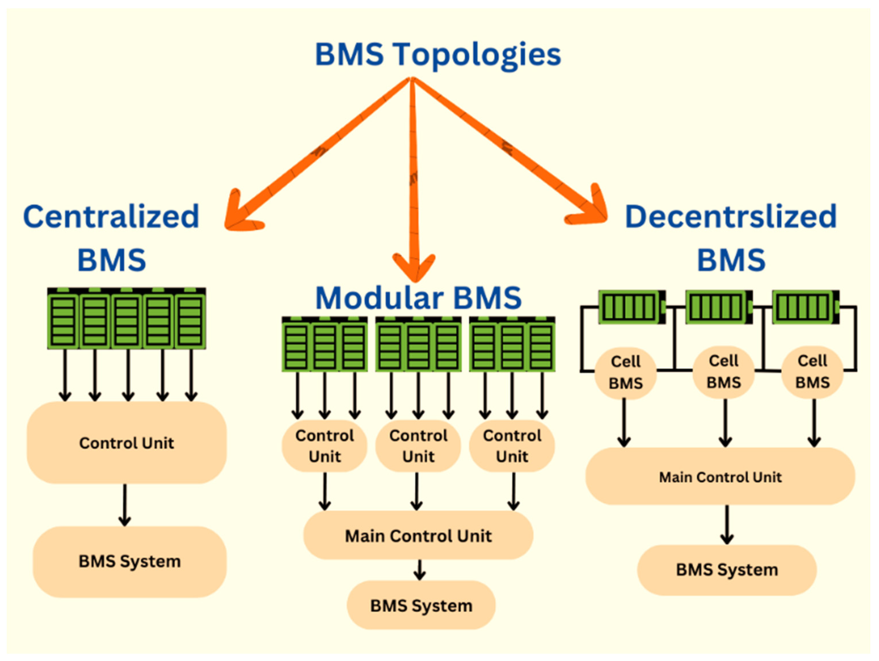
3.1. Types of BMSs

In Figure 4, different BMS topologies are shown with their schematic views and connections.

3.1.1. Modular BMS

A modular BMS is designed with a modular construction, or it can also be stated that the system is divided into different modules based on the functions or application of the unit. The various functions or tasks of the system, such as current and voltage measurement and monitoring, temperature sensing, cell balancing and other functions, are sorted into different or isolated modules, with each having its own hardware and software part or components. The main architecture of the modular system is based on the communication or connection between the main controller and the distributed modules. All modules are commonly linked with a communication bus, like a Common Area Network (CAN), Ethernet and others like RS-485. Each module of the system has its own microcontroller and sensors with other required components. The main controller is responsible for all the decision and data co-ordination. It can also be linked with the other services to provide real-time data present in the system. In [44], the design, deployment and implementation of a modular BMS is discussed for IoT applications. The main advantage of the BMS is improved manageability. The different modules of the BMS can be located nearer to the batteries, which avoids long cable connections. The scalability of the system can also enlarge in comparison to centralized BMS. The cost of its modularized units is higher than centralized BMS. A modular BMS can be further classified on the basis of its specific requirement of application such as at the string level, module level and cell level.
  • String level: in this system, each BMS module is accountable for controlling and monitoring a group of battery modules or cells, which are in a series connection;
  • Module level: in this system, each BMS module is accountable for controlling and monitoring a single battery module or sub pack in the battery;
  • Cell level: in this system, each BMS module is accountable for controlling and monitoring a single battery cell.

3.1.2. Centralized BMS

The centralized BMS is designed with a centralized architecture, or we can state that there is only one integrated unit or controller in the whole system. Here, complete functionality is merged into a single unit or module, which is attached to the battery cells or battery unit via several connection wires [45]. The essential or main components of the system include the controller, communication interfaces and sensors. The primary or central controller is accountable for various functions such as cell voltage and current monitoring, temperature status and others. Mainly, the centralized system is used in stationary energy storage systems such as renewable energy storage (RES), and in some EV applications as well. The main benefits of the system include cost-efficiency, repair and management. If only one integrated circuit is utilized, the cost of the application reduces and errors can also be easily identified. The plain defined structure of the system provides effective control of the system. But the huge cable connection increases the probability of short circuits in the system. Moreover, the inputs in the system can easily be incorrectly connected and mixed up. The main controller in the circuit is only point of defeat. In the case of the malfunction or failure of the main controller, the whole system is endangered or can become uninterruptible.

3.1.3. Decentralized BMS

The decentralized BMS is designed with a distributed architecture [46]. In this architecture, the various functions and tasks of the system are bifurcated into multiple units or controllers that are allocated all over the battery pack. In this system, each module of the BMS is accountable for controlling and monitoring a specific subset of the battery, such as the modules, string or groups of cells. Becoming popular in the EV industries, it has several advantages like scalability factor, growing functional safety and minimum integration efforts. All the units of this system are connected with other using a communication bus network such as CAN, Ethernet or RS-485. In this system, the main BMS controller is responsible for managing the tasks of various units. A decentralized BMS without a communication system is proposed in [37]. The main advantage of the system is the number of inputs; it is not fixed for the system. It can be extended or reduced even after attachment of the system. Moreover, its flexibility and scalability are also some advantageous factors. Overall, a decentralized BMS offers a flexible, cost-efficient and fault-tolerant solution for managing the performance and safety of a battery pack.

3.2. Battery Thermal Management

The temperature management system of its battery is one of the most important parts of an EV. Therefore, a key area of study focus is in the thermal management of the battery’s ideal operating temperature range during discharging and charging modes. At the time when an electric vehicle gets charged, discharged, and operated, the system is utilized to estimate the temperature of the battery pack. With a higher temperature-related fault operation, component failure rates rise. The battery-pack temperature is monitored by thermal management systems to avoid this. In order to initiate the cooling procedure and control the temperature as the temperature increases, a signal for control is supplied to the coolant circuit [47]. Battery longevity and safety throughout charging and discharge cycles in vehicles depend on maintaining the battery’s temperature in an appropriate temperature range between 25 °C and 40 °C [48], as thermal runaway can result in fires in battery packs. A variety of thermal management schemes are frequently applied in a battery to guarantee stability of its temperature and provide cell temperature uniformity [49]. Liquid- and air-cooling structures are categorized as active cooling components [50] because they consist of pumps, fans and other equipment. Active cooling systems need a larger area and electricity to operate than PCMs, which are referred to as passive systems for thermal management [51]. The air-cooling technique is the easiest and most energy-efficient type of construction, but due to its low efficiency, it is often not suggested for large power applications. On the one hand, liquid cooling provides the best consistency and efficiency but comes at the cost of a higher complexity, volume, and energy use. More advanced methods are effective, simple to incorporate, and compact, such as PCM, which is a thermoelectric component, or hybrid cooling. However, their installation comes at a higher cost, and in some situations, it makes the battery-pack system as a whole much more challenging to maintain due to the BMS’s integration of all battery sensory circuits. The system’s output, which might be digital or analogue, will change how much power is needed by the thermal control system to warm, equalize, and cool a battery cell.

3.3. Cell Balancing

Voltage, the capacity fade rate, the SOC and the aging rate among cells may be inconsistent due to variations in reactions and manufacturing processes. Therefore, cell voltage equalization is extremely significant. Technologies for cell balance can be divided into two categories: balanced cells can be either passive or active.

3.3.1. Techniques for Passive Cell Balancing

The former approach diminishes the total battery lifespan by facilitating the dissipation of excess power from the battery cells using resistors, unless the charge level aligns with that of the pack’s less-charged cells or an equivalent charge level. The use of the passive cell balancing technique is relatively uncomplicated; nevertheless, its efficiency is comparatively lower. Therefore, it is not recommended to utilize this approach during the discharge process. One of the most straightforward approaches to achieve cell balancing is through the use of shunt resistors. These resistors may be divided into two types: fixed resistors and variable resistors. In the context of the fixed shunt resistor, the manipulation of resistance serves as a means to restrict voltage, while concurrently allowing for the continuous bypassing of current. Rather than engaging in the continuous discharge of cells with high charge, a variable resistor approach employs controlled relays [52,53].

3.3.2. Techniques for Active Cell Balancing

The active cell balancing technique involves the transfer of charge across cells with varying levels of charge, using either capacitive or inductive flow. The correction of cell imbalances may be achieved by securely transferring electrical energy from a lower SOC to a greater SOC. In comparison to passive balancing techniques, this approach demonstrates more efficacy in optimizing the available power of the battery, since it facilitates the transfer of surplus energy to a low-energy cell rather than allowing it to dissipate [54,55].

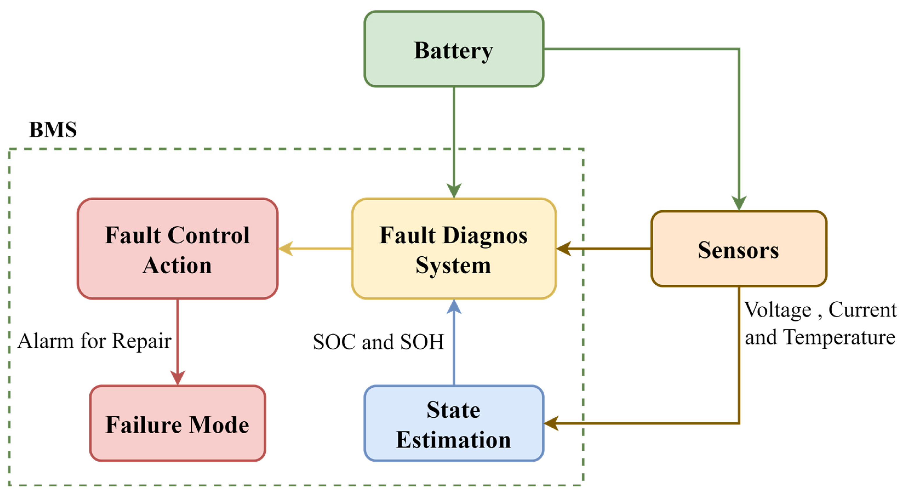
3.4. Fault Diagnosis

In EVs, defect diagnostics is a critical supplementary function of BMS. There are many different fault types, including actuator faults, cooling system faults, internal/external short-circuits, thermal runaway, overheating, overcharge or overdischarge, external or internal short-circuits, sensor faults, internal/external faults, overheating and cell connection failures. A lot of emphasis has been placed on distributed fault diagnosis first. One of the primary duties of the BMS is to mitigate the potential hazards inherent in using a battery pack, hence safeguarding the well-being of both the end-users and the battery itself. The majority of dangerous circumstances are brought on by defects, which should be prevented by the safety features of the BMS by reducing their frequency and severity. With a view to assure the security of the battery system, sensors, contactors, and insulators are frequently included [5]. Additionally, there are limits of operation for temperature, current and voltage, which are tracked by sensors linked to the battery’s cell [56]. As a result, fault diagnostic techniques are necessary for BMS. These algorithms provide the functions of prior failure detection and give the batteries and users suitable and prompt control actions [57]. BMS continuously monitors the battery system, utilizing sensors, state estimates, modelling, and data analysis in order to spot any anomalies that may arise when the battery system is in use [5]. Effective completion of this task is challenging due to the numerous internal and external flaws. For the proper identification and isolation of a particular defect and the application of the appropriate control action, several fault diagnostic techniques must cooperate. The BMS’s fault diagnostic methods, however, are constrained in terms of computer power and time. These fault diagnostic methods must have a low processing effort, yet maintain accuracy and reliability, due to the huge quantity of battery pack’s cells in many applications [58]. The schematic diagram of fault diagnostics in the BMS is depicted in Figure 5.

3.5. FMEDA BMS

FMEDA is the Failure Modes, Effects and Diagnostics Analysis of BMS. It is a crucial requirement for obtaining certification according to IEC 61508, through conducting a risk assessment. It serves as a key tool in the process of detecting and evaluating all related risks and hazards. FMEDA is a comprehensive assessment that scrutinizes various failure modes and the diagnostic functionalities of equipment. The provided table displays a preliminary FMEDA for each of the pertinent major components. Table 1 presents the diverse FMEDA conducted on the BMS designed for large-scale integration [59].

3.6. Performance and Safety Test Standards for BMS

This section highlights some safety considerations, including overvoltage protection and cell balancing, which are vital components to be included in any documentation pertaining to BMS. Moreover, Table 2 provides a comprehensive overview of the primary performance and safety assessments pertaining to stationary applications, as outlined in the various standards or recommendations.

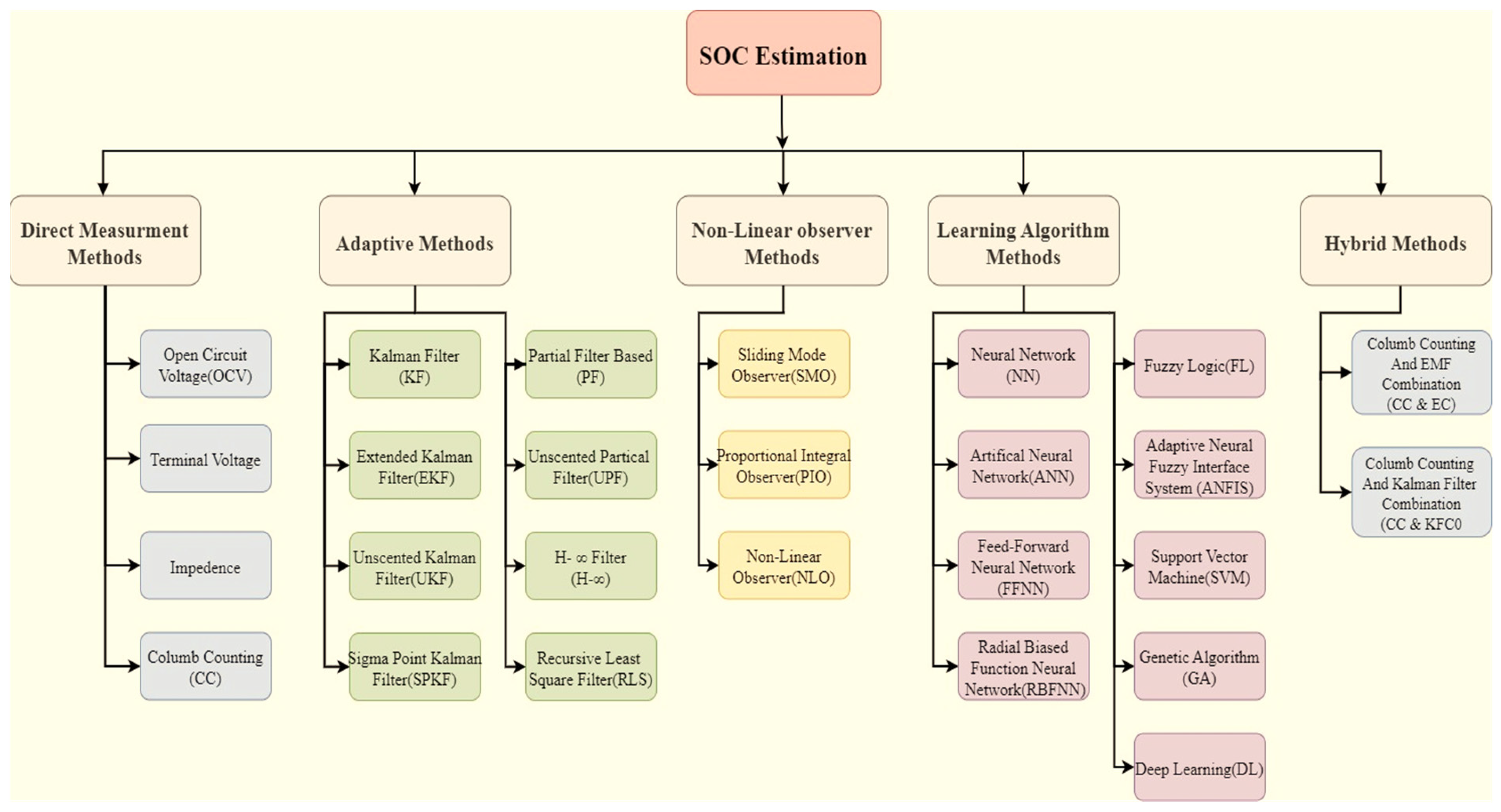
4. Methods of SOC Estimation

One of the most important aspects of batteries is the SOC, although describing it presents a number of difficulties [15]. The term SOC is often used to denote the ratio between a battery’s current capacity Q(t) and its nominal capacity Q(n). The nominal capacity refers to the upper limit of charge that a battery can store. The SOC may be computed using the following Equation (1).
S O C t = Q t / Q n
These SOC-estimating approaches are classified in five different ways, which are adaptive methods, direct measurement methods, the non-linear observer method, learning algorithm methods and the hybrid method. Figure 6 shows the detailed classification of SOC estimation methods.

4.1. Direct Measurement

This method employs battery parameters such as voltage and impedance. Many more approaches have been used, including the OCV, terminal voltage, and impedance measurement techniques.

4.1.1. OCV Methods

The OCV method produces a battery SOC estimation value that can be used to calculate the battery capacity. As there is no voltage drop to the load or the voltage is not shared with the load, OCV represents the whole source voltage. OCV is a voltage state that occurs when the voltage source is not connected to the circuit or the load. The battery’s SOC and its OCV have a roughly linear connection, as shown by Equation (2):
V OC t = a 1 × soc t + a 0
where a0 is the terminal voltage of the battery when the SOC = 0%, and a1 is found from a0 and VOC(t) at SOC = 100%. It should be noted that all batteries will not have the same SOC-OCV connection. A pulse load is applied to the LIB and allowed to approach equilibrium, allowing researchers to assess the OCV connection with SOC [65].

4.1.2. Terminal Voltage Method

Since the terminal voltage approach is based on the terminal voltage decreasing due to internal impedances when the battery is depleting, the EMF of the battery is proportional to the terminal voltage. The terminal voltage technique has been applied at various temperatures and currents [66].
Though the battery’s terminal voltage sharply drops towards the discharge, the projected inaccuracy of this method is important [67].

4.1.3. Impedance Method

By recording the voltage and current during sinusoidal excitations at various stimulation frequencies and computing the complex quotient of these signals to determine the cell impedance, an impedance measuring system is created. In the Nyquist plane, two circles can be used to represent the impedance of a battery cell [68]. The chemistry of a cell has a major impact on the impedance spectrum’s curve: electrochemical impedance spectroscopy (EIS)-based techniques have recently been used to accurately analyse electrochemical processes that occur in real time and diagnose lithium batteries [69,70].

4.1.4. CC Method

For calculating SOC, the discharging current is the input used in the book-keeping approximation technique, which integrates the discharging current over time. This approach enables the inclusion of nearly internal battery effects, such as the capacity loss, self-discharge, and effectiveness of discharging. The CCM is one type of estimating technique used in book-keeping. The SOC is most frequently calculated using the CCM in industry [71]. This technique uses battery current measurements that have been mathematically integrated during the usage time to determine SOC values provided by Equation (3):
SOC = SOC t 1 + I t / Q n × Δ t
where I(t) is the discharging current, and SOC(t − 1) is the previously estimated SOC values. Though the CCM is a direct approach, it has disadvantages such a primary value error and compounded errors; thus, the following considerations must be made: batteries’ currents can be measured, but there is always a chance for measurement noise and inaccuracies. Equation (3) eventually loses accuracy owing to compounded mistakes caused by noise, a broad range in sensor resolution, and rounding errors. As a result, supporting algorithms are required. In the context of thermodynamic equilibrium in battery systems, it is possible that determining the initial SOC may provide practical challenges, hence limiting the ability to precisely characterize the SOC of a battery [72]. This technique is unable to totally decrease the accumulative error. The CC method was used as the only tool to compute the SOC in [73]. Since it includes a method that enables an on-line adaptive parameter estimate of a source-dependent electric circuit model (ECM), this study employs CCM as a special approach for the SOC estimation.

4.2. Adaptive Method

The adaptive methods are self-designing and may automatically normalize the SOC for different discharge situations.

4.2.1. KF Methods

KF is a clever and well-designed instrument that is frequently used in aircraft, navigation tracking, and automotive applications. The self-correcting nature of the KF is its most notable characteristic. A KF linear model has two equations: a state equation that forecasts the state at a certain time and a measurement equation that changes the state at that time [74], which are calculated using Equations (4) and (5):
State   Equation : S m + 1 = E m s m + F m c m + p m
Measurement   Equation : T m = G m s m + H m c m + n m
where E, F, G, and H denote the covariance matrices, S is the state of the system, p is the noise of the process, c is the input of the control, m is the input of the measurement, and n is the noise of the measurement. A RC battery model for simulating a KF was created by Ting et al. [75]. The RC model’s mathematical equations are still used, but they have been transformed into a state–space model to represent the battery properties. The conclusion showed that, in comparison to the observed error, the predictable value of the root-mean-square error (RMSE) for the SOC using the KF is small. Using the dSPACE and MATLAB software, the researchers of [76] also applied a similar methodology to the ECM of an LIB. Less than 5% SOC inaccuracy was calculated. In order to improve the non-ideal factors, Yatsui [77] integrated the KF findings with the CC and OCV approaches. The SOC precision was increased when the KF was run, with an inaccuracy of just 1.76%. The KF, however, cannot be utilized immediately. It requires intricate calculations and is extremely resilient to a variety of operating environments and battery ageing. However, MI-UKF is immune to unexpected operational demands and can increase the accuracy of UKF by more than 1% [78,79,80]. Also, the state of trajectory prediction based on KF for object tracking was carried out in [81].

4.2.2. EKF Methods

Due to the inherent inability of the KF to effectively account for the nonlinear characteristics shown by battery models, the EKF has often been used as a suitable alternative in nonlinear applications. The process of linearizing the battery model in the EKF involves using a Taylor series. In order to refine the estimated parameters for SOC, the predicted value is compared to the observed voltage of the batteries. This comparison necessitates the linearization of the state–space model at each occurrence in time. While the accuracy of first-order Taylor series is compromised in highly non-linear scenarios [82], there is a possibility of encountering a linearization error when dealing with systems that exhibit significant non-linearity. To estimate the SOC and the capacity of a battery using the recommended OCV–SOC relationship, Lee et al. [83] developed an electrochemical model using a dual EKF. The construction of the standard OCV–SOC data relies on a reference voltage, with a selected cut-off value of 3.6 V, which is arbitrarily designated for the purpose of establishing the correlation between OCV–SOC. The predicted conclusion indicated that the model exhibited more accuracy compared to the actual number, with a lowered primary error rate of 5%. In reference [84], the SOC estimation for LIBs was conducted using a nonlinear battery model and an EKF. The nonlinear model was formed by sequentially coupling a second-order RC model with an OCV model, both of which exhibit nonlinear behaviour. The EKF is used in order to mitigate the adverse effects caused by measurement and process noise. The proposed technique demonstrates enhanced accuracy in forecasting the SOC, particularly in cases when the original SOC is not known. In reference [85], the authors used the EKF and its dual variant, the Dual EKF, to estimate the SOC of LiFePO4 cells. These estimation methods were applied for the zero-state hysteresis (ZSH) model and the hysteresis state model. The outcomes indicated that the suggested methodology is capable of accurately estimating the SOC in dynamic scenarios, with a margin of error of 4%.

4.2.3. UKF Methods

The UKF technique is used to solve these issues because EKF only works in the first and second orders of a nonlinear model and introduces a sizable inaccuracy in extremely nonlinear state–space models. With the help of the unscented transform and the discrete-time-filtering method, UKF is an upgraded type of KF that addresses filtering issues. The UKF approach demonstrates the capability to effectively and precisely estimate the covariance and mean values associated with the Taylor series. However, the technique has weak resilience as a result of modelling uncertainty and system perturbations. For UKF-based SOC estimate, He et al. [86] took battery voltage and CC into consideration. The UKF is utilized to autonomously control the model parameters, with the objective of reducing the inaccuracies in the SOC estimation caused by variations in external conditions and battery self-discharge. Data gathered from LiFePO4 batteries used in various experiments were used to gauge the method’s performance. In order to estimate the SOC in LIBs online, the Adaptive UKF (AUKF) was presented by the authors in [87]. One benefit of this method is that it allows for adaptive correction of the noise covariance in both the process and measurement state. Additionally, due to the ZSH model’s straightforward design, this strategy may be put into practice quickly and with minimal resources. The comparison analysis conducted on the algorithms EKF, AEKF, and UKF demonstrates that the AUKF model exhibits superior performance and accuracy.

4.2.4. SKF Methods

Another alternate approach for evaluating states in a non-linear system is SPKF. With a small number of functions, SPKF outperforms EKF in terms of its mean and covariance accuracy. The method selects the number of sigma points that perfectly match the mean and covariance values of the model that is being built. This model has the same computational difficulty as EKF without taking Jacobian matrices into account, which is a benefit. Additionally, the original function and derivatives do not need to be computed by the model. In [88], three model-based algorithms, SPKF, EKF, and the Luenberger observer, were evaluated for their ability to estimate the SOC for LiFePO4 batteries. According to the experimental findings, SPKF increases the SOC estimation’s accuracy while taking battery tracking precision and resilience into account. Since SPKF does not need the computation of Jacobian matrices, it also provides stability in numerical computations.

4.2.5. PF Methods

The estimation of states is conducted with the PF algorithm, which employs the Monte Carlo simulation technique by employing a non-Gaussian distribution and arbitrary particles to approximate the PDF of a non-linear system. Two methods for the estimation of SOC using PF were developed by Gao et al. [89]. The relationship between the SOC value and the variable discharge current is described by the process model, whereas the relationship between the SOC, the discharge current and the temperature on the battery terminal voltage is depicted by the measurement model. The simulation results show the suggested approach to be effective, since it has a calculation time that is six times quicker than EKF. In their study, He et al. [90] introduced the UPF method as a means of measuring the SOC in high-power LIBs. When developing a new model, several factors are considered, including the temperature, charge/discharge rate, drift noise, and operating miles. UPF has a superior performance to UKF in numerical calculations, as shown by a reduction of 30.2% in the RMSE and 12.6% in the Maximum Absolute Error (MAE).

4.2.6. H-∞ Methods

The H-∞ filter takes into account the dynamic parameter of the battery and does required the awareness of any details regarding the characteristics of measurement and process noise. It is a straightforwardly constructed model with significant resilience to functioning in certain circumstances. However, the accuracy of the model might be affected by ageing, hysteresis, and temperature impacts. For the purpose of estimating a lithium-ion battery SOC, an H-∞-based approach is introduced in [91]. The analysis of a second-order RC filter circuit included the consideration of time-dependent properties. In order to obtain parameters of the model like voltage, current, and resistance, a Hybrid Pulse Power Characterization (HPPC) experiment was run. The suggested model was tested using six Urban Dynamometer Driving Schedule (UDDS) cycles and improved the accuracy of the battery, with a respectable SOC estimate error of 2.49%. The SOC of a LIB was estimated using a universal linear model in [92] that used an adaptive H-∞ filter (AHF). Since the process of charging and discharging in each cycle is connected to both free parameters and the SOC, some of the model’s parameters were taken into account as a function of SOC.

4.2.7. RLS Methods

RLS is a valuable technique that finds use in time-varying systems. The adaptive dynamic model parameters are calibrated by the algorithm using the forgetting factors. In reference [93], a proposed approach is presented for estimating the SOC using a recurrent neural network (RNN) that is based on an adaptive model. With the aid of the forgetting factor, the RLS method is utilized to predict the model parameters for calculating SOC. The predicted value of SOC is afterwards matched to the actual value, revealing that the model exhibits strong performance, with a peak error of 1.032%.

4.3. Non-Linear Observer Method

4.3.1. SMO Methods

To ensure the strength and resilience of the system over disturbances and the uncertainty of the model, SMO has been used to improve tracking control. The state equation is used to create the output state for the model, which is then broken down into the viewer’s equations in the subsequent step. To ensure the resilience features, the sliding regime is controlled by feedback switching gain. Kim et al. [94] established a technique for SOC estimation of a battery by using a simple RC circuit and an SMO. The suggested methodology effectively controlled the convergence time when subjected to a high charge/discharge value. The resilience of the model was significantly enhanced, resulting in its successful performance even in the face of uncertainties and disruptions. The processes underwent validation utilizing the UDDS, and the results revealed that the SOC inaccuracy was below 3%. Chen et al. [95] used the Adaptive Gain SMO (AGSMO) method on a composite ECM to approximate the SOC. The extraction of model parameters was performed based on the battery pulse charge, while the circuit model and terminal voltage were used to generate the state equations. The SOC is calculated using a battery ECM in [96] based on AGSMO. Both urban and suburban locations were used for validation tests, and the findings showed promise in terms of the SOC error, which was less than other traditional methods based on SMO. An improved SMO was suggested in [97] for estimating the SOC of liquid-metal batteries. First, the forgetting factor RLS approach was used to determine model parameters across the entire working range based on a combined ECM. To effectively examine the linear correlation between the SOC and the OCV, a direct differentiation method was proposed. In [98], to obtain a precise estimation of SOC, the study used a Terminal SMO (TSMO) technique that was founded on a hysteresis RC ECM. In [99], a new estimation approach for LIB SOC is presented. A fractional-order SMO was presented to estimate the SOC and voltage based on the equivalent Thevenin model, and the stability evidence was provided. This method exhibited a superior accuracy and robustness to the widely used KF method.

4.3.2. PIO Methods

PIO is an effective control technique that has been used extensively to replace feedback control systems. This controller’s job is to rapidly and accurately converge the predicted voltage to the actual voltage. An LIB RC battery model was created by Xu et al. [100] for the purpose of estimating the SOC using PIO. The battery model’s observability matrix was then created in order to reconstruct the state variables. Using a test workbench, the battery model was determined from the SOC–OCV relationship. Additionally, the suggested model was authorized using the UDDS driving cycle, and the outcome of study indicates that the error is restricted to 2% when in comparison with known and unknown SOC situations. In [101], a multi-level PIO-based rapid estimation technique for battery impedance and SOC was discussed. The system compensation factor was then added to the observer to dynamically alter the battery model’s parameters as the observer model reflected changes in the battery state characteristics through dynamic impedance. The experiment, known as the compound DST, served to validate the algorithm’s efficiency. An enhanced adaptive PIO is suggested in [102] to further improve the accuracy of the estimation of charge state. Battery settings were updated in real time based on the charge level and error feedback. In this work, the battery model was discussed, together with the development of an enhanced adaptive PIO. To test the approach, a first-order RC model was created in MATLAB.

4.3.3. NLO Method

Numerous observers, both non-linear and linear, have been utilized to determine the state [103,104,105]. Although the linear observer is frequently utilized, its employment increases the SOC estimation’s error. Xia et al. [106] suggested an NLO-based SOC estimate approach for LIBs. The ninth-order polynomial and state–space equations were used to estimate the SOC from OCV. The model was verified via the use of an urban driving cycle test and discharge test. The outcomes indicate that the proposed approach outperforms both the EKF and SMO in terms of its accuracy, convergence speed, and computing cost. The development of a nonlinear observer with terminal voltage feedback injection (VFNO) is described in reference [107] for the purpose of monitoring the SOC of LIBs. This observer is based on the electrochemical single-particle (SP) model. The use of the Lyapunov stability theory was employed to establish the convergence of the SP-VFNO system, accounting for the presence of measurement error. The battery testing system measures the current, SOC reference and the terminal voltage value. The results of the experiments show that the suggested SP-VFNO approach is superior, with a quicker rate of convergence and an improved prediction precision, which can aid in the correct estimation of the SOC for BMS in real-world applications.

4.4. Learning Methods

4.4.1. NN Method

An intelligent mathematical tool known as an NN can demonstrate a complex nonlinear model due to its adaptability and capacity. In order to construct the NN network of LiFePO4 batteries, the NN requires inputs of the discharge current, terminal voltage, and temperature, and the outputs of the SOC. This method has the benefit of being able to operate in non-linear battery scenarios when the battery is being charged or discharged. Still, the method maintains a lot of data for training, which overloads the system and necessitates a lot of memory storage. In order to allow for the impact of hysteresis OCV, Chen et al. [108] proposed an EKF-based battery model. After that, NN and EKF were combined for the SOC estimation. The projected conjunction model performs best in regard to estimation accuracy, with an error of less than 1%. For identifying a suitable NN model, the inputs used include the voltage at the present state, the SOC, and the current. Additionally, the output of interest is the voltage, as shown in reference [109]. The trained model is converted to a collection of state–space equations, after which the SOC is calculated using the EKF method. The capacity estimation of LIB is proved via the use of charge–discharge tests and back-propagation neural networks (BPNNs) [110]. The model employs capacity as the dependent variable, while the discharge current and voltage are included as independent variables. Additionally, the RBFNN is a practical mathematical approach for calculating the SOC if the system has partial data. In terms of efficiency and precision, this method is extremely good for designing a battery model.

4.4.2. BPNN Method

The most common variety of ANNs is the BPNN. BPNNs are often used in the estimate of a SOC because of their remarkable properties [111]. SOC estimation is characterized by a nonlinear and extremely complex association between the target and input [112]. A battery’s recent history of voltage, current, and ambient temperature are used by the ANN-based SOC indicator to estimate the current SOC [113].

4.4.3. ANN Method

An ANN, a nonlinear map displaying a complex nonlinear model can be created using the NN approach [114], which has exceptional potential. The calculation of SOC in this study was based on an OCV approach, utilizing a dual NN fusion LIB model. Specifically, the linear neural network LIB simulation was employed to determine the parameters of ECM. Additionally, a second BPNN was utilized to establish the relationship between OCV and the SOC [115]. An additional advancement in BPNN led to the creation of a method that enhances prediction accuracy and robustness by combining Particle Swarm Optimization (PSO) and principal component analysis [116]. The overfitting of the model was suppressed by employing a load-classifying NN model for predicting SOC [117]. A NLO constructed using an RBFNN and employing a complete ECM has also been presented [117]. In the field of SOC estimation, a nonlinear autoregressive with exogenous input-based NN was proposed by Lipu et al. [118]. In recent times, a recurrent nonlinear autoregressive NN with external inputs was introduced by Hannan et al. [119], and it used a search procedure to improve SOC estimation. PSO was used to determine an SOC using the Levenberg–Marquardt optimized multi-hidden layer nonlinear neural network model, suggested by Xia et al. [120]. To describe LIB dynamics and estimate the SOC, a stacked LSTM recurrent neural networks was developed [121]. Despite the original SOC being wrong, the method quickly estimates the true SOC. Recently, a similar strategy that used transfer learning to quicken NN training, and a rolling learning technique to incorporate SOH influence, was presented [122]. This method produced precise predictions under many circumstances, making it simple to apply a well-trained model to batteries with related chemistries. Chen et al. [123] made more strides by utilizing a moving horizon estimate and an autoregressive LSTM for SOC estimation. The authors made additional progress by utilizing a moving horizon estimate and an autoregressive LSTM network for SOC estimation. This method’s suitability for SOC estimation in cases of ambiguity or significant departures from the initial SOC, even when the original SOC turned out to be inaccurate, was examined. Recently, a similar strategy that used transfer learning to speed up NN training and a rolling learning technique to incorporate the SOH influence was described. The technique produced accurate estimation under many circumstances, making it simple to apply a well-trained model to batteries with related chemistries.

4.4.4. RBFNN Method

The RBFNN, also referred to as RBF, is a representative network used for local approximation. The RBF network consists of three layers. As a fixed link between the input layer and the hidden layer, a weight of 1 is set up. The hidden layer consists of a collection of radial basis functions. Through the use of a nonlinear transformation in the basic functions, the input space may be converted into a new space. The output layer nodes in the new space are a result of the linear weighted combination, where the parameters of the RBF include the associated centre vector and width. In general, the hidden-layer nodes exhibit the same radial function. However, there are various forms of radial functions, and the Gaussian function is commonly utilized as a typical basis function due to its radial symmetry. The weight vector between the input layer and hidden layer defines the centre vector of the basis function. As a result, the hidden layer demonstrates a clustering effect on the input samples. An effective estimating technique for systems with insufficient information is the RBFNN. The use of this method allows for the investigation of the relationships between a primary sequence and the remaining comparative sequences within a specified collection. SOC estimation has made use of the RBFNN. In the study referenced as [124], the RBFNN SOC estimation approach was used to approximate the SOC of a battery across different discharging scenarios. This method relies on input data like the terminal voltage, discharging current, and battery temperature. In reference [125], the author presents a concise neural model based on RBF for the purpose of estimating the SOC of lithium battery packs. To begin with, the fast recursive algorithm (FRA) was used to choose an appropriate input set that exhibits a significant correlation with the package SOC. This input set was derived from the direct measurements of temperature, current, and voltage data. Furthermore, RBF neural model was developed to estimate the SOC of a battery pack. The model employed the FRA technique to eliminate unnecessary hidden-layer neurons. Subsequently, the use of the PSO technique was employed to optimize the kernel parameters. In this research, three models were used for the estimation of a battery SOC: a traditional RBFNN model, an enhanced RBFNN model using the two-stage approach, and a least-squares SVM model. This comparative analysis aims to evaluate the performance of these models in estimating the battery SOC.

4.4.5. FL Method

The use of FL in the modelling of intricate and nonlinear systems has been shown to be very efficacious. In [126], the authors describe the development and testing of a workable method for calculating the SOC of a battery system. Data generated using CC and impedance spectroscopy methods were analysed using fuzzy logic models in this method. For usage with lithium-ion batteries in portable defibrillators, an FL-based SOC estimation approach was created in [127].

4.4.6. SVM Method

A cluster of supervised learning techniques called a support vector machine utilizes kernels for several kinds of learning tasks. A SVM may exceed traditional neural networks since they are dependent on the structural risk-minimization principle. Nevertheless, this method has drawbacks, including an expanding modelling size and a single output structure. According to observed results, an improved SVM for the regression-based SOC estimation procedure has been proposed. This approach is simple and reliable in comparison to artificial neural networks. As an alternative, adaptive UKF and least-square SVM (LS-SVM) have been used for the approximation of battery SOC, where the LIB model might be accurately generated and adjusted even with a small number of training samples. The model transfers the input data x into a high dimensional feature space through non-linear mapping. Wu et al. [128] stated the equations of SVM with a sample of N points {xk, yk}, where input and output vectors are denoted as xk ∈ Rn and yk ∈ Rn, respectively, which are calculated using Equation (6):
y = α × β x
where α represents the weight vector, which has the same dimension as the filter space. β(x) denotes the mapping to a feature space with a certain dimensionality, while s represents the expression of bias. One notable benefit of this methodology is in its capacity to efficiently and accurately estimate the SOC via the use of suitable training data, especially in scenarios involving non-linear and high-dimensional models. The model, however, contains a lot of really complex computing. Furthermore, a model’s parameters must be modified through a process of trial and error, which is likely to take a lot of time. The SVR algorithm, in [129], is used to estimate the SOC of LIBs with a large capacity. While the battery is being charged or discharged, a few independent variables, namely temperature, current, and voltage, can be utilized for obtaining the model’s parameters. SOC’s outstanding precision is supported by the model, which has an estimated coefficient value of 0.97. When determining SOC, LSSVM-based SOC takes into consideration the correlation between the voltage, current, and temperature in [130]. The evaluation tests reveal that the model can quickly and precisely calculate SOC while being able to bear noise. SOC was predicted by using the weighted least squares support vector machine (WLS-SVM) methodology in [130], where it was hypothesized that SOC and the voltage, current, and temperature have a similar relationship. Experiments were used to validate the strategy, and findings indicated that less complex calculation improves resilience.

4.4.7. GA Method

The GA has been shown to be a successful method in the domains of engineering, physics, and mathematics for the purpose of identifying the optimum nonlinear system parameters. Its primary aim is to optimize the parameters in order to increase the efficiency of the system. In their study, Zheng et al. [131] put forward a hypothesis regarding the charging cell voltage curves (CCVC) as a means of estimating the capacity of a LiFePO4 battery. They used a simplified ECM including a voltage–capacity rate curve (VCRC) for this purpose. Many LiFePO4 cells connected in series were used to test the model, and the results demonstrated that the error was less than 1%. In their study, Xu et al. [132] used an RC model to estimate the SOC of a LIB. This estimation was achieved by a combination of the CC approach and a model-based SOC estimation method.

4.4.8. DL Method

The comprehension of SOC estimation has improved because of deep learning (DL) techniques. Because of its excellent capacity for self-learning, the LSTM network [133] offers a good SOC estimate performance. An LSTM network is used to calculate a battery’s SOC using the observed voltage, current, and temperature. Additionally, DNN [134] takes the use of the battery’s temperature and converts it into weights of DNN to produce a viable estimate across a different range of temperatures. A GRU [135] was used to assess the performance of two popular lithium-ion batteries and determine the battery SOC at various temperatures. In contrast to a conventional FFNN, the RNN uses hidden nodes to retain data about earlier inputs, enabling the SOC estimate to take this knowledge into account. RNN variations like LSTM and GRUs increase the basic RNN’s capacity for long-term reliance. A CNN is a further effective deep learning research architecture. The CNN uses convolutional behaviour in a specific way to extract connections between input data, but the LSTM specifies long-term dependence and can handle time series data. A mixed CNN–LSTM network was suggested [136] to represent the complicated battery dynamics.

4.5. Hybrid Method

The advantages of each SOC estimate approach are combined by hybrid models, which provide globally optimal estimation performance. Comparing hybrid techniques to individual techniques, the collected works show that hybrid methods typically result in a good estimation of SOC.

4.5.1. Combination of CC and EMF Method

A novel approach for estimating the SOC has been developed and integrated into a real-time estimate system [137]. This technique involves a combination of direct measurement and battery electromotive force measurement during the equilibrium phase, as well as estimation by CC during the discharge phase. In the course of cycling, any battery will lose capacity. A straightforward Qmax adaptation approach is presented in order to accurately compute the SOC and the remaining run-time and to enhance the SOC estimation system’s capability to handle the ageing impact. The system’s maximum charge is indicated here by Qmax. This method takes advantage of the charge state’s steady conditions in order to adjust Qmax for the ageing impact. Given that batteries lose capacity when they are cycled, it is inferred that the Qmax adaptation technique will significantly improve the accuracy of both the SOC and RRT estimation.

4.5.2. Combination of CC and KF Methods

To obtain the approximate beginning value to converge to its genuine value in this case, the Kalman filter approach is employed. The SOC is then estimated for the lengthy operating period using the Coulomb counting approach. In comparison to the actual SOC, the SOC estimation error is 2.5%. Using the Coulomb counting approach is favourable in comparison, with an estimation error of 11.4% [138]. Table 3 describe the merit and demerit of SOC estimation methods.

4.6. Challenges of SOC Estimation

The diverse and intricate elements that affect battery SOC are numerous. Numerous methods have been put forth by academics to estimate SOC; however, neither accuracy nor applicability are still guaranteed. There are two primary issues that exist within this domain. The first difficulty involves enhancing the accuracy, robustness, and effectiveness of the SOC estimate, while simultaneously avoiding an increase in the difficulty of estimation methods. The second challenge pertains to decreasing the difficulty of the estimate process, hence facilitating its execution in hardware. The two issues exhibit a mutual dependence on one other, rendering them incapable of being resolved in isolation. The primary goal is to achieve a harmonious equilibrium between precision and computational intricacy in the techniques used for estimating the SOC while adhering to the principle that simplicity is preferable. In order to accomplish this objective, it is necessary to devise strategies aimed at mitigating or substantially diminishing the origins of imprecision within the SOC estimation approaches. This review identifies the main sources of errors in SOC estimation. These sources include (1) sensing noise with a zero-mean, which is an inherent characteristic in real-world applications; (2) errors in battery models used for estimation; (3) assumptions made regarding parameters in optimization processes; and (4) unidentified error sources that may arise from unknown causes or the combination of aforementioned errors. Table 4 describes the challenges of SOC estimation methods.

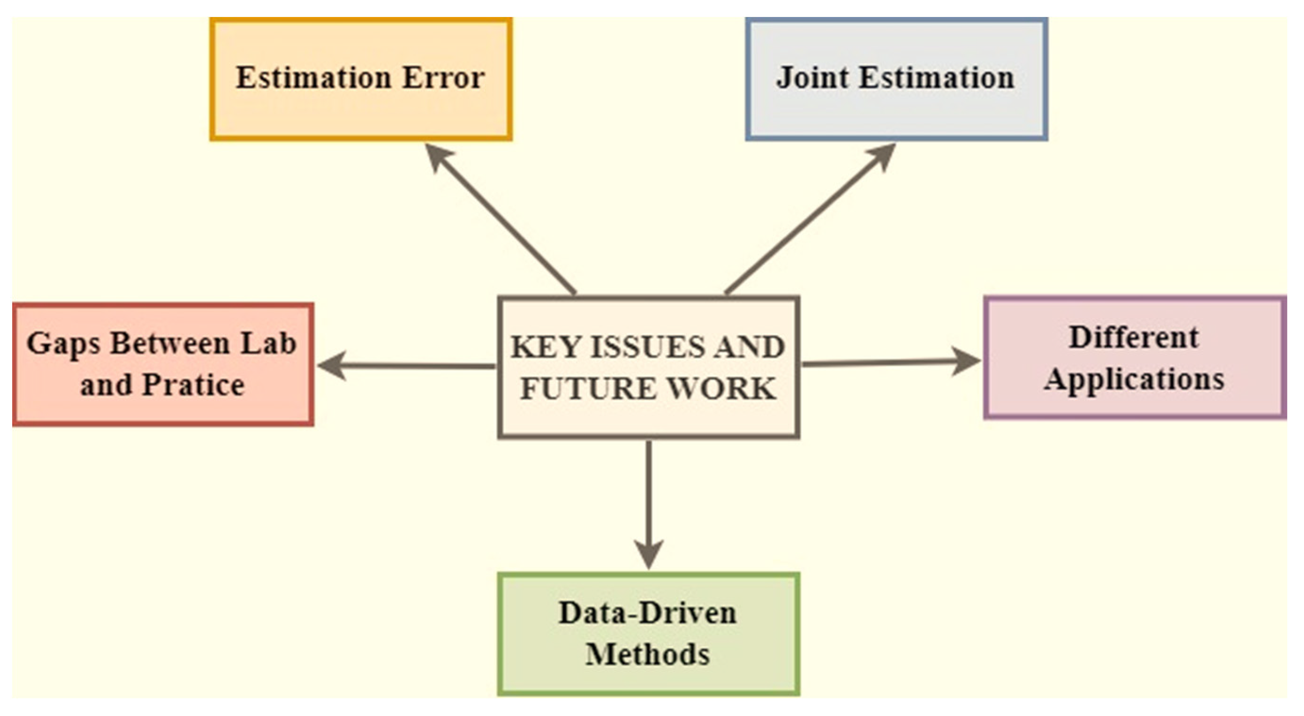
4.7. Key Issue and Future Work

Major concerns and upcoming work a variety of methodologies have been shown to be successful in calculating the SOC condition of LIBs, according to the thorough study in Section 4. To increase estimation accuracy and calculation efficiency for online applications, though, significant progress is still needed. The accurate tracking of SOC in practice is vulnerable by a number of issues since it is a dynamic coupling system.
Future work and important concerns for online SOC estimation. As shown in Figure 7, five viewpoints are used to highlight the challenges and future prospects for SOC estimation from the literature.

4.7.1. Estimation Errors

First of all, no model can accurately capture the non-linear behaviour of LIBs. The hysteresis effect, for instance, makes modelling more uncertain. In order to recreate the dynamics of the battery, a more precise model must be created using the genetic multi-physical modelling technique. Second, in the case of identifying model parameters, the effectiveness of state estimation can be hampered by erroneous values. However, existing Parameter Identification Methods (PIMs) like RLS and Particle Swarm Optimization (PSO) have been shown to be efficient. Thirdly, measurement noise is produced by sensors that measure things like temperature, current and voltage. Finally, as was previously described, the estimating methods also include processes and noise from measurements throughout online applications. It is therefore necessary to enhance or integrate the existing estimating techniques to reduce system mistakes for accurate SOC estimation.

4.7.2. Discrepancies between Laboratory Experimentation and Real-World Application

Still, the majority of investigation for estimating battery SOH and SOC is in the testing stage. In practice, some influencing elements like fluctuating ambient temperature and computational performance have a significant impact on estimating battery SOC and SOH. The LIBs in charging systems or EV operate under challenging settings, with frequent changes in the outside temperature. Since temperature has a substantial impact on the electrochemical dynamics of LIBs, there is a big gap between laboratory study and real-world application. Hence, especially for model-based procedures, the fluctuating thermal data must be taken into account in state estimation methods or battery modelling. Model parameters for model-based approaches must be timeously updated under different operating circumstances. The actual parameter modification will consequently surely make BMS’s computations more difficult. Hence, it is required to perform a sensitivity analysis of the parameters of the battery model with various SOCs in order to identify the key factors that are extremely sensitive to the accuracy of the prediction state. The computational burden of the online application can be decreased by maintaining other insensitive parameters at a constant value or updating them less often. Future research should, therefore, concentrate on SOC and SOH estimation, taking into account the crucial variables of temperature and computing load, as this enables the engineering implementation of laboratory approaches in practice.

4.7.3. Joint Estimation

Specific SOC estimation has been projected using different methods. Limited research has been devoted to the precise integration of SOC estimates. The attainment of somewhat accurate findings can only be achieved by the individual evaluation of each component while disregarding the influence of others. Given the inherent complexity of batteries as dynamic systems, it is important to acknowledge the presence of several interconnected states, such as the interplay between the SOC and other relevant factors. Specifically, due to the substantial impact of capacity degradation on the parameters used in model-based approaches for SOC estimation, the precise forecast of the SOC should be linked to the variation in SOH. Additionally, the accurate beginning number for SOC monitoring can be provided by the dependable SOH estimation. Keep in mind that a joint estimation can result in a higher computational load than a single stage estimation. A promising but difficult effort is the correct co-estimation of SOC. As a result, the future is moving in the direction of more precise and computationally efficient uses of sophisticated methods.

4.7.4. Various Uses

LIBs are being used extensively in EVs because of dependability and a large energy density. While many methods have been established expressly for the estimation of LIBs, the majority of the cutting-edge strategies show low generality when used with different LIB applications. On the one hand, the approaches currently in use focus more on the cell battery than they do on battery modules or battery packs. Realistic meanings in practice include addressing the batteries’ unreliability and offering a precise battery pack. The accurate estimating methods must be investigated for these various applications since, on the opposite end of the spectrum, the LIBs in EVs hold diverse functioning conditions. The battery’s deterioration and the discharged batteries make the battery’s performance more unpredictable and unstable. Therefore, it is crucial to build estimation techniques for the second-hand use of old batteries in various industries. To put it simply, significant research is still needed to increase the consistency and precision of state estimate algorithms used in various LIB applications.

4.7.5. Data-Driven Method

Data-driven methodologies have drawn more focus for the state estimate of LIBs as a result of the development of cloud technology and the accessibility of massive volumes of data monitoring. Based on self-learning properties, data-driven approaches are better able to record the nonlinearity than model-based approaches. It is essential to strengthen two crucial directions, algorithm enhancement and feature selection, or increase the resilience and dependability in order to obtain good performance in actual applications. One way to obtain the real-time and efficient monitoring of several batteries in use is to build smart cloud computing solutions. The real-world data also include complicated operational circumstances, which can help state prediction in practice be more accurate. On the other hand, the training features have a significant effect on how well a machine learning approach functions. The extraction of useful features from a variety of sensor data, including acoustic–ultrasonic, current, temperature, voltage and EIS signals during charging or discharging phases, is therefore crucial. The time taken for estimating SOC must be decreased to achieve online estimation. This necessitates a minimal number of carefully chosen training variables; hence, the development of sophisticated online adaptive learning algorithms with less input is imperative. Combining intelligent approaches with a battery model to account for battery dynamics may be a smart idea in order to increase estimation accuracy. Data-driven approaches should, therefore, be improved in order to encourage the use of machine learning technologies in real-world settings.

5. Conclusions

Prospective SOC estimate systems for EV batteries were examined in this study, with an emphasis on the last few years’ worth of advancements. For SOC estimation, direct measurement methods, adaptive methods, a non-learning observer-based method, learning algorithms and hybrid methods were explored. Finally, the most important concerns and future research were suggested for the practice of the SOC estimation of LIBs. When used in practice, the existing online estimating techniques still have a lot to learn. On the one hand, the battery state estimation is significantly impacted by big mistakes in the battery model and measurement devices. Additionally, as these approaches are often created using laboratory data, a big gap exists between the lab and actual implementations. Because the battery is a nonlinear and dynamic electrochemical system, its status may be readily influenced by a variety of parameters such as the ambient charge–discharge rate and temperature, which makes state assessment in practice more challenging. The complexity of the computations required by data-driven- and model-based approaches, particularly when used with battery packs, surely adds to the computing burden. This review offers the following advice on how to get through the difficulties:
  • A more realistic model that can adapt to the real-world environment’s complexity may be created using the genetic multi-physical modelling approach in conjunction with comparable circuit modelling, temperature, and electrochemical analysis.
  • There is a need to enhance the computational efficiency, estimation accuracy, and practical applications of parameter determination techniques.
  • To increase estimation accuracy, coupled SOH and SOC estimation algorithms can be created. To accomplish a quick state estimation, it is specifically recommended that the EIS model-based and data-driven-based approaches be supplementarily investigated.
  • In order to enable the batteries in various applications, such as the battery pack in electric vehicles and charging systems, estimate techniques should be created.
  • To enhance the estimation of accuracy and efficiency using data-driven approaches, it is important to investigate efficient estimation techniques and feature selection based on sample data. And it is hoped that the big data platform-based data-driven methodologies will be created to enable real-world applications.
In conclusion, developing an SOC estimation taking into account the real-world applications of LIBs is still a popular study area. For diverse application contexts, specific estimating approaches might be chosen. The future study, development, and implementation of practical BMS can hopefully benefit from the highlighted significant issues and standards.

Author Contributions

Writing—original draft preparation, J.S., H.P. and Y.P.; Writing—review and editing, J.S., H.P., Y.P., K.L.H. and M.S.; Supervision, J.S., K.L.H. and M.S. All authors have read and agreed to the published version of the manuscript.

Funding

This work was supported by the Dong-A University research fund.

Institutional Review Board Statement

Not applicable.

Informed Consent Statement

Not applicable.

Data Availability Statement

Not applicable.

Conflicts of Interest

The authors declare no conflict of interest.

References

  1. Jiang, J.; Zhang, C. Fundamentals and Applications of Lithium-Ion Batteries in Electric Drive Vehicles; Wiley: Hoboken, NJ, USA, 2015; pp. 1–300. [Google Scholar]
  2. Pop, V.; Bergveld, H.J.; Danilov, D.; Regtein, P.P. Battery Management Systems: Accurate State-of-Charge Indication for Battery Powered Applications; Springer: Berlin/Heidelberg, Germany, 2008; Volume 9, pp. 1–238. [Google Scholar]
  3. Sung, W.; Shin, C.B. Electrochemical model of a lithium-ion battery implemented into an automotive battery management system. Comput. Chem. Eng. 2015, 76, 87–97. [Google Scholar] [CrossRef]
  4. Xing, Y.; Ma, E.W.; Tsui, K.L.; Pecht, M. Battery Management Systems in Electric and Hybrid Vehicles. Energies 2011, 4, 1840–1857. [Google Scholar] [CrossRef]
  5. Lelie, M.; Braun, T.; Knips, M.; Nordmann, H.; Ringbeck, F.; Zappen, H.; Sauer, D.U. Battery Management System Hardware Concepts: An Overview. Appl. Sci. 2018, 8, 534. [Google Scholar] [CrossRef]
  6. Luo, X.; Kang, L.; Lu, C.; Linghu, J.; Lin, H.; Hu, B. An Enhanced Multicell-to-Multicell Battery Equalizer Based on Bipolar-Resonant LC Converter. Electronics 2021, 10, 293. [Google Scholar] [CrossRef]
  7. Aiello, O. Electromagnetic Susceptibility of Battery Management Systems’ ICs for Electric Vehicles: Experimental Study. Electronics 2020, 9, 510. [Google Scholar] [CrossRef]
  8. Onoda, S.; Emadi, A. PSIM-based modeling of automotive power systems: Conventional, electric, and hybrid electric vehicles. IEEE Trans. Veh. Technol. 2004, 53, 390–400. [Google Scholar] [CrossRef]
  9. Guo, J.M.; Dong, H.X.; Sheng, W.H. Optimal control strategy of regenerative braking energy recovery for electric vehicles. J. Jiangsu Univ. 2018, 39, 132–138. [Google Scholar]
  10. Mao, X.Y. Research on Li-Ion Battery State of Charge and Active Equalization Technology. Master’s Thesis, Nanjing University of Posts and Telecommunications, Nanjing, China, 2020. [Google Scholar]
  11. Martyushev, N.V.; Malozyomov, B.V.; Sorokova, S.N.; Efremenkov, E.A.; Qi, M. Mathematical Modeling of the State of the Battery of Cargo Electric Vehicles. Mathematics 2023, 11, 536. [Google Scholar] [CrossRef]
  12. Wang, E.L. Research on Modeling and SOC Estimation of Lithium-Ion Power Battery for Vehicles. Master’s Thesis, Jiangsu University, Zhenjiang, China, 2020. [Google Scholar]
  13. Xiong, R.; Li, L.; Tian, J. Towards a smarter battery management system: A critical review on battery state of health monitoring methods. J. Power Sources 2018, 405, 18–29. [Google Scholar] [CrossRef]
  14. He, H.; Xiong, R.; Guo, H. Online estimation of model parameters and state-of-charge of LiFePO4 batteries in electric vehicles. Appl. Energy 2012, 89, 413–420. [Google Scholar] [CrossRef]
  15. Watrin, N.; Blunier, B.; Miraoui, A. Review of adaptive systems for lithium batteries State-of-Charge and State-of-Health estimation. In Proceedings of the 2012 IEEE Transportation Electrification Conference and Expo (ITEC), Dearborn, MI, USA, 18–20 June 2012; pp. 1–6. [Google Scholar]
  16. Yang, N.; Zhang, X.; Shang, B.; Li, G. Unbalanced discharging and aging due to temperature differences among the cells in a lithium-ion battery pack with parallel combination. J. Power Sources 2016, 306, 733–741. [Google Scholar] [CrossRef]
  17. Cuma, M.U.; Koroglu, T. A comprehensive review on estimation strategies used in hybrid and battery electric vehicles. Renew. Sustain. Energy Rev. 2015, 42, 517–531. [Google Scholar] [CrossRef]
  18. Zhang, Y.; Song, W.; Lin, S.; Lv, J.; Feng, Z. A critical review on state of charge of batteries. J. Renew Sustain. Energy 2013, 5, 021403. [Google Scholar]
  19. Chang, W.-Y. The state of charge estimating methods for battery: A review. ISRN Appl. Math. 2013, 2013, 953792. [Google Scholar] [CrossRef]
  20. Alcaraz, C.; Cumplido, J.; Trivino, A. OCPP in the spotlight: Threats and countermeasures for electric vehicle charging infrastructures 4.0. Int. J. Inf. Secur. 2023, 22, 1395–1421. [Google Scholar] [CrossRef]
  21. Ko, Y.; Choi, W. A New SOC Estimation for LFP Batteries: Application in a 10 Ah Cell (HW 38120 L/S) as a Hysteresis Case Study. Electronics 2021, 10, 705. [Google Scholar] [CrossRef]
  22. Doridant, A.; Abouda, K.; Givelin, P.; Thibaud, B. Battery Management System Demonstrator Board design using EMC System simulation. In Proceedings of the International Symposium on Electromagnetic Compatibility—EMC, EUROPE, Barcelona, Spain, 2–6 September 2019; pp. 427–432. [Google Scholar]
  23. Kang, T.; Park, S.; Lee, P.Y.; Cho, I.H.; Yoo, K.; Kim, J. Thermal Analysis of a Parallel-Configured Battery Pack (1S18P) Using 21700 Cells for a Battery-Powered Train. Electronics 2020, 9, 447. [Google Scholar] [CrossRef]
  24. Abbas, M.; Cho, I.; Kim, J. Analysis of High-Power Charging Limitations of a Battery in a Hybrid Railway System. Electronics 2020, 9, 212. [Google Scholar] [CrossRef]
  25. Arnieri, E.; Boccia, L.; Amoroso, F.; Amendola, G.; Cappuccino, G. Improved Efficiency Management Strategy for Battery-Based Energy Storage Systems. Electronics 2019, 8, 1459. [Google Scholar] [CrossRef]
  26. Lee, S.; Kim, J. Power Capability Analysis of Lithium Battery and Supercapacitor by Pulse Duration. Electronics 2019, 8, 1395. [Google Scholar] [CrossRef]
  27. Uno, M.; Ueno, T.; Yoshino, K. Cell Voltage Equalizer Using a Selective Voltage Multiplier with a Reduced Selection Switch Count for Series-Connected Energy Storage Cells. Electronics 2019, 8, 1303. [Google Scholar] [CrossRef]
  28. Lee, H.; Park, J.; Kim, J. Incremental Capacity Curve Peak Points-Based Regression Analysis for the State-of-Health Prediction of a Retired LiNiCoAlO2 Series/Parallel Configured Battery Pack. Electronics 2019, 8, 1118. [Google Scholar] [CrossRef]
  29. Martyushev, N.V.; Malozyomov, B.V.; Khalikov, I.H.; Kukartsev, V.A.; Kukartsev, V.V.; Tynchenko, V.S.; Tynchenko, Y.A.; Qi, M. Review of Methods for Improving the Energy Efficiency of Electrified Ground Transport by Optimizing Battery Consumption. Energies 2023, 16, 729. [Google Scholar] [CrossRef]
  30. Liang, Y.; Zhao, C.Z.; Yuan, H.; Chen, Y.; Zhang, W.; Huang, J.Q.; Yu, D.; Liu, Y.; Titirici, M.M.; Chueh, Y.L.; et al. A review of rechargeable batteries for portable electronic devices. InfoMat 2019, 1, 6–32. [Google Scholar] [CrossRef]
  31. Shukla, A. Nickel-based rechargeable batteries. J. Power Sources 2001, 100, 125–148. [Google Scholar] [CrossRef]
  32. Basic to Advanced Battery Information from Battery University. Available online: https://batteryuniversity.com/ (accessed on 5 June 2022).
  33. Hannan, M.A.; Hoque, M.M.; Hussain, A.; Yusof, Y.; Ker, P.J. State-of-the-Art and Energy Management System of Lithium-Ion Batteries in Electric Vehicle Applications: Issues and Recommendations. IEEE Access 2018, 6, 19362–19378. [Google Scholar] [CrossRef]
  34. Xiong, R.; Tian, J.; Mu, H.; Wang, C. A systematic model-based degradation behavior recognition and health monitoring method for lithium-ion batteries. Appl. Energy 2017, 207, 372–383. [Google Scholar] [CrossRef]
  35. Daud, M.Z.; Mohamed, A.; Hannan, M.A. A novel coordinated control strategy considering power smoothing for a hybrid photovoltaic/battery energy storage system. J. Cent. South Univ. 2016, 23, 394–404. [Google Scholar] [CrossRef]
  36. Zhang, Z.; Zhang, Q.; Chen, Y.; Bao, J.; Zhou, X.; Xie, Z.; Wei, J.; Zhou, Z. The First Introduction of Graphene to Rechargeable Li-CO2Batteries. Angew. Chem. Int. Ed. 2015, 54, 6550–6553. [Google Scholar] [CrossRef]
  37. Cui, Y.; Mahmoud, M.M.; Rohde, M.; Ziebert, C.; Seifert, H.J. Thermal and ionic conductivity studies of lithium aluminum germanium phosphate solid-state electrolyte. Solid State Ion. 2016, 289, 125–132. [Google Scholar] [CrossRef]
  38. Li, S.; Xue, Y.; Cui, X.; Geng, S.; Huang, Y. Effect of sulfolane and lithium bis(oxalato)borate-based electrolytes on the performance of spinel LiMn2O4 cathodes at 55 °C. Ionics 2015, 22, 797–801. [Google Scholar] [CrossRef]
  39. Tarascon, J.M.; Recham, N.; Armand, M.; Chotard, J.N.; Barpanda, P.; Walker, W.; Dupont, L. Hunting for Better Li-Based Electrode Materials via Low Temperature Inorganic Synthesis. Chem. Mater. 2009, 22, 724–739. [Google Scholar] [CrossRef]
  40. Omar, N.; Verbrugge, B.; Mulder, G.; Van den Bossche, P.; Van Mierlo, J.; Daowd, M.; Dhaens, M.; Pauwels, S. Evaluation of performance characteristics of various lithium-ion batteries for use in BEV application. In Proceedings of the Vehicle Power and Propulsion Conference, Lille, France, 1–3 September 2010; pp. 1–6. [Google Scholar]
  41. Makimura, Y.; Sasaki, T.; Nonaka, T.; Nishimura, Y.F.; Uyama, T.; Okuda, C.; Itou, Y.; Takeuchi, Y. Factors Affecting Cycling Life of LiNi0.8Co0.15Al0.05O2for lithium-ion Batteries. J. Mater. Chem. A Mater. Energy Sustain. 2016, 4, 8350–8358. [Google Scholar] [CrossRef]
  42. Labrini, M.; Scheiba, F.; Almaggoussi, A.; Larzek, M.; Braga, M.H.; Ehrenberg, H.; Saadoune, I. Delithiated LiyCo0.8Ni0.1Mn0.1O2 cathode materials for lithium-ion batteries: Structural, magnetic and electrochemical studies. Solid State Ion. 2016, 289, 207–213. [Google Scholar] [CrossRef]
  43. Zeng, X.; Li, J.; Liu, L. Solving spent lithium-ion battery problems in China: Opportunities and challenges. Renew. Sustain. Energy Rev. 2015, 52, 1759–1767. [Google Scholar] [CrossRef]
  44. Canilang, H.M.O.; Caliwag, A.C.; Lim, W. Design, Implementation, and Deployment of Modular Battery Management System for IIoT-Based Applications. IEEE Access 2022, 10, 109008–109028. [Google Scholar] [CrossRef]
  45. Andrea, D. Battery Management Systems for Large Lithium-ion Battery Packs. Artech House. 2023. Available online: https://books.google.com/books/about/Battery_Management_Systems_for_Large_Lit.html?id=nivOtAEACAAJ (accessed on 15 July 2023).
  46. Frost, D.F.; Howey, D.A. Completely Decentralized Active Balancing Battery Management System. IEEE Trans. Power Electron. 2018, 33, 729–738. [Google Scholar] [CrossRef]
  47. Sun, F.; Markötter, H.; Manke, I.; Hilger, A.; Kardjilov, N.; Banhart, J. Three-Dimensional Visualization of Gas Evolution and Channel Formation inside a Lithium-Ion Battery. ACS Appl. Mater. Interfaces 2016, 8, 7156–7164. [Google Scholar] [CrossRef]
  48. Shim, J.; Kostecki, R.; Richardson, T.; Song, X.; Striebel, K.A. Electrochemical analysis for cycle performance and capacity fading of a lithium-ion battery cycled at elevated temperature. J. Power Sources 2002, 112, 222–230. [Google Scholar] [CrossRef]
  49. Wang, G.; Gao, Q.; Yan, Y.; Wang, Y. Thermal Management Optimization of a Lithium-Ion Battery Module with Graphite Sheet Fins and Liquid Cold Plates. Automot. Innov. 2020, 3, 336–346. [Google Scholar] [CrossRef]
  50. Shahid, S.; Agelin-Chaab, M. Experimental and numerical studies on air cooling and temperature uniformity in a battery pack. Int. J. Energy Res. 2018, 42, 2246–2262. [Google Scholar] [CrossRef]
  51. Huang, R.; Li, Z.; Hong, W.; Wu, Q.; Yu, X. Experimental and numerical study of PCM thermophysical parameters on lithium-ion battery thermal management. Energy Rep. 2020, 6, 8–19. [Google Scholar] [CrossRef]
  52. Vulligaddala, V.B.; Vernekar, S.; Singamla, S.; Adusumalli, R.K.; Ele, V.; Brandl, M.; Srinivas, M.B. A 7-Cell, Stackable, Li-Ion Monitoring and Active/Passive Balancing IC With In-Built Cell Balancing Switches for Electric and Hybrid Vehicles. IEEE Trans. Ind. Inform. 2020, 16, 3335–3344. [Google Scholar] [CrossRef]
  53. How, D.N.; Hannan, M.A.; Lipu, M.H.; Ker, P.J. State of Charge Estimation for Lithium-Ion Batteries Using Model-Based and Data-Driven Methods: A Review. IEEE Access 2019, 7, 136116–136136. [Google Scholar] [CrossRef]
  54. Omariba, Z.B.; Zhang, L.; Sun, D. Review of Battery Cell Balancing Methodologies for Optimizing Battery Pack Performance in Electric Vehicles. IEEE Access 2019, 7, 129335–129352. [Google Scholar] [CrossRef]
  55. Balasingam, B.; Ahmed, M.; Pattipati, K. Battery Management Systems—Challenges and Some Solutions. Energies 2020, 13, 2825. [Google Scholar] [CrossRef]
  56. Rahimi-Eichi, H.; Ojha, U.; Baronti, F.; Chow, M.-Y. Battery Management System: An Overview of Its Application in the Smart Grid and Electric Vehicles. IEEE Ind. Electron. Mag. 2013, 7, 4–16. [Google Scholar] [CrossRef]
  57. Lu, L.; Han, X.; Li, J.; Hua, J.; Ouyang, M. A review on the key issues for lithium-ion battery management in electric vehicles. J. Power Sources 2013, 226, 272–288. [Google Scholar] [CrossRef]
  58. Alavi, S.M.M.; Samadi, M.F.; Saif, M. Diagnostics in Lithium-Ion Batteries: Challenging Issues and Recent Achievements. In Integration of Practice-Oriented Knowledge Technology: Trends and Prospectives; Fathi, M., Ed.; Springer: Berlin/Heidelberg, Germany, 2013; pp. 277–291. [Google Scholar]
  59. See, K.W.; Wang, G.; Zhang, Y.; Wang, Y.; Meng, L.; Gu, X.; Zhang, N.; Lim, K.C.; Zhao, L.; Xie, B. Critical review and functional safety of a battery management system for large-scale lithium-ion battery pack technologies. Int. J. Coal Sci. Technol. 2022, 9, 36. [Google Scholar] [CrossRef]
  60. IEC 62619; Safety Requirements for Secondary Lithium Cells and Batteries, for Use in Industrial Applications. International Electrotechnical Commission: London, UK, 2022. Available online: https://webstore.iec.ch/publication/64073 (accessed on 15 July 2023).
  61. UL 9540; Energy Storage System (ESS) Requirements—Evolving to Meet Industry and Regulatory Needs. Authored by Laurie B. Florence and Howard D. Hopper. FPE: Village, IL, USA, 20 May 2020. Available online: https://www.ul.com/services/energy-storage-system-testing-and-certification (accessed on 15 July 2023).
  62. UL 1973; Batteries for Use in Stationary, Vehicle Auxiliary Power and Light Electric Rail (LER) Applications. Authored by Laurie B. Florence and Howard D. Hopper. FPE: Village, IL, USA, 20 May 2020. Available online: https://batterystandards.info/standard/ul-1973 (accessed on 15 July 2023).
  63. NAVSEA S9310; Naval Lithium Battery Safety Program. NAVSEA: Carderock, MD, USA, 2015. Available online: https://navysbir.com/n21_1/Topic-N211-033-Reference_Document_S9310-AQ-SAF-010-Rev3.pdf (accessed on 15 July 2023).
  64. IEEE 1679.1; Characterization and Evaluation of Lithium-Based Batteries in Stationary Applications. IEEE: New York, NY, USA, 2017. Available online: https://standards.ieee.org/ieee/1679.1/7222/ (accessed on 15 July 2023).
  65. Ng, K.S.; Moo, C.S.; Chen, Y.P.; Hsieh, Y.C. State-of-charge estimation for lead-acid batteries based on dynamic open-circuit voltage. In Proceedings of the 2nd IEEE International Power and Energy Conference (PECon ’08), Johor Bahru, Malaysia, 1–3 December 2008; pp. 972–976. [Google Scholar]
  66. Anbuky, A.H.; Pascoe, P.E. VRLA battery state-of-charge estimation in telecommunication power systems. IEEE Trans. Ind. Electron. 2000, 47, 565–573. [Google Scholar] [CrossRef]
  67. Sato, S.; Kawamura, A. A new estimation method of state of charge using terminal voltage and internal resistance for lead acid battery. In Proceedings of the Power Conversion Conference, Osaka, Japan, 2–5 April 2002; pp. 565–570. [Google Scholar]
  68. Barcellona, S.; Grillo, S.; Piegari, L. A simple battery model for ev range prediction: Theory and experimental validation. In Proceedings of the 2016 International Conference on Electrical Systems for Aircraft, Railway, Ship Propulsion and Road Vehicles & International Transportation Electrification Conference (ESARS-ITEC), Toulouse, France, 2–4 November 2016; pp. 1–7. [Google Scholar]
  69. Westerhoff, U.; Kroker, T.; Kurbach, K.; Kurrat, M. Electrochemical impedance spectroscopy-based estimation of the state of charge of lithium-ion batteries. J. Energy Storage 2016, 8, 244–256. [Google Scholar] [CrossRef]
  70. Shili, S.; Sari, A.; Hijazi, A.; Venet, P. Online lithium-ion batteries health monitoring using balancing circuits. In Proceedings of the 2017 IEEE International Conference on Industrial Technology (ICIT), Toronto, ON, Canada, 22–25 March 2017; pp. 484–488. [Google Scholar]
  71. Mohammed, N.; Saif, A.M. Programmable logic controller based lithium-ion battery management system for accurate state of charge estimation. Comput. Electr. Eng. 2021, 93, 107306. [Google Scholar] [CrossRef]
  72. Truchot, C.; Dubarry, M.; Liaw, B.Y. State-of-charge estimation and uncertainty for lithium-ion battery strings. Appl. Energy 2014, 119, 218–227. [Google Scholar] [CrossRef]
  73. Zhang, S.; Guo, X.; Dou, X.; Zhang, X. A data-driven coulomb counting method for state of charge calibration and estimation of lithium-ion battery. Sustain. Energy Technol. Assess. 2020, 40, 100752. [Google Scholar] [CrossRef]
  74. Xu, L.; Wang, J.; Chen, Q. Kalman filtering state of charge estimation for battery management system based on a stochastic fuzzy neural network battery model. Energy Convers. Manag. 2012, 53, 33–39. [Google Scholar] [CrossRef]
  75. Ting, T.O.; Man, K.L.; Lim, E.G.; Leach, M. Tuning of Kalman Filter Parameters via Genetic Algorithm for State-of-Charge Estimation in Battery Management System. Sci. World J. 2014, 2014, 176052. [Google Scholar] [CrossRef] [PubMed]
  76. Urbain, M.; Raël, S.; Davat, B.; Desprez, P. State Estimation of a Lithium-Ion Battery Through Kalman Filter. In Proceedings of the IEEE Power Electronics Specialists Conference, Orlando, FL, USA, 17–21 June 2007; pp. 2804–2810. [Google Scholar]
  77. Yatsui, M.W.; Bai, H. Kalman filter based state-of-charge estimation for lithium-ion batteries in hybrid electric vehicles using pulse charging. In Proceedings of the IEEE Vehicle Power and Propulsion Conference, Chicago, IL, USA, 6–9 September 2011. [Google Scholar]
  78. Jokić, I.; Zečević, Ž.; Krstajić, B. State-of-charge estimation of lithium-ion batteries using extended Kalman filter and unscented Kalman filter. In Proceedings of the 23rd International Scientific-Professional Conference on Information Technology (IT), Zabljak, Montenegro, 19–24 February 2018; pp. 1–4. [Google Scholar]
  79. Plett, G.L. Extended Kalman filtering for battery management systems of LiPB-based HEV battery packs. J. Power Sources 2004, 134, 277–292. [Google Scholar] [CrossRef]
  80. Sassi, H.B.; Errahimi, F.; ES-Sbai, N. State of charge estimation by multi-innovation unscented Kalman filter for vehicular applications. J. Energy Storage 2020, 32, 101978. [Google Scholar] [CrossRef]
  81. Meng, Z.; Xia, X.; Xu, R.; Liu, W.; Ma, J. HYDRO-3D: Hybrid Object Detection and Tracking for Cooperative Perception Using 3D LiDAR. IEEE Trans. Intell. Veh. 2023, 8, 4069–4080. [Google Scholar] [CrossRef]
  82. Hu, X.; Sun, F.; Zou, Y. Comparison between two model-based algorithms for Li-ion battery SOC estimation in electric vehicles. Simul. Model. Pract. Theory 2013, 34, 1–11. [Google Scholar] [CrossRef]
  83. Lee, S.J.; Kim, J.H.; Lee, J.M.; Cho, B.H. The State and Parameter Estimation of an Li-Ion Battery Using a New OCV-SOC Concept. In Proceedings of the 2007 IEEE Power Electronics Specialists Conference, Orlando, FL, USA, 17–21 June 2007. [Google Scholar]
  84. Chen, Z.; Fu, Y.; Mi, C.C. State of Charge Estimation of Lithium-Ion Batteries in Electric Drive Vehicles Using Extended Kalman Filtering. IEEE Trans. Veh. Technol. 2013, 62, 1020–1030. [Google Scholar] [CrossRef]
  85. Mastali, M.; Vazquez-Arenas, J.; Fraser, R.; Fowler, M.; Afshar, S.; Stevens, M. Battery State of the Charge Estimation Using Kalman Filtering. J. Power Sources 2013, 239, 294–307. [Google Scholar] [CrossRef]
  86. He, W.; Williard, N.; Chen, C.; Pecht, M. State of charge estimation for electric vehicle batteries using unscented kalman filtering. Microelectron. Reliab. 2013, 53, 840–847. [Google Scholar] [CrossRef]
  87. Sun, F.; Hu, X.; Zou, Y.; Li, S. Adaptive unscented Kalman filtering for state of charge estimation of a lithium-ion battery for electric vehicles. Energy 2011, 36, 3531–3540. [Google Scholar] [CrossRef]
  88. Li, J.; Barillas, J.K.; Guenther, C.; Danzer, M.A. A Comparative Study of State of Charge Estimation Algorithms for LiFePO4 Batteries Used in Electric Vehicles. J. Power Sources 2013, 230, 244–250. [Google Scholar] [CrossRef]
  89. Gao, M.; Liu, Y.; He, Z. Battery state of charge online estimation based on particle filter. In Proceedings of the 4th International Congress on Image and Signal Processing, Shanghai, China, 15–17 October 2011. [Google Scholar]
  90. He, Y.; Liu, X.; Zhang, C.; Chen, Z. A new model for State-of-Charge (SOC) estimation for high-power Li-ion batteries. Appl. Energy 2013, 101, 808–814. [Google Scholar] [CrossRef]
  91. Zhang, Y.; Zhang, C.; Zhang, X. State-of-charge estimation of the lithium-ion battery system with time-varying parameter for hybrid electric vehicles. IET Control. Theory Appl. 2014, 8, 160–167. [Google Scholar] [CrossRef]
  92. Charkhgard, M.; Zarif, M.H. Design of adaptive H filter for implementing on state-of-charge estimation based on battery state-of-charge-varying modelling. IET Power Electron. 2015, 8, 1825–1833. [Google Scholar] [CrossRef]
  93. Eddahech, A.; Briat, O.; Vinassa, J.M. Adaptive voltage estimation for EV Li-ion cell based on artificial neural networks state-of-charge meter. In Proceedings of the IEEE International Symposium on Industrial Electronics, Hangzhou, China, 28–31 May 2012; pp. 1318–1324. [Google Scholar]
  94. Kim, I.S. Nonlinear State of Charge Estimator for Hybrid Electric Vehicle Battery. IEEE Trans. Power Electron. 2008, 23, 2027–2034. [Google Scholar]
  95. Chen, X.; Shen, W.; Cao, Z.; Kapoor, A. A novel approach for state of charge estimation based on adaptive switching gain sliding mode observer in electric vehicles. J. Power Sources 2014, 246, 667–678. [Google Scholar] [CrossRef]
  96. Chen, X.; Shen, W.; Cao, Z.; Kapoor, A. Sliding mode observer for state of charge estimation based on battery equivalent circuit in electric vehicles. Aust. J. Electr. Electron. Eng. 2012, 9, 601–606. [Google Scholar]
  97. Xu, C.; Zhang, E.; Yan, S.; Jiang, K.; Wang, K.; Wang, Z.; Cheng, S. State of charge estimation for liquid metal battery based on an improved sliding mode observer. J. Energy Storage 2022, 45, 103701. [Google Scholar] [CrossRef]
  98. Chen, M.; Han, F.; Shi, L.; Feng, Y.; Xue, C.; Gao, W.; Xu, J. Sliding Mode Observer for State-of-Charge Estimation Using Hysteresis-Based Li-Ion Battery Model. Energies 2022, 15, 2658. [Google Scholar] [CrossRef]
  99. Ma, Y.; Xu, D.; Yang, W.; Pan, T.; Ding, Y. Fractional Order Terminal Sliding Mode Observer for State of Charge Estimation of Lithium-Ion Battery. In Proceedings of the 2023 IEEE 12th Data Driven Control and Learning Systems Conference (DDCLS), Xiangtan, China, 12–14 May 2023; pp. 551–556. [Google Scholar]
  100. Xu, J.; Mi, C.C.; Cao, B.; Deng, J.; Chen, Z.; Li, S. The state of charge estimation of lithium-ion batteries based on a proportional-integral observer. IEEE Trans. Veh. Technol. 2014, 63, 1614–1621. [Google Scholar]
  101. Chen, T.; Huo, M.; Yang, X.; Wen, R. A Fast Lithium-Ion Battery Impedance and SOC Estimation Method Based on Two-Stage PI Observer. World Electr. Veh. J. 2021, 12, 108. [Google Scholar] [CrossRef]
  102. Amir, U.; Tao, L.; Zhang, X.; Saeed, M.; Hussain, M. A Novel SOC Estimation Method for Lithium Ion Battery Based on Improved Adaptive PI Observer. In Proceedings of the 2018 IEEE International Conference on Electrical Systems for Aircraft Railway, Ship Propulsion and Road Vehicles & International Transportation Electrification Conference (ESARS-ITEC), Nottingham, UK, 7–9 November 2018; pp. 1–5. [Google Scholar]
  103. Boizot, N.; Busvelle, E.; Gauthier, J.-P. An adaptive high-gain observer for nonlinear systems. Automatica 2010, 46, 1483–1488. [Google Scholar] [CrossRef]
  104. Xu, F.; Wang, Y.; Luo, X. Soft sensor for inputs and parameters using nonlinear singular state Observer in chemical processes. Chin. J. Chem. Eng. 2013, 21, 1038–1047. [Google Scholar] [CrossRef]
  105. Kim, I.-S. The novel state of charge estimation method for lithium battery using sliding mode observer. J. Power Sources 2006, 16, 584–590. [Google Scholar] [CrossRef]
  106. Xia, B.; Chen, C.; Tian, Y.; Sun, W.; Xu, Z.; Zheng, W. A novel method for state of charge estimation of lithium-ion batteries using a nonlinear observer. J. Power Sources 2014, 270, 359–366. [Google Scholar] [CrossRef]
  107. Liu, Y.; Ma, R.; Pang, S.; Xu, L.; Zhao, D.; Wei, J.; Huangfu, Y.; Gao, F. A Nonlinear Observer SOC Estimation Method Based on Electrochemical Model for Lithium-Ion Battery. IEEE Trans. Ind. Appl. 2021, 57, 1094–1104. [Google Scholar] [CrossRef]
  108. Chen, Z.; Qiu, S.; Masrur, M.A.; Murphey, Y.L. Battery state of charge estimation based on a combined model of extended Kalman filter and neural networks. In Proceedings of the 2011 International Joint Conference on Neural Networks, San Jose, CA, USA, 31 July–5 August 2011; pp. 2156–2163. [Google Scholar]
  109. Charkhgard, M.; Farrokhi, M. State-of-charge estimation for lithium-ion batteries using neural networks and EKF. IEEE Trans Ind Electron 2010, 57, 4178–4187. [Google Scholar] [CrossRef]
  110. Liu, R.-H.; Sun, Y.-K.; Ji, X.-F. Battery state of charge estimation for electric vehicle based on neural network. In Proceedings of the IEEE 3rd International Conference on Communication Software and Networks, Xi’an, China, 27–29 May 2011. [Google Scholar]
  111. Chang, W.Y. State of charge estimation for LiFePO4 battery using artificial neural network. Int. Rev. Electr. Eng. 2012, 7, 5874–5880. [Google Scholar]
  112. Weigert, T.; Tian, Q.; Lian, K. State-of-charge prediction of batteries and battery-supercapacitor hybrids using artificial neural networks. J. Power Sources 2011, 196, 4061–4066. [Google Scholar] [CrossRef]
  113. Linda, O.; William, E.J.; Huff, M.; Manic, M.; Gupta, V.; Nance, J.; Hess, H.; Rufus, F.; Thakker, A.; Govar, J. Intelligent neural network implementation for SOCI development of Li/CFx batteries. In Proceedings of the 2nd International Symposium on Resilient Control Systems (ISRCS ’09), Idaho Falls, ID, USA, 11–13 August 2009; pp. 57–62. [Google Scholar]
  114. Tong, S.; Lacap, J.H.; Park, J.W. Battery state of charge estimation using a load-classifying neural network. J. Energy Storage 2016, 7, 236–243. [Google Scholar] [CrossRef]
  115. Dang, X.; Yan, L.; Xu, K.; Wu, X.; Jiang, H.; Sun, H. Open-circuit voltage-based state of charge estimation of lithium-ion battery using dual neural network fusion battery model. Electrochim. Acta 2016, 188, 356–366. [Google Scholar] [CrossRef]
  116. Hossain Lipu, M.S.; Hannan, M.A.; Hussain, A.; Saad, M.H.M. Optimal BP neural network algorithm for state of charge estimation of lithium-ion battery using PSO with PCA feature selection. J. Renew. Sustain. Energy 2017, 9, 064102. [Google Scholar] [CrossRef]
  117. Chen, J.; Ouyang, Q.; Xu, C.; Su, H. Neural network-based state of charge observer design for lithium-ion batteries. IEEE Trans. Control Syst. Technol. 2017, 26, 313–320. [Google Scholar] [CrossRef]
  118. Lipu, M.S.H.; Hannan, M.A.; Hussain, A.; Saad, M.H.M.; Ayob, A.; Blaabjerg, F. State of charge estimation for lithium-ion battery using recurrent NARX neural network model based lighting search algorithm. IEEE Access 2018, 6, 28150–28161. [Google Scholar] [CrossRef]
  119. Hannan, M.A.; Lipu, M.S.H.; Hussain, A.; Ker, P.J.; Mahlia, T.M.I.; Mansor, M.; Ayob, A.; Saad, M.H.; Dong, Z.Y. Toward enhanced State of charge estimation of Lithium-ion Batteries Using optimized Machine Learning techniques. Sci. Rep. 2020, 10, 4687. [Google Scholar] [CrossRef]
  120. Xia, B.; Cui, D.; Sun, Z.; Lao, Z.; Zhang, R.; Wang, W.; Sun, W.; Lai, Y.; Wang, M. State of charge estimation of lithium-ion batteries using optimized Levenberg-Marquardt wavelet neural network. Energy 2018, 153, 694–705. [Google Scholar] [CrossRef]
  121. Yang, F.; Song, X.; Xu, F.; Tsui, K.-L. State-of-charge estimation of lithium-ion batteries via long short-term memory network. IEEE Access 2019, 7, 53792–53799. [Google Scholar] [CrossRef]
  122. Liu, Y.; Shu, X.; Yu, H.; Shen, J.; Zhang, Y.; Liu, Y.; Chen, Z. State of charge prediction framework for lithium-ion batteries incorporating long short-term memory network and transfer learning. J. Energy Storage 2021, 37, 102494. [Google Scholar] [CrossRef]
  123. Chen, Y.; Li, C.; Chen, S.; Ren, H.; Gao, Z. A combined robust approach based on auto-regressive long short-term memory network and moving horizon estimation for state-of-charge estimation of lithium-ion batteries. Int. J. Energy Res. 2021, 45, 12838–12853. [Google Scholar] [CrossRef]
  124. Lei, X.; Chan, C.C.; Liu, K.; Ma, L. Battery state of charge estimation based on Neural-Network for electric vehicles. Trans. China Electrotech. Tech. Soc. 2007, 22, 155–160. [Google Scholar]
  125. Zhang, L.; Zheng, M.; Du, D.; Li, Y.; Fei, M.; Guo, Y.; Li, K. State-of-Charge Estimation of Lithium-Ion Battery Pack Based on Improved RBF Neural Networks. Complexity 2020, 2020, 8840240. [Google Scholar] [CrossRef]
  126. Salkind, A.J.; Fennie, C.; Singh, P.; Atwater, T.; Reisner, D.E. Determination of state-of-charge and state-of-health of batteries by fuzzy logic methodology. J. Power Sources 1999, 80, 293–300. [Google Scholar] [CrossRef]
  127. Singh, P.; Vinjamuri, R.; Wang, X.; Reisner, D. Design and implementation of a fuzzy logic-based state-of-charge meter for Li-ion batteries used in portable defibrillators. J. Power Sources 2006, 162, 829–836. [Google Scholar] [CrossRef]
  128. Wu, X.; Mi, L.; Tan, W.; Qin, J.L.; Zhao, M.N. State of charge (SOC) estimation of NiMH battery based on least square support vector machines. Adv. Mater. Res. 2011, 211, 1204–1209. [Google Scholar] [CrossRef]
  129. Álvarez Antón, J.C.; García Nieto, P.J.; de Cos Juez, F.J.; Sánchez Lasheras, F.; González Vega, M.; Roqueñí Gutiérrez, M.N. Battery state-of-charge estimator using the SVM technique. Appl. Math. Model 2013, 37, 6244–6253. [Google Scholar] [CrossRef]
  130. Chen, Y.; Long, B.; Lei, X. The battery state of charge estimation based weighted least squares support vector machine. In Proceedings of the 2011 Asia-Pacific Power and Energy Engineering Conference, Wuhan, China, 25–28 March 2011; Volume 1, pp. 1–4. [Google Scholar]
  131. Zheng, Y.; Lu, L.; Han, X.; Li, J.; Ouyang, M. LiFePO4 battery pack capacity estimation for electric vehicles based on charging cell voltage curve transformation. J. Power Sources 2013, 226, 33–41. [Google Scholar] [CrossRef]
  132. Xu, J.; Cao, B.; Chen, Z.; Zou, Z. An online state of charge estimation method with reduced prior battery testing information. J. Electr. Power Energy Syst. 2014, 63, 178–184. [Google Scholar] [CrossRef]
  133. Chemali, E.; Kollmeyer, P.J.; Preindl, M.; Ahmed, R.; Emadi, A.; Kollmeyer, P. Long Short-Term Memory Networks for Accurate State-of-Charge Estimation of Li-ion Batteries. IEEE Trans. Ind. Electron. 2018, 65, 6730–6739. [Google Scholar] [CrossRef]
  134. How, D.N.; Hannan, M.; Lipu, M.H.; Sahari, K.S.; Ker, P.J.; Muttaqi, K.M. State-of-charge estimation of li-ion battery in electric vehicles: A deep neural network approach. IEEE Trans. Ind. Appl. 2020, 56, 5565–5574. [Google Scholar] [CrossRef]
  135. Yang, F.; Li, W.; Li, C.; Miao, Q. State-of-charge estimation of lithium-ion batteries based on gated recurrent neural network. Energy 2019, 175, 66–75. [Google Scholar] [CrossRef]
  136. Song, X.; Yang, F.; Wang, D.; Tsui, K.-L. Combined CNN-LSTM Network for State-of-Charge Estimation of Lithium-Ion Batteries. IEEE Access 2019, 7, 88894–88902. [Google Scholar] [CrossRef]
  137. Wang, J.; Cao, B.; Chen, Q.; Wang, F. Combined state of charge estimator for electric vehicle battery pack. Control. Eng. Pract. 2007, 15, 1569–1576. [Google Scholar] [CrossRef]
  138. Kim, J.; Cho, B.H. State-of-charge estimation and state-of-health prediction of a Li-ion degraded battery based on an EKF combined with a per-unit system. IEEE Trans. Veh. Technol. 2011, 60, 4249–4260. [Google Scholar] [CrossRef]
  139. Propp, K.; Marinescu, M.; Auger, D.J.; O’Neill, L.; Fotouhi, A.; Somasundaram, K.; Offer, G.J.; Minton, G.; Longo, S.; Wild, M.; et al. Multi temperature state-dependent equivalent circuit discharge model for lithium-sulfur batteries. J. Power Sources 2016, 328, 289–299. [Google Scholar] [CrossRef]
  140. Dong, G.; Wei, J.; Zhang, C.; Chen, Z. Online state of charge estimation and open circuit voltage hysteresis modeling of LiFePO4 battery using invariant imbedding method. Appl. Energy 2016, 162, 163–171. [Google Scholar] [CrossRef]
  141. Zhang, J.; Lee, J. A review on prognostics and health monitoring of Li-ion battery. J. Power Sources 2011, 196, 6007–6014. [Google Scholar] [CrossRef]
  142. Kroeze, R.C.; Krein, P.T. Electrical battery model for use in dynamic electric vehicle simulations. In Proceedings of the 2008 IEEE Power Electronics Specialists Conference, Rhodes, Greece, 15–19 June 2008; pp. 1336–1342. [Google Scholar]
  143. Hu, X.; Li, S.; Peng, H. A comparative study of equivalent circuit models for Li-ion batteries. J. Power Sources 2012, 198, 359–367. [Google Scholar] [CrossRef]
  144. Bi, Z.; Kan, T.; Mi, C.C.; Zhang, Y.; Zhao, Z.; Keoleian, G.A. A review of wireless power transfer for electric vehicles: Prospects to enhance sustainable mobility. Appl. Energy 2016, 179, 413–425. [Google Scholar] [CrossRef]
  145. Yuan, X.; Liu, H.; Zhang, J. Lithium-Ion Batteries: Advanced Materials and Technologies; CRC Press: Boca Raton, FL, USA, 2011. [Google Scholar]
  146. Tanim, T.R.; Rahn, C.D. Aging formula for lithium ion batteries with solid electrolyte interphase layer growth. J. Power Sources 2015, 294, 239–247. [Google Scholar] [CrossRef]
  147. Lavigne, L.; Sabatier, J.; Francisco, J.M.; Guillemard, F.; Noury, A. Lithium-ion Open Circuit Voltage (OCV) curve modelling and its ageing adjustment. J. Power Sources 2016, 324, 694–703. [Google Scholar] [CrossRef]
  148. Xiong, R.; He, H.; Sun, F.; Zhao, K. Online estimation of peak power capability of Li-ion batteries in electric vehicles by a hardware-in-loop approach. Energies 2012, 5, 1455–1469. [Google Scholar] [CrossRef]
  149. Asakura, K.; Shimomura, M.; Shodai, T. Study of life evaluation methods for Li-ion batteries for backup applications. J. Power Sources 2003, 119, 902–905. [Google Scholar] [CrossRef]
Figure 1. Classification of battery.
Wevj 14 00325 g001
Figure 3. Comparison between different types of LIBs [32].
Wevj 14 00325 g003
Figure 4. BMS topologies.
Wevj 14 00325 g004
Figure 5. Fault diagnosis in the BMS.
Wevj 14 00325 g005
Figure 6. Classification of SOC estimation methods.
Wevj 14 00325 g006
Figure 7. Major challenges in BMS.
Wevj 14 00325 g007
Table 1. FMEDA of BMS.
ApparatusesDisaster CauseCausesEffects
Lithium-Ion BatteryShort-circuit Cell-balancing fault and incorrect connectionCorrosion, degradation, and the potential risk of fire
Abnormal output voltageLaw battery ability and overheatingLoad damage, battery fire, and explosion
Cracking of batteryLower battery capacityThe phenomenon of system performance deterioration
Non-continuousLower battery capacityThe phenomenon of system performance deterioration
Analog Front End ICVoltage measurement errorMeasurement circuit component errorThe absence of dangerous failure.
Current measurement errorMeasurement circuit component errorNo overcurrent control, dangerous failure
Temperature measurement errorMeasurement circuit component errorDangerous failure, fire and
explosion
Micro-Controller UnitOperation errorUnstable source voltage/clockNo battery control and dangerous failure
Bits error (SRAM)Unstable source voltage/clockNo battery control and dangerous failure
Ineffective communicationCircuit fault, Unstable source voltageNot receiving measurement data
Analog-to-digital converter read errorMeasurement circuit error and unstable source voltage.Current and temperature error, and dangerous failure
Charging, Discharging relays and IsolationInoperativeComponent fault and wire disconnectionNo safety function and dangerous failure
Driver IC IC faultDamage and component faultNo isolation control, dangerous failure, fire and explosion
Control failureCircuit abnormality and component faultNo isolation control, dangerous failure, fire and explosion
Sensing Component Abnormal reading, no readings, and abnormal behaviourComponent fault, IC damage, and circuit abnormalityNo battery parameter measurement, error readings, dangerous failure, fire and explosion
Table 2. Standards for BMS.
Test NameStandards
OCVIEC 62619 [60], UL 9540 [61], UL 1973 [62], NAVSEA S9310 [63]
OCCUL 9540 [61], IEC 62619 [60], NAVSEA S9310 [63], UL 1973 [62]
Over-dischargeUL 1973 [62], NAVSEA S9310 [63], UL 9540 [61],
Overheating ControlIEC 62619 [60]
Cell BalancingIEEE 1679.1 [64]
DisconnectionIEEE 1679.1 [64]
Cell Operating RangeUL 9540 [61], IEC 62619 [60], UL 1973 [62], IEEE 1679.1 [64]
Temperature RangeIEEE 1679.1 [64]
Thermal ManagementIEEE 1679.1 [64], UL 9540 [61], UL 1973 [62]
Heating and CoolingIEEE 1679.1 [64]
Thermal FaultIEEE 1679.1 [64]
Short CircuitNAVSEA S9310 [63]
Table 3. Merit and demerit of SOC estimation methods.
Estimation MethodMeritDemerit
Direct Measurement MethodOCVThe design of the system is characterised by its simplicity, which contributes to its ease of use. Moreover, the system exhibits a high level of accuracy in its estimation capabilities.The prolonged duration of retention and the presence of hysteresis.
IRThe hypothesis is characterised by its simplicity and demonstrates a high level of anticipated precision.The equipment used for resistance testing incurs significant expenses. The internal resistance has a low value, with a narrow range of variation, and is significantly influenced by temperature and the number of cycles.
Learning AlgorithmsNNThere is no need for a battery model that has substantial variability in processing capability, as well as the capacity for self-learning, and the ability to detect the SOC in real time.The number of samples has a significant influence on the outcomes of training, with samples exerting a greater effect on the duration of the learning process and the level of sampling effort required.
SVMThe method exhibits a high level of generalizability, since it is not contingent upon the specific battery model. Moreover, it demonstrates favourable estimate accuracy and speedy convergence time, particularly when used to small datasets.The degree of precision in estimating is mostly contingent upon the availability of a substantial quantity of sample data and the appropriate assignment of weight factors.
DLThe system has exceptional capabilities in terms of generalization, parallel processing, and estimation. The final result exhibits a great degree of accuracy and stability.The process of training a model is intricate, requiring substantial computer resources and careful design. Additionally, it is susceptible to the problem of over-fitting.
GAThe system has a high degree of parallel operation, demonstrating self-adaptation, as well as exceptional resilience.The methodology used exhibits a high level of intricacy, resulting in a rather sluggish global search rate and a propensity to become ensnared inside the confines of the local optimum.
Adaptive MethodKFIn terms of inaccuracy, it exhibits a high level of estimating accuracy, regardless of the initial SOC, and has a commendable ability to resist interference.The precision of the estimate is contingent upon the quality of the model, and is notably influenced by temperature, while being constrained to linear systems.
EKFThis solution is appropriate for non-linear systems, as well as operational environments characterized by significant fluctuations in current.Neglecting higher-order terms during the linearization process leads to a considerable discrepancy and diminished resilience.
DKFThe estimate accuracy is of high quality, leading to an effective reduction in system and model noise.The magnitude of computational tasks is substantial, and the process of computation is time-consuming.
UKFThe use of this approach is advantageous for nonlinear systems as it effectively mitigates faults arising from linear systems.The presence of anomalous disturbance and uncertainty in the initial value contribute to the divergence of the system, resulting in a low level of resilience.
Adaptive Kalman filterThe system has the ability to consistently estimate its status in real time and make adjustments to account for the impact of noise.The hypothesis of zero mean noise and variance are expected to be identified, but the measured value may exhibit variations.
Particle filterThe proposed approach is not subject to the linear and Gaussian assumptions imposed by the model, and it exhibits minimal constraints.The precision of the estimate exhibits instability, and there is a likelihood of occurrence of particle depletion events.
Table 4. Challenges of SOC estimation methods.
No.ChallengesCausesImpactsRemedy
1Hysteresis CharacteristicsThe key contributing components are concentration polarisation, electrochemical polarisation, and ohmic resistance.The SOC is more valuable when it is charging than when it is draining.According to a recommendation [139], the use of the OCV-SOC hysteretic relationship of LiFePO4 batteries is advised for the estimation of SOC. In order to enhance the precision of estimates in the presence of hysteresis, researchers have developed the Dual IIM (invariant imbedding method) technique [140].
2The monitoring of battery health presents many challengesThe complex electrochemical phenomenon underlying the functioning of a battery. The presence of signal noise and interruption may significantly affect the accuracy and reliability of measurements.Measuring battery parameters directly presents challenges.A proven prognostic model was created with the intention of gathering the variables constantly from a specified test cycle under controlled circumstances [141].
3Cell unbalancingEvery individual battery cell has distinct manufacturing and chemical characteristics that can undergo alterations throughout the processes of charging and draining.The consequences of overcharging include distortion, leakage, and a rise in pressure in lithium-ion batteries. Over-discharge might lead to a reduced life cycle.It is possible to suggest an efficient cell balancing method with active and passive components [142].
4Battery modellingThe development of a battery model poses significant challenges due to the intricate electrochemistry involved and the dynamic nature of the surroundings.Cannot function under situations of dynamic load and automatically change model parameters.The proposition of an improved self-correcting (ESC) model is feasible, and involves a higher-order RC model [143].
5Communication methodBecause charging mechanisms vary, it is challenging to create a standard charger.Lack of a standard charger could make it difficult to charge a battery.Information may be sent between a battery and a charger via wireless technology [144].
6Charge and discharge ratePhase diffusion is a significant factor that restricts a high discharge current in plastic LIBs.Influences the density of the electrode and the electrolyte as well as the transfer of chargesThe permissible lithium-ion battery charging and discharging current range is specified [145].
7AgingResult of declining capacitance and internal resistance. The properties of the electrolyte, anode, and cathode, as well as irreversible changes in the components’ structural makeup, are additional considerations.Battery fire results from dendrite formation. Unexpectedly rising temperature results in catastrophic failure.The NESPM model is created to address the impact of ageing resulting from the formation of the SEI layer [146]. A model is proposed in this study to evaluate battery health indicators by optimizing a single parameter as batteries age [147].
8Estimation of maximum capacityDischarge processes do not always take place at consistent cut-off voltages or at the same discharge currents.An inaccurate assessment of maximum capacity might have a negative impact on the SOC accuracy.The authors propose the use of a hardware-in-the-loop (HIL) and the Recursive Least Squares (RLS) technique as approaches to estimate the SOC for electrochemical polarization (EP) batteries [148].
9TemperatureResulting from a drop in viscosity and an increase in the electrolyte’s activity.An increase in battery cell resistance is caused by rising temperatures. The capacity of batteries diminishes as the temperature drops.The determination of the ideal temperature and charging rate range for lithium-ion batteries has been documented [149].
10Self-dischargeThe phenomenon of self-discharge in lithium-ion batteries may be attributed to the generation of SEI and the depletion of lithium ions inside the battery system.The gradual dissipation of charge occurs due to factors such as the storage length, ambient temperature, and cycle periods.The prediction-error minimization method is used to provide an ECN model during the discharge process [125].
Disclaimer/Publisher’s Note: The statements, opinions and data contained in all publications are solely those of the individual author(s) and contributor(s) and not of MDPI and/or the editor(s). MDPI and/or the editor(s) disclaim responsibility for any injury to people or property resulting from any ideas, methods, instructions or products referred to in the content.

