Article

A Novel Sub-Harmonic Synchronous Machine Using Three-Layer Winding Topology

by
S M Sajjad Hossain Rafin
1,2,*,
Qasim Ali
3 and
Thomas A. Lipo
4
1
School of Engineering and Built Environment, Griffith University, Southport, QLD 4222, Australia
2
Department of Electrical and Electronic Engineering, Northern University Bangladesh, Dhaka 1230, Bangladesh
3
Department of Electrical Engineering, Sukkur IBA University, Sukkur 65200, Sindh, Pakistan
4
Department of Electrical and Computer Engineering, University of Wisconsin-Madison, Madison, WI 53706-1691, USA
*
Author to whom correspondence should be addressed.
World Electr. Veh. J. 2022, 13(1), 16; https://doi.org/10.3390/wevj13010016
Submission received: 4 December 2021 / Revised: 28 December 2021 / Accepted: 29 December 2021 / Published: 4 January 2022

Abstract

:
This paper proposes a novel brushless synchronous machine topology that utilizes stator sub-harmonic magnetomotive force (MMF) for desirable brushless operation. The sub-harmonic MMF component that is used in this novel topology is one fourth of the fundamental MMF component, whereas, in previous practices, it was half. To achieve the brushless operation, the novel machine uses a unique stator winding configuration of two sets of balanced 3-phase winding wound in 3 layers. For the rotor, additional winding is placed to induce the sub-harmonic component to achieve the brushless excitation. Unlike its predecessors, it utilizes maximum allowable space in the stator to house conductors in all of its slots. To implement the topology, 8-pole, 48-slot sub-harmonic brushless synchronous machine model has been designed. A 2-D finite element analysis (FEA) is used to simulate and validate the performance of the novel machine as a motor. The proposed topology shows better average torque than the existing sub-harmonic wound rotor brushless synchronous machine topologies.

1. Introduction

For the last few decades, the primal focus of scientists and researchers is to discover sustainable, clean, energy-efficient, and performance-enhanced technology in all respected fields in science and engineering to fight global warming and scarcity of fossil fuel resources. Because electric motors consume approximately 68% of industrial electricity, energy efficient-optimal designs and performance enhanced technologies are playing a key role in reducing overall energy consumption [1]. Moreover, merging conventional and renewable energy—incorporating power electronics—electric motor technology has shown enormous potential to eradicate systems that pollute the environment we live in. Fossil fuel-based vehicles, ubiquitous but one of the main sources of pollutants, are slowly but surely being replaced by more energy-efficient, environmentally friendly electric vehicles (EVs) and hybrid electric vehicles (HEVs), where they rely solely on modern electric motor technologies [2].
Although permanent magnet synchronous machines (PMSM) are the most utilized in traction applications for their high-power density and high efficiency, the high cost of rare earth magnets and fixed flux nature makes it an unattractive choice [3,4]. To find an alternative to the PMSM, manufacturers have used trailed permanent magnet (PM) free induction motors (IM) and recently researchers are keener on cost-effective, efficient, and power-dense switched reluctance motor (SRM). While having a PM less structure, wound rotor synchronous machines (WRSM) cannot attract the researchers due to its complex excitation system, lower efficiency, and less torque as compared with its counterpart PMSM. In few publications, Hybrid or PM assisted synchronous motor has been designed to integrate the major advantages of PMSMs and WRSMs [5,6]. Moreover, a comparative study on the hybrid excitation topologies has also been covered [7]. Furthermore, an additional single-phase DC excitation winding is placed with the 3-phase stator winding to obtain brushless operation for a hybrid PM assisted synchronous motor [8].
While the conventional approach for field winding excitations is slip rings, brushless exciters and rotating transformers method have been implemented to remove the brushes and slip rings from the field excitation [9]. Apart from these two methods, several research works have been done to mitigate the limitations by the introduction of various brushless excitation system [4,10]. Furthermore, three advanced brushless field excitation methods were developed in recent times: harmonic, inductive, and capacitive power transfer [9]. Few major research investigations were done to discover the feasibility of higher-order harmonic and sub-harmonic MMF components to provide adequate power to the WFSM field winding [11,12,13,14,15,16,17]. Higher-order harmonics that are generated from the 3-phase stator MMF were used for a brushless set-up encountering additional harmonic losses [11].
Another approach to achieve the brushless operation is to employ a dual inverter arrangement, where both the inverters drive the machine by feeding two sets of currents to an equally divided 3-phase stator winding, and the stator winding generates fundamental rotating magnetic field and a sub-harmonic rotating magnetic field [12]. Under this circumstance, an excitation winding—a specially designed rotor winding—induces this sub-harmonic stator MMF (SH-MMF) component, and then its output gets rectified to feed the field winding of the rotor for torque generation. On the basis of the principle, a PM assisted BL-WRSM was proposed to improve its starting ability and increased torque density in the machine [13].
While these BL-WRSM and hybrid BL-WRSM topologies offer few distinct advantages over its conventional counterparts, another new BL-WRSM was designed by utilizing the similar concept of using SH-MMF from a novel stator winding arrangement, with the advantage of using only one current source inverter rather than two [14]. In contrast with the two-inverter topology, where the number of poles for field and excitation windings were 4 and 2 poles respectively, the pole number of field and excitation windings of the rotor are 8 and 4 poles respectively in the one inverter topologies [14,15]. Alongside the cost-effective design, the performance of the machine was enhanced in terms of output power quality improvement, higher average torque production, and torque ripple reduction by optimized one inverter-driven sub-harmonic BL-WRSM topology [14]. Even though the topology offers some promising enhancements, the machine still lags the performance of a PMSM. Nonetheless, a cost-effective scheme for a BL-WRSM using sub-harmonic excitation has been proposed in [16]. Moreover, another dual inverter 4 pole BL-WRSM machine based on the sub-harmonic excitation method presented in [17].
With this intension in mind, this paper proposes a novel sub-harmonic synchronous machine (SHSM) that exceeds the performance of the previously presented single inverter sub-harmonic BL-WRSMs [14,15] having the exact size, volume and machine rating. The proposed SHSM topology features a new stator winding arrangement that can produce both fundamental MMF component for torque generation and sub-harmonic MMF component for field excitation. As shown in Figure 1, the stator winding uses two sets of series-connected 3-phase winding—ABC and XYZ—which are placed in the stator in a 3-layer arrangement, and the machine is driven by a single current source inverter. Together with the novel 3-layer winding, the proposed SHSM has utilized all the slots to the maximum fill factor unlike for the BL-WRSMs in [14,15] where some of the slots were having a smaller number of turns in order to produce the sub-harmonic component. The structure, machine configuration and working principle of this new SHSM is discussed in the following chapters along with its 2-D finite element analysis (2-D FEA) for validating its machining performance.

2. Proposed Topology and Principle of Operation

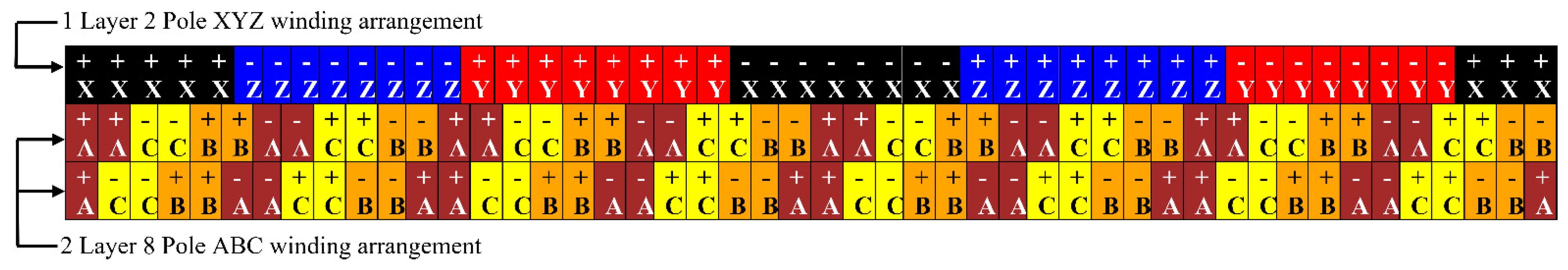
2.1. Proposed Sub-Harmonic Synchronous Machine Topology

As mentioned in the introduction section, the proposed SHSM topology is illustrated in Figure 1, and it is shown that the stator winding is driven by a single current source inverter. Furthermore, the stator winding has a unique 3-layer distributed winding configuration, where it is divided into two sets of series-connected 3-phase windings—winding ABC and winding XYZ—of which winding ABC generates an 8-pole MMF, and the winding XYZ produces a 2-pole MMF. The ABC and XYZ winding are depicted in Figure 2, in the machine layout with the proposed winding arrangement. It is important to state that the rotor of the SHSM is also comprised of two separate windings itself and they are: the field winding and the harmonic winding. While the field winding is wound in an 8-pole manner and is placed in all 8 rotor slots, the rotor harmonic winding is a 2-pole winding which is placed in only two of the rotor slots. Rotor harmonic winding is employed for inducing the sub-harmonic MMF generated by the XYZ winding of the stator. Both the rotor windings are connected with each other via a diode bridge rectifier circuit mounted on the periphery of the rotor as it can be seen in Figure 1.
Furthermore, it can be seen in Figure 2 that the 3-layer winding is placed in each slot shared by both ABC and XYZ stator windings. The 3-layer winding configuration of SHSM is such that the inner two layers are wound similar to a typical 2-layer arrangement, which is the ABC winding and has 8-poles. Whereas the third layer, outer most of the three, is coiled like a single layer winding named as XYZ winding and has 2-poles. Figure 3 shows the pole pitches of the 2 rotor windings.

2.2. Principle of Operation

The brushless operation of the SHSM is possible by utilizing sub-harmonic MMF components delivered from the stator XYZ winding to the rotor harmonic winding. The SHSM is driven by the current source inverter that delivers three phase AC currents to the stator windings. Since the stator windings are connected in series configuration, both ABC and XYZ windings are energized by the inverter with an equal amount of current. Although the stator windings are fed from a balanced 3-phase current, due to the different winding configurations, winding ABC generates 8-pole fundamental MMF component that is used for torque generation and winding XYZ generate 2 pole MMF component. In [12], the 8-pole and 4-pole components were generated in the stator winding of the machine using 2 inverters. The 8-pole was the fundamental component used for torque generation while the 4-pole considered the sub-harmonic component, was used for the rotor excitation. In the proposed SHSM topology, 8-pole ABC winding produces a fundamental rotating magnetic field and the 2-pole component is generated by using an additional 2-pole stator winding for the purpose of rotor excitation. The 2-pole and 8-pole components rotate with a different rotating speed from each other. The 3-phase balanced currents that are supplied by the inverter to the stator windings are given below,
  i A ( t ) = I 1 sin ω e t
  i B ( t ) = I 1 sin ( ω e t 2 π 3 )
  i C ( t ) = I 1 sin ( ω e t + 2 π 3 )
where,   i A ( t ) ,   i B ( t ) , and   i C ( t ) are the 3 phase supply currents, I 1 is the supplied peak current, ωe is the electrical angular frequency, and t is the time.
The rotational speed of the fundamental component and harmonic component can be calculated from Equations (4) and (5), where n s is the rotating speed of the fundamental component, f is the frequency of the supplied current, p is the number of poles of the machine, n s ( h ) is the rotating speed of the harmonic component, and h is the harmonic number, which in the proposed case is 1/4 or 0.25.
n s = 120   ×   f p
n s ( h ) =   n s h = 120   ×   f h × p
Using Equation (4) for an 8-pole machine, with 60 Hz of supplied frequency, the fundamental component of MMF will be rotating at 900 rpm. For the sub-harmonic component, putting the value of h = 0.25 in Equation (5), its rotating speed comes out to be 3600 rpm, which clearly demonstrates that the sub-harmonic component will be rotating at a different speed from the rotor speed and thus has the potential to get induced in the rotor harmonic winding. Given that, the rotor also has two sets of winding: field winding and harmonic winding. The 2-pole rotor harmonic winding induces an electromotive force (EMF) from the sub-harmonic MMF generated by the XYZ winding, and this induced EMF is then rectified through a diode rectifier circuit to a DC voltage that ultimately feeds the field winding. From that DC excitation, the 8-pole field winding creates a constant magnetic field that synchronizes with the fundamental rotating magnetic field created by the ABC winding.

3. Design and Analysis of the Proposed Machine

The design process flowchart is shown in Figure 4. As [15] is considered as the base model, to draw a valid comparison, all the design parameters of the proposed machine are the same. However, the difference lies in the stator winding arrangement and in the pole number of the harmonic windings. Once the winding was completed, electromagnetic analysis was performed to check the feasibility of the proposed brushless operation. An 8 pole, 48 slot SHSM with a 3-phase, 3-layer distributed stator winding is designed to validate the proposed topology. Based on the stator winding structure, both ABC and XYZ windings are placed throughout the 360-mechanical degree of the stator, which is illustrated in Figure 5, and each slot consists of a single-layer XYZ and a 2-layer ABC winding. For the performance comparison, the BL-WRSM of [15] has been chosen.
In [15] ABC and XYZ windings are both 2-layer windings, and they are housed separately in two equally divided slot-spaces in the stator, where winding ABC has double the number of turns than XYZ as shown in Figure 6. For the machine presented in [15], total number of slots for each phase is 16, where 8 slots are used for winding A and 8 are used for winding X, where A winding has 40 conductors per slot and X winding has 20 conductors per slot. Moreover, the number of conductors per slot is 30 when ABC and XYZ windings overlap. Therefore, average number of conductors per slot will be, (40 + 20 + 30)/3 = 30 turns per slot. As all the slots are identical in shape and size, the slot must be designed to incorporate the 40 conductors per slot, which indicates that ¾th of the slot has been utilized on average.
Now, if S1 is the Slot fill factor of ABC winding, S2 is the Slot fill factor of XYZ winding, and S3 is the slot fill factor when the slots are occupied by both ABC and XYZ windings, looking at Figure 6, the average slot fill factor, Savg, is,
S a v g = ( S 1 + S 2 + S 3 ) 3 = 3 4 S 1   [ S 2 = S 1 2 ,   S 3 = 3 4 S 1 ] = 75 %
As there were 30 conductors per slot on average in [15], it can be stated that 10 more conductors might have been incorporated but due to the topology, only 30 conductors were placed.
Now for the proposed topology, the sub-harmonic component is generated with a different technique compared to [15], with no such restrictions of different number of conductors per slot in different slots. Where, the ABC winding has 30 conductors per slot while the XYZ winding has 10 conductors per slot i.e., maximum slot utilization. As the area of slot for the proposed machine and [15] is same, for the proposed machine, unlike in [15], each slot has ABC winding as well as XYZ winding. Thus, the average slot fill factor of the proposed machine, S a v g , is,
S a v g = 3 ( S 1 ) 4 + ( S 2 ) 2 = S 1   [ S 2 = S 1 2 ] = 100 %
Therefore, it can be stated that the proposed topology improves 25% slot utilization as compared to [15], which in return results in 60% greater torque generation.
The parameters of the proposed SHSM are summarized in Table 1, and it can be seen that the rated power of the machine is considered 1281 W having a constant speed of 900 rpm. The MMF distribution of the ABC and XYZ stator windings are illustrated in Figure 7a,b for the case, where the amplitude of the phase A and X current is maximum, 6.4 A, and the value of B, C, Y and Z phases are −3.2 A. The fundamental MMF component is produced by winding ABC, and it has an 8-pole arrangement with the frequency of ωm, where ωm is the frequency in mechanical space domain. Whereas in the case of winding XYZ with its 2-pole configuration, it delivers the sub-harmonic MMF component with the frequency of (ωm)/4. Thus, the two components rotate at a different speed. In the rotor, on the other hand, the harmonic winding is placed on the rotor such that it aligns magnetically with the stator XYZ winding. Moreover, the field winding having an 8-pole arrangement aligns magnetically with winding ABC. With all that, the proposed SHSM achieves its brushless operation by inducing voltages in harmonic winding, due to the sub-harmonic MMF. These voltages then get rectified and DC current is fed to the field winding of the rotor, which magnetically locks it with the stator fundamental MMF.
It is worth pointing out that unlike the other machines [14,15] that use the sub-harmonic MMF component for the brushless operation, the proposed topology uses the maximum number of conductors per slot in the stator winding: winding ABC has 30 and XYZ has 10 numbers of turns. Although the XYZ winding contains 10 turns per slot, the stator generated MMF’s sub-harmonic component (77.5 at peak as shown in Figure 7b) is significantly higher than the fundamental MMF component (52.5 at peak as shown in Figure 7a); however, the fundamental and sub-harmonic components are sufficient to produce eloquently higher torque in the previously presented BL-WRSM in [15]. It is important to realize that the overall volume of the machine does not get bigger as compared with the BL-WRSM in [15] even though the proposed SHSM utilizes a 3-layer winding configuration. Evidently, the reason for the improved torque performance of the proposed machine is the fact that some slots were not fully utilized in the BL-WRSM in [15] while in the proposed machine all of the slots area is fully utilized for torque production and sub-harmonic generation.

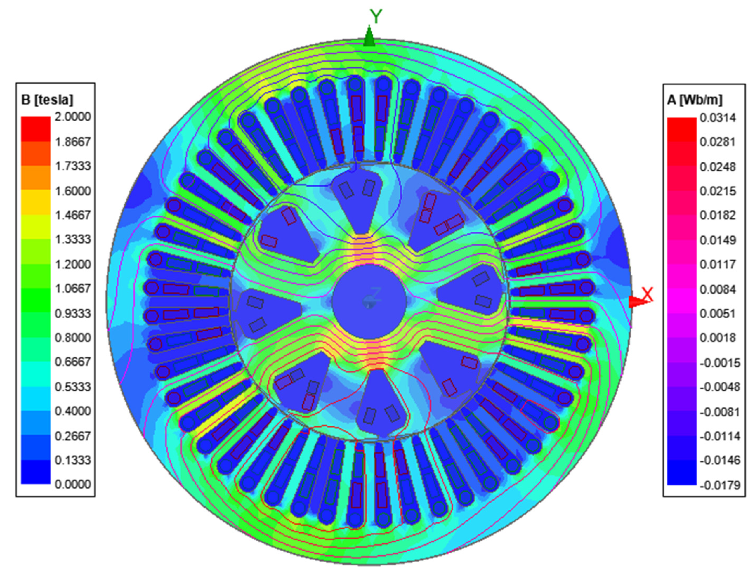
4. 2-D Finite Element Analysis

To observe the performance and feasibility, proposed SHSM has been extensively investigated utilizing a 2-D finite element method. Simulation parameters are taken from the Table 1, and the stator winding of the SHSM is supplied with a balanced 3-phase sinusoidal current with a peak current of 6.4 A at a 60 Hz frequency. The flux density and flux line distribution through the stator and the rotor of the SHSM at the rated current is illustrated in Figure 8. As it turns out, the flux density and flux lines are somewhat evenly distributed throughout the stator rotor frame for the SHSM, unlike in the case of the BL-WRSM in [15], where the distribution was found uneven because of the under-utilized stator slot space. It also shows the proposed SHSM works under the flux density of 2 T.
In Figure 9a,b, induced EMF and the current in the rotor harmonic winding by the generated MMF in the stator XYZ winding is shown, and this alternating voltage and current are having an rms value of approximately 6.11 V and 14.05 A, respectively; then, the alternating voltage and current are rectified to feed the rotor field winding. The average value of these field voltage and current are illustrated in Figure 10a,b, and they are around 1.57 V and 20.18 A, respectively. Upon observing the rectified stable field currents in the field winding, it is obvious that the brushless operation is achievable in the case of the SHSM topology. Moreover, the torque production curve of the 8-pole, 48-slot SHSM is depicted in Figure 11, where the average value is 12.53 Nm with a torque ripple of 32%.
In order to examine the effectiveness of the proposed SHSM, its performance is compared with the conventional WRSM in [14] and the single inverter BL-WRSM in [15], and the summary of the assessment is listed in Table 2. It is, however, worthy of note that for the proposed machine, all design parameters are kept the same to the BL-WRSM in [15] including outer diameters, air-gap length, stack length, the current density in the stator, and rotor winding to name a few. While all the machines are supplied with a rms current of 4.5 A, the rotor field current is found in SHSM (20.18 A) is remarkably higher than that of the BL-WRSM in [15], which is 9.8 A. The reason for the higher current is 2 pole sub-harmonic component and 3-layer stator winding arrangement. As a result of all these factors, the average torque of the SHSM is found 12.53 Nm that is approximately 60% more than the average torque production of the BL-WRSM in [15]. The proposed machine is unique compared to the machines presented in [15] considering various design parameters, and they are as follows: number of stator winding layers, pole number of the rotor’s harmonic winding, number of conductors per slot of the stator’s ABC and XYZ windings. These are listed in the Table 2.
In a nutshell, as the proposed topology utilizes maximum possible conductors in a slot compared to the BL-WRSM in [15], this results in more current induction in the rotor harmonic winding, which eventually results in greater field current on the rotor. On the other hand, with this higher field current, inevitably increases the back EMF of the machine. To keep up with the greater back EMF, the input terminal voltage has to be greater to maintain the constant supply current of 4.5 A. Therefore, it can be said that the ability of greater torque generation of the proposed topology is achieved because of higher terminal voltage which is higher only because of the greater utilization of the slot space. As a result, the input power of the proposed machine is different from the other two machines in [14,15].
Despite the performance enhancement in torque generation, the torque ripple is found to be 32%, and this issue may be covered in future research with an optimized design. Variation in performance of using different number of conductors turns per slot of XYZ winding is listed in Table 3 with fixed 30 conductor turns per slot of ABC. It can be seen from the table that 10 conductors per slot of XYZ winding shows the most promising results in all the performance indication parameters except for the torque ripple result.

5. Conclusions

Finally, it can certainly be stated that the purpose of the study to develop a brushless wound rotor synchronous machine, SHSM, is achieved. In order to validate the practicability of the SHSM, the model was substantiated with 2-D finite element method. From that, the proposed machine not only resembles the conventional BL-WRSMs, but performance-wise it surpasses in many critical aspects, and it demonstrates some certain advantages over the newly developed BL-WRSMs in [12,14,15]. The features of the SHSM are therefore listed as follows:
  • Significantly greater torque generation.
  • Utilizes maximum allowable stator slot space.
  • Single inverter brushless usage
  • No requirement of imposing complex unbalanced-cooling system.
With these advantages, the SHSM can undoubtedly be considered as a competitive alternative not only to the BL-WRSMs but also with the state-of-the-art PMSMs, especially those that are used in traction applications. One of the drawbacks of the model, torque ripple, may be reduced through optimized design, which eventually will improve the overall performance. In system applications, on the other hand, specifically in power electronic drive and control section, there is a scope for economical and uplifted performance by utilizing the three-transistor voltage source inverter topology and employing various pulsed width modulation techniques in [18,19]. Not to mention that these topics may be considered as future research concerns.

Author Contributions

Conceptualization, S.M.S.H.R. and T.A.L.; Formal analysis, S.M.S.H.R. and Q.A.; Funding acquisition, S.M.S.H.R. and Q.A.; Investigation, S.M.S.H.R. and Q.A.; Methodology, S.M.S.H.R. and T.A.L.; Software, S.M.S.H.R. and Q.A.; Supervision, T.A.L.; Writing—original draft, S.M.S.H.R.; Writing—review & editing, S.M.S.H.R., Q.A. and T.A.L. All authors have read and agreed to the published version of the manuscript.

Funding

This research received no external funding.

Conflicts of Interest

The authors declare no conflict of interest.

References

  1. Zdeněk, Č.; Pavel, M. Electric, hybrid electric and combustion engine driven cars and their impact on environment. In Proceedings of the 2011 14th European Conference on Power Electronics and Applications, Birmingham, UK, 30 August–1 September 2011; pp. 1–5. [Google Scholar]
  2. Aruna, P.; Vasan, P.V. Review on Energy Management System of Electric Vehicles. In Proceedings of the 2019 2nd International Conference on Power and Embedded Drive Control (ICPEDC), Chennai, India, 21–23 August 2019; pp. 371–374. [Google Scholar] [CrossRef]
  3. Zhu, Z.Q.; Chu, W.Q.; Guan, Y. Quantitative comparison of electromagnetic performance of electrical machines for HEVs/EVs. CES Trans. Electr. Mach. Syst. 2017, 1, 37–47. [Google Scholar] [CrossRef]
  4. Pellegrino, G.; Vagati, A.; Boazzo, B.; Guglielmi, P. Comparison of Induction and PM Synchronous Motor Drives for EV Application Including Design Examples. IEEE Trans. Ind. Appl. 2012, 48, 2322–2332. [Google Scholar] [CrossRef] [Green Version]
  5. Sarlioglu, B.; Morris, C.T.; Han, D.; Li, S. Driving Toward Accessibility: A Review of Technological Improvements for Electric Machines, Power Electronics, and Batteries for Electric and Hybrid Vehicles. IEEE Ind. Appl. Mag. 2017, 23, 14–25. [Google Scholar] [CrossRef]
  6. Pellegrino, G.; Vagati, A.; Guglielmi, P.; Boazzo, B. Performance Comparison Between Surface-Mounted and Interior PM Motor Drives for Electric Vehicle Application. IEEE Trans. Ind. Electron. 2012, 59, 803–811. [Google Scholar] [CrossRef] [Green Version]
  7. Yang, Z.; Shang, F.; Brown, I.P.; Krishnamurthy, M. Comparative Study of Interior Permanent Magnet, Induction, and Switched Reluctance Motor Drives for EV and HEV Applications. IEEE Trans. Transp. Electrif. 2015, 3, 245–254. [Google Scholar] [CrossRef]
  8. Lipo, T.A.; Du, Z.S. Synchronous motor drives-a forgotten option. In Proceedings of the 2015 Intl Aegean Conference on Electrical Machines & Power Electronics (ACEMP), 2015 Intl Conference on Optimization of Electrical & Electronic Equipment (OPTIM) & 2015 Intl Symposium on Advanced Electromechanical Motion Systems (ELECTROMOTION), Side, Turkey, 2–4 September 2015; pp. 1–5. [Google Scholar] [CrossRef]
  9. Dai, J.; Hagen, S.D.; Ludois, C.; Brown, I.P. Synchronous Generator Brushless Field Excitation and Voltage Regulation via Capacitive Coupling Through Journal Bearings. IEEE Trans. Ind. Appl. 2017, 53, 3317–3326. [Google Scholar] [CrossRef]
  10. Bilgin, B.; Liang, J.; Terzic, M.V.; Dong, J.; Rodriguez, R.; Trickett, E.; Emadi, A. Modeling and Analysis of Electric Motors: State-of-the-Art Review. IEEE Trans. Transp. Electrif. 2019, 5, 602–617. [Google Scholar] [CrossRef] [Green Version]
  11. Yao, F.; Sun, D.; Sun, L.; Lipo, T.A. Dual Third-Harmonic-Current Excitation Principle of a Brushless Synchronous Machine Based on Double Three-Phase Armature Windings. In Proceedings of the 2019 22nd International Conference on Electrical Machines and Systems (ICEMS), Harbin, China, 11–14 August 2019; pp. 1–4. [Google Scholar] [CrossRef]
  12. Ali, Q.; Lipo, T.A.; Kwon, B.-I. Design and Analysis of a Novel Brushless Wound Rotor Synchronous Machine. IEEE Trans. Magn. 2015, 51, 1–4. [Google Scholar] [CrossRef]
  13. Ali, Q.; Atiq, S.; Lipo, T.A.; Kwon, B. PM Assisted, Brushless Wound Rotor Synchronous Machine. J. Magn. 2016, 21, 399–404. [Google Scholar] [CrossRef] [Green Version]
  14. Hussain, A.; Kwon, B. A new brushless wound rotor synchronous machine using a special stator winding arrangement. Electr. Eng. 2018, 100, 1797–1804. [Google Scholar] [CrossRef]
  15. Hussain, A.; Atiq, S.; Kwon, B. Optimal Design and Experimental Verification of Wound Rotor Synchronous Machine Using Subharmonic Excitation for Brushless Operation. Energies 2018, 11, 554. [Google Scholar] [CrossRef] [Green Version]
  16. Sirewal, G.J.; Bukhari, S.S.H. Cost-Effective Scheme for a Brushless Wound Rotor Synchronous Machine. World Electr. Veh. J. 2021, 12, 194. [Google Scholar] [CrossRef]
  17. Bukhari, S.S.H.; Ali, Q.; Doval-Gandoy, J.; Ro, J.-S. High-Efficient Brushless Wound Rotor Synchronous Machine Topology Based on Sub-Harmonic Field-Excitation Technique. Energies 2021, 14, 4427. [Google Scholar] [CrossRef]
  18. Rafin, S.M.H.; Lipo, T.A.; Kwon, B. A novel topology for a voltage source inverter with reduced transistor count and utilizing naturally commutated thyristors with simple commutation. In Proceedings of the 2014 International Symposium on Power Electronics, Electrical Drives, Automation and Motion, Ischia, Italy, 18–20 June 2014; pp. 643–648. [Google Scholar] [CrossRef]
  19. Rafin, S.M.H.; Lipo, T.A.; Kwon, B. Performance analysis of the three transistor voltage source inverter using different PWM techniques. In Proceedings of the 2015 9th International Conference on Power Electronics and ECCE Asia (ICPE-ECCE Asia), Seoul, Korea, 1–5 June 2015; pp. 1428–1433. [Google Scholar] [CrossRef]
Figure 1. Machine topology for the proposed.
Wevj 13 00016 g001
Figure 2. Machine layout for the proposed SHSM.
Wevj 13 00016 g002
Figure 3. Pole pitches of the rotor 8-pole field and 2-pole harmonic windings.
Wevj 13 00016 g003
Figure 4. Flowchart of the design process.
Wevj 13 00016 g004
Figure 5. Proposed 3-layer ABC and XYZ winding configuration over 360-mechanical degrees.
Wevj 13 00016 g005
Figure 6. 2-layer ABC and XYZ winding configuration in over 360-mechanical degrees presented in [15].
Wevj 13 00016 g006
Figure 7. Stator MMF components: (a) Fundamental component; (b) Sub-harmonic component.
Wevj 13 00016 g007
Figure 8. Stator flux density and flux line plot.
Wevj 13 00016 g008
Figure 9. Induced voltage and current at the rotor harmonic winding: (a) Induced voltage; (b) Induced current.
Wevj 13 00016 g009
Figure 10. Rectified voltage and current at the rotor field winding: (a) Rectified voltage; (b) Rectified current.
Wevj 13 00016 g010
Figure 11. Torque generator of the SHSM.
Wevj 13 00016 g011
Table 1. Design parameters of the proposed SHSM.
ParameterUnitValue
Rated powerW1281
Operating speedrpm900
Stator outer diametermm177
Stator inner diametermm95
Air-gap lengthmm0.5
Shaft diametermm25
Stack lengthmm80
Number of poles of stator ABC winding-8
Number of poles of stator XYZ winding-2
Number of poles of rotor harmonic winding-2
Number of poles of rotor field winding-8
Number of stator slots-48
Conductors per stator slot in ABC winding-30
Conductors per stator slot in XYZ winding-10
Conductors per pole of harmonic winding-50
Conductors per pole of field winding-24
Table 2. Performance comparison between the conventional WRSM [14], BL-WRSM [15], and the proposed SHSM.
IndicatorUnitWRSM [14]BL-WRSM [15]Novel SHSM
Stator currentArms4.504.504.50
Filed currentAavg9.59.820.18
Harmonic currentArms05.114.05
Terminal voltageVrms68.1072.0113.89
Average torqueNm7.307.8312.53
Torque ripple%16.6718.032
Number of layers of stator winding 223
Number of poles for rotor harmonic winding -42
Number of ABC conductors/slot of stator winding 404030
Number of XYZ conductors/slot of stator winding -2010
Table 3. Variation in performance of proposed SHSM with different conductors of XYZ winding.
IndicatorUnitNumber of Conductors per Slot in XYZ Winding While Having 30 Conductors per Slot in ABC Winding
108642
Stator currentArms4.504.504.504.504.50
Field currentAavg20.1815.7410.816.091.78
Harmonic current Arms14.0511.288.275.071.81
Terminal voltageVrms113.89102.4687.6468.4850.86
Induced field voltage Vrms6.115.675.014.022.73
Rotor voltageVavg1.571.381.090.690.22
Average torqueNm12.5311.159.106.042.02
Torque ripple%3231313338
Publisher’s Note: MDPI stays neutral with regard to jurisdictional claims in published maps and institutional affiliations.

