1. Introduction
Currently, the transportation system largely relies on petroleum-derived liquid fuels (Transportation Petroleum-derived liquid fuels), and PEV as a member of new energy vehicles can help solve global environmental pollution and energy shortage [
1,
2,
3]. PEV mainly has two forms of single motor drive and multi-power source drives, and there is a distinction between distributed independent drive and centralized drive. Nowadays, compared with single motor-driven vehicles and hybrid vehicles, PEV with multiple power sources has certain advantages in multi-condition demand matching, fuel economy, energy consumption and efficiency of a power transmission system [
4]. Among them, the dual-motor coupling drive system couples the power flow of the two motors through the confluence mechanism and then to the output. Combined with reasonable control strategies, the system can operate more in the efficient area by adjusting the operating conditions of the two motors [
5].
In recent years, studying the parameter configuration of electric vehicle powertrain (or drive system) and energy management strategy has become a hot trend. However, the research reports on dual-motor coupling drive systems are relatively few in number, especially for its new dynamic coupling drive scheme design, parameter optimization matching and working mode division strategy. Ma et al. [
6] proposed a planetary gear coupling mechanism based on a dual motor structure. The research process combines the statistical analysis of the actual road and multi-working conditions and particle swarm optimization was used in parameter matching and the design of the transmission system. Li et al. [
7] proposed a dual-input coupling powertrain system (DICPS): The system set a fixed-axis gear transmission system between the power output of the two motors and the input of the planetary gear train. This study proposed a parameter matching design method by means of computational analysis. Chen et al. [
8] pointed out that the rationality of parameter design of power systems has an important influence on the dynamic performance of electric vehicles. This research conducted parameter optimization design by using simulation analysis based on Matlab and particle swarm optimization algorithm based on mixed penalty function. Hu et al. [
9] proposed a new dual-motor coupling drive system, which is equipped with three clutches, one brake and two fixed axis gear pairs in addition to a single planetary gear. In this study, the parameters of the power system were matched by calculation and analysis, and the power allocation strategies of different driving modes were analyzed and formulated by combining the efficiency characteristics of the motor.
In summary, at this stage, the related research of PEV’s ‘multi-power source-coupling mechanism’ focuses on the transmission device with a single planetary row. Moreover, most studies adopt the transmission scheme with sun gear and gear ring as input and planetary carrier as output. However, the dynamic performance of the vehicle system is different when the gear ring and the planetary carrier of the confluence mechanism are used as output, respectively, and each has its own characteristics. At the same time, if there are more parts in the power transmission system, it will reduce the efficiency of the overall system to a certain extent; on the other hand, it renders the system structure complex, which is not conducive to being lightweight and manufacturing cost reduction. In addition, the multi-power source coupling drive system often has more than one working mode. There are too many feasible schemes for the rational division of working modes (the determination of mode switching strategy) and multi-parameter matching design of PEV under full working conditions. Therefore, it is of profound research significance to design heuristically intelligent optimization algorithms to meet the needs of such engineering applications.
Therefore, this paper refers to the design idea of the confluence mechanism in a power-split CVT system and then designs a novel 3-axis dual-motor coupling drive system (N-DMCDS) based on the transmission scheme of a Simpson planetary gear mechanism. This paper takes the design requirements of a PEV as an example and carries out the motor matching selection combined with the motor data in Cruise and Carsim software. The full load speed characteristic models and efficiency characteristic models of the motor are established by the one-dimensional interpolation method and least square method, respectively, and the mean value and standard deviations of MAPE of 100 random tests’ 5-fold CV cross validation are established as evaluation indexes of modeling accuracy. By using theoretical analysis, the speed regulation characteristic model and efficiency characteristic model of N-DMCDS are obtained, and the MAP of system characteristic is plotted. Taking the power performance as the constraint condition and the mean working efficiency of the vehicle under full working conditions as the objective function, this paper proposes an optimization design method for transmission parameter matching and working mode division based on the I-SA algorithm. This paper provides valuable reference for the research of PEV’s new transmission scheme of ‘multi-power source-coupling mechanism,’ better parameter matching and the determination of working mode switching strategy.
2. Materials and Methods
2.1. A Novel 3-Axis-Simpson Dual-Motor Coupling Drive System
This paper refers to the power confluence mechanism [
10,
11,
12] commonly used in the design of hydraulic mechanical power split CVT system [
13,
14]. The design idea of this type of confluence mechanism is similar to that of the Simpson type planetary gear device. Two planetary rows (P
1 and P
2) are adopted, and two sun gears of double rows, planetary carrier of P
1 and gear ring of P
2 are bunded.
The design scheme of a novel dual-motor coupling drive system presented in this paper is shown in
Figure 1.
In addition to two planetary rows, the novel system consists of three pairs of fixed axis gear pairs i1, i2 and i3 (among them, i1 adopts the way of setting external gear in P2 gear ring to further realize lightweight), two clutches C1 and C2 and three transmission shafts. The novel system has two working modes. As PEV is running, the output power of motor 1 and motor 2 is transmitted to the sun gear of P1 (or P2) and the planetary carrier of P1 (or gear ring of P2), respectively. When the clutch C1 is combined, the coupled power is exported from the gear ring of P1 and then through the i2 gear pair to the output shaft (Mode 1). In a similar manner, when the clutch C2 is combined, the coupled power is exported from the planetary carrier of P2 and then through the i3 gear pair to the output shaft (Mode 2). Therefore, the change of working mode can be easily realized by switching clutch C1 and C2.
According to the calculation relationship (, and are the output speed of sun gear, gear ring and planetary carrier, respectively; and is the characteristic parameter of planetary rows) of the rotational speed of confluence mechanism and the calculation relationship of the torque (, and are the output torque of sun gear, gear ring and planetary carrier, respectively), the characteristics of the new system can be derived. The speed regulation characteristics and torque characteristics of the novel system are shown below:
- (1)
- (2)
Mode 2:
in which
is the speed of output shaft for dual-motor coupling drive system;
and
are the output speeds of motor 1 and motor 2, respectively;
and
are output torques of motor 1 and motor 2;
is the running resistance of PEV;
is the rolling radius of tire; and
is the total efficiency of PEV powertrain system.
2.2. Design Demand Calculation of PEV
In this paper, the transmission efficiency
between planetary carrier and gear ring is set to 0.98 in the conceptual design stage, the transmission efficiency
between planetary carrier and sun gear is set to 0.97 and the transmission efficiency
between sun gear and gear ring is set to 0.96. In this paper, the power transfer routes of PEV are divided into two according to motor 1 and motor 2. According to the power proportion of each transmission route and the transmission efficiency of each component, the total transmission efficiency of the PEV is estimated. Then, the vehicle efficiency characteristics of PEV equipped with N-DMCDS are calculated as follows:
in which
and
are the efficiencies of N-DMCDS under mode 1 and mode 2, respectively;
and
are the working efficiencies of motor 1 and motor 2, respectively; and
is the proportion of motor 2′s output power to total input power.
The PEV parameters used in this paper are shown in
Table 1.
In general, the vehicle is mainly affected by rolling resistance and air resistance when driven at a constant speed on a horizontal road. This paper calculates the PEV’s demand power
based on maximum speed:
in which
is the power required to overcome driving resistance;
is the acceleration of gravity; and
is coefficient of rolling resistance.
In this paper, the total transmission efficiency of the vehicle system is set to 0.8 in the conceptual design stage, and then the expected demand power is increased by 1~3 kW to ensure the dynamic performance of the vehicle. Finally, the output power of this PEV’s power source should be 43 kW through calculation.
2.3. Data Acquisition of Motor Characteristics and Model Establishment
According to the power calculation results of PEV’s power source in
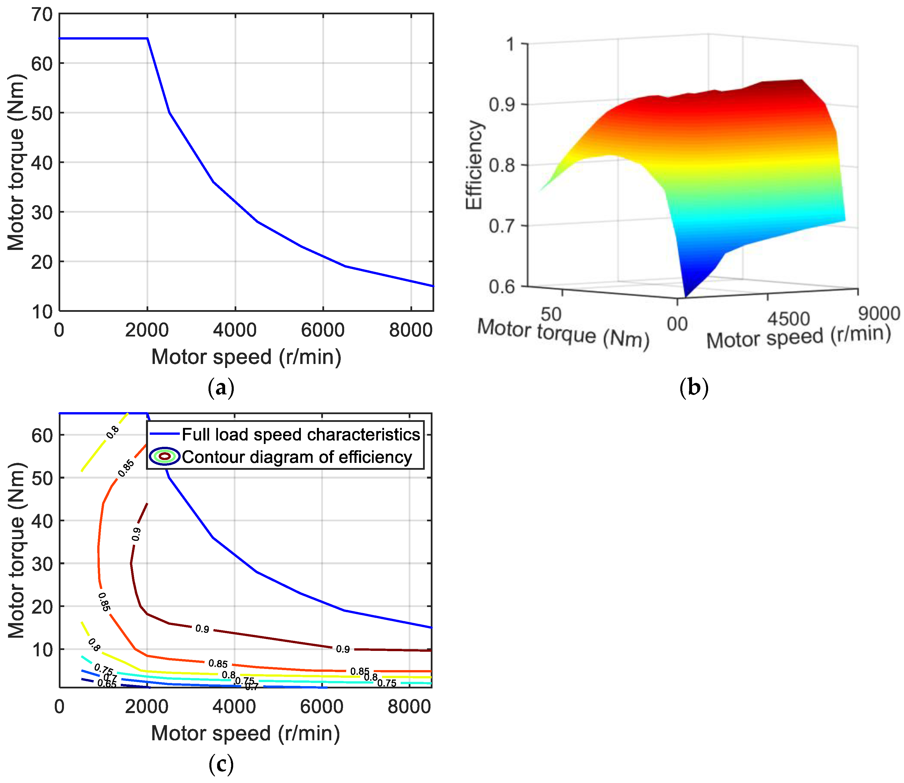
Section 2.2 and combined with the demand of torque characteristics of motor 1 and motor 2 (the power of motor 1 is transmitted to the sun gear, so the output torque is relatively small; the power of motor 2 is transmitted to the gear ring or planetary carrier, so the output torque is relatively large), this paper selects a 13 kW motor and 30 kW motor for motor 1 and motor 2, respectively. Among them, data of 13 kW motor come from Cruise software, and the data of 30 kW motor come from Carsim software.
The full load speed characteristics and efficiency characteristics of motor 1 (13 kW) and motor 2 (30 kW) are shown in
Figure 2 and
Figure 3, respectively.
This paper uses a one-dimensional linear interpolation method to establish the full load speed characteristics models of two motors. Polynomial regression models of efficiency characteristics of two motors are established by the least square method. In order to verify the accuracy of the motor efficiency characteristic model, this paper uses the mean value of
MAPE (mean absolute percentage error) of 100 random tests’ 5-fold CV cross validation as evaluation indexes of modeling accuracy. The calculation formula of
MAPE is as follows:
in which
is an estimated value based on motor efficiency model;
is the actual value of motor efficiency; and
is total data of training set or test data.
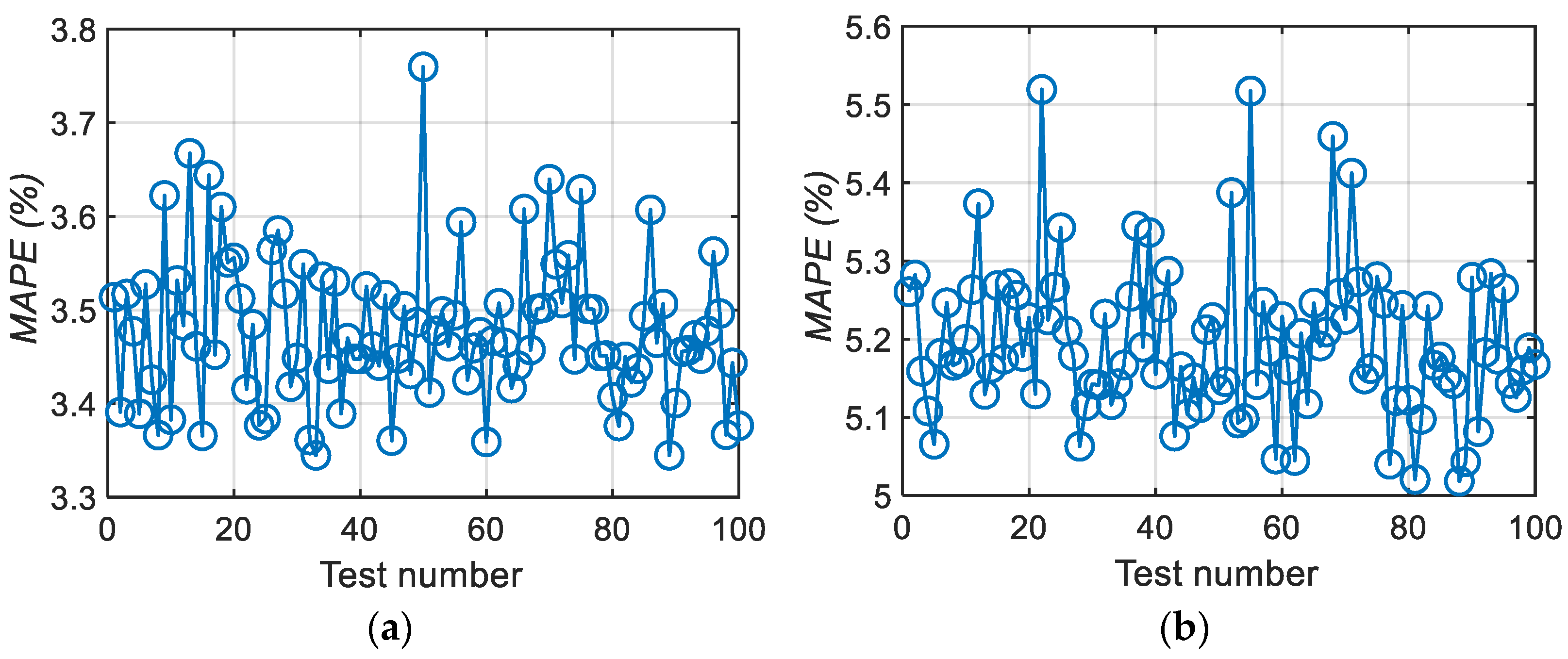
The mean values of 100 random tests’
MAPE are 3.478% (motor 1) and 5.195% (motor 2), the standard deviations are 0.078% (motor 1) and 0.097% (motor 2) and the values of
MAPE for a single test are shown in
Figure 4.
Therefore, the motor efficiency characteristic model used in this paper has sufficient accuracy, and the polynomial regression expression is as follows:
in which
is the motor efficiency model based on polynomial regression; and
~
are the coefficients of polynomials.
2.4. Method of Parameter Matching and Mode Switching Strategy Based on I-SA
The N-DMCDS proposed in this paper has two working modes; in particular, PEV has two working modes. The speed regulation characteristics of these two working modes have overlapping areas. Moreover, in the overlapping area, the efficiency of the two working modes is different when the PEV is in the same working condition. Therefore, it is necessary to study and make decisions on the selection of working modes in the overlapping areas. In addition, different transmission parameters for N-DMCDS will change the dynamic performance of PEV, and the change will result in the change of selecting PEV’s (equipped with N-DMCDS) working mode and the working strategy of two motors, thus affecting the economic performance of the vehicle. In summary, there is also a mutual coupling relationship between the parameter matching of N-DMCDS and the determination of the mode switching strategy. This paper proposes an I-SA algorithm for parameter matching and mode division of N-DMCS.
The I-SA algorithm used in this paper refers to the algorithm flow that has been proposed and verified in previous studies [
15,
16]. The research method proposed in this paper refers to the idea of the penalty function method and takes the achievement statuses of PEV dynamic performance requirements as mandatory constraints. If the maximum speed of PEV after optimization design is less than 130 km/h, and the output power cannot achieve the full coverage of 0~43 kW, it is judged as a failure of optimization design. At this time, the algorithm outputs the maximum value of an objective function. This paper uses the average efficiency of PEV under all working conditions as the objective function of I-SA algorithm. The objective function
is as follows:
in which
and
are the number of discrete points for PEV’s power in 0~43 kW and in the entire speed range; and
is the vehicle efficiency of PEV at the
ith power point and
jth speed point.
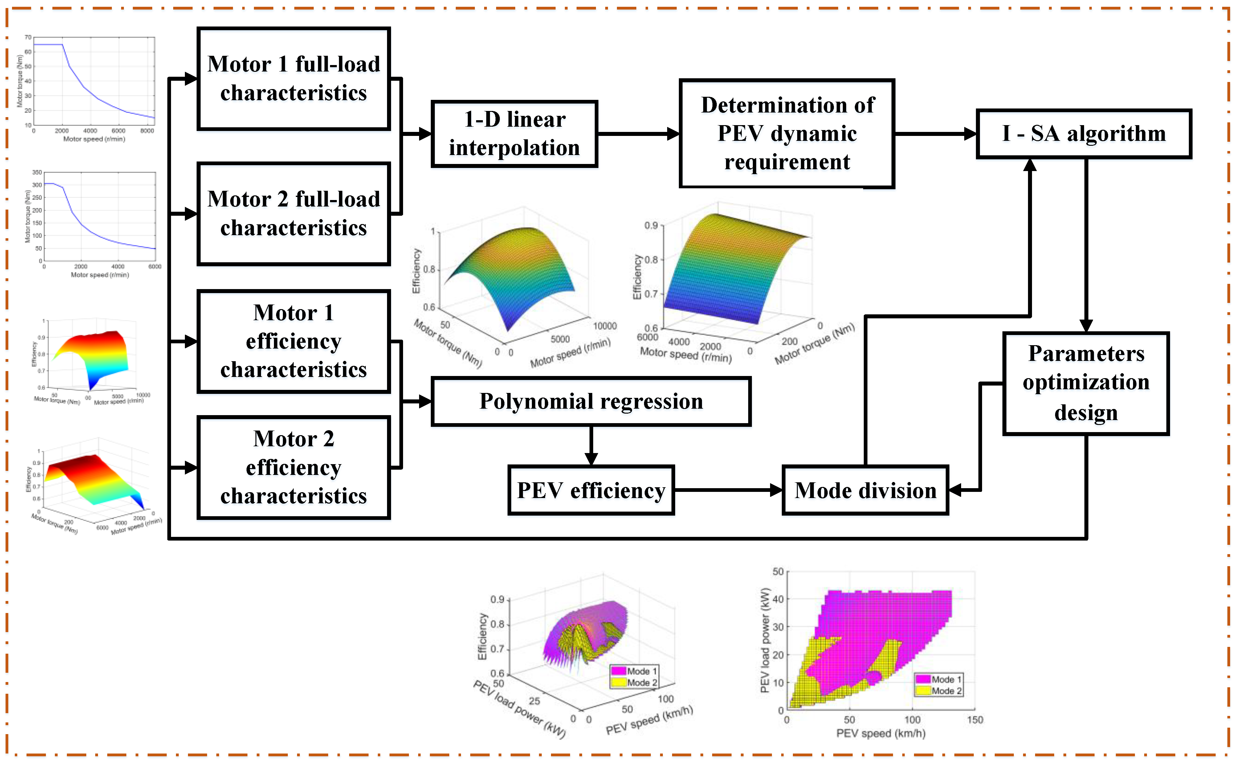
The technical route of ‘the method of parameter matching and mode division based on I-SA algorithm’ is shown in
Figure 5.
3. Results
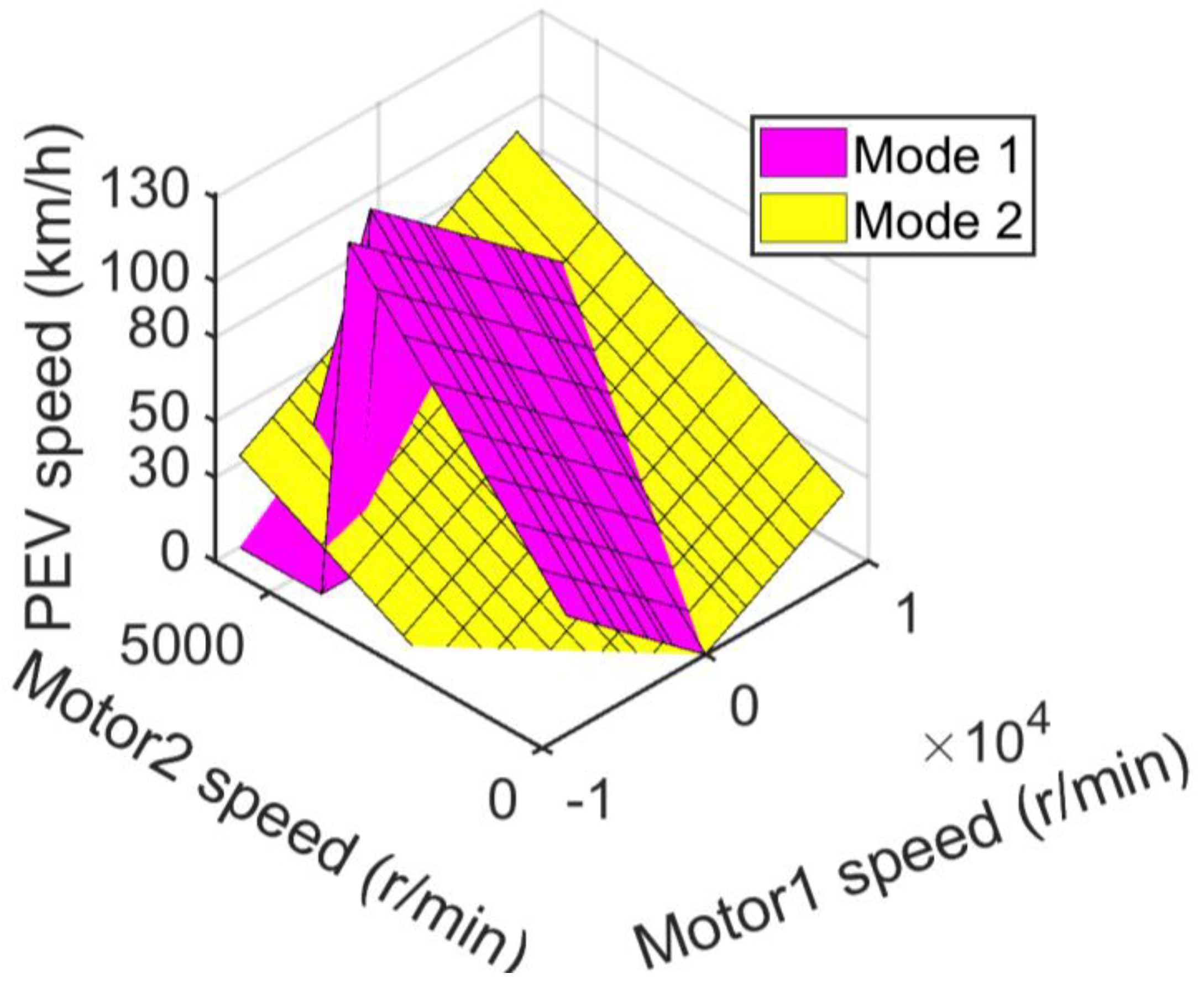
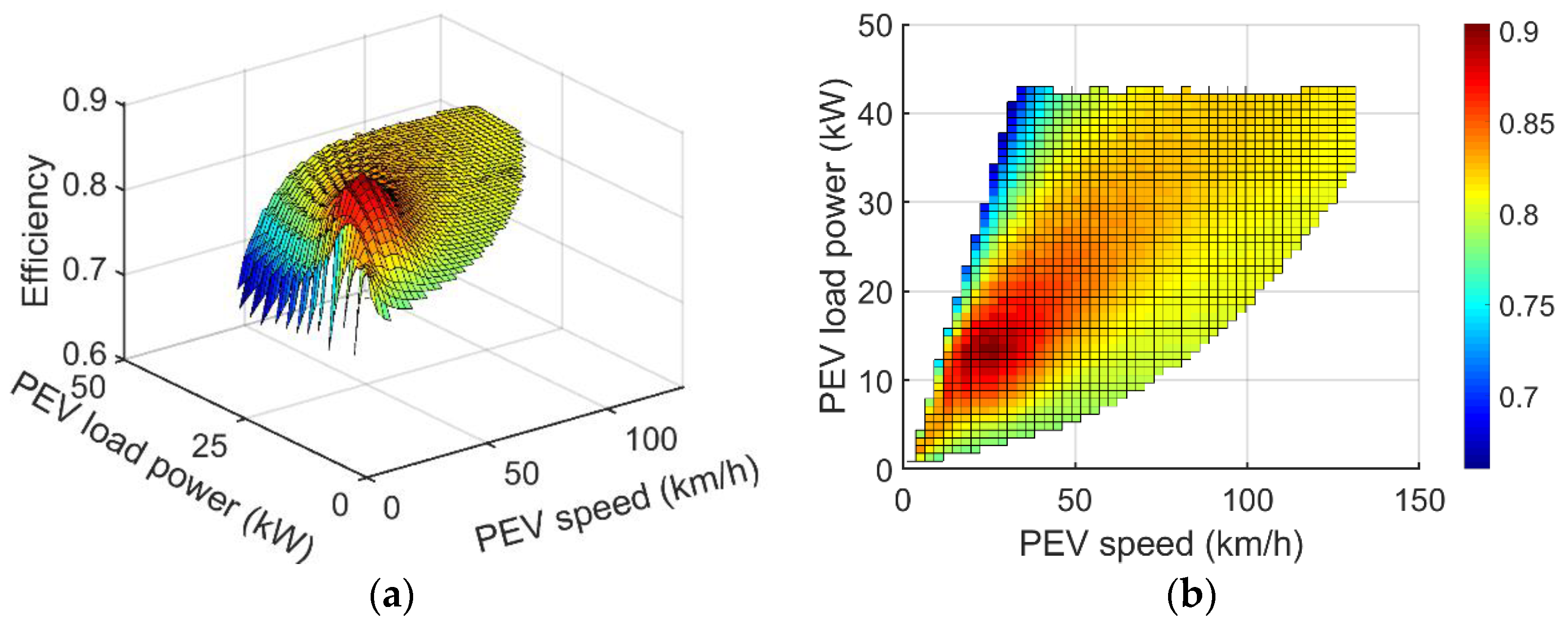
The speed regulation and efficiency characteristics of PEV are shown in
Figure 6,
Figure 7 and
Figure 8 when N-DMCDS matches the original design parameters.
According to
Figure 6,
Figure 7 and
Figure 8, the maximum speed of PEV is 131.51 km/h under the original design parameters, of which the maximum speed is 131.51 km/h under mode 1 and 92.06 km/h under mode 2. When PEV is in mode 1, it can fully utilize full power of the dual motor (0~43 kW), the utilization rate of power is 100%, the maximum efficiency is 90.37% and the average efficiency of all working conditions is 81.45%. When the PEV is in mode 2, the power range of the dual motor can be used as 0~26.33 kW, the utilization rate of power is 61.23%, the maximum efficiency is 91.34% and the mean efficiency of all working conditions is 82.43%.
After the optimization of ‘the method of parameter matching and mode division based on I-SA algorithm’ proposed in this paper, the iterative evolution curve of the I-SA algorithm is shown in
Figure 9. The optimized parameters are shown in
Table 2. The vehicle characteristics of the optimized PEV are shown in
Figure 10.
As shown in
Figure 9, the application of the I-SA algorithm can effectively complete the optimization design of N-DMCDS without premature phenomenon, and the algorithm always maintains the iterative evolution state during operation. As shown in
Figure 10, after optimization, the maximum speed of PEV is 142.56 km/h, the power utilization rate of double motors is 100% (the optimized N-DMCDS can provide full play to the full power of dual motors), the maximum efficiency is 91.19% and the average efficiency under all working conditions is 83.91%. Comparisons of maximum speed and efficiency characteristics of PEV before and after optimization and comparisons of the characteristics of mode 1 and mode 2 are shown in
Table 3.
According to
Table 3, before and after optimization, the dual-motor power utilization rate of PEV is always 100%. However, the maximum speed increased by 8.4024% and the mean efficiency increased by 2.6799% under all working conditions. Before optimization, the mean efficiency of mode 1 is lower than that of mode 2. The mean efficiency of mode 1 is higher than that of mode 2 after optimization. This is because PEV uses mode 1 more when driving. Therefore, the method proposed in this paper adaptively prioritizes the efficiency characteristics of mode 1 in optimization design. This also makes the mean efficiency and maximum efficiency of mode 2 slightly lower than that before optimization.
In order to further compare the efficiency characteristics of the single motor drive system and the dual-motor coupling drive system, this paper assumes that the single motor drive system consists of a motor and a two-stage gear reducer. Then, the average efficiencies of 13 kW and 30 kW motors under all working conditions are 80.94% and 77.66%, respectively. Therefore, the average efficiency of N-DMCDS proposed in this paper is better than that of a single motor working system under all working conditions.
Mode 1 corresponds to a single planetary gear with gear ring as the output system, while mode 2 corresponds to a single planetary gear with a planetary carrier as the output system. According to the results of this study, for the dual-motor coupled drive system, the working mode with planetary carrier as the output is more suitable for the working conditions of medium and low speeds. The working mode with gear ring as the output has ideal characteristics in the entire vehicle speed range.
4. Conclusions
This paper designs a novel 3-axis dual-motor coupling drive system (N-DMCDS) based on the transmission scheme of the Simpson planetary gear mechanism. Under the value of the original parameter design, the PEV equipped with the system has the highest driving speed of 131.51 km/h, the power utilization rate of the dual motor is 100% and the mean efficiency of all working conditions is 81.72%. The proposed optimization design method in this paper based on I-SA has good effectiveness and fast convergence. After optimization, while the power utilization rate of the two motors is unchanged, the maximum speed of PEV increased by 8.4024% and the mean efficiency is increased by 2.6799% under all working conditions. According to research results of this paper, compared with the two working modes, the dual-motor coupling drive system with the gear ring as the output has relatively better utilization rates of dual-motor power and has a relatively wider speed range under the premise of ensuring power performance. Moreover, the dual-motor coupling drive system with planetary carrier as output has more ideal working characteristics at low and medium speeds.


