
An Anti-Interference Control Method for an AGV-WPT System Based on UIO-SMC


Abstract
:1. Introduction
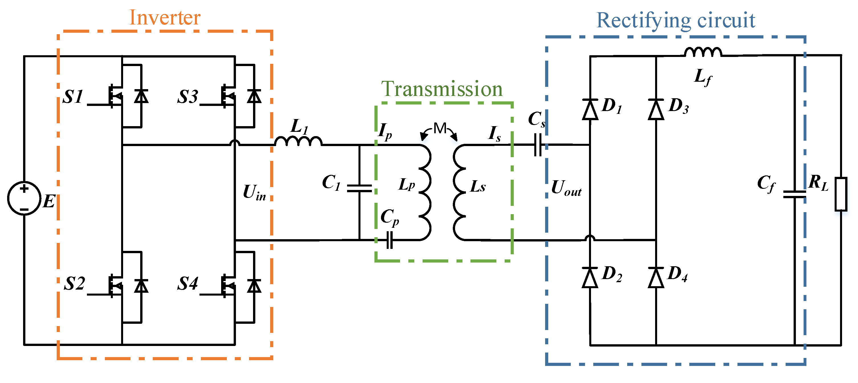
2. System Topology
3. Control System Design
3.1. Sliding Mode Controller Design
3.2. Unknown Input Observer Design
4. Verification and Discussion
4.1. System Structure Design
4.2. Analysis of Simulation Result
4.2.1. Controller Performance
4.2.2. Observer Performance
4.3. Analysis of Experimental Results
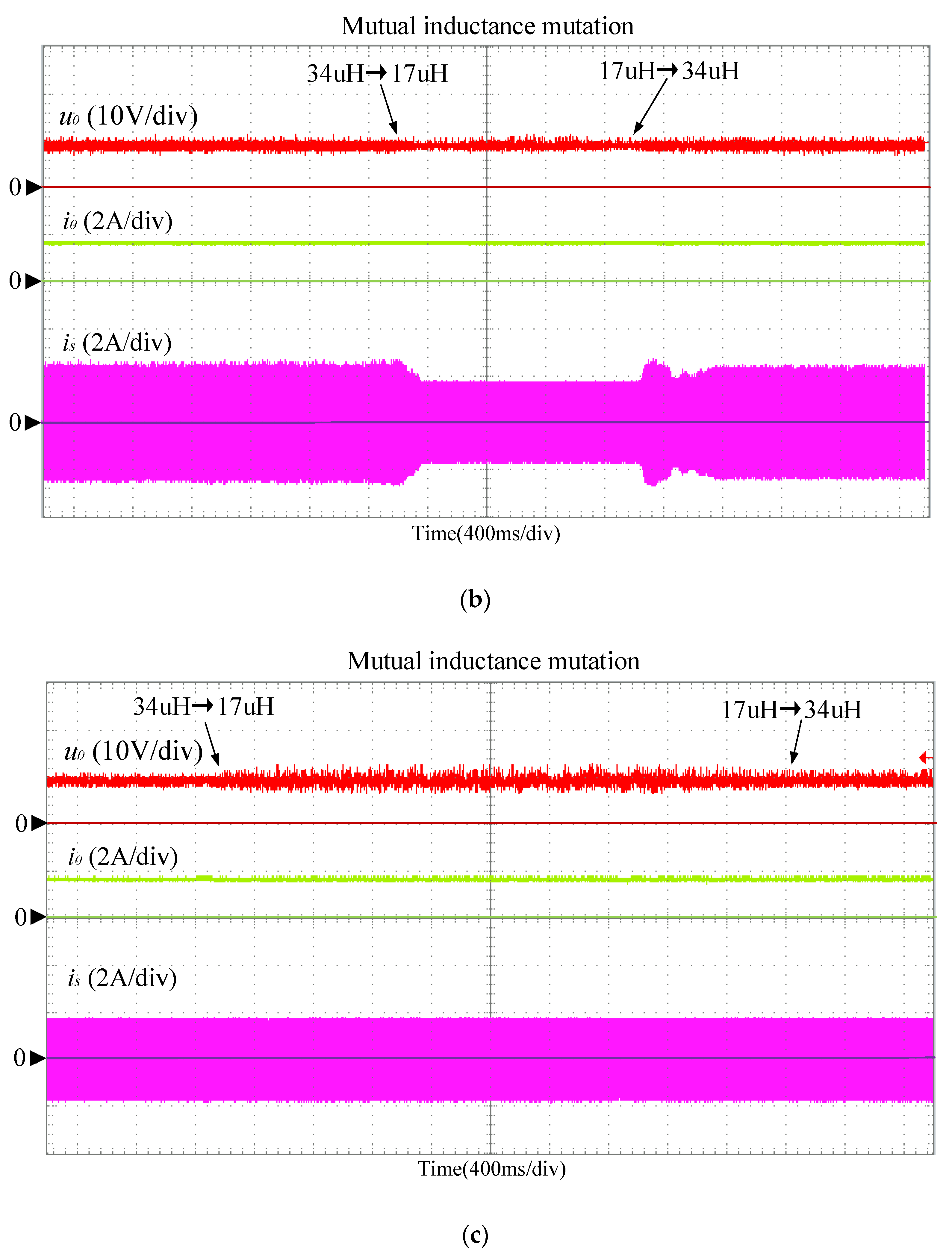
4.3.1. Coil Offset Experiments
4.3.2. Load Mutation Experiments
5. Conclusions
Author Contributions
Funding
Institutional Review Board Statement
Informed Consent Statement
Data Availability Statement
Conflicts of Interest
References
- Patil, D.; Mcdonough, M.K.; Miller, J.M.; Fahimi, B.; Balsara, P.T. Wireless Power Transfer for Vehicular Applications: Overview and Challenges. IEEE Trans. Transp. Electrif. 2018, 4, 3–37. [Google Scholar] [CrossRef]
- Watrin, N.; Blunier, B.; Miraoui, A. Review of adaptive systems for lithium batteries State-of-Charge and State-of-Health estimation. In Proceedings of the 2012 IEEE Transportation Electrification Conference and Expo (ITEC), Dearborn, MI, USA, 18–20 June 2012; pp. 1–6. [Google Scholar]
- Locorotondo, E.; Corti, F.; Pugi, L.; Berzi, L.; Reatti, A.; Lutzemberger, G. Design of a Wireless Charging System for Online Battery Spectroscopy. Energies 2021, 14, 218. [Google Scholar] [CrossRef]
- Corti, F.; Reatti, A.; Nepote, A.; Pugi, L.; Pierini, M.; Paolucci, L.; Grasso, F.; Grasso, E.; Nienhause, M. A Secondary-Side Controlled Electric Vehicle Wireless Charger. Energies 2020, 13, 6527. [Google Scholar] [CrossRef]
- Shi, L.; Alou, P.; Oliver, J.; Rodriguez, J.C.; Delgado, A.; Cobos, J.A. A self-adaptive wireless power transfer system to cancel the reactance. IEEE Trans. Ind. Electron. 2020, 28, 3044817. [Google Scholar] [CrossRef]
- Naghash, R.; Alavi, S.M.M.; Afjei, S.E. Robust Control of Wireless Power Transfer Despite Load and Data Communications Uncertainties. IEEE Trans. Emerg. Sel. Top. Power Electron. 2020, 9, 4897–4905. [Google Scholar] [CrossRef]
- Yang, Y.; Zhong, W.; Kiratipongvoot, S.; Tan, S.; Hui, S.Y.R. Dynamic Improvement of Series–Series Compensated Wireless Power Transfer Systems Using Discrete Sliding Mode Control. IEEE Trans. Power Electron. 2018, 33, 6351–6360. [Google Scholar] [CrossRef]
- Smagulova, A.; Lu, M.; Darabi, A.; Bagheri, M. Simulation Analysis of PI and Fuzzy Controller for Dynamic Wireless Charging of Electric Vehicle. In Proceedings of the 2020 IEEE International Conference on Environment and Electrical Engineering and 2020 IEEE Industrial and Commercial Power Systems Europe (EEEIC/I&CPS Europe), Madrid, Spain, 9–12 June 2020; pp. 1–6. [Google Scholar] [CrossRef]
- Yuan, L.; Wang, J.; Chen, G.; Zhang, Z.; Tang, C. Tracking method of optimal efficiency point of wpt system based on fuzzy control. Guangdong Electr. Power 2018, 31, 52–58. [Google Scholar]
- Sohn, Y.H.; Choi, B.H.; Lee, E.S.; Lim, G.C.; Cho, G.H.; Rim, C.T. General Unified Analyses of Two-Capacitor Inductive Power Transfer Systems: Equivalence of Current-Source SS and SP Compensations. IEEE T. Transp. Electr. 2015, 30, 6030–6045. [Google Scholar] [CrossRef]
- Li, S.; Yang, J.; Wu, B.; Li, Q.; Wang, J. Finite-time disturbance observer based non-singular terminal sliding mode control for pulse width modulation based DC-DC buck converters with mismatched load disturbances. IET Power Electron. 2016, 9, 1995–2002. [Google Scholar]
- Zheng, C.M.; Zhang, J.S.; Chen, R. Discrete-time sliding mode control based on improved disturbance compensation reaching law. Control. Decis. 2019, 34, 880–884. [Google Scholar]
- Wang, S.; Yu, H.; Gao, X.; Liu, X. ESO-Based Adaptive Sliding Control for Nonlinear Servo System with Unknown Disturbance and Uncertainties. In Proceedings of the 2018 10th International Conference on Modelling, Identification and Control (ICMIC), Guiyang, China, 2–4 July 2018; pp. 1–5. [Google Scholar]
- Maqsood, H.; Qu, Y. Nonlinear Disturbance Observer Based Sliding Mode Control of Quadrotor Helicopter. J. Electr. Eng. Technol. 2020, 15, 1453–1461. [Google Scholar] [CrossRef]
- Rong, J.; Yang, H.; Wang, J.; Yu, L. Design and implementation of GPI observer based sliding mode control for DC-DC buck converter. In Proceedings of the 2019 Chinese Automation Congress (CAC), Hangzhou, China, 22–24 November 2019; pp. 4256–4261. [Google Scholar] [CrossRef]
- Jaafar, A.; Godoy, E.; Lefranc, P.; Shi, X.L.; Fayaz, A.; Nan, L. Nonlinear Sliding Mode Observer and Control of High Order DC-DC Converters. In Proceedings of the IECON 2010—36th Annual Conference on IEEE Industrial Electronics Society, Glendale, AZ, USA, 7–10 November 2010; pp. 180–186. [Google Scholar] [CrossRef]
- Wang, S.; Na, J.; Ren, X.; Yu, H.; Yu, J. Unknown input observer-based robust adaptive funnel motion control for nonlinear servomechanisms. Int. J. Robust Nonlinear Control. 2018, 18, 6163–6179. [Google Scholar] [CrossRef]
- Chwei-Sen, W.; Covic, G.A.; Stielau, O.H. Investigating an LCL load resonant inverter for inductive power transfer applications. IEEE Trans. Transp. Electrif. 2004, 19, 995–1002. [Google Scholar]
- Pantic, Z.; Bai, S.; Lukic, S.M. ZCS LCC-Compensated resonant inverter for inductive-power-transfer application. IEEE Trans. Ind. Electron. 2011, 58, 3500–3510. [Google Scholar] [CrossRef]
- Corti, F.; Paolucci, L.; Reatti, A.; Grasso, F.; Pugi, L.; Tesi, N.; Grasso, E.; Nienhaus, M. A Comprehensive Comparison of Resonant Topologies for Magnetic Wireless Power Transfer. In Proceedings of the 2020 IEEE 20th Mediterranean Electrotechnical Conference (MELECON), Palermo, Italy, 16–18 June 2020; pp. 582–587. [Google Scholar] [CrossRef]
- Cai, H.; Shi, L.; Li, Y. Output Power Adjustment in Inductively Coupled Power Transfer System. Trans. China Electrotec. Soc. 2014, 29, 215–220. [Google Scholar]
- Tarbouriech, S.; Turner, M. Anti-windup design: An overview of some recent advances and open problems. IET Control. Theory Appl. 2009, 3, 1−19. [Google Scholar] [CrossRef] [Green Version]
- Na, J.; Chen, A.S.; Herrmann, G. Vehicle Engine Torque Estimation via Unknown Input Observer and Adaptive Parameter Estimation. IEEE Trans. Veh. Technol. 2018, 67, 409–422. [Google Scholar] [CrossRef] [Green Version]
- Zhong, B.; Tang, L. Design and Simulation on PID Variable Damping Ratio Controller of Second-Order System. In Proceedings of the 2010 2nd International Conference on Information Engineering and Computer Science, Wuhan, China, 25–26 December 2010; pp. 1–4. [Google Scholar] [CrossRef]
- Liu, J.; Xiao, F.; Ma, W.; Fan, X.; Chen, W. PWM-Based sliding mode controller for three-levelfull-bridge DC-DC converter that eliminates static output voltage error. J. Power Electron. 2015, 15, 378–388. [Google Scholar] [CrossRef] [Green Version]
- Zhou, S. Design and study on a precision LCR measurement system. J. Electron. Meas. Instrum. 2003, 3, 1–5. [Google Scholar]


| Observer Type | ESO13 | SMO16 | UIO17 | Observer in this Paper |
|---|---|---|---|---|
| Number of parameters to be adjusted | 3 | 2 | 1 | 1 |
| Whether to add wave filter | No | No | Yes | Yes |
| Other features | Designed ESO can reduce control gain of SMC | Stability of SMC + SMO is proven; chattering caused by constant velocity approaching law in SMO is inevitable | Proposed and used in servo mechanism | Initial observation error is small; mutual inductance disturbance observed in WPT system, which can suppress controller chattering |
| Description/Unit | Parameter | Value |
|---|---|---|
| Inverter input DC voltage (V) | E | 18 |
| Inverter frequency (kHz) | f | 85 |
| Primary side topological inductance (μH) | L1 | 31 |
| Primary side coil inductance (μH) | Lp | 79 |
| Primary sideline compensation capacitor (nF) | Cp | 33 |
| Primary topology resonance capacitance (nF) | C1 | 47 |
| Secondary side coil inductance (μH) | Ls | 70 |
| secondary side resonant capacitance (nF) | Cs | 56 |
| Filter inductance (μH) | Lf | 100 |
| Filter capacitor (μF) | Cf | 470 |
| Control Parameter | Value |
|---|---|
| λ | 0.001 |
| σ | 0.99 |
| α | 6.6 × 10⁶ |
| β | 3 × 10¹³ |
| η | 1 |
| kp | 1.2 |
| ki | 180 |
Publisher’s Note: MDPI stays neutral with regard to jurisdictional claims in published maps and institutional affiliations. |
© 2021 by the authors. Licensee MDPI, Basel, Switzerland. This article is an open access article distributed under the terms and conditions of the Creative Commons Attribution (CC BY) license (https://creativecommons.org/licenses/by/4.0/).
Share and Cite
Hou, J.; Huang, W.; Huang, D. An Anti-Interference Control Method for an AGV-WPT System Based on UIO-SMC. World Electr. Veh. J. 2021, 12, 220. https://doi.org/10.3390/wevj12040220
Hou J, Huang W, Huang D. An Anti-Interference Control Method for an AGV-WPT System Based on UIO-SMC. World Electric Vehicle Journal. 2021; 12(4):220. https://doi.org/10.3390/wevj12040220
Chicago/Turabian StyleHou, Jun, Weidong Huang, and Dongxiao Huang. 2021. "An Anti-Interference Control Method for an AGV-WPT System Based on UIO-SMC" World Electric Vehicle Journal 12, no. 4: 220. https://doi.org/10.3390/wevj12040220