Article

Shear Property and Uniform Vertical Load Capacity of Bamboo I-Beams

1
Pan Tianshou College of Architecture, Art and Design, Ningbo University, Ningbo 315211, China
2
Research Institute of Wood Industry of Chinese Academy of Forestry, Beijing 100091, China
*
Author to whom correspondence should be addressed.
Forests 2022, 13(6), 826; https://doi.org/10.3390/f13060826
Submission received: 5 May 2022 / Revised: 21 May 2022 / Accepted: 24 May 2022 / Published: 25 May 2022
(This article belongs to the Special Issue Physical Properties of Wood)

Abstract

:
Bamboo oriented strand boards (BOSB) are very suitable for application in construction structures because of their excellent mechanical properties. This research investigated the shear performance of bamboo I-beams composed of BOSB to verify the structural performance of I-beams. Short beam shear tests and uniform vertical load capacity tests were performed to investigate the effects of various factors on the properties of bamboo I-beams. The results showed that shear bearing capacity and uniform vertical load capacity of bamboo I-beams exceeded the requirements for performance-rated I-Joists in APA PRI-400-2021. The shear bearing capacity, stiffness, and failure types of bamboo I-beams were determined by the web materials, flange–web joint type, and beam depth. Increasing the bamboo I-beam depth without changing the flange dimensions had no significant effect on the shear bearing capacity and stiffness of bamboo I-beams. The shear bearing capacity and stiffness of wooden orientated strand board webbed I-beams were almost half of those of bamboo I-beams with the same depth. The shear bearing capacities of specimens calculated based on the shear bearing capacity calculation formula of I-beams recommended in the Canadian standard were reasonably close to the experimental results. The uniform vertical load capacity of bamboo I-beams gradually decreased as the depth of the bamboo I-beam increased from 300 mm to 500 mm.

1. Introduction

Bamboo is abundantly available in many countries, and it is a very promising substitution material for wood due to its rapid growth rate, short rotation age, high tensile strength, and traditional usage as a building material [1]. The design and use of structural bamboo products allows more efficient use of this renewable resource. Above all, the BOSB process represents one of the best opportunities for automation, property control and consistency, mass production, and resin efficiency in the manufacture of bamboo-based building materials, with minimal waste [2]. The density, modulus of rupture (MOR), and modulus of elasticity (MOE) parallel to the surface strand direction are 0.7–0.85 g·cm−3, 70–85 MPa, and 8–11 GPa, respectively [3,4]. The density and MOR are higher than those of Douglas fir and Southern Pine, but the MOE is equivalent to that of Douglas fir and Southern Pine at the 24F-E4 level of standard ANSI/AITC 117-2010 [5]. With such favorable mechanical characteristics and renewable characteristics, bamboo orientated strand boards are competitive with commonly used wooden building materials [6]. Compared with the commonly used wooden building materials, BOSBs have higher strength and almost the same elastic modulus, but their density is higher than that of wooden building materials.
In wooden constructions, the beam is the main load-bearing member, and its performance greatly affects the safety of the whole structure. However, due to the relatively high density of BOSB, it is necessary to prepare a bamboo sectional beam with high strength and less material through a reasonable cross-sectional design. Through research, I-beams have become able to bear the same load as solid wooden beams at the cost of considerably less materials, and they have low performance variability and good dimensional stability [7,8]. Moreover, previous research has found that the constituent materials, joints, and geometry influence the short- and long-term performances of wooden I-beams [9,10,11,12,13]. In recent years, the design and manufacturing technology of I-beams composed of bamboo-based composites were reported [14]. For instance, the fabrication of I-beams with glue-laminated bamboo in flanges and plywood or OSB in webs [15,16] and bamboo I-beams composed of bamboo plywood flange and web were investigated [17]. The creep behavior of bamboo beams [18] and reinforcement of glued laminated bamboo [19] were also studied. It was believed that both the flexure and shear resistances of I-beams composed of bamboo-based composites qualify for structural purposes [20,21]. The critical properties of I-beams for residential construction are the bending strength and stiffness. In research on laminated bamboo–timber I-beams, the flexural stiffness of the bamboo–timber beams increased as the number of layers of bamboo scrimber increased. It was found that the bearing capacity and stiffness of bamboo–timber beams increased compared with the control timber beams [22]. However, the manufacture of bamboo I-beams composed of bamboo strand board has seldom been reported, despite the high structural strength of BOSB.
For non-residential construction, such as commercial and industrial buildings, other properties, such as the shear and uniform vertical load capacity, are also probable main quality parameters of I-beams in virtue of their higher loading [23]. As a natural composite material, bamboo also has low tensile and shear strength and brittle behavior under tension and shear. In addition, short shear testing is one of the important quality detection tests of I-beams. In this paper, short shear testing of I-beams composed of BOSB was proposed. The influences of various factors, including web type, types of web to flange joints, and beam depth, on the shear capacity and uniform vertical load capacity of I-beams were explored and the shear bearing capacity of I-beams was predicted. The study provides a theoretical basis for the design and application of construction components fabricated from BOSB.

2. Materials and Methods

2.1. Materials

The bamboo for this study was derived from four-to-six-year-old bamboo (Dendrocalamus giganteus Munro) collected from Mangshi, Yunnan, China. The strands’ dimensions were 150 mm long, 0.8 mm thick, and 5–60 mm wide, and the moisture content of the strands was 5%. Emulsion polymer isocyanate adhesive (Yonglifa Industry Co., Ltd., Yunnan, China) was used as an adhesive for bonding strands together according to a mass fraction of 6% based on the oven-dried strand mass. Bamboo orientated strand boards were prepared at beltline scale with a hydraulic hot press according to the dimensions of 2440 mm × 1220 mm × t mm and the target density of 0.9 g·cm−3. The board was hot-pressed under a pressure of 3–4 MPa at 160–165 °C for 1.25 min·mm−1. The boards differed in the strand orientation distribution and were produced by Yunnan Yonglifa Industry Co., Ltd. Two distinctive orientation types were considered—bamboo fibers primarily oriented along the length of the member (BOSL) (t = 28 mm) as flanges and a typical three-layer assembly with aligned strands in the face layers and orthogonally oriented strands in the core layer, with the weight ratio of face-to-core-to-back layers set at 1:2:1 (BOSB) (t = 15 mm), as webs.
Wood oriented strand board (OSB) was purchased from Hubei Baoyuan Wood Industry Co., Ltd. Its density and moisture content were respectively 0.6 g·cm−3 and 5%. The mechanical properties of the three different boards in accordance with Chinese National Standard GB17657-2013 [24] and CSA O437.0-2011 [25] are shown in Table 1.
The joints between the flanges and webs were produced using resorcinol phenol formaldehyde adhesive according to a main agent to curing agent ratio of 100:15. The adhesive was purchased from Beijing Dynea Chemical Industry Co. Ltd. Its parameters included the solid content (65%), viscosity at 23 °C (15 Pa·s), and pH 7.5.

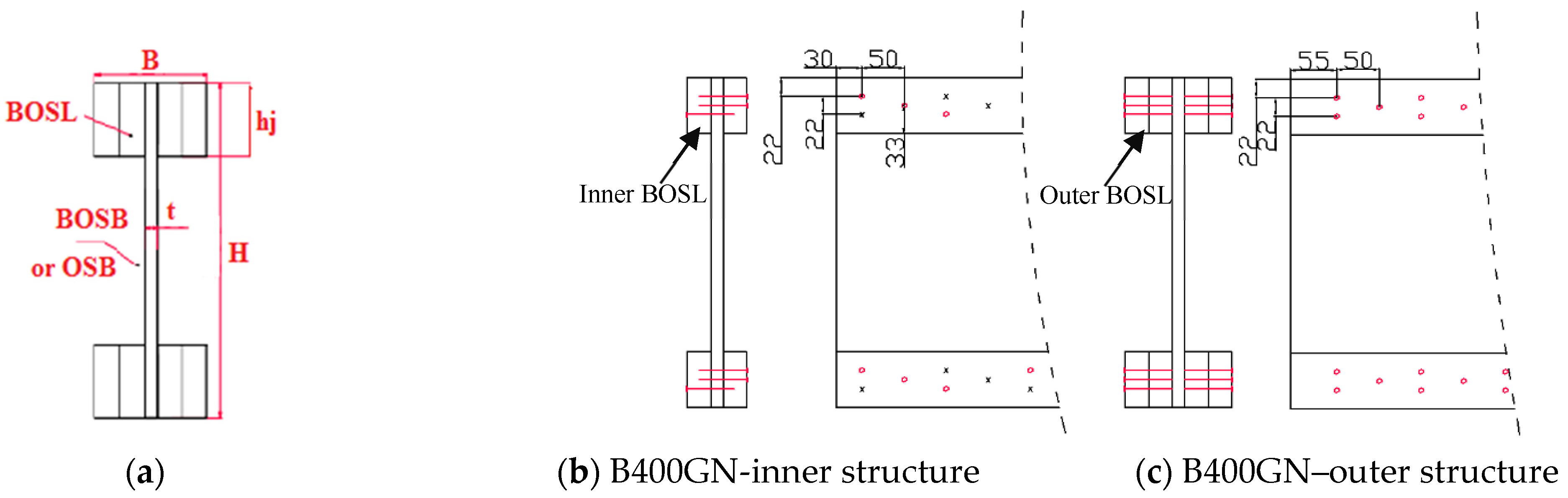
2.2. Preparation of I-Beams
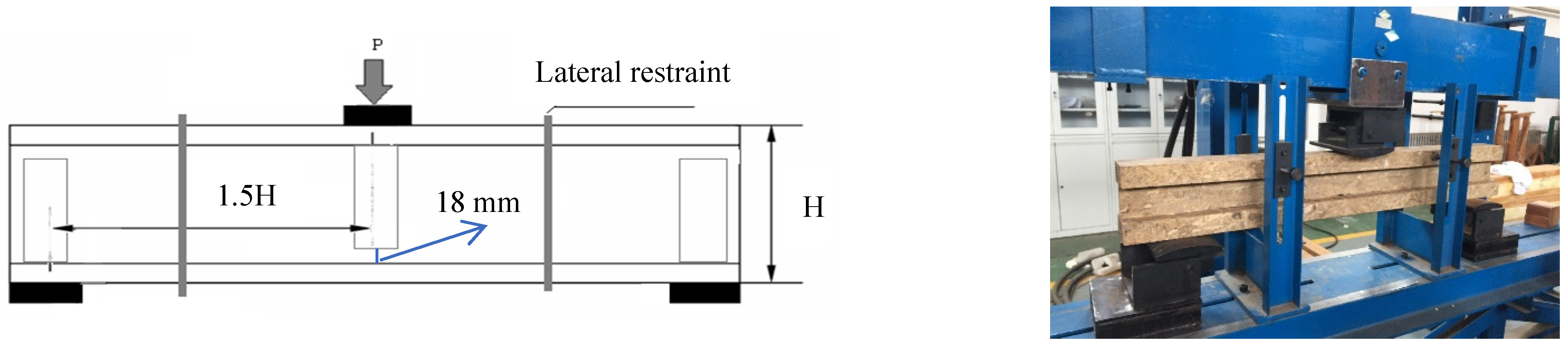
Referring to the common I-beam height in standard PRI-400-2021 [26], combined with the BOSB sheet size specification of 2440 mm (length) × 1220 mm (width) × 15 mm (thickness), the web height was determined to be 300 mm and 400 mm to maximize the utilization of materials. Referring to ASTM D 5055-2016 [27], the I-beam uses BOSL in the flange material, and the height should generally not exceed 1/6 of the total height of the beam. For comparative analysis, the flange height was designed to be 66 mm and the flange width was 127 mm. The scheme and beam dimensions are shown in Table 2.
BOSL flanges, after going through the sanding and adhesive application process, were cold-pressed or nailed at the upper and lower edges to BOSB or OSB panel webs, forming an “I” cross-sectional shape, as shown in Figure 1. Two different assembly approaches were used for joining the flanges and webs of I-beams. Some of the I-beams were cold-pressed with 290 g·m−2 adhesive application under 2 MPa pressure for 4 h. The other I-beams (B400GN) were assembled with nails (diameter, 2 mm; length, 56 mm) driven by a pneumatically operated machine with the same amount of adhesive. For the connection of inner BOSL flanges and BOSB webs in B400GN, 50% of the nails were driven into one side of the member and 50% of the nails were driven into the other side, as shown in Figure 1b. In addition, the inner and outer BOSL flanges in B400GN were glued and nailed together according to the pattern and nail spacing shown in Figure 1c. The specimens used in qualification testing were brought to a moisture equilibrium of 12% in a conditioned environment of 20 ± 6 °C and 65% ± 5% relative humidity. The factors considered in this study were the web types (BOSB and OSB), web to flange joint types (nailing or cold pressing), and depth of the beam (300–500 mm).

2.3. Testing

According to ASTM D 5055-2016 standards [27], the short beam shear tests under three-point loading were conducted under a loading rate of 5 mm·min−1 (Figure 2). The vertical load was applied to the center of the top flange and the span–depth ratio was 3. Flat steel bearing plates (300 mm long and 200 wide) provided the support and vertical load. Two lateral restraints placed at 1/3 span intervals in the tests were provided to prevent the lateral buckling of the compression member. Web stiffeners composed of dimension lumber with a width of 120 mm and a thickness of 38 mm were installed in each I-beam at the points of loading and the supports to prevent bulking (except B400G(2)). Stiffeners were completely fastened to the webs. One end of the stiffeners was adhered to the inner edge of the top or bottom flanges and the gap between the other end of the stiffeners and flange without loading was 18 mm.
According to ISO13586-2018 [28], the ultimate load Fmax (the shear bearing capacity), initial stiffness S, and the load at the initiation of crack growth FQ were determined from the load–displacement curves. The failure modes were recorded according to the testing results. However, for the purposes of evaluating shear performance, bearing failure was also considered as a mode of shear failure. Each specimen had five replicates.
The compressive bearing capacity (VLC) test was carried out according to GB/T 28985-2012 [29]. The test piece was damaged by a uniform pressure load, and the compressive capacity of the test piece was determined. This paper measured the buckling resistance of the web. The length of the test piece was 305 mm, the lengths of the support block and the loading block were larger than the size of the upper and lower flanges of the test piece, the loading speed was 5 mm·min−1, and there were 5 samples for each test condition.

3. Results and Discussions

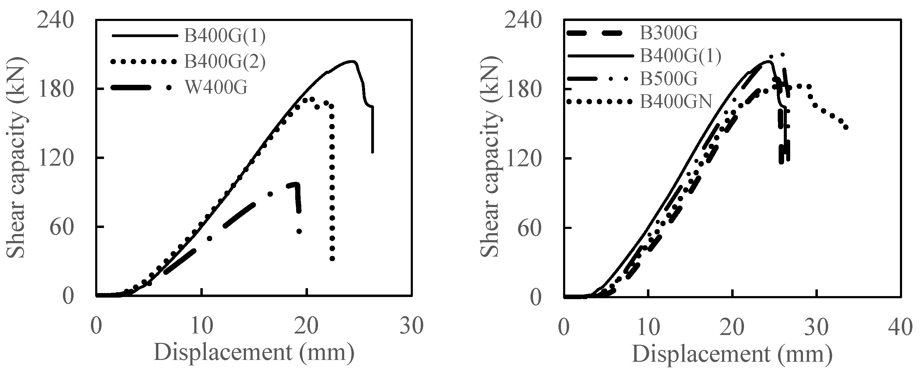
3.1. Influencing Factors of Shear Bearing Capacity
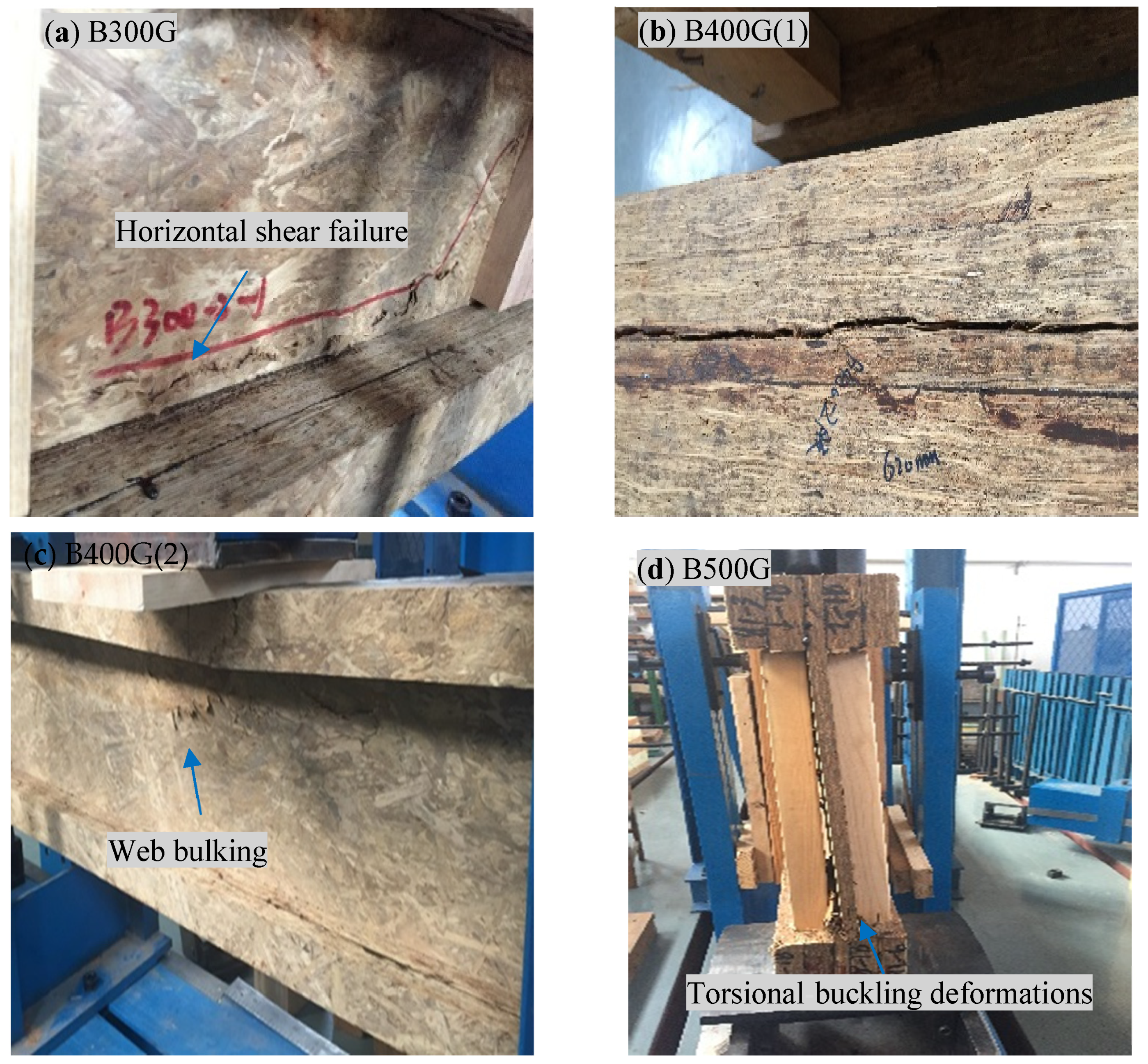
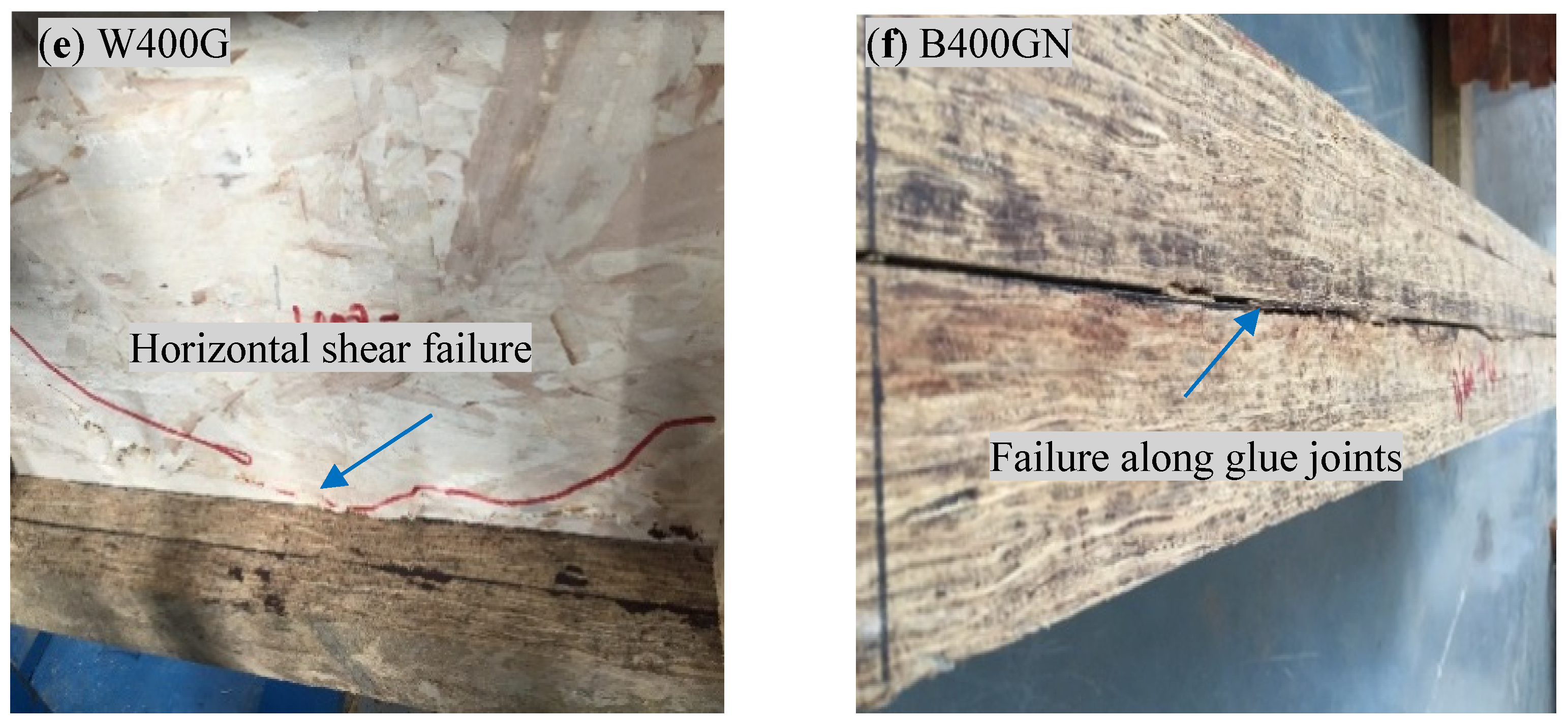
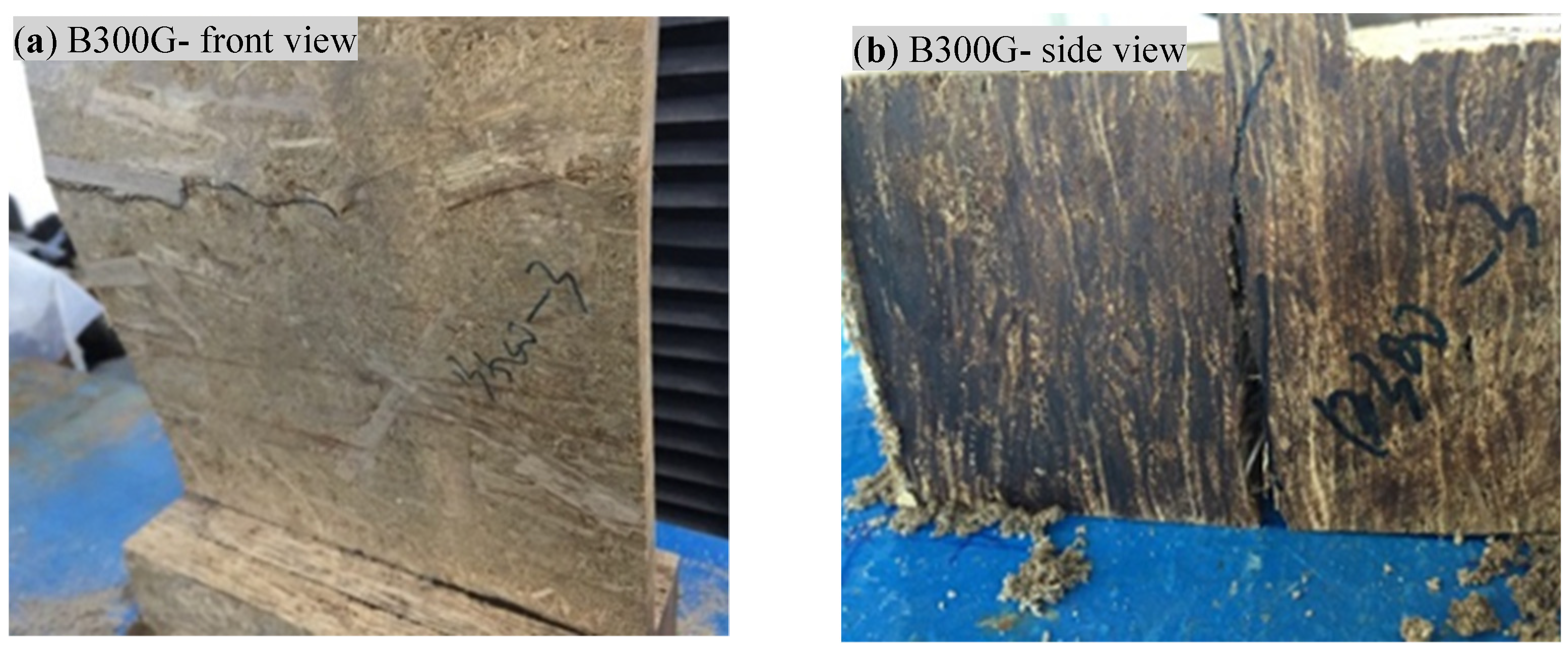
The load–displacement curves of the shearing test on the mid-span I-beams are shown in Figure 3. In the shearing test, the load increased nearly linearly with displacement until it reached the failure load, which indicated brittle failure. The mechanical properties of different I-beams are provided in Table 3. The Fmax, FQ, and S of B400G(1) (BOSB webbed I-beams) were respectively 2.23, 2.25, and 1.70 times the corresponding values of W400G (OSB webbed I-beam), indicating that using BOSB for web remarkably improved the shear bearing capacity of I-beams. The shear through thickness of BOSB was almost two times that of OSB and was consistent with the expected result in short beam shearing test. In addition, the results also proved that the structure of the I-shaped components in this test was reasonable and could withstand relatively large shear stress.
Under the same span–depth ratio, the Fmax and FQ values of B400(1) with stiffeners were significantly higher by 17.11% and 13.73% than those of B400(2) without stiffeners, respectively. Previous studies drew the same conclusion considering the same influencing factors [16]. This may be because stiffeners can improve the local bearing behavior of BOSB web so that the shear performance of BOSB web can be fully utilized.
The short beam shear testing results of B300G, B400G(1), and B500G showed that the shear bearing capacity of I-beams could not be improved by increasing the depth of I-beams with the same flange cross-section. This result was similar to the analysis by Ross and Abdy [30]—when the depth of the beam was in the range of 195–300 mm, the higher-strength specimens did not differ significantly in shear capacity with increasing beam height. The depth of the beam we selected had exceeded this range, but the difference was still not significant. This may be due to the different deformation patterns as the beam height changed, and the torsional buckling of the specimen occurred when the slenderness ratio of the I-beam increased [31,32]. Alternatively, compared with the depth of the I-beam, the flange cross section made a more significant contribution to the overall shear performance of the I-beams. However, in a previous study, the ultimate load capacity of I-beams having the same flange cross-section, but different ratios of span-to-depth, significantly increased with the increase in the I-beam depth in the four-point bending test [33]. This was primarily attributed to the different large ratios of span-to-depth and the coming combined stress condition occurring in the bending.
The effects of joint type on the shear properties of beams were also investigated. For the groups of B400GN, the values of Fmax, FQ, and S of B400GN were 9.94%, 11.22%, and 8.24% lower than those of B400G(1), respectively. The nailed and glued joint type slightly affected the shear properties because a long open assembly time or misfabrication in the nail connections might lead to inadequate adhesive spreading. It was also reported that the strength and stiffness of I-beams with different joint types varied obviously [12].

3.2. Failure Modes

As shown in Figure 4a, for bamboo I-beams with a depth of 300 mm (B300G), the failure modes were dominated by a flange joint split at the end reaction and horizontal shear failure in the web. For bamboo I-beams with a depth of 400 mm (B400G(1)), the main failure modes were bamboo failure along the glue joints and shear failure of the web near the compression flange in the vicinity of the loading point. B400G(2) without stiffeners mainly failed by local web bearing failure at a nearby point of loading. In addition, for B500G with a depth of 500 mm, the torsional buckling of specimens, bamboo failure along the glue joints, and web buckling at the points of supports were observed (Figure 4d). The observed failure modes suggested that the combination of shear stress at the glued joint and webs was the main cause for the failures of I-beams.
Unlike the failure modes of the BOSB webbed I-beam with the same depth, W400G merely experienced a horizontal shear failure located at the end or centerline of the web member. The failure was usually induced by the behaviors of the webs. B400GN experienced the failure of flange joint split at the top flange and web shear failure near the compression flange near the loading point. According to the evaluation results of the glue line quality at the joint failures, wood failure along the glue joints barely reached 30%, indicating the poor bonding effect. This may originate from inadequate assembly pressure and inadequate glue transfer caused by the long open assembly time and misfabrication [27]. It was found in previous research when using glue connection that brittle and undesirable failures occurred [34]. The reason may be that during the fabrication of the test piece, the application of the adhesive may have been uneven, with localized areas of thinly spread adhesive [35]. It was reported in similar results that the failure modes depended on the types of I-beam configurations and web materials [31].

3.3. Simplified Calculation and Analysis for I-Beams

CAS 086-2019 [36] specified equations and data for glued composite building components using OSB or glued laminated timber. The properties of the flange and web material used to calculate the shear bearing capacity of I-beams are provided in Table 1. For the web shear failure, the factored shear bearing capacity, Vr, of the web of a panel beam at its neutral axis is expressed as:
V r = ϕ V P X J   ( E I ) e E K S E Q f + 0.5 (   B a ) K S C w 2
where: ϕ = 0.95; Vp = sum of specified strengths of all panel webs in the shear through thickness, Vp = 19.8 MPa × 15 mm, N·mm−1; XJ = stress joint factor, XJ = 1; E = modulus of elasticity of flange, E = 9,330 MPa; Qf = moment of area of flange about the neutral axis, mm3; ΣBa = sum of specified axial stiffness for all panel webs, ΣBa= 10,250 MPa × 15 mm, N·mm−1; cw = longest distance from the neutral axis to the outer edge of the web, mm. KSE = 1 and KS = 1 in this text.
The effective stiffness, (EI)e, of a panel web beam is expressed as:
( E I ) e = (   B a ) K S ( C t 3 + C c 3 ) 3 + ( E I ) f K S E
where: (ΣBa) = sum of axial stiffness of panel webs, N·mm2; KS = service condition factor for web material; (EI)e = effective stiffness, N·mm2; KSE = service condition factor for modulus of elasticity of flange; cc = distance from the neutral axis to the compression face, mm; ct = distance from the neutral axis to the tension face, mm.
The experimental and calculation results are shown in Table 4. The calculated shear bearing capacity was relatively consistent with the experimental value, and the relative errors (d) should be less than 15% in principle. The results showed that the calculated shear bearing capacity was in relatively good agreement with the experimental values. The difference between the experiment and theory could be caused by variability in the shear through thickness and elastic modulus of the components.

3.4. Uniform Vertical Load Capacity of I-Beams

When the beam depth increased from 300 mm to 500 mm, the uniform vertical load capacity of BOSB webbed I-beams gradually decreased (See Table 3), because the I-beams seriously deflected laterally with deeper I-joists and were not supported with web stiffeners. The uniform vertical load capacity of B400G was about two times that of W400G due to the buckling load capacity of BOSB web plates. The comparison results of B400G and B400GN indicated that the influence of connection type on the uniform vertical load capacity was not significant. The main failure modes included web bulking and horizontal failure along the flange–web joint at the beam end (Figure 5). Uniform vertical load capacity testing of I-beams showed that the local stress effect on the web should be taken into account when designing higher I-beam.

4. Conclusions

Short beam shear tests and uniform vertical load capacity tests were performed to investigate the effects of various factors on the properties of bamboo I-beams, and the following results were obtained:
(1)
The mechanical properties of bamboo I-beams at different depths could even exceed the requirements of performance-rated I-Joists in APA PRI-400-2021. Bamboo I-beams can be applied in industrial or commercial buildings requiring cross-sections with greater depth and the shear bearing capacity largely determines their properties. Furthermore, the calculation equations of the shear bearing capacity of glued composite building components in CAS 086-2019 could partly predict the shear bearing capacity of BOSB or OSB webbed I-beams.
(2)
The shear bearing capacity and stiffness showed no great change as the depth of I-beams having the same flange cross section increased from 300 mm to 500 mm. The flange cross section made a more significant contribution to the overall shear performance of the I-beams. Moreover, the shear bearing capacity and stiffness of W400G were almost 50% of corresponding values of B400G(1) and the failure of W400G merely involved horizontal shear failure in webs. However, BOSB webbed I-beams experienced a combined failure of bamboo failure along the glue joints, shear failure of the web, or torsional buckling.
(3)
When the beam depth increased from 300 mm to 500 mm, the uniform vertical load capacity of the BOSB webbed I-beams gradually decreased. Moreover, the main failure modes included web bulking and horizontal failure along the flange–web joint at the I-beam end.

Author Contributions

Conceptualization, Y.S. and C.S.; methodology, X.Y.; investigation, Y.S., F.H. and Y.G.; writing—original draft preparation, X.Y.; writing—review and editing, Y.S. and F.H. All authors have read and agreed to the published version of the manuscript.

Funding

This research was funded by Zhejiang Province Public Welfare Technology Application Research Project of China (No. LGF21G010002) and sponsored by Guizhou Province 2020 Characteristic Forestry Industry R&D Project (No. GZMC-ZD20202112).

Institutional Review Board Statement

Not applicable.

Informed Consent Statement

Not applicable.

Data Availability Statement

Data are contained within the article.

Conflicts of Interest

The authors declare no conflict of interest.

References

  1. Dixon, P.G.; Malek, S.; Semple, K.E.; Zhang, P.K.; Smith, G.D.; Gibson, L.J. Multiscale Modelling of Moso Bamboo Oriented Strand Board. Bioresources 2017, 12, 3166–3181. [Google Scholar] [CrossRef]
  2. Semple, K.E.; Zhang, P.K.; Smola, M.; Smith, G.D. Hybrid oriented strand boards made from moso bamboo (Phyllostachys pubescens Mazel) and aspen (Populus tremuloides Michx.): Uniformly mixed single layer uni-directional boards. Eur. J. Wood Wood Prod. 2015, 73, 515–525. [Google Scholar] [CrossRef]
  3. Ihak, S.; Kazuhiro, O.; Shigehiko, S. Effect of board density and layer structure on the mechanical properties of bamboo oriented strand board. J. Wood Sci. 2007, 53, 510–515. [Google Scholar] [CrossRef] [Green Version]
  4. Sumardi, I.; Suzuki, S.; Rahmawati, N. Effect of board type on some properties of bamboo strandboard. J. Math. Fundam. Sci. 2015, 47, 51–59. [Google Scholar] [CrossRef] [Green Version]
  5. Viguier, J.; Damien, B. Modelling mechanical properties of spruce and Douglas fir timber by means of X-ray and grain angle measurements for strength grading purpose. Eur. J. Wood Wood Prod. 2017, 75, 527–541. [Google Scholar] [CrossRef] [Green Version]
  6. Sun, Y.; Zhang, Y.; Huang, Y.; Wei, X.; Yu, W. Influence of Board Density on the Physical and Mechanical Properties of Bamboo Oriented Strand Lumber. Forests 2020, 11, 567. [Google Scholar] [CrossRef]
  7. Ar, C.; Plenzler, R.; Ludwiczak-Niewiadomska, L.; Latusek, D. Foli behaviour of OSB-webbed I-beams subjected to short-term loading. Folia For. Pol. Ser. B 2005, 36, 27–37. [Google Scholar]
  8. Ren, X.; Dong, C.; Zhang, H. Influence of Edgewise Shearing Modulus of Elasticity of Web on Static-Bending Deflection of Wood I-Beam. J. Southeast For. Univ. 2011, 31, 61–64. (In Chinese) [Google Scholar]
  9. Davids, W.G.; Rancour, D.G.; Dagher, H.J. Bending performance of composite wood I-joist/oriented strand board panel assemblies. For. Prod. J. 2011, 61, 246–256. [Google Scholar] [CrossRef]
  10. Wu, S.; Yu, L.; Li, J.; Dong, M. Study on Mechanical Properties of Prefabricated Wood I-Beam Wing Edge/Web Interfaces. For. Mach. Woodwork. Equip. 2015, 5, 28–30. (In Chinese) [Google Scholar]
  11. Pozdeeva, A. Stress Distribution in Mechanically Jointed Timber I-Beam. Bachelor’s Thesis, Saimaa University of Applied Sciences, Helsinki, Finland, 2015. [Google Scholar]
  12. Holstein, A.J.; Bohnhoff, D.R. Bending Properties of Wood I-Sections Fabricated with Screws and Polyurethane Adhesive. J. Struct. Eng. 2013, 139, 2019–2027. [Google Scholar] [CrossRef]
  13. Rao, S.; Gong, M.; Chui, Y.H.; Mohammad, M. Effect of geometric parameters of finger joint profile on ultimate tensile strength of single finger-joined boards. Wood Fiber Sci. 2012, 443, 263–270. [Google Scholar]
  14. Wang, G.; Jiang, Z.; Chen, F.; Cheng, H.; Sun, F. Manufacture Situation and Problem Analysis on Large Size Bamboo Engineering Material in China. China For. Prod. Ind. 2014, 411, 48–52. (In Chinese) [Google Scholar]
  15. Paniagua, V.; Moya, R. Flexural performance of I-Joist fabricated with glue-Laminated bamboo and plywood. Open J. Civ. Eng. 2014, 43, 209–216. [Google Scholar] [CrossRef] [Green Version]
  16. Chen, G.; Zhang, Q.; Huang, D.; Li, H. Bending Tests of OSB Webbed Bamboo I-joists. J. Hunan Univ. 2015, 5, 72–79. (In Chinese) [Google Scholar]
  17. Guan, Y.; Xiao, Y. Investigation on bending behavior of glubam I-shaped joint. Ind. Constr. 2016, 46, 79–82. (In Chinese) [Google Scholar]
  18. Zhao, K.; Wei, Y.; Chen, S.; Hang, C.; Zhao, K. Experimental investigation of the long-term behavior of reconstituted bamboo beams with various loading levels. J. Build. Eng. 2020, 36, 102107. [Google Scholar] [CrossRef]
  19. Sun, Y.; Jiang, Z.; Zhang, X.; Sun, Z.; Liu, H. Behavior of glued laminated bamboo and bamboo-oriented strand board sheathing-to-framing connections. Eur. J. Wood Wood Prod. 2019, 77, 1189–1199. [Google Scholar] [CrossRef]
  20. Chen, G.; Tan, C.; Yang, W.; Wu, J.; Zhou, T.; Jiang, H.; Zhang, Y. Wood I-joists with web holes and flange notches: A literature review. J. Build. Eng. 2021, 38, 102224. [Google Scholar] [CrossRef]
  21. Liu, K.; Xu, Q.; Wang, G.; Chen, F.; Leng, Y.; Yang, J.; Harries, K.A. Types and characteristics of bamboo materials for construction uses. In Contemporary Bamboo Architecture in China; Springer: Singapore, 2022. [Google Scholar] [CrossRef]
  22. Chen, S.; Wei, Y.; Zhao, K.; Dong, F.; Huang, L. Experimental investigation on the flexural behavior of laminated bamboo-timber I-beams. J. Build. Eng. 2022, 46, 103651. [Google Scholar] [CrossRef]
  23. Racher, P.; Bocquet, J.F.; Bouchair, A. Effect of web stiffness on the bending behaviour of timber composite I-beams. Mater. Des. 2007, 283, 844–849. [Google Scholar] [CrossRef]
  24. GB/T17657-2013; Test Methods of Evaluating the Properties of Wood-Based Panels and Surface Decorated Wood-Based Panels. GB Standards: Beijing, China, 2013.
  25. CSA/O437.0-93R; Standards on OSB and Waferboard. Canadian Standards Association: Toronto, ON, Canada, 2011.
  26. PRI-400-2021; Performances Standard for Residential I-Joints (Limit States Design). APA-The Engineered Wood Association: Tacoma, WA, USA, 2021.
  27. ASTM D5055; Standard Specification for Establishing and Monitoring Structural Capacities of Prefabricated Wood I-JOISTS. American Society for Testing of Material International: West Conshohocken, PA, USA, 2016.
  28. ISO13586-2018; Plastics-Determination of Fracture Toughness (GIC and KIC)-Linear Elastic Fracture Mechanics (LEFM) Approach. ISO: Geneva, Switzerland, 2018.
  29. GB/T 28985-2012; Wood I-Jiost for Building Structures. GB Standards: Beijing, China, 2013.
  30. Brown, R.J.; Kermani, A. Flange Width Contribution to Shear Strength in Engineered I-Joists. In Proceedings of the 8th World Conference on Timber Engineering, Lahti, Finland, 14–17 June 2004. [Google Scholar]
  31. Fan, M. Performance of wood-based panel I-beam components. In Proceedings of the 11th World Conference on Timber Engineering, Trentino, Italy, 20–24 June 2010. [Google Scholar]
  32. Hindman, D.P.; Bamberg, C.R.; Nussbaum, M.A. Bracing of Wood Composite I-Joists to Resist Lateral Buckling from Walking Loads. J. Constr. Eng. Manag. 2014, 140, 401–403. [Google Scholar] [CrossRef]
  33. Zhu, E.C.; Guan, Z.W.; Rodd, P.D.; Pope, D.J. Buckling of Oriented Strand Board Webbed Wood I-Joists. J. Struct. Eng. 2005, 131, 1629–1636. [Google Scholar] [CrossRef]
  34. Wahan, M.Y.; Zhang, Z.; Meng, X.; Gao, Y.; Ji, X. Mechanical behavior of gfrp-bamboo composite shear connections. Constr. Build. Mater. 2022, 331, 127333. [Google Scholar] [CrossRef]
  35. Duan, Y.; Zhang, J.; Tong, K.; Wu, P.; Li, Y. The effect of interfacial slip on the flexural behavior of steel-bamboo composite beams. Structures 2012, 32, 2060–2072. [Google Scholar] [CrossRef]
  36. CSA 086-2019; Engineering Design in Wood. National Standard of Canada: Ottawa, ON, Canada.
Figure 1. Details of I-beam: (a) I-beam cross section; (b) side and front view of the inner BOSL connection type in B400GN; (c) side and front view of the outer BOSL connection type in B400GN.
Forests 13 00826 g001
Figure 2. Shear test loading device and schematic diagram.
Forests 13 00826 g002
Figure 3. Typical load–displacement curve of test specimens.
Forests 13 00826 g003
Figure 4. I-beam failure modes in the short beam shear test.
Forests 13 00826 g004aForests 13 00826 g004b
Figure 5. Uniform vertical load test failure of B300G.
Forests 13 00826 g005
Table 1. Mechanical properties of individual materials.
MaterialMOR // (MPa)MOR ⊥ (MPa)MOE // (GPa)MOE ⊥ (GPa)Shear through Thickness (MPa)
BOSB82.56 (12.49%)36.90 (14.02%)10.25 (6.46%)3.97 (7.10%)19.8 (13.43%)
BOSL66.91 (10.61%)28.93 (11.91%)9.33 (5.07%)3.99 (5.14%)16 (14.6%)
OSB35.55 (20.92%)13.17 (19.14%)3.43 (21.39%)1.22 (14.05%)9 (8.95%)
Note: modulus of rupture (MOR); modulus of elasticity (MOE); // (parallel to surface strand alignment directions); ⊥ (perpendicular to those). The tabulated values are average values, and the values in parentheses are the coefficient of variation.
Table 2. Experimental design of I-beams.
TypesBeam Length (mm)Beam Depth (H) (mm)Web TypesWeb to Flange Joints TypeWith Stiffeners
B300G2100300BOSBCold press (without nails)With
B400G(1)2400400BOSBCold press (without nails)With
B400G(2)2400400BOSBCold press (without nails)Without
B400GN2400400BOSBNailed and gluedWith
B500G2440500BOSBCold press (without nails) With
W400G2400400OSBCold press (without nails)With
Table 3. Experimental parameters of different I-beams.
Beam TypesFmax (kN)FQ (kN)S (kN·m−1)VLC (kN·m−1)
B300G186.77 (7.67%)182.28 (12.31%)11.35 (10.54%)354.57 (4.09%)
B500G198.94 (8.6%)196.97 (8.76%)11.0 (1.02%)214.44 (22.92%)
B400G(1)202.97 (10.6%)194.87 (11.58%)11.73 (18.61%)286.89 (27.90%)
B400G(2)173.32 (8.98%)171.35 (8.47%)11.07 (12.1%)286.89 (27.90%)
B400GN184.62 (9.7%)175.204 (12.3%)10.8366 (3.97%)241.01 (16.72%)
W400G91.18 (10.88%)86.46 (10.31%)6.88 (5.22%)123.23 (18.76%)
Note: ultimate load Fmax (shear bearing capacity); initial stiffness (S); load at initiation of crack growth (FQ); uniform vertical load capacity (VLC). The tabulated values are average values, and the values in parentheses are the coefficient of variation.
Table 4. Comparison between the predicted cross-section stiffness and experimental results.
Beam TypesCalculated Results (Vr) (kN)Experimental Results (Fmax) (kN)d (%)
B300G158.14186.7715.33%
B500G214.44198.94−7.79%
B400G(1)184.33202.979.18%
B400GN184.33184.620.16%
W400G100.2891.18−9.98%
Note: d = (Fmax − Vr)/Fmax × 100%.
Publisher’s Note: MDPI stays neutral with regard to jurisdictional claims in published maps and institutional affiliations.

