Article

A Sustainable Approach to Build Insulated External Timber Frame Walls for Passive Houses Using Natural and Waste Materials

by
Sergiu-Valeriu Georgescu
1,
Daniela Șova
2,
Mihaela Campean
1 and
Camelia Coșereanu
1,*
1
Faculty of Furniture Design and Wood Engineering, Transilvania University of Brasov, B-dul Eroilor nr. 29, 500036 Brasov, Romania
2
Faculty of Mechanical Engineering, Transilvania University of Brasov, B-dul Eroilor nr. 29, 500036 Brasov, Romania
*
Author to whom correspondence should be addressed.
Forests 2022, 13(4), 522; https://doi.org/10.3390/f13040522
Submission received: 25 February 2022 / Revised: 20 March 2022 / Accepted: 23 March 2022 / Published: 28 March 2022
(This article belongs to the Special Issue Novelties in Wood Engineering and Forestry)

Abstract

:
This paper presents structures of timber-framed walls designed for passive houses, using natural and waste resources as insulation materials, such as wool, wood fibers, ground paper, reeds (Phragmites communis), and Acrylonitrile Butadiene Styrene (ABS) wastes. The insulation systems of stud walls composed of wool–ABS composite boards and five types of fillers (wool, ABS, wood fibers, ground paper, and reeds) were investigated to reach U-value requirements for passive houses. The wall structures were designed at a thickness of 175 mm, including gypsum board for internal wall lining and oriented strand board (OSB) for the exterior one. The testing protocol of thermal insulation properties of wall structures simulated conditions for indoor and outdoor temperatures during the winter and summer seasons using HFM-Lambda laboratory equipment. In situ measurements of U-values were determined for the experimental wall structures during winter time, when the temperature differences between outside and inside exceeded 10 °C. The results recorded for the U-values between 0.20 W/m2K and 0.35 W/m2K indicate that the proposed structures are energy-efficient walls for passive houses placed in the temperate-continental areas. The vapour flow rate calculation does not indicate the presence of condensation in the 175 mm thick wall structures, which proves that the selected thermal insulation materials are not prone to degradation due to condensation. The research is aligned to the international trend in civil engineering, oriented to the design and construction of low-energy buildings on the one hand and the use of environmentally friendly or recycled materials on the other.

1. Introduction

According to the European Commission, 40% of energy consumption and 36% of greenhouse gas emissions in the European Union belong to buildings, mainly from their construction, usage, renovation, and demolition. By renovating existing buildings, the total energy consumption in the EU could be reduced by 5–6% and CO2 emissions by about 5% [1]. About 35% of EU buildings are now over 50 years old and their energy efficiency is low [2]. In order to increase the energy efficiency of buildings, it is necessary to reduce energy consumption and CO2 emissions, aiming for the goal of carbon-neutrality by 2050, an essential priority in tackling the climate change and environmental degradation [3]. The materials of energy-efficient houses must reach certain values of the heat transfer coefficient depending on the climatic zone in which they are used, according to the criteria of Passive House Institute (PHI) for low energy buildings [4]. Passive houses are a concept developed in Darmstadt, Germany for sustainable architecture, and their design involves adapting to the climate. A sustainable home involves the characteristics of both green and passive houses, as well as environmentally friendly technologies. Passive houses are characterized by a very good thermal insulation of the exterior walls, expressed by the heat transfer coefficient or by thermal transmittance. For the continental temperate zone specific to Romania, the recommended thermal transmittance (U) for exterior walls is between 0.30 W/m2K and 0.50 W/m2K according to the criteria of passive houses issued by certification by PHI [4].
Current trends in civil engineering are the design and construction of low-energy buildings on the one hand and the use of environmentally friendly or recycled materials on the other. Natural or recycled materials are more and more investigated for their use as insulation materials. Reeds, bagasse, kenaf, cattail fibers, corn’s cob, cotton stalk fibers, date palm, and sunflower are just few examples of natural resources used as raw materials for thermal-insulating structures [5,6,7,8,9,10,11,12]. The natural materials have the advantage of being renewable and ecological resources with low densities, good thermal properties, and low costs. Instead, they have drawbacks, such as hygroscopic properties and low anti-fungal and fire resistance, which can be attenuated by their chemical treatments [13]. Recently, the public perception of the presence of plastic in the environment has changed, and there is a growing international concern for improving the management of this material at the end of the life cycle of the products that use it. One of the recommended solutions is the use of bio-plastics [14], another is recycling [15]. ABS and polyethylene are known as thermoplastics with a long period of biodegradation. Therefore, these materials are on the list of those for which recycling options are sought [16].
The trend of bringing environmentally friendly materials back into building construction is becoming more pronounced in the international community. Greenery systems are considered passive tools for energy savings in buildings and for acoustic insulation [17,18,19]. Reed is considered a renewable resource with high potential as thermal insulator [20,21], even if in situ measurements of moisture content in various climate conditions correlated with thermal conductivity coefficient demonstrated the sensitivity to moisture of this material, to the detriment of thermal insulating performance [22]. Reed is also a carbon-neutral raw material and a CO2, sink and it has been used for centuries for various uses, including vernacular architecture [23]. Spruce bark, available in large quantities and not used with a high value added, was investigated as insulating filling material in external timber frame wall structure, resulting in potential thermal insulator [24] and mixed pine tree bark and cannabis residues glued with two different adhesives formed boards with good insulation properties [25]. Tree bark is suitable for thermal insulation material due to its low density, very good thermal insulation properties, a high proportion of cork cells, high chemical extractives content serving as a protection against microorganisms, and low flammability [13,26]. Wood fibers resultant from low-quality wood are also a part of the insulation materials market, being used to produce wood fiber insulation boards through various methods, such as incubating with laccase–mediator system and then hardened with steam–air mixture [27], or applying the wet process for the low-density bark fibre boards without using additives or adhesive [28]. Wool is another natural material that is insufficiently introduced into the economic circuit. Wool is a performant thermal insulation material, due to its unique property of accumulating the moisture fully in the central part and simultaneously keeps the hydrophobic surface shelves dry, thus offering dry and warm surfaces with high thermal resistance [29]. Being also a biodegradable material, wool is an alternative solution to green buildings construction [30,31]. The high ability of wool to absorb moisture up to 35% prevents condensation and recommends this material to be used as an insulated material both for building walls and roofs [32]. One of the most important advantages of natural materials, such as fibers originating from vegetable sources, or animals fibers including wool, is that they involve low carbon emissions and energy for manufacture and transport. They can also buffer the humidity, mitigate moisture, and improve indoor air quality, allowing the building to “breathe” [33]. The environmental and health impact of the natural materials is also low, as long as they allow binding into thermal insulation boards without chemical adhesives, as in the case of using agro-wastes [34,35,36] or other unconventional resources [37]. Paper waste and recycled paper are also alternative solutions for a sustainable market of thermal insulation boards [38].
In addition to the determination by laboratory measurement of thermal resistance and thermal conductivity coefficients, in situ experimental methods for determining the heat transfer and for measuring thermal transmittance are also applied in some research works. Thermocouples and sensors are placed inside and outside the walls, and heat flow meters are used on the inner surface, or inside the wall structures for in situ measurements [39,40,41,42]. Another research work compared the in situ measurement method and a method based on simulation software applied on timber frame wall with several insulation materials and investigated characteristics such as humidity and condensation [43]. Additionally, the vapour transfer through various types of materials should not be neglected and is the object of investigation in several research works in order to assess the condensation risk inside the structure [44] and mould growth [45,46]. Vapour transfer through various materials and at various surfaces using classical numerical method is also addressed [47]. Coupled vapour and heat transfer under real climate conditions [48] combined with classical numerical methods have shown that the heat flow through the wall was influenced by the vapour flow crossing the insulation materials with high hygroscopic characteristics (wood fibre and cellulose).
The investigation of insulation materials for building construction comprised a large amount of natural resources and recycled wastes in order to achieve both resource and energy sustainability in this sector [49]. All investigated materials for the building sector may have a role in the construction of panels, walls, and roofs, depending on the individual properties of each material. The present study investigates the thermal insulation properties and the presence of condensation in the 175 mm thick external timber frame walls designed for passive houses, for which the recommended thermal transmittance (U) of the exterior walls ranges between 0.30 W/m2K and 0.50 W/m2K. Wood fibers and renewable natural materials insufficiently introduced into the economic circuit, such as wool and reeds, but also recyclable materials such as plastic or paper are used as insulation materials inside the wall structures. The study’s approach is based both on laboratory and in situ measurements of the thermal behaviour of the experimental walls and the comparison of their thermal performances.

2. Materials and Methods

2.1. Insulation Materials

Five materials were used in this study as insulation materials in the structure of external timber frame walls, composed (beginning from the inner face to the outer face) of 12 mm gypsum board (GB), 0.2 mm thick aluminium foil used as a vapor barrier, insulation materials, and oriented strand board (OSB) of 12.5 mm. The insulation materials were as follows: Acrylonitrile Butadiene Styrene (ABS) waste, wool, wood fibers, reed, and recycled paper. ABS waste was in the form of small particles, which resulted from the edge banding machine, after edging the sides and ends of wood-based materials used in furniture production, such as medium density fiberboard (MDF) or particleboard. A mixture of wt. 40% wool (as reinforcement) and wt. 60% ABS (as matrix) was used to form thermal insulation panels with sizes of 564 mm × 564 mm × 20 mm. The thermal insulation panels were obtained by hot pressing at a temperature of 160 °C and without pressure for 20 min. First, the two components were mixed together, and then the mixture has been arranged inside a wooden frame and covered with a heat-resistant foil on both sides, to avoid sticking the composition to the press plates (Figure 1). The panels were afterwards conditioned, for 48 h, at constant temperature of 20 °C and relative humidity of air of 65% and afterwards sized to the final dimensions.
Wood fibers (FL) were provided by MDF manufacturer S.C. Kastamonu S.A. from Reghin, Romania and the common reed stems (R) were collected from the Danube Delta. Sheep wool (W) was purchased directly from a local sheep farmer. Strips of approx. 15 cm of wool were subjected to manual combing. Recycled paper (P) was soaked in water, then collected into small pieces and squeezed, then dried and ground with a hammer mill. All these materials, including ABS waste were used as fillers, one by one, inside the structure of the experimental wall. Moisture content was around 6.1% for wood fibers, 6% for the reed, and 3.2% for the ground paper. Bulk density (ρ) and thermal conductivity coefficient (λ) were determined for all these materials, including ABS–wool panel, and presented in Table 1. The thermal conductivity coefficient values were measured under the laboratory conditions by using HFM 436 Lambda equipment (NETZSCH-Gerätebau GmbH, Selb, Germany).

2.2. Timber Frame Wall Structure

Five experimental wall structures with length of 600 mm, width of 600 mm, and thickness of 175 mm were designed and built for thermal insulation properties investigation. The designed structures of the walls are presented in Figure 2.
As seen in Figure 2, the insulation materials used inside the wall are structured into seven layers. Thus, three ABS–W composites were placed equidistantly between the two faces of the wall. Empty spaces were loosely filled in successively with the five materials selected for the experiment. The design of the experimental walls is presented in Table 2. Two replicates were built for each type of structure, one for in situ measurements and the other for measurements under laboratory conditions.

2.3. Thermal Transmittance

The five types of experimental wall structures were subjected to thermal transmittance (U) measurements in real conditions (in situ) and the other five were tested under laboratory conditions for thermal resistance (R) measurements. The laboratory tests were conducted on HFM436 Lambda equipment (NETZSCH-Gerätebau GmbH, Selb, Germany), according to ISO 8301:1991 [50] and DIN EN 12667:2001 [51]. This testing method is based on the determination of the quantity of heat that is passed from a hot plate to a cold plate through the sandwich composite structure of the experimental wall (in our case), based on Fourier’s Law. Before the samples were tested, the equipment was calibrated and the temperature configuration was set up, as presented in Table 3.
The temperature configuration intended to simulate the difference of temperature between indoor and outdoor environment, assumed to be equal to the temperature difference ΔT (Table 3). Thus, the top plate was set to a temperature (T2) of 20 °C, to represent indoors, whilst the temperature of the bottom plate (T1) was set to vary between −10 °C and 15 °C, simulating the outdoor environment. Six measurements of thermal conductivity coefficient (λ) and thermal resistance (R) were conducted in the experiment for each wall structure, for the six temperature differences (∆T) varying from 5 °C up to 30 °C. The thermal resistance (R) values resulted from the laboratory measurements of the wall structure were used to calculate the theoretical thermal transmittance or overall heat transfer coefficient (U) using Equation (1), according to ISO 6946:2017 [52].
U = 1 R , ( W / m 2 K )
For the thermal transmittance measured in real conditions (in situ), temperature and heat flow sensors were used, using the Thermozig BLE system from OPTIVELOX, Province of Prato, Italy. Thermozig BLE is professional equipment which measures thermal transmittance (U-value) through the use of a Bluetooth Low Energy sensors network. This system can be configured to a network up to eight measurement nodes and has applications in temperature, thermal flux, or humidity measurements. It uses the automatic recording mode and downloading the data in PC, being supplied with a software package that easily allows generating technical reports with graphics and numerical values. Each test was performed for a minimum period of seven days. According to the user manual recommendations, for accurate results a temperature difference of at least 10 °C between the indoor and outdoor environment was needed, so the tests were conducted during the winter. The positioning of the structures and the sensors are highlighted in Figure 3.

2.4. Vapour Transfer

The method of calculation the vapour flow rate per unit area (vapour flux) was used to verify if condensation occurs in the tested wall structures. If the variation lines of the vapour partial pressures (pv) intersect the variation curves of the saturation pressures (ps), it means that there is an area in the wall where water vapour can condense. This phenomenon can lead to degradation of fillers and increased heat exchange, which causes a decrease in thermal insulation properties.
The determination of the heat flux through a flat wall will allow the determination of linear temperature variations of the vapour partial pressures for each layer thickness of the wall. The variations of the partial pressures of water vapour on the thickness of each layer are compared with the variations of the saturation pressures on the thickness of each layer. If they do not intersect, it means that the temperature in any plane of the wall is higher than the dew point.
Heat flux, unit vapour flux, variations of temperatures, and partial pressures were calculated for each tested wall structure based on a climatic scenario, and will be exemplified by graphical representations.
If the wall delimits the indoor environment (which is air) from the outdoor environment (air), which have different temperatures, a heat transfer occurs from the higher temperature environment to the lower temperature environment. In this case, an overall heat transfer occurs, and the heat flux is expressed by the Equation (2):
q = t i t e R t o t = t i t e R s i + R p + R s e [ W m 2 ]
where ti is the average temperature of the indoor environment, in °C; te is the average temperature of the external environment, in °C; Rtot is the total thermal resistance, in m2K/W; Rsi is the thermal resistance of the inner surface, in m2K/W; Rse is the thermal resistance of the outer surface, in m2K/W; and Rp is the thermal resistance of the wall, in m2K/W.
The vapour flux (qv) is the amount of water vapour in the air transferred per unit time through the unit area of a wall. It can be expressed in terms of the vapour partial pressure on the boundary surfaces of the wall and the resistance to vapour transfer on the wall thickness. The vapour transfer is achieved through the wall in the direction of decreasing the partial vapor pressures and is calculated using Equation (3).
q v = P v 1 P v 2 R v   [ kg m 2 s ]
where Pv1 is the vapour partial pressure on the inner surface of the wall, in Pa; Pv2 is the vapour partial pressure on the outer surface of the wall, in Pa; and Rv is the resistance to vapour transfer, in m/s.

2.5. Statistical Analysis

The obtained values were statistically processed, by determining the standard deviation, for a confidence interval of 95% and an alpha error of 0.05. The standard deviation was also applied to the graphs obtained in Microsoft Excel. One-way Analysis of Variance (ANOVA) was performed with Microsoft® Excel package in order to analyse the significance of the factors affecting the thermal performance of the investigated structures in terms of thermal resistance (R) and thermal transmittance (U-value).

3. Results and Discussions

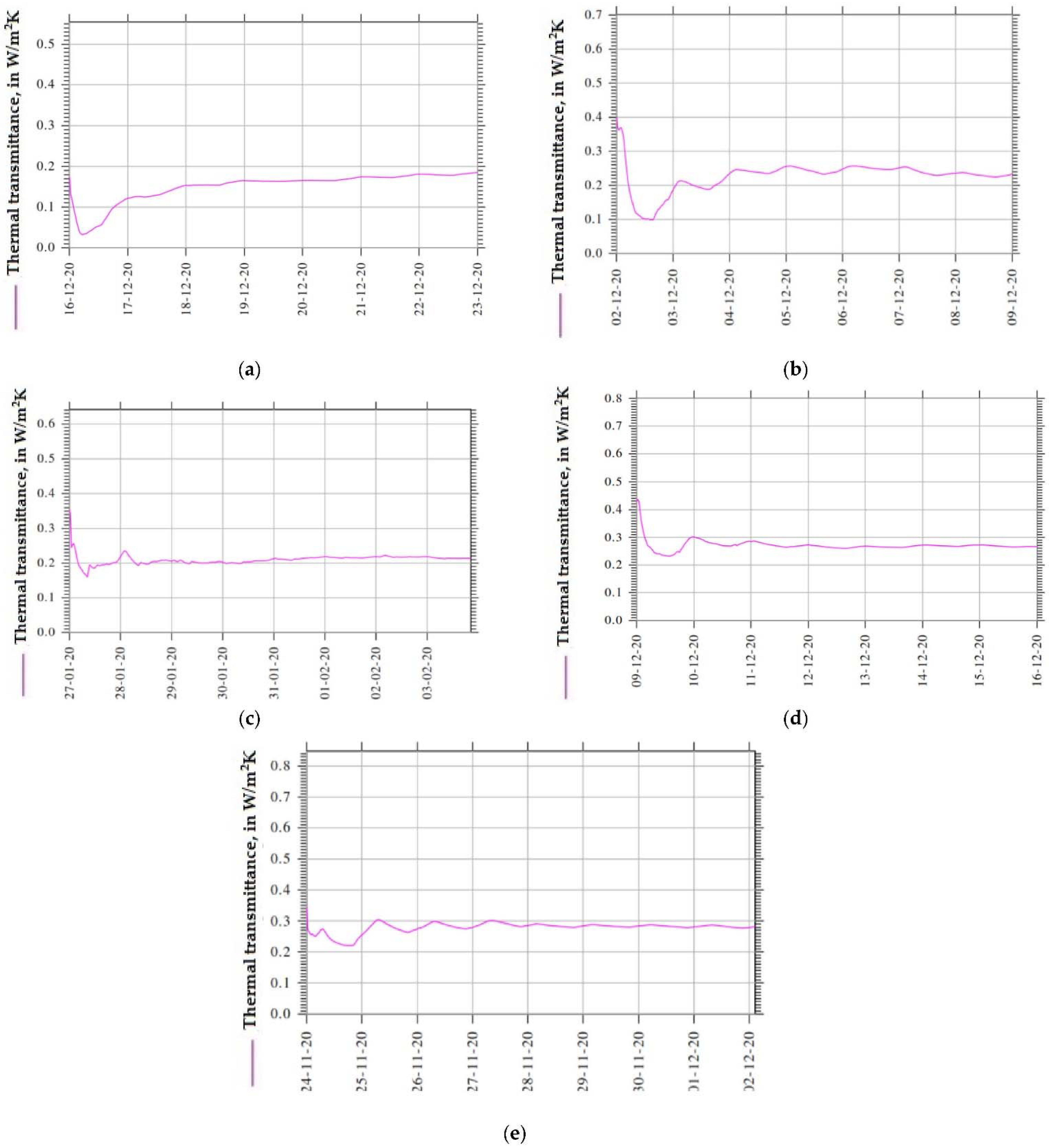
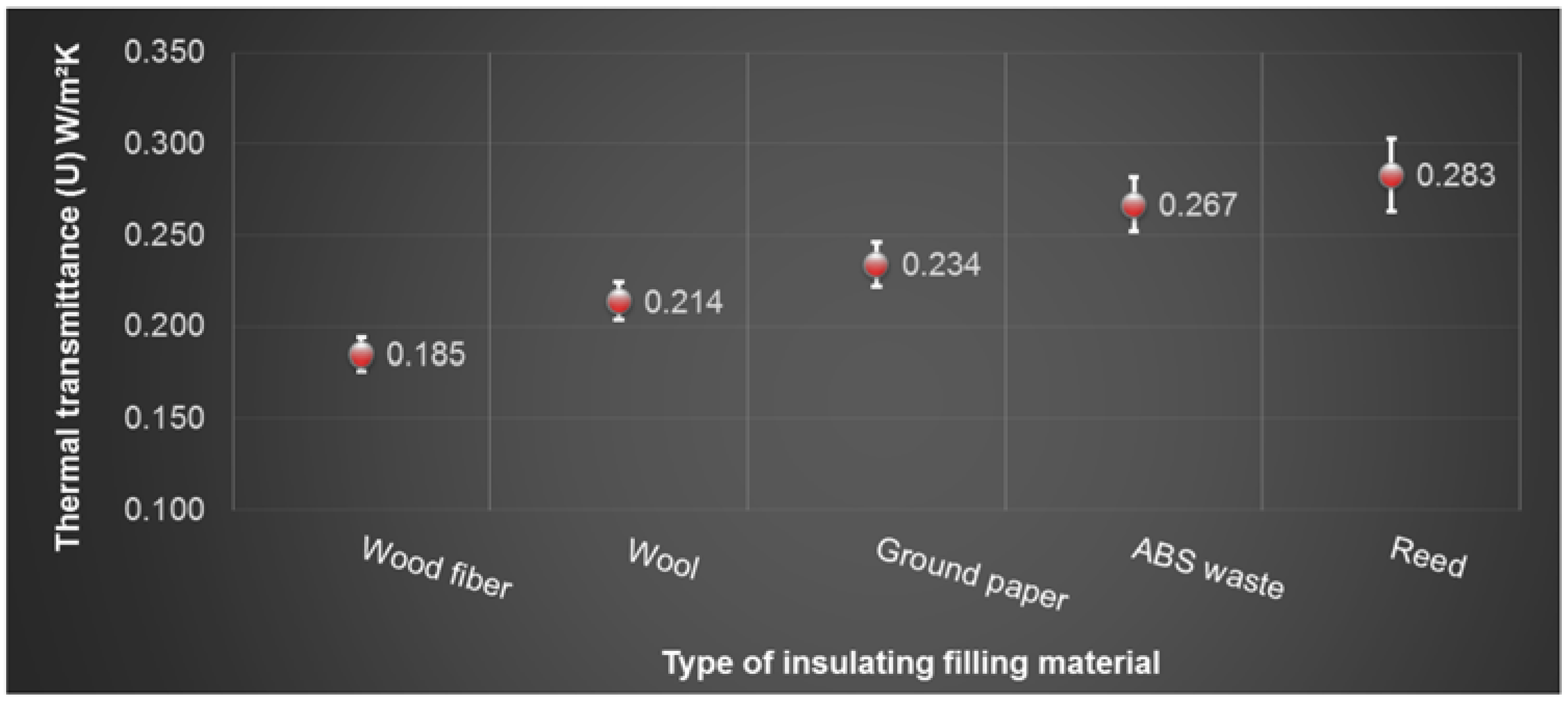
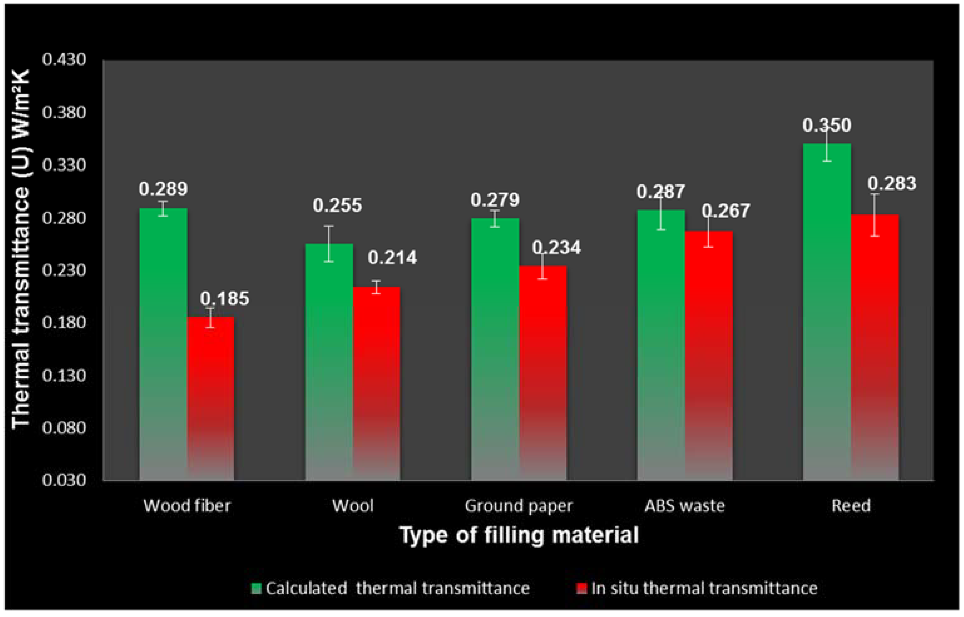
3.1. Thermal Transmittance

The results of the thermal transmittance (Ui) generated by in situ measuring system with temperature and heat flow sensors are presented in Figure 4. The measurements were recorded for seven days, when differences between indoor and outdoor temperatures exceeded 10 °C. In the first hours of testing performance, there was a balancing of the measuring sensors, resulting in a greater variation of the U values. These hours were needed for the calibration of the system. After the system was stabilized, and the graph lines tended to a constant value (after approximately 1 day) the recorded Ui values were used to calculate the mean Ui value.
The Ui mean values of all experimental wall structures and their standard deviations are presented in Figure 5 in ascending order. As observed, the lowest U-values were obtained by the structures with wood fiber and wool fillers. They were followed by the structures with ground paper, ABS, and reed fillers.
The calculated thermal transmittance value (Uc) with Equation (1) was based on the measurement of thermal resistance (R) under the laboratory conditions by means of Netzsch Lambda heat flow meter. The values were recorded for all six temperature configuration setups and ΔT ranging between 5 °C (corresponding to warm season simulation) and 30 °C (corresponding to cold season simulation). The results are presented in Figure 6. As the graph shows, the thermal insulation performance of the fillers is better in warm seasons. Similar results were obtained for wood fibers filler [53].
The structures are not homogeneous, so they did not have a predictable behaviour (increase or decrease) of thermal resistance considering the variation of the experimental setup conditions. The negative temperatures impact on the structures caused the lowering of the thermal resistance. As the graph in Figure 6 shows, the behaviours of the wall structures are similar, regardless of filling material. Instead, the thermal resistance is influenced by the thermal insulation performance of the fillers. For the laboratory measurements, wool filler in the wall structure determined the higher thermal resistance of the investigated timber frame wall and implicitly a better Uc value.
In order to compare the calculated U values (Uc) with measured in situ values (Ui), the thermal resistance (R) recorded for ΔT = 10 °C was used for Uc calculation. This thermal resistance was selected due to the close values of the temperature differences with those from the measurements taken in real conditions (in situ). The comparison between Uc and Ui for all experimental wall structures is shown in Figure 7. As seen from the diagram, the calculated U values are higher than those measured in real conditions for seven days. These differences ranged between 7.64% (structure with ABS waste filler) and 56.3% (structure with wood fibers filler). This result contradicts the conclusions of other research work [54], where the calculated U value was lower than the measured in situ one (with one exception). The differences between calculated and in situ values of thermal transmittance in the mentioned research ranged between 15% and 43%. The theoretical calculation in this case was made using the thermal resistance of each component of the wall structure.
There are several factors that can determine the differences between Uc and Ui values. There are more variables that cannot be controlled in the real climatic conditions. One of these variables is the temperature. The differences between inside and outside temperatures are not constant in real conditions and they could vary from one hour to another. Instead, the measuring protocol with HFM LAMBDA 436/6 installation is based on constant differences of temperatures. Another factor that can influence in situ measurements is the accuracy of the heat flow sensors. The measurement accuracy of the thermal flow sensor of the Ble thermosig device is ±5% (T = 20 °C), whilst the HFM Lambda 436/6 installation accuracy of the entire measurement is ±1% to 3% according to the user manual. An important variable not considered in the present experimental research was the relative humidity of air. In this direction, research on 336 mm thick wall structures, with mineral wool, basalt wool, and hemp fillers as insulation materials [55] proved that, in the closed vapour diffusion layers (mineral and basalt wool), the thermal conductivity coefficient was kept almost constant, while in the hemp layer (considered to be open diffusion), the thermal conductivity coefficient increased by 30% due to moisture transport. As found in the literature, natural materials such as fibers originated from vegetable sources or animal fibers, including wool, can buffer the humidity, mitigate moisture, and allow the building to “breathe” [33]. This advantage may be constrained when the wall structure is placed between the plates of the heat flow meter installation and the humidity is practically trapped inside the structure, possibly influencing the heat transfer. This phenomenon was observed inside the walls with spruce wood faces and 140 mm thick wood fiber and hemp core. As the temperature increased, the wood in the structure released free water and the humidity of the air also increased [56]. In Figure 7, it can be seen that for the structure with ABS (considered to be closed diffusion) filler, the difference between Ui and Uc is smaller than for the other materials, which can be considered open diffusion. As mineral and basalt wool [55], ABS can be less sensitive to humid air, perhaps explaining the low difference between Ui and Uc of only 7.64%.
The external timber frame walls with thickness of 175 mm investigated in this paper have better U-values (0.185–0.283 W/m2K) than those measured in situ for 510 mm thick walls (from which 350 mm were represented by reed panels) [20] and for which the recorded U-values ranged between 0.207 W/m2K and 0.383 W/m2K. Better U-values were obtained for wall structures consisting of wheat straw bales [21] with a thickness of 900 mm, which recorded in situ measured U-value of 0.125 W/m2K. Comparing the ratios between the thickness of the walls and corresponding U-values with those presented in [20,21], it can be stated that the wall structures proposed in the present research have good thermal performances. Laboratory readings of U-values for light-frame timber wall structures with various insulation materials and their combinations (extruded and expanded polystyrene, stone wool, mineral wool, and glass wool) and a total thickness of 160 mm [43], in the conditions of indoor temperature of 20 °C and outdoor temperature around 8 °C ranged between 0.394 W/m2K and 0.419 W/m2K. These results can be compared with those calculated at ΔT = 10 °C in the present research, for which U-values varied between 0.289–0.350 W/m2K, but for a thicker structure of wall of 175 mm.

3.2. Statistical Analysis

Thermal transmittance (U) was statistically significantly (p < 0.05) affected by the applied method of investigation and the bulk density of the fillers. Instead, the differences of temperatures (ΔT) between hot plate and cold plate of the heat flow meter, simulating conditions of cold and warm season, did not show a significant effect (p = 0.278) on the thermal resistance (R) in this investigation where the measurements were conducted in the laboratory conditions, using LAMBDA 436/6 heat flow meter equipment.

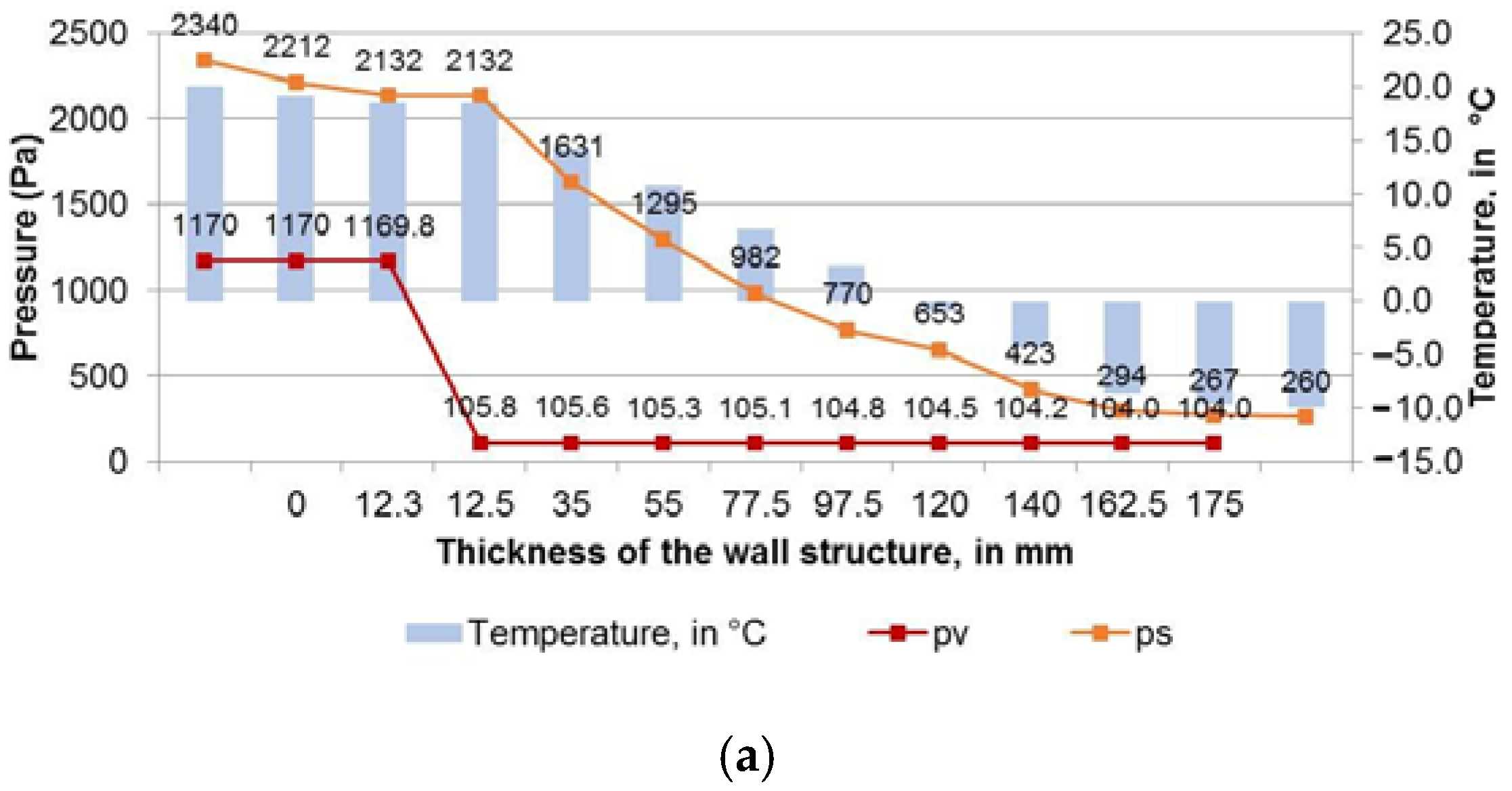
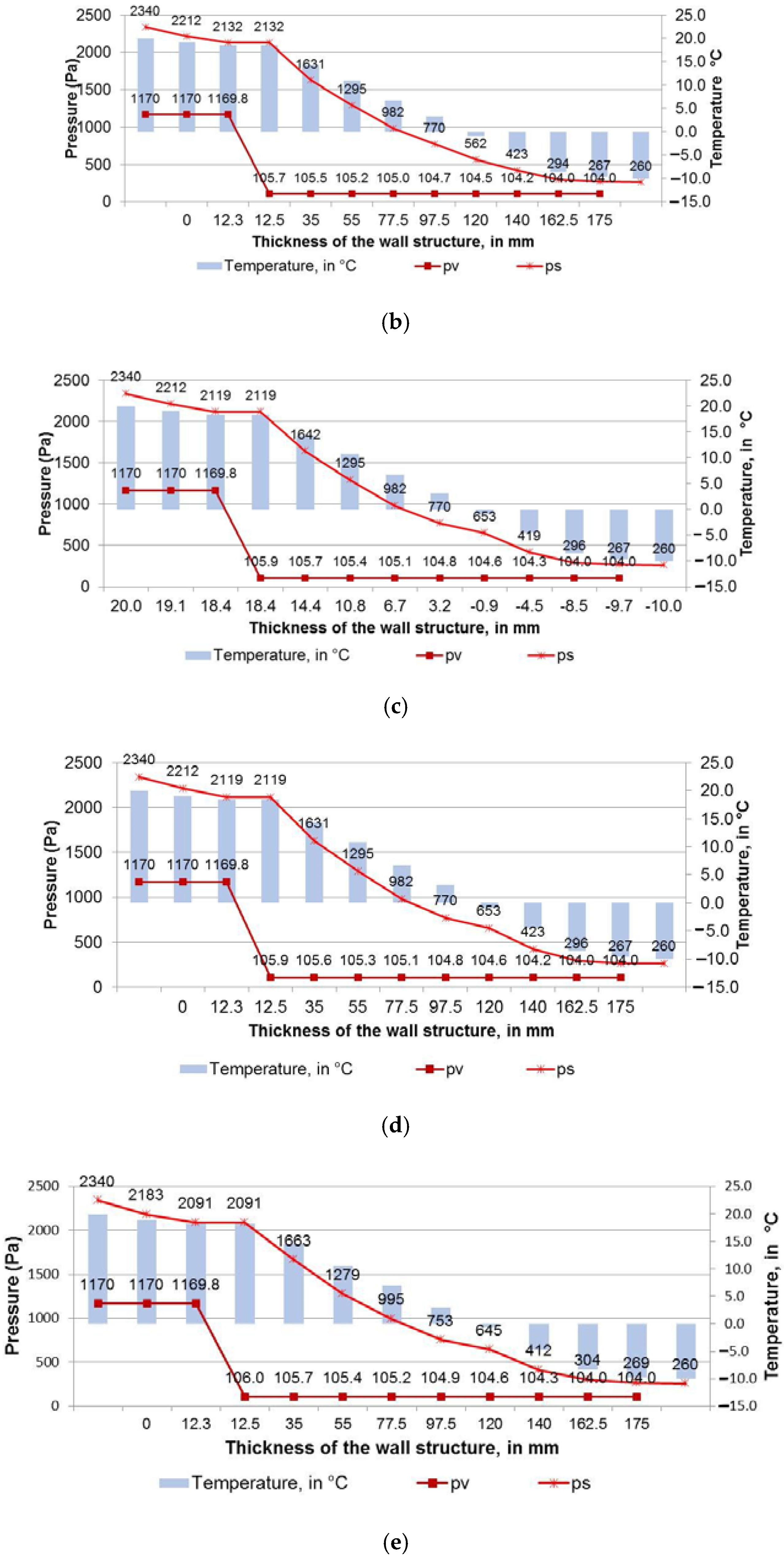
3.3. Vapour Transfer

The determination of the heat flux through a flat wall and of the vapour flux allows the determination of temperature variations, respectively of the vapour partial pressures on the thickness of each wall layer, variations that are in both cases linear. The heat flux through the wall was first calculated with Equation (2) for an indoor temperature (ti) of 20 °C, and outdoor temperature (te) of −10 °C. Following the calculations, the variation of the partial pressure (pv) and the saturation pressure (ps) were represented in the diagrams in Figure 8 for all investigated wall structures.
If intersections of the two curves are seen in the graphs, it indicates that the condensation occurs in that element, and if there is no intersection of the two pressure variation curves, this indicates that condensation is not present in the structure. As can be seen in Figure 8, there are no intersections for any of the investigated wall structures. This proves that the presence of condensation in the structures is not observed. In this way, the thermal insulation materials are less prone to degradation and they maintain their thermal properties in time. The same trend of the graphs from Figure 8 was highlighted by the simulation process with HT-flux software [43]. The simulation exhibited a great increase in vapour pressure on the side of the wall with the highest temperature and a linear decrease towards the side with the lowest temperature, no matter the type of the insulation material.

4. Conclusions

The thermal insulation performances of the exterior timber frame walls proposed in this study are in accordance with the criteria of passive houses issued by PHI [4] for the continental temperate zone, for which the recommended thermal transmittance (U) of the exterior walls ranges between 0.30 W/m2K and 0.50 W/m2K. All investigated structures in the present research recorded U-values from 0.20 W/m2K to 0.35 W/m2K, which resulted both from numerical method and in situ one. The experimental walls were tested in five configurations using three ABS-wool thermal insulated panels placed equidistantly inside the wall and fillers, such as wood fibers, ground paper, wool, ABS waste, and reed. The laboratory tests were conducting on HFM 436 Lambda Heat Flux Meter with set indoor and outdoor temperature conditions, and the resulting thermal resistance (R) values were used to calculate the thermal transmittance (U) values. The same experimental walls were subjected to in situ measurements using thermal flow and temperature sensors placed inside and outside the experimental wall, when differences between indoor and outdoor temperature were higher than 10 °C, corresponding to cold season. The calculated U values (Uc) were higher than those measured in situ conditions (Ui) for seven days, and those differences ranged between 7.64% (structure with ABS waste filler) and 56.3% (structure with wood fibers filler). These differences between Ui and Uc could be explained by erratic climate conditions for in situ measurements, accuracy of the sensors, and the type of fillers as regard to vapour diffusion (open or closed).
The natural resources and recycled wastes used in the structure of the proposed timber frame walls achieve the sustainability objective of the European Union policy and also contribute to the low carbon emissions and energy sustainability in this sector. As natural materials, the fillers used in this study also contribute to a healthy indoor environment, allowing the walls to “breathe”. The calculation of the variation of the partial pressure and of the saturation pressure proves that condensation is not present inside the five experimental structures.
Even if the structures of the external timber frame walls with wood fibers, wool, reed, and paper used as insulation materials are environmentally friendly and proven to have good thermal performances, which recommend them for passive houses, their hygroscopic properties and low anti-fungal and fire resistance limit their use without proper specific treatments, which were not the objective of the present research. Further research work can be focused on adjusting the structures of the walls investigated in this study for the cold climate, lowering the U-values below 0.15 W/m2K. This can be achieved by increasing the wall thickness or by modifying the interior structure of the wall.

Author Contributions

Conceptualization, S.-V.G. and C.C.; methodology, S.-V.G., D.Ș. and C.C.; software, S.-V.G.; validation, M.C., D.Ș. and C.C.; formal analysis, M.C.; investigation, S.-V.G.; resources, S.-V.G.; data curation, M.C.; writing—original draft preparation, S.-V.G.; writing—review and editing, C.C. and M.C.; visualization, M.C.; supervision, C.C.; project administration, S.-V.G. and C.C.; and funding acquisition, S.-V.G. All authors have read and agreed to the published version of the manuscript.

Funding

This research received no external funding.

Institutional Review Board Statement

Not applicable.

Informed Consent Statement

Not applicable.

Data Availability Statement

Not applicable.

Acknowledgments

We hereby acknowledge the structural funds project PRO-DD (POS-CCE, O.2.2.1., ID 123, SMIS 2637, No. 11/2009) for providing the infrastructure used in this work and the Contract No. 7/9.01.2014. The authors would like to thank the Transilvania University of Brasov for supporting the coverage of publication costs.

Conflicts of Interest

The authors declare no conflict of interest.

References

  1. European Commission. In Focus: Energy Efficiency in Buildings. Available online: https://ec.europa.eu/info/news/focus-energy-efficiency-buildings-2020-feb-17_en (accessed on 18 February 2022).
  2. European Commission. Energy Performance of Buildings Directive. Available online: https://energy.ec.europa.eu/topics/energy-efficiency/energy-efficient-buildings/energy-performance-buildings-directive_en (accessed on 18 February 2022).
  3. European Commission. A European Green Deal. Striving to Be the First Climate-Neutral Continent. Available online: https://ec.europa.eu/info/strategy/priorities-2019-2024/european-green-deal_en (accessed on 18 February 2022).
  4. Passive House Institute. Criteria for the Passive House, EnerPHit and PHI Low Energy Building Standard, Version 9f, Revised 15 August 2016. Available online: https://passiv.de/downloads/03_building_criteria_en.pdf (accessed on 19 February 2022).
  5. Miron, I.O.; Manea, D.L.; Mustea, A. Reed and Straw-Based Thermally Insulating Panels. ProEnvironment 2017, 9, 9–15. [Google Scholar]
  6. Doost-hoseini, K.; Taghiyari, H.R.; Elyasi, H.R. Correlation between sound absorption coefficients with physical and mechanical properties of insulation boards made from sugar cane bagasse. Compos. Part B 2014, 58, 10–15. [Google Scholar] [CrossRef]
  7. Ardente, F.; Beccali, M.; Cellura, M.; Mistretta, M. Building energy performance: A LCA case study of kenaf-fibres insulation board. Energy Build. 2008, 40, 1–10. [Google Scholar] [CrossRef]
  8. Luamkanchanaphan, T.; Chotikaprakhan, S.; Jarusombati, S. A study of physical, mechanical and thermal properties for thermal insulation from narrow-leaved cattail fibers. APCBEE Procedia 2012, 1, 46–52. [Google Scholar] [CrossRef] [Green Version]
  9. Pinto, J.; Paiva, A.; Varum, H.; Costa, A.; Cruz, D.; Pereira, S.; Fernandes, L.; Tavares, P.; Agarwal, J. Corn’s cob as a potential ecological thermal insulation material. Energy Build. 2011, 43, 1985–1990. [Google Scholar] [CrossRef]
  10. Zhou, X.; Zheng, F.; Li, H.; Lu, C. An environment-friendly thermal insulation material from cotton stalk fibers. Energy Build. 2010, 42, 1070–1074. [Google Scholar] [CrossRef]
  11. Agoudjil, B.; Benchabane, A.; Boudenne, A.; Ibos, L.; Fois, M. Renewable materials to reduce building heat loss: Characterization of date palm wood. Energy Build. 2011, 43, 491–497. [Google Scholar] [CrossRef]
  12. Evon, P.; Vandenbossche, V.; Pontailier, P.-Y.; Rigal, L. New thermal insulation fiberboards from cake generated during biorefinery of sunflower whole plant in a twin-screw extruder. Ind. Crop. Prod. 2014, 52, 354–362. [Google Scholar] [CrossRef] [Green Version]
  13. Kristak, L.; Ruziak, I.; Tudor, E.M.; Barbu, M.C.; Kain, G.; Reh, R. Thermophysical Properties of Larch Bark Composite Panels. Polymers 2021, 13, 2287. [Google Scholar] [CrossRef]
  14. Kjeldsen, A.; Price, M.; Lilley, C.; Guzniczak, E. A Review of Standards for Biodegradable Plastics, Industrial Biotechnology Innovation Centre. Technical Report. Industrial Biotechnology Innovation Centre. 2015. Available online: https://assets.publishing.service.gov.uk/government/uploads/system/uploads/attachment_data/file/817684/review-standards-for-biodegradable-plastics-IBioIC.pdf (accessed on 19 February 2022).
  15. Grigore, M.E. Methods of Recycling, Properties and Applications of Recycled Thermoplastic Polymers. Recycling 2017, 2, 24. [Google Scholar] [CrossRef] [Green Version]
  16. Hopewell, J.; Dvorak, R.; Kosior, E. Plastics recycling: Challenges and opportunities. Phil. Trans. R. Soc. B 2009, 364, 2115–2126. [Google Scholar] [CrossRef] [PubMed] [Green Version]
  17. Pérez, G.; Coma, J.; Martorell, I.; Cabeza, L.F. Vertical Greenery systems (VGS) for energy saving. Renew. Sust. Energy Rev. 2014, 39, 139–165. [Google Scholar] [CrossRef] [Green Version]
  18. Sheweka, S.M.; Mohamed, N.M. Green Facades as a New Sustainable Approach Towards Climate Change. Energy Procedia 2012, 18, 507–520. [Google Scholar] [CrossRef] [Green Version]
  19. Azkorra, Z.; Pérez, G.; Coma, J.; Cabeza, L.F.; Bures, S.; Álvaro; Erkoreka, A.; Urrestarazu, M. Evaluation of green walls as a passive acoustic insulation system for buildings. Appl. Acoust. 2015, 89, 46–56. [Google Scholar] [CrossRef] [Green Version]
  20. Miljan, M.; Miljan, M.J.; Miljan, J.; Akermann, K.; Karja, K. Thermal Transmittance of reed-insulated walls in a purpose-built test house. Mires Peat 2013, 13, 1–12. [Google Scholar]
  21. Miljan, M.; Miljan, J. Thermal Transmittance and the Embodied Energy of Timber Frame Lightweight Walls Insulated with Straw and Reed. IOP Conf. Ser. Mater. Sci. Eng. 2015, 96, 012076. [Google Scholar] [CrossRef] [Green Version]
  22. Simpson, A. The effect of moisture on the thermal property of a reed thatch roof during the UK heating season. Energy Build. 2022, 257, 111777. [Google Scholar] [CrossRef]
  23. Malheiro, R.; Ansolin, A.; Guarnier, C.; Fernandes, J.; Amorim, M.T.; Silva, S.M.; Mateus, R. The Potential of the Reed as a Regenerative Building Material—Characterisation of Its Durability, Physical, and Thermal Performances. Energies 2021, 14, 4276. [Google Scholar] [CrossRef]
  24. Kain, G.; Barbu, M.C.; Hinterreiter, S.; Richter, K.; Petutschnigg, A. Using Bark as a Heat Insulation Material. Bioresources 2013, 8, 3718–3731. [Google Scholar] [CrossRef]
  25. Ninikas, K.; Ntalos, G.; Hytiris, N.; Skarvelis, M. Thermal Properties of Insulation Boards Made of Tree Bark & Hemp Residues. J. Sustain. Archit. Civ. Eng. 2019, 24, 71–77. [Google Scholar]
  26. Kain, G.; Tudor, E.M.; Barbu, M.C. Bark Thermal Insulation Panels: An Explorative Study on the Effects of Bark Species. Polymers 2020, 12, 2140. [Google Scholar] [CrossRef] [PubMed]
  27. Euring, M.; Kirsch, A.; Kharazipour, A. Hot-Air/Hot-Steam Process for the Production of Laccase-Mediator-System Bound Wood Fiber Insulation Boards. Bioresources 2015, 10, 3541–3552. [Google Scholar] [CrossRef] [Green Version]
  28. Gößwald, J.; Barbu, M.C.; Petutschnigg, A.; Tudor, E.M. Binderless Thermal Insulation Panels Made of Spruce Bark Fibres. Polymers 2021, 13, 1779. [Google Scholar] [CrossRef] [PubMed]
  29. Akcagun, E.; Boguslawska-Baczek, M.; Hes, L. Thermal insulation and thermal contact properties of wool and wool/PES fabrics in wet state. J. Nat. Fibers 2019, 16, 199–208. [Google Scholar] [CrossRef]
  30. Patnaik, A.; Mvubu, M.; Muniyasamy, S.; Botha, A. Thermal and sound insulation materials from waste wool and recycled polyester fibers and their biodegradation studies. Energy Build. 2015, 92, 161–169. [Google Scholar] [CrossRef]
  31. Pennacchio, R.; Savio, L.; Bosia, D.; Thiebat, F.; Piccablotto, G.; Patrucco, A.; Fantucci, S. Fitness: Sheep-wool and hemp sustainable insulation panels. Energy Procedia 2017, 111, 287–297. [Google Scholar] [CrossRef]
  32. Zach, J.; Korjenic, A.; Petranek, V.; Hroudova, J.; Bednar, T. Performance evaluation and research of alternative thermal insulation based on sheep wool. Energy Build. 2012, 49, 246–253. [Google Scholar] [CrossRef]
  33. Moreno-Rangel, A.; Tsekleves, E.; Vazquez, J.M.; Schmetterer, T. The Little Book of Bio-Based Fibre Materials in Passivhaus Construction in Latin America; Lancaster University: Lancaster, UK, 2021; pp. 15–16. [Google Scholar]
  34. Panyakaev, S.; Fotios, S. 321: Agricultural Waste Materials as Thermal insulation Dwellings in Thailand: Preliminary Results. In Proceedings of the 25th Conference on Passive and Low Energy Architecture, Dublin, Ireland, 22–24 October 2008. [Google Scholar]
  35. Korjenic, A.; Petranek, V.; Zach, J.; Hroudova, J. Development and performance evaluation of natural thermal-insulation materials composed of renewable resources. Energy Build. 2011, 43, 2518–2523. [Google Scholar] [CrossRef]
  36. Ninikas, K.; Mitani, A.; Koutsianitis, D.; Ntalos, G.; Taghiyari, H.R.; Papadopoulos, A.N. Thermal and Mechanical Properties of Green Insulation Composites Made from Cannabis and Bark Residues. J. Compos. Sci. 2021, 5, 132. [Google Scholar] [CrossRef]
  37. Asdrubali, F.; D’Alessandro, F.; Schiavoni, S. A review of unconventional sustainable building insulation materials. SM&T 2015, 4, 1–17. [Google Scholar]
  38. Zhang, S.Y.; Li, Y.Y.; Wang, C.G.; Wang, X. Thermal Insulation Boards from Bamboo Paper Sludge. Bioresources 2017, 12, 56–67. [Google Scholar] [CrossRef] [Green Version]
  39. Zhang, L.; Luo, X.; Meng, X.; Wang, Y.; Hou, C.; Long, E. Effect of the thermal insulation layer location on wall dynamic thermal response rate under the air-conditioning intermittent operation. Case Stud. Therm. Eng. 2017, 10, 79–85. [Google Scholar] [CrossRef]
  40. Garay, R.; Arregi, B.; Elguezabal, P. Experimental Thermal Performance Assessment of a Prefabricated External Insulation System for Building Retrofitting. Procedia Environ. Sci. 2017, 38, 155–161. [Google Scholar] [CrossRef] [Green Version]
  41. Escudero, C.; Martin, K.; Erkoreka, A.; Flores, I.; Sala, J.M. Experimental thermal characterization of radiant barriers for building insulation. Energy Build. 2013, 59, 62–72. [Google Scholar] [CrossRef]
  42. Susurova, I.; Angulo, M.; Bahrami, P.; Stephens, B. A model of vegetated exterior facades for evaluation of wall thermal performance. Build. Environ. 2013, 67, 1–13. [Google Scholar] [CrossRef]
  43. Ninikas, K.; Tallaros, P.; Mitani, A.; Koutsianitis, D.; Ntalos, G.; Taghiyari, H.R.; Papadopoulos, A.N. Thermal Behavior of a Light Timber-Frame Wall vs. a Theoretical Simulation with Various Insulation Materials. J. Compos. Sci. 2022, 6, 22. [Google Scholar] [CrossRef]
  44. Iejavs, J.; Rozins, R. Water Vapour Permeability Properties of Cellular Wood Material and Condensation Risk of Composite Panel Walls. Pro Ligno 2016, 12, 3–11. [Google Scholar]
  45. Gullbrekken, L.; Geving, S.; Time, B.; Andresen, I. Moisture conditions in passive house wall constructions. Energy Procedia 2015, 78, 219–224. [Google Scholar] [CrossRef] [Green Version]
  46. Morelli, M.; Rasmussen, T.V.; Therkelsen, M. Exterior Wood-Frame Walls—Wind–Vapour Barrier Ratio in Denmark. Buildings 2021, 11, 428. [Google Scholar] [CrossRef]
  47. Janssen, H.; Blocken, B.; Carmeliet, J. Conservative modelling of the moisture and heat transfer in building components under atmospheric excitation. Int. J. Heat Mass Transf. 2007, 50, 1128–1140. [Google Scholar] [CrossRef] [Green Version]
  48. Labat, M.; Woloszyn, M.; Garnier, G.; Roux, J.J. Dynamic coupling between vapour and heat transfer in wall assemblies: Analysis of measurements achieved under real climate. Build. Environ. 2015, 87, 129–141. [Google Scholar] [CrossRef]
  49. Wang, H.; Chiang, P.C.; Cai, Y.; Li, C.; Wang, X.; Chen, T.S.; Wei, S.; Huang, Q. Application of Wall and Insulation Materials on Green Building: A Review. Sustainability 2018, 10, 3331. [Google Scholar] [CrossRef] [Green Version]
  50. ISO 8301:1991; Thermal Insulation—Determination of Steady-State Thermal Resistance and Related Properties—Heat Flow Meter Apparatus. International Organization for Standardization: Geneva, Switzerland, 1991.
  51. DIN EN 12667:2001; Thermal Performance of Building Materials and Products—Determination of Thermal Resistance by Means of Guarded Hot Plate and Heat Flow Meter Methods—Products of High and Medium Thermal Resistance, European Standard, English Version. Deutsches Institut fur Normung: Berlin, Germany, 2001.
  52. ISO 6946:2017; Building Components and Building Elements—Thermal Resistance and Thermal Transmittance—Calculation Methods. International Organization for Standardization: Geneva, Switzerland, 2017.
  53. Geving, S.; Lunde, E.; Holme, J. Laboratory investigations of moisture conditions in wood frame walls with wood fiber insulation. In Proceedings of the 6th International Building Physics Conference (IBPC), Torino, Italy, 14–17 June 2015; pp. 1455–1460. [Google Scholar]
  54. Asdrubali, F.; D’Alessandro, F.; Baldinelli, G.; Bianchi, F. Evaluating in situ thermal transmittance of green buildings masonries—A case study. Case Stud. Constr. Mater. 2014, 1, 53–59. [Google Scholar] [CrossRef]
  55. Durica, P.; Juras, P.; Gaspierik, V.; Rybarik, J. Long-term Monitoring of Thermo-technical Properties of Lightweight Constructions of External Walls Being Exposed to the Real Conditions. Procedia Eng. 2015, 111, 176–182. [Google Scholar] [CrossRef] [Green Version]
  56. Rafidiarison, H.; Mougel, E.; Nicolas, A. Laboratory Experiments on Hygrothermal Behaviour of Real-Scale Timber Walls. Maderas-Cienc. Tecnol. 2012, 14, 389–401. [Google Scholar] [CrossRef] [Green Version]
Figure 1. ABS-wool panel formation: (a) ABS (60%) and wool (40%) prepared to be mixed; (b) Mat formation in wooden frame; (c) Panel after sizing to the final dimensions.
Forests 13 00522 g001
Figure 2. The structure of the timber frame wall: 1—gypsum board; 2—aluminum foil; 3—fillers; 4—ABS-wool composites; 5—particleboard; 6—OSB.
Forests 13 00522 g002
Figure 3. In situ experimental test: (a) Positioning of the experimental wall (W); (b) Placement of the sensors on the structure.
Forests 13 00522 g003
Figure 4. In situ measurements diagrams of thermal transmittance of the structures with the following fillers: (a) wood fibers; (b) ground paper; (c) wool; (d) ABS waste; (e) reed.
Forests 13 00522 g004
Figure 5. In situ measured thermal transmittance (U) values for the experimental wall structures.
Forests 13 00522 g005
Figure 6. Comparison between thermal resistance values of investigated wall structures in the conditions of cold and warm season simulation, for different fillers.
Forests 13 00522 g006
Figure 7. Mean values of thermal transmittance for the entire test cycle.
Forests 13 00522 g007
Figure 8. Graphic example of the variation of the partial pressure (pv) and the saturation pressure (ps) for the experimental structures with the following fillers: (a) wood fibers; (b) ground paper; (c) wool; (d) ABS waste; (e) reed.
Forests 13 00522 g008aForests 13 00522 g008b
Table 1. Density and thermal conductivity coefficient of the insulation materials.
Type of MaterialDensity, in kg/m3Thermal Conductivity Coefficient, λ, in W/mK
Wool (W)23.30.0424
Paper (P)56.10.0338
Wood fibers (WF)66.00.0391
ABS77.60.0410
Reed (R)79.40.0524
ABS-Wool composite (ABS-W)3000.0420
Table 2. Experimental design of the wall structures.
Wall CodeGB
(pcs.)
Fillers (no. of Layers)ABS-W
(pcs.)
OSB
(pcs.)
ABSWoolPaperWood FiberReed
W114 31
W21 4 31
W31 4 31
W41 4 31
W51 431
Table 3. Temperature configuration setup.
Test NumberT1, in °C
for Bottom Plate
T2, in °C
for Top Plate
ΔT = T2 − T1 in °CMean Temperature (T1 + T2)/2
1−1020305
2−520257.5
30202010
45201512.5
510201015
61520517.5
Publisher’s Note: MDPI stays neutral with regard to jurisdictional claims in published maps and institutional affiliations.

