
Effect of Heat Treatment on the Microstructure and Mechanical Properties of Rotary Friction Welded AA7075 and AA5083 Dissimilar Joint
 , , and
Abstract
:1. Introduction
2. Experimental Procedure
2.1. Base Metal
2.2. Heat Treatments
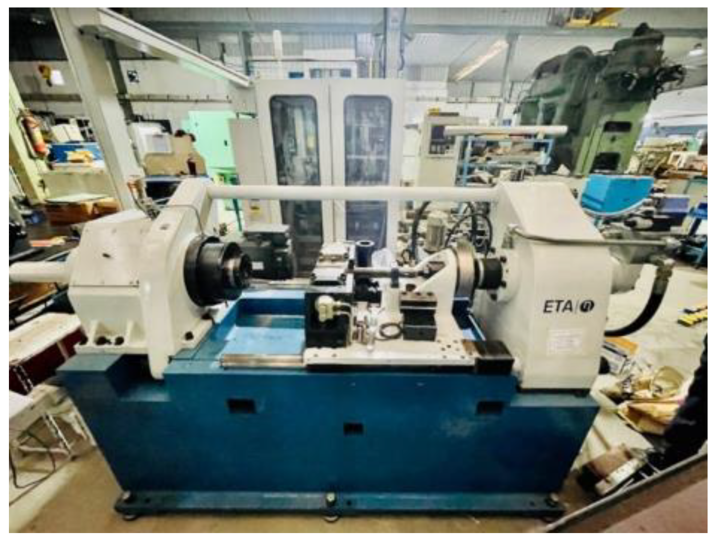
2.3. Welding Details
2.4. Metallographic Examination
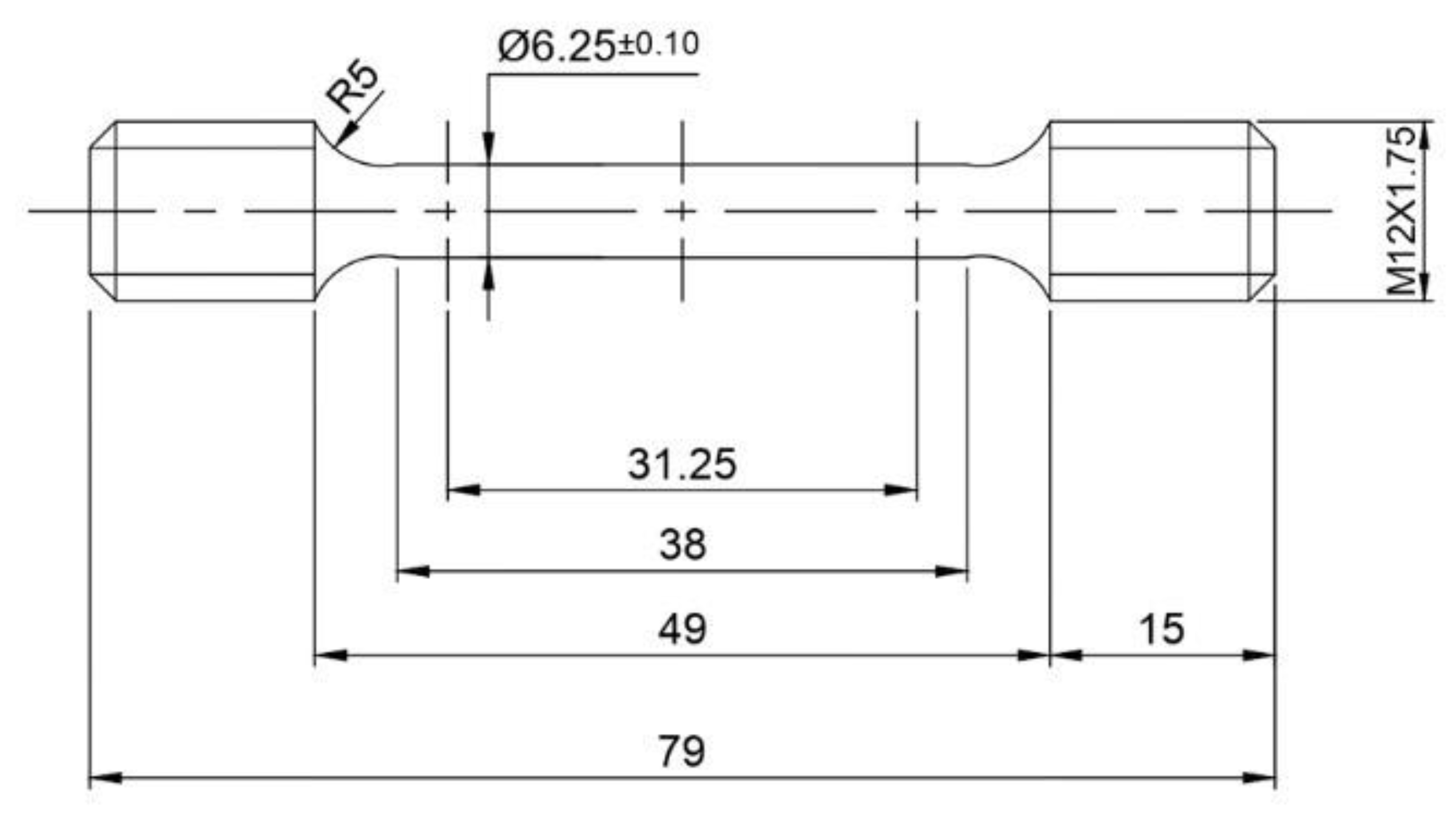
2.5. Mechanical Testing
3. Results and Discussion
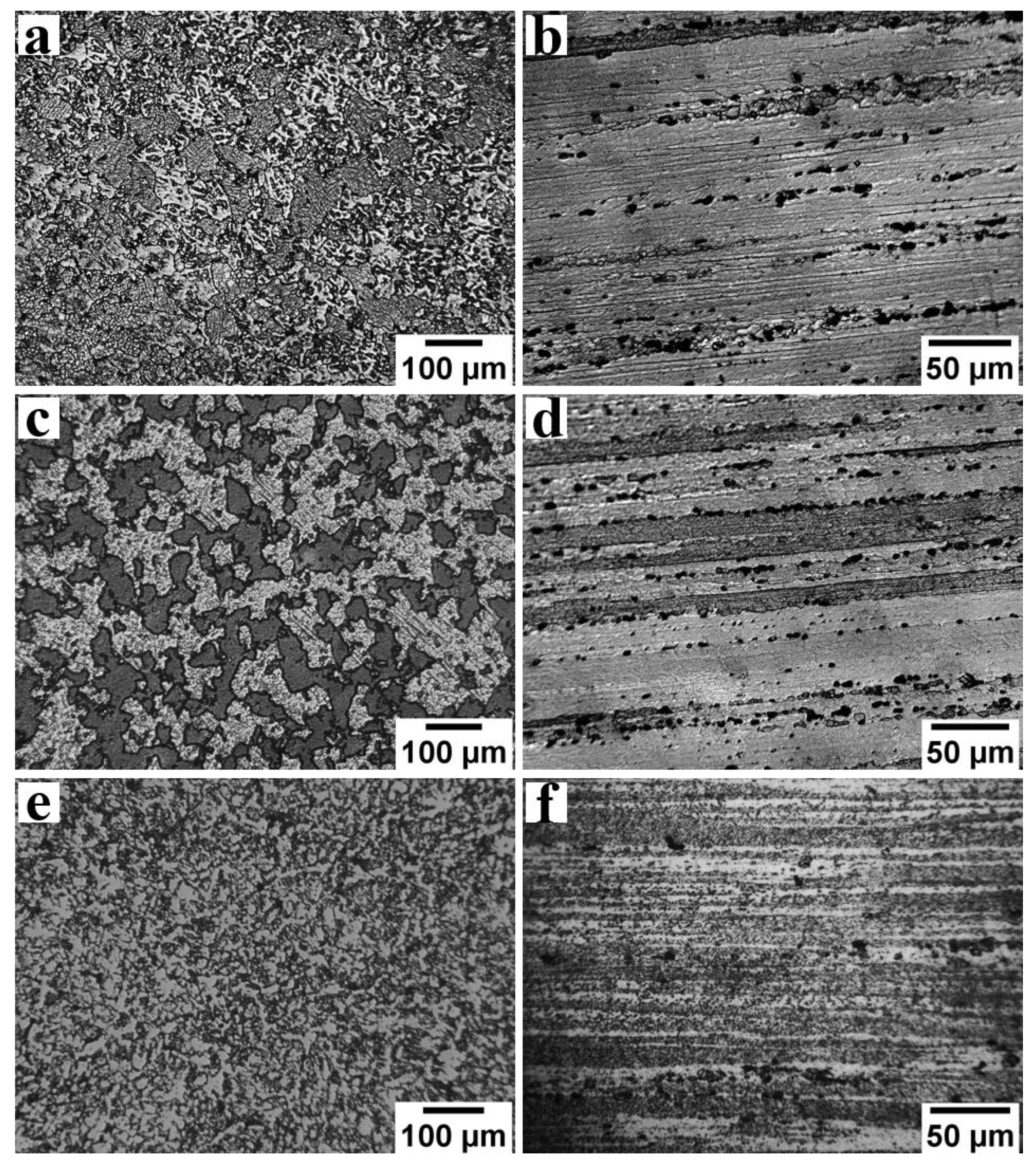
3.1. Microstructure: Base/Parent Metal
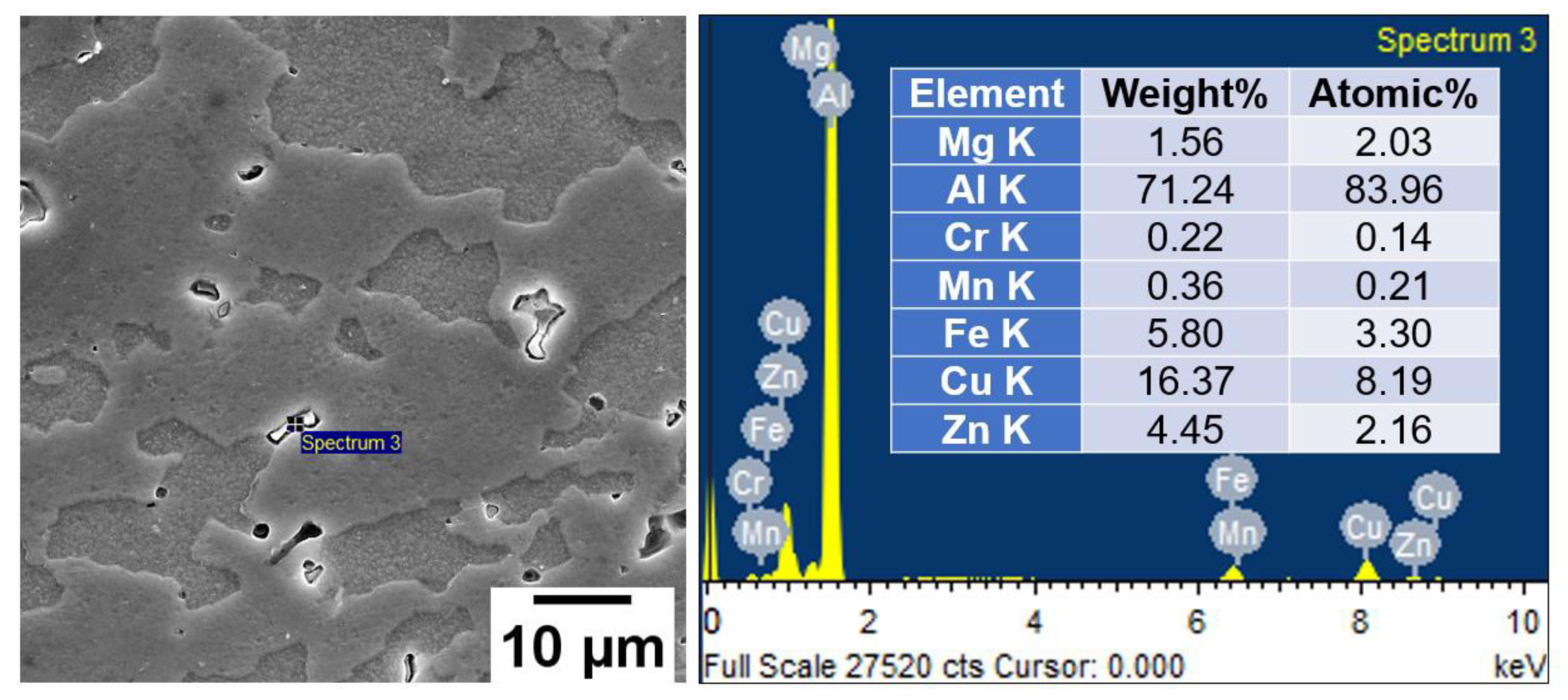
3.2. Microstructure: Weldment
3.3. Mechanical Properties
4. Conclusions
- Defect-free dissimilar AA5083/AA7075 welds, such as cracks or porosity, could be obtained with a rotary friction welding technique.
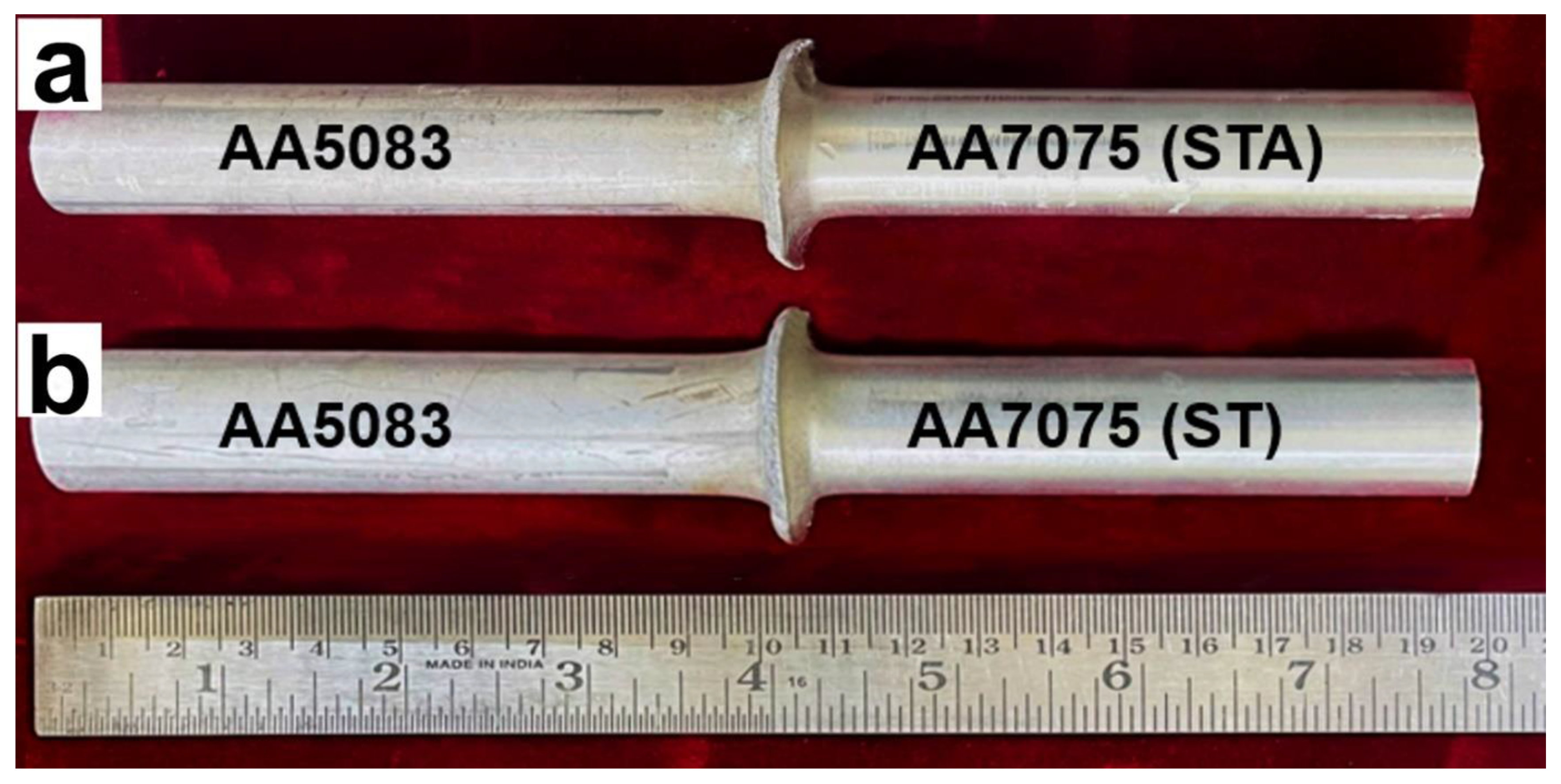
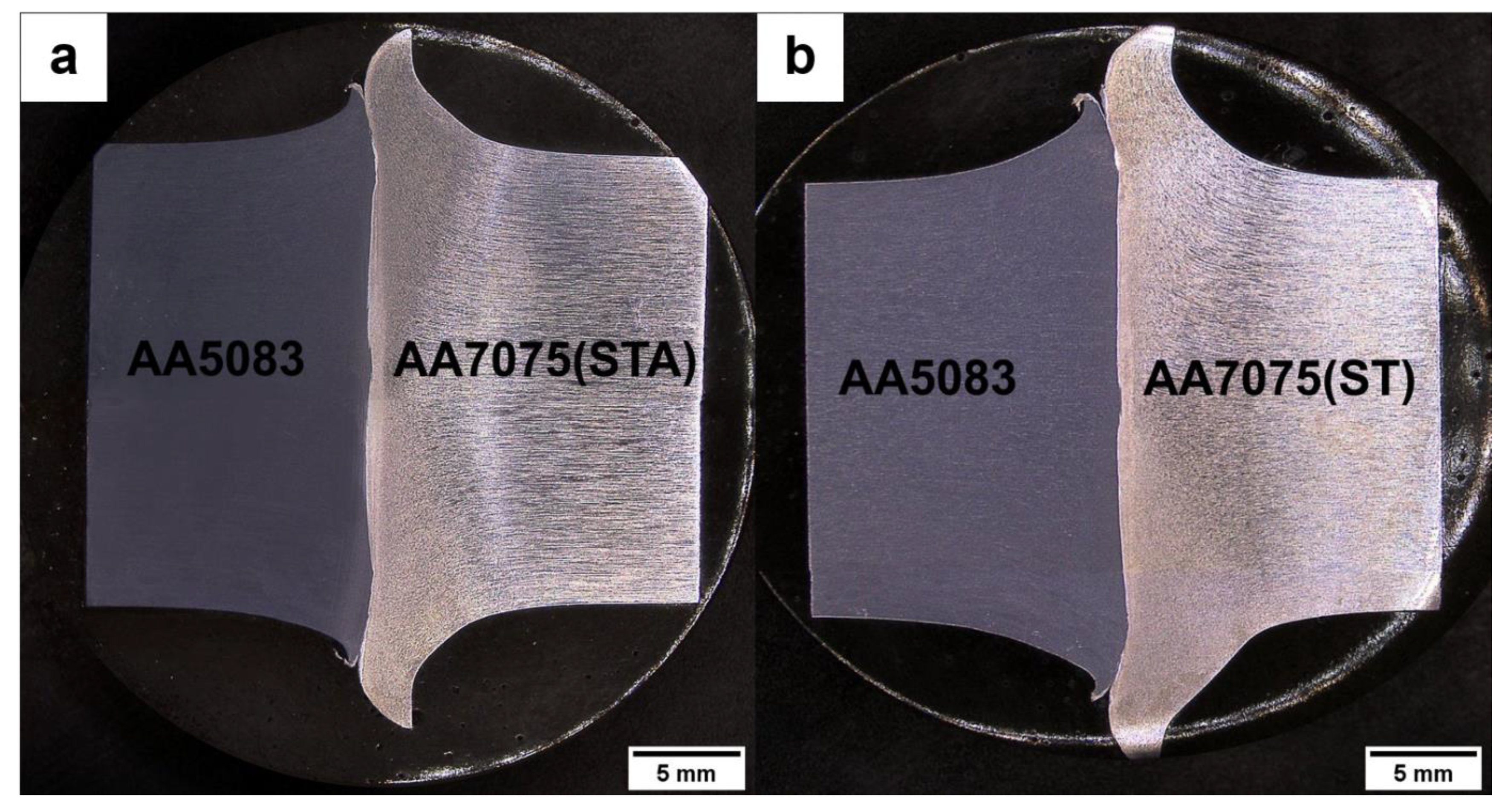
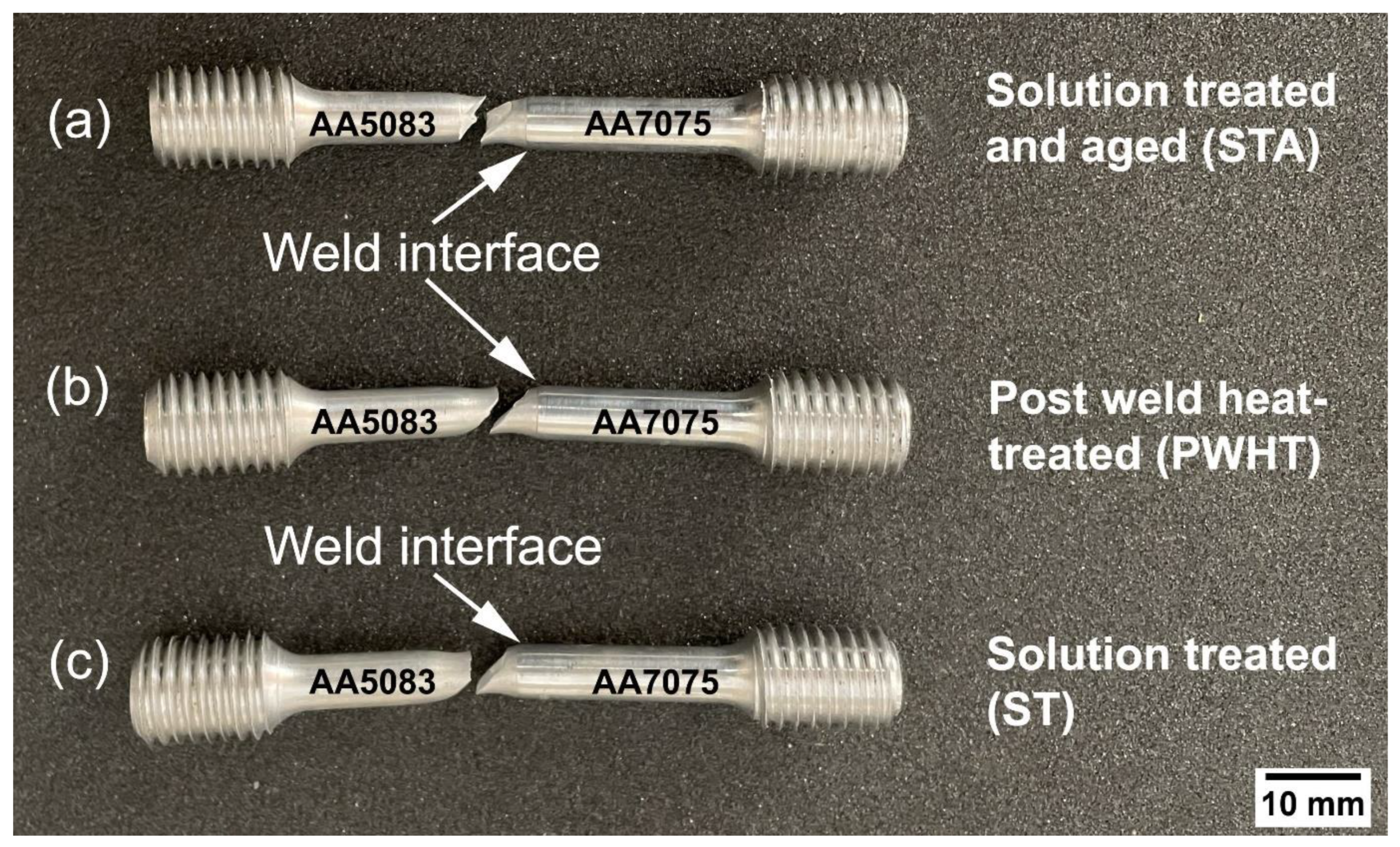
- The macrostructure of dissimilar AA5083/AA7075 welds displayed more flash on the AA7075 side, and little flash on the AA5083 side, and this can be attributed to AA7075 having a lower melting point and higher softening at friction welding temperatures.
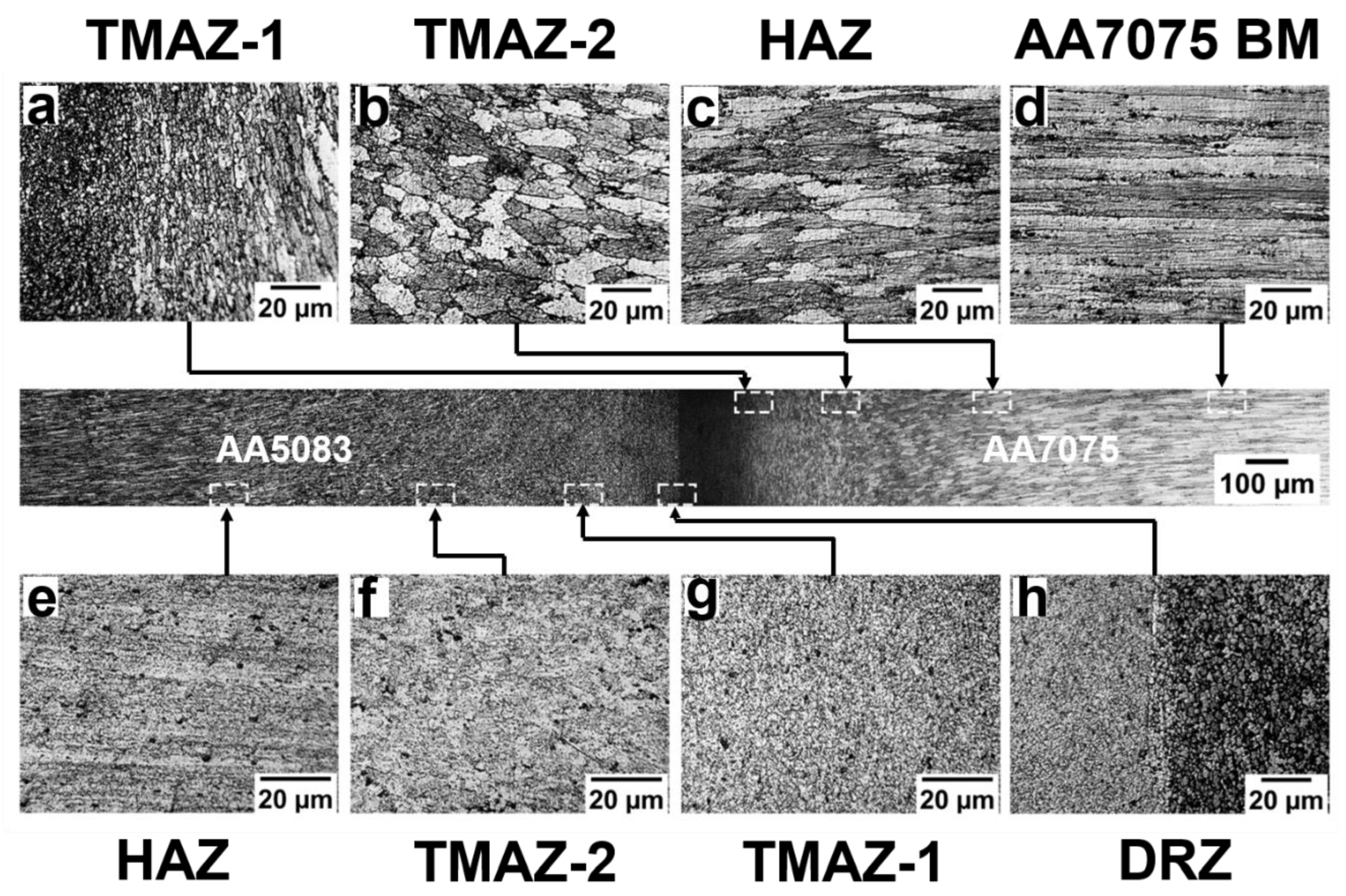
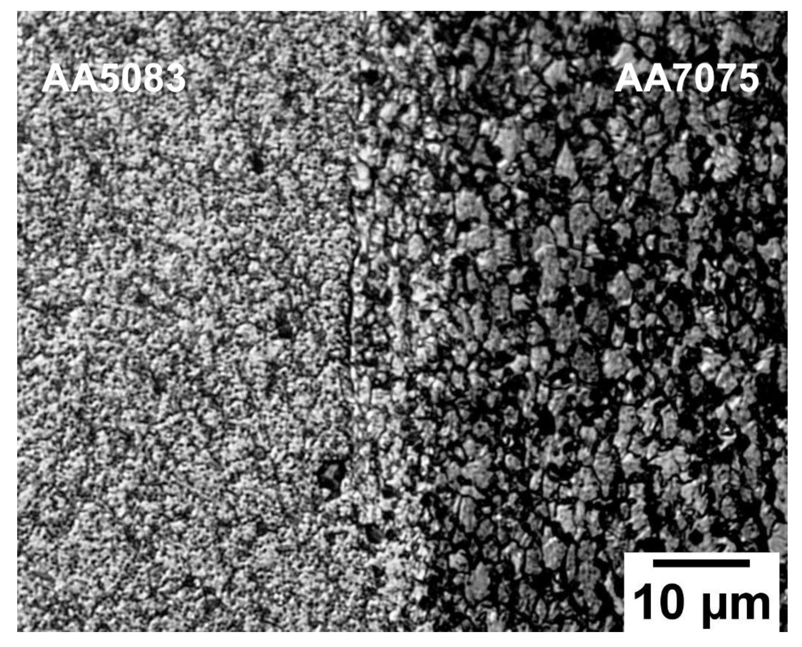
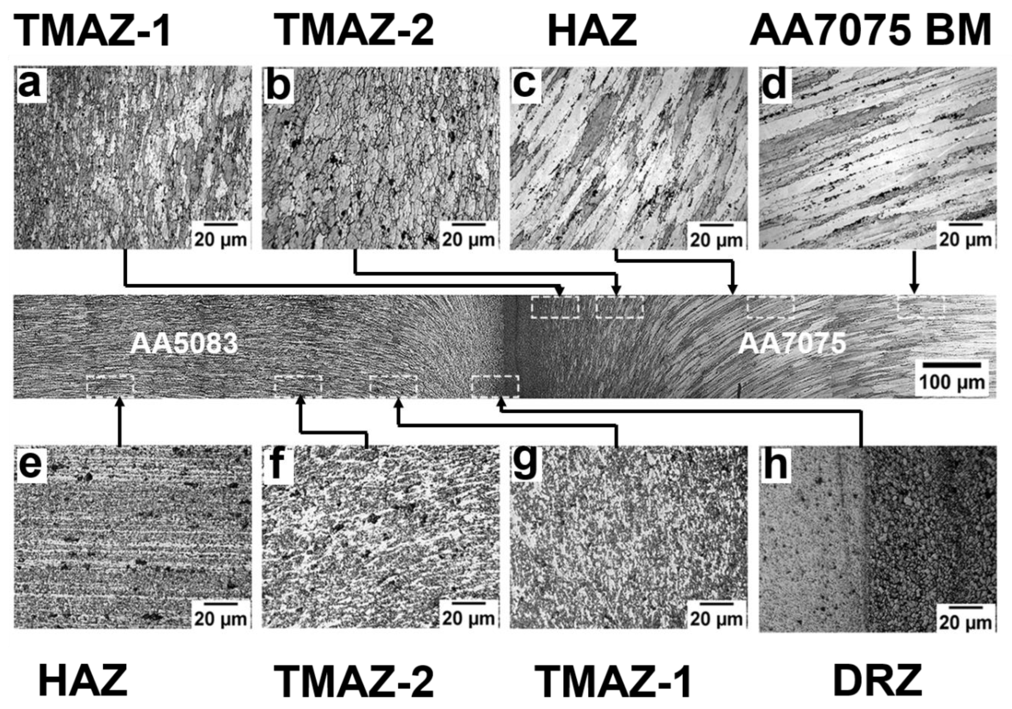
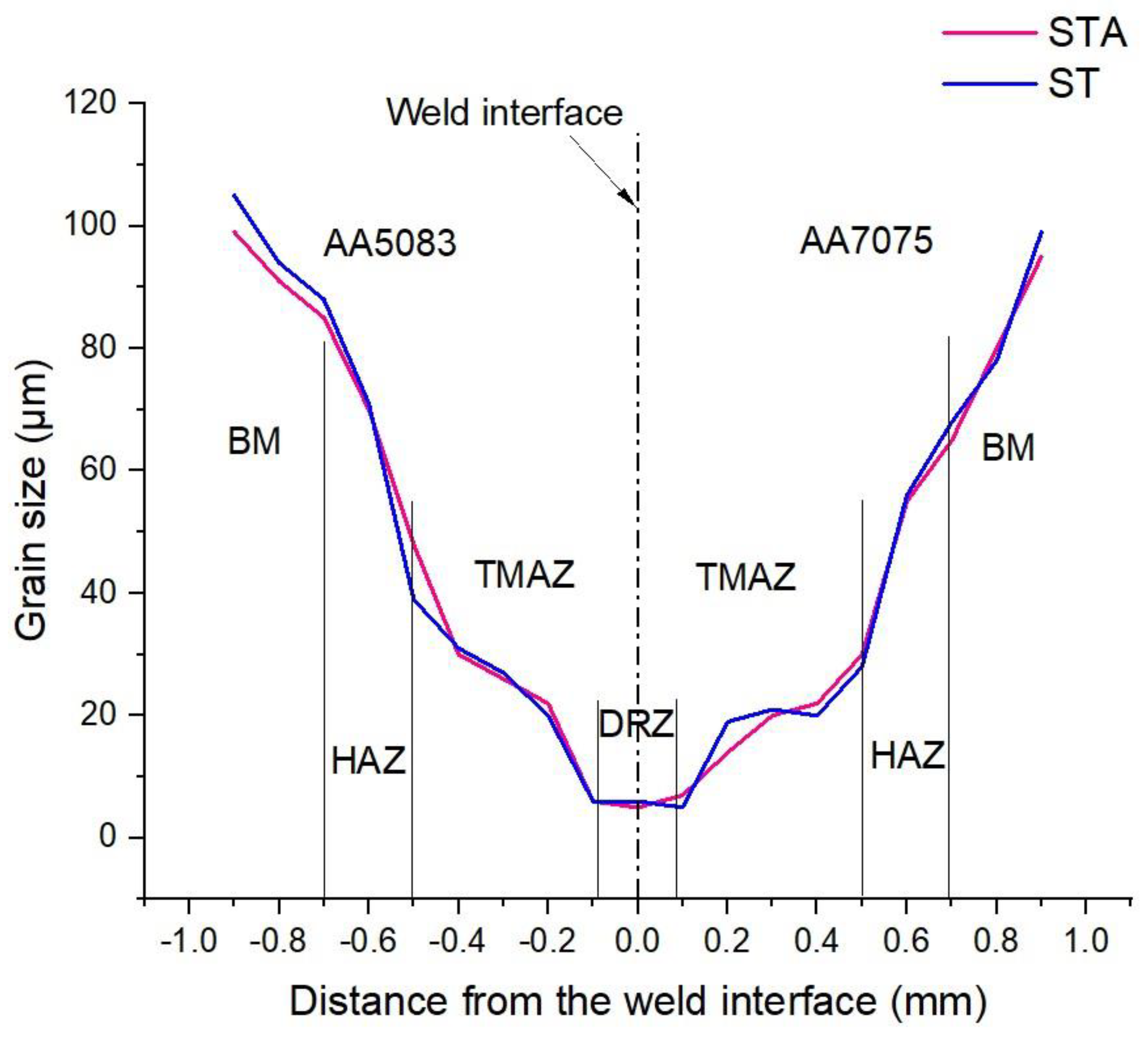
- Significant grain refinement was observed at the weld interface (DRZ) due to the continuous dynamic recrystallization occurring during rotary friction welding. The region next to DRZ experienced lower strain and high temperatures, resulting in the formation of deformed grains in the TMAZ.
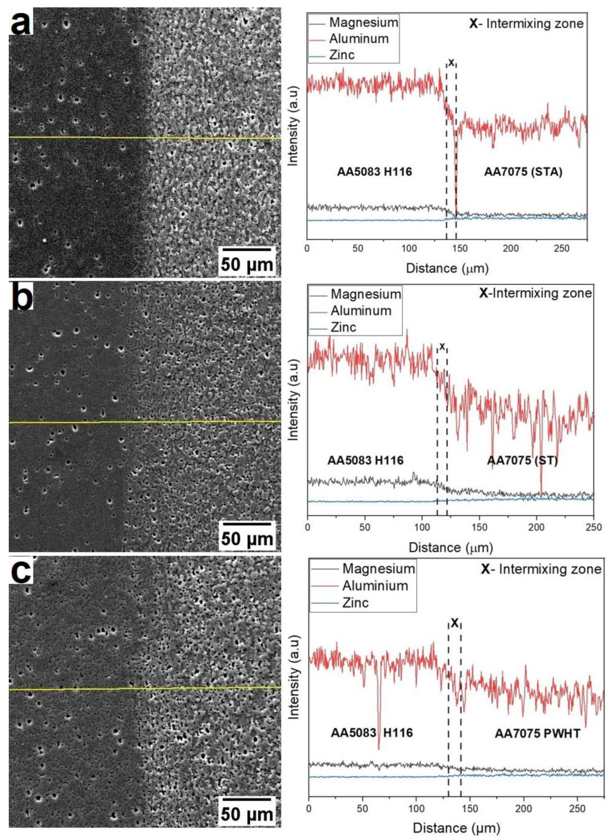
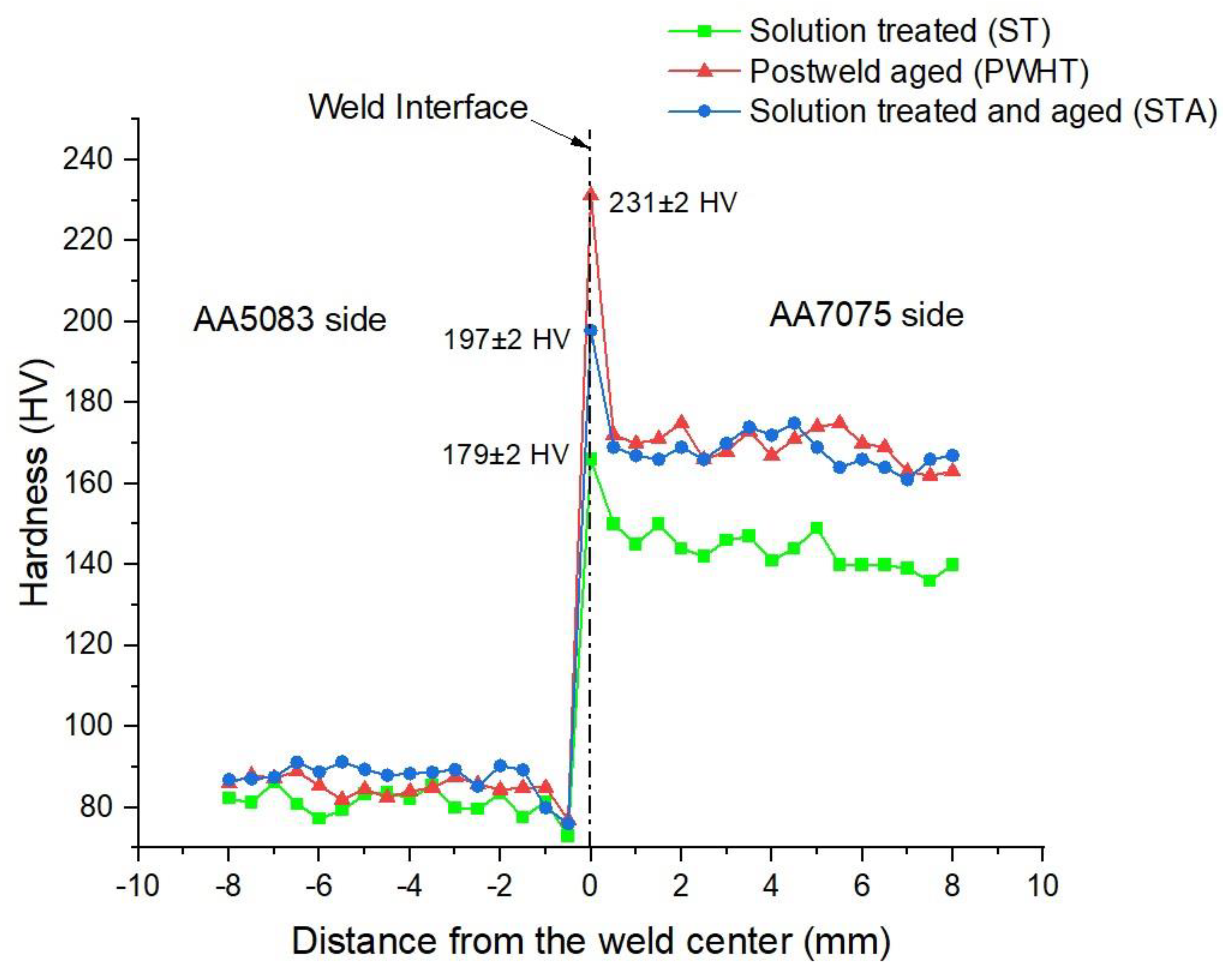
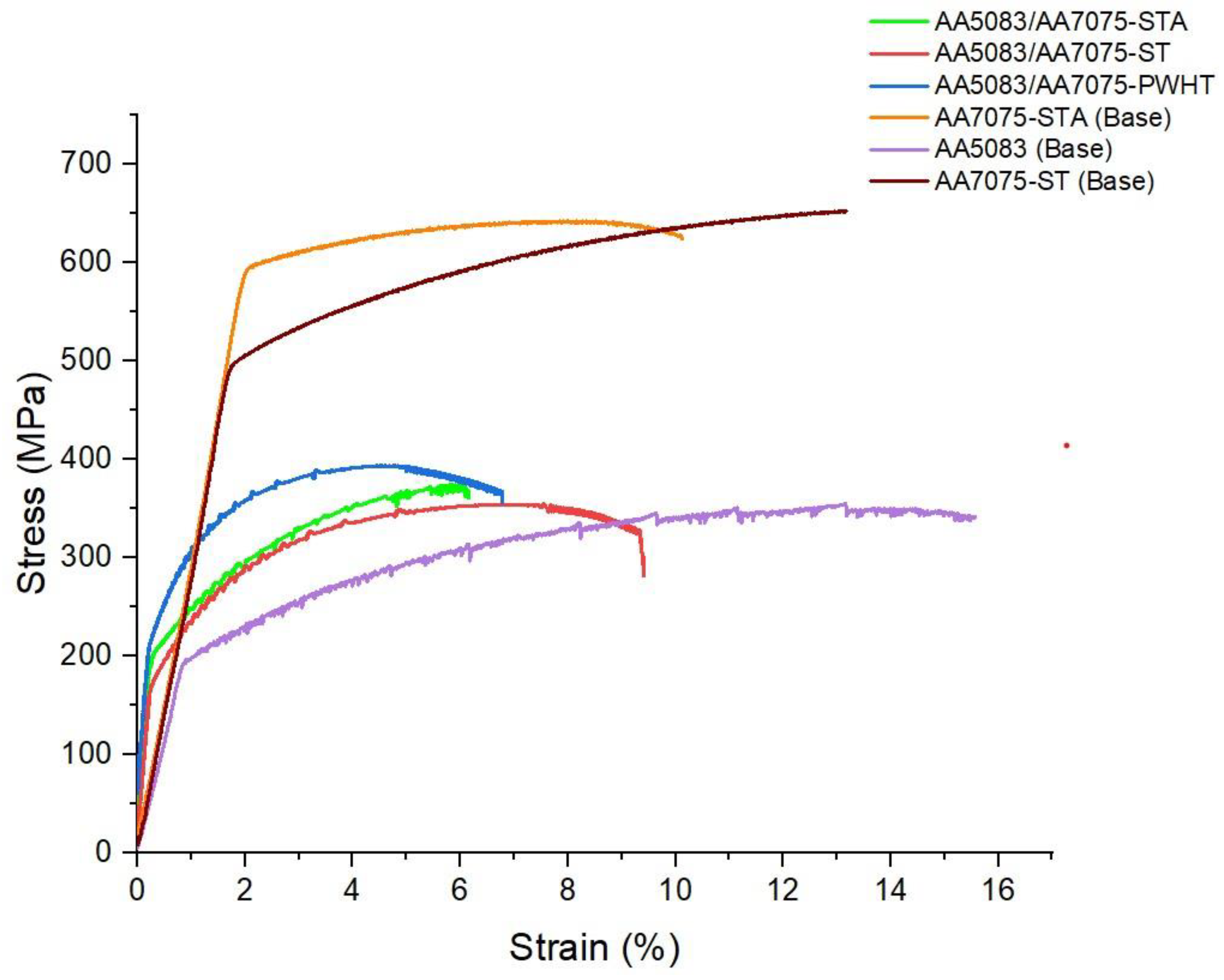
- The rotary friction welded sample AA5083/AA7075-PWHT joint exhibited the highest strength (YS: 195 ± 3 MPa, UTS: 387 ± 2 MPa) among all the other welded conditions, and this may be attributed to the major strengthening precipitates MgZn2 (of AA7075) formed during postweld aging. On the contrary, the partial dissolution of these precipitates during welding resulted in higher strength and low ductility of AA5083/AA7075-STA welds (YS: 190 ± 2 MPa, UTS: 360 ± 4 MPa and % elongation: 6 ± 1) compared to AA5083/AA7075-ST welds (YS: 178 ± 6 MPa, UTS: 345 ± 5 MPa and % elongation: 9 ± 2).
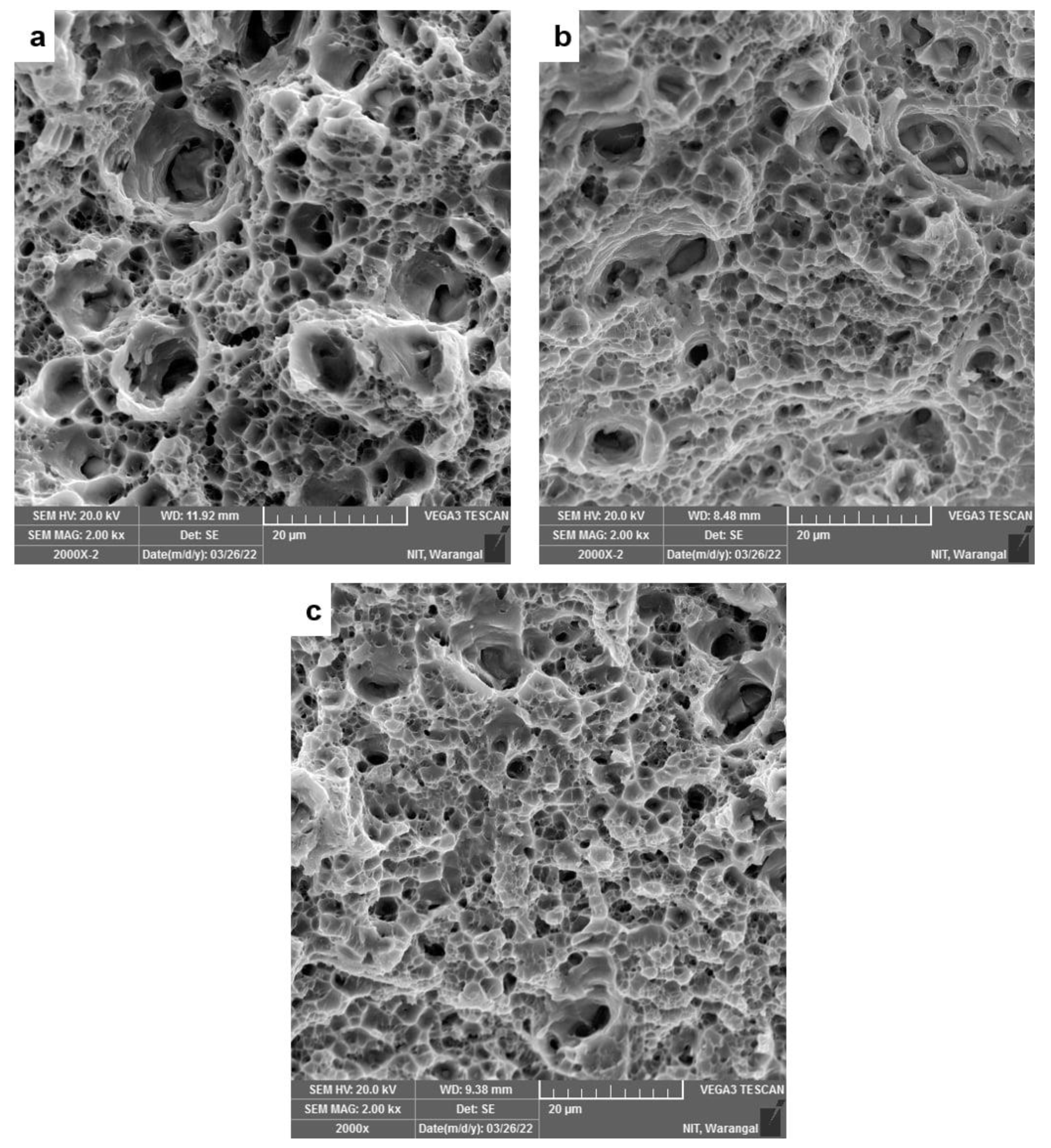
- All dissimilar welds failed in the HAZ region of the AA5083 side due to the formation of coarse grains, indicating the weakest region.
Author Contributions
Funding
Institutional Review Board Statement
Informed Consent Statement
Data Availability Statement
Acknowledgments
Conflicts of Interest
References
- Cevik, B. Gas Tungsten Arc Welding of 7075 Aluminum Alloy: Microstructure Properties, Impact Strength, and Weld Defects. Mater. Res. Express 2018, 5, 066540. [Google Scholar] [CrossRef]
- Mathers, G. The Welding of Aluminium and Its Alloys; Woodhead Publishing Ltd.: Cambridge, MA, USA, 2002. [Google Scholar]
- Su, J.Q.; Nelson, T.W.; Mishra, R.; Mahoney, M. Microstructural Investigation of Friction Stir Welded 7050-T651 Aluminium. Acta Mater. 2003, 51, 713–729. [Google Scholar] [CrossRef]
- Barnes, T.A.; Pashby, I.R. Joining Techniques for Aluminum Spaceframes Used in Automobiles. Part II-Adhesive Bonding and Mechanical Fasteners. J. Mater. Process. Technol. 2000, 99, 72–79. [Google Scholar] [CrossRef]
- Khan, N.Z.; Siddiquee, A.N.; Khan, Z.A. Friction Stir Welding Dissimilar Aluminum Alloys; CRC Press: Boca Raton, FL, USA, 2017; Volume 7, ISBN 9781138196759. [Google Scholar]
- Meshram, S.D.; Madhusudhan Reddy, G. Friction Welding of AA6061 to AISI 4340 Using Silver Interlayer. Def. Technol. 2015, 11, 292–298. [Google Scholar] [CrossRef] [Green Version]
- Coniglio, N.; Cross, C.E. Initiation and growth mechanisms for weld solidification cracking. Int. Mater. Rev. 2013, 58, 375–397. [Google Scholar] [CrossRef]
- Kah, P.; Rajan, R.; Martikainen, J.; Suoranta, R. Investigation of Weld Defects in Friction-Stir Welding and Fusion Welding of Aluminium Alloys. Int. J. Mech. Mater. Eng. 2015, 10, 1–10. [Google Scholar] [CrossRef] [Green Version]
- Rendigs, K.H. Aluminium Structures Used in Aerospace-Status and Prospects. Mater. Sci. Forum 1997, 242, 11–24. [Google Scholar] [CrossRef]
- Li, X.; Li, J.; Liao, Z.; Jin, F.; Xiong, J.; Zhang, F. Effect of Rotation Speed on Friction Behavior and Radially Non-Uniform Local Mechanical Properties of AA6061-T6 Rotary Friction Welded Joint. J. Adhes. Sci. Technol. 2018, 32, 1987–2006. [Google Scholar] [CrossRef]
- Ashfaq, M.; Rao, K.J. Comparing Bond Formation Mechanism between Similar and Dissimilar Aluminium Alloy Friction Welds. Mater. Sci. Technol. 2014, 30, 329–338. [Google Scholar] [CrossRef]
- Rao, T.S.; Reddy, G.M.; Rao, S.R.K. Microstructure and Mechanical Properties of Friction Stir Welded AA7075-T651 Aluminum Alloy Thick Plates. Trans. Nonferrous Met. Soc. China (Engl. Ed.) 2015, 25, 1770–1778. [Google Scholar] [CrossRef]
- Meng, X.; Huang, Y.; Cao, J.; Shen, J.; dos Santos, J.F. Recent Progress on Control Strategies for Inherent Issues in Friction Stir Welding. Prog. Mater. Sci. 2021, 115, 100706. [Google Scholar] [CrossRef]
- Elumalai, B.; Omsakthivel, U.; Yuvaraj, G.; Giridharan, K.; Vijayanand, M.S. Optimization of Friction Welding Parameters on Aluminium 7068 Alloy. Mater. Today Proc. 2021, 45, 1919–1923. [Google Scholar] [CrossRef]
- Chainarong, S.; Meengam, C.; Tehyo, M. Rotary Friction Welding of Dissimilar Joints between SSM356 and SSM6061 Aluminium Alloys Produced by GISS. Eng. J. 2017, 21, 181–191. [Google Scholar] [CrossRef] [Green Version]
- Fukumoto, S.; Tsubakino, H.; Okita, K.; Aritoshi, M.; Tomita, T. Amorphization by Friction Welding between 5052 Aluminum Alloy and 304 Stainless Steel. Scr. Mater. 2000, 42, 807–812. [Google Scholar] [CrossRef]
- Kumar, P.V.; Reddy, G.M.; Rao, K.S. Microstructure, Mechanical and Corrosion Behavior of High Strength AA7075 Aluminium Alloy Friction Stir Welds–Effect of Post Weld Heat Treatment. Def. Technol. 2015, 11, 362–369. [Google Scholar] [CrossRef] [Green Version]
- Priya, R.; Subramanya Sarma, V.; Prasad Rao, K. Effect of Post Weld Heat Treatment on the Microstructure and Tensile Properties of Dissimilar Friction Stir Welded AA 2219 and AA 6061 Alloys. Trans. Indian Inst. Met. 2009, 62, 11–19. [Google Scholar] [CrossRef]
- Sasmito, A.; Ilman, M.N.; Iswanto, P.T.; Muslih, R. Effect of Rotational Speed on Static and Fatigue Properties of Rotary Friction Welded Dissimilar AA7075/AA5083 Aluminium Alloy Joints. Metals 2022, 12, 99. [Google Scholar] [CrossRef]
- Brien, A.O. Welding Handbook; American Welding Society: Miami, FL, USA, 1983; Volume 3, ISBN 9780871710536. [Google Scholar]
- Park, J.K.; Ardell, A.J. Effect of Retrogression and Reaging Treatments on the Microstructure of Ai-7075-T651. Metall. Mater. Trans. A 1984, 15, 1531–1543. [Google Scholar] [CrossRef]
- Meng, X.; Xie, Y.; Ma, X.; Liang, M.; Peng, X.; Han, S.; Kan, L.; Wang, X.; Chen, S.; Huang, Y. Towards Friction Stir Remanufacturing of High-Strength Aluminum Components. Acta Metall. Sin. 2023, 36, 91–102. [Google Scholar] [CrossRef]
- Embury, J.D.; Nicholson, R.B. The Nucleation of Precipitates: The System Al-Zn-Mg. Acta Metall. 1965, 13, 403–417. [Google Scholar] [CrossRef]
- Löffler, H.; Kovács, I.; Lendvai, J. Decomposition Processes in Al-Zn-Mg Alloys. J. Mater. Sci. 1983, 18, 2215–2240. [Google Scholar] [CrossRef]
- Mahathaninwong, N.; Plookphol, T.; Wannasin, J.; Wisutmethangoon, S. T6 Heat Treatment of Rheocasting 7075 Al Alloy. Mater. Sci. Eng. A 2012, 532, 91–99. [Google Scholar] [CrossRef]
- Birbilis, N.; Cavanaugh, M.K.; Buchheit, R.G. Electrochemical Behavior and Localized Corrosion Associated with Al7Cu2Fe Particles in Aluminum Alloy 7075-T651. Corros. Sci. 2006, 48, 4202–4215. [Google Scholar] [CrossRef]
- Zou, X.L.; Yan, H.; Chen, X.H. Evolution of Second Phases and Mechanical Properties of 7075 Al Alloy Processed by Solution Heat Treatment. Trans. Nonferrous Met. Soc. China 2017, 27, 2146–2155. [Google Scholar] [CrossRef]
- Stopyra, W.; Gruber, K.; Smolina, I.; Kurzynowski, T.; Kuźnicka, B. Laser Powder Bed Fusion of AA7075 Alloy: Influence of Process Parameters on Porosity and Hot Cracking. Addit. Manuf. 2020, 35, 101270. [Google Scholar] [CrossRef]
- Maggiore, S.; Pedemonte, M.; Bazurro, A.; Stagnaro, P.; Utzeri, R.; Luciano, G. Characterization of the Effect of an Epoxy Adhesive in Hybrid FSW-Bonding Aluminium-Steel Joints for Naval Application. Int. J. Adhes. Adhes. 2020, 103, 102702. [Google Scholar] [CrossRef]
- Jata, K.V.; Semiatin, S.L. Continuous dynamic recrystallization during friction stir welding of high strength aluminum alloys. Scr. Mater. 2000, 43, 743–749. [Google Scholar] [CrossRef]
- Rehman, A.U.; Usmani, Y.; Al-Samhan, A.M.; Anwar, S. Rotary Friction Welding of Inconel 718 to Inconel 600. Metals 2021, 11, 244. [Google Scholar] [CrossRef]
- Xu, D.K.; Rometsch, P.A.; Birbilis, N. Improved Solution Treatment for an As-Rolled Al-Zn-Mg-Cu Alloy. Part I. Characterisation of Constituent Particles and Overheating. Mater. Sci. Eng. A 2012, 534, 234–243. [Google Scholar] [CrossRef]
- Abbass, M.K.; Hussein, S.K.; Musaa, A.B. Analysis of Fatigue Properties in Similar Friction Stir Welding Joints of Aluminum Alloy (AA5086-H32). IOP Conf. Ser. Mater. Sci. Eng. 2020, 745, 012059. [Google Scholar] [CrossRef]
- Dilip, J.J.S.; Koilraj, M.; Sundareswaran, V.; Janaki Ram, G.D.; Koteswara Rao, S.R. Microstructural Characterization of Dissimilar Friction Stir Welds between AA2219 and AA5083. Trans. Indian Inst. Met. 2010, 63, 757–764. [Google Scholar] [CrossRef]
- Rafi, H.K.; Ram, G.D.J.; Phanikumar, G.; Rao, K.P. Microstructure and Tensile Properties of Friction Welded Aluminum Alloy AA7075-T6. Mater. Des. 2010, 31, 2375–2380. [Google Scholar] [CrossRef]
- Mogucheva, A.; Saenko, M.; Kaibyshev, R. The Portevin-Le Chatelier Effect in an Al-Mg Alloy. AIP Conf. Proc. 2016, 1783, 020156. [Google Scholar] [CrossRef]
- Béda, P.B. The Portevin-Le Chatelier Effect and Dynamical Systems. Period. Polytech. Mech. Eng. 2007, 51, 55–58. [Google Scholar] [CrossRef]


| Materials/Weight% | Zn | Fe | Cu | Cr | Mg | Si | Mn | Al |
|---|---|---|---|---|---|---|---|---|
| AA7075 T6511 | 5.92 | 0.15 | 1.93 | 0.193 | 2.8 | 0.05 | 0.01 | Bal |
| AA5083 H116 | 0.15 | 0.31 | 0.042 | 0.086 | 4.76 | 0.18 | 0.60 | Bal |
| Material | Heat Treatment |
|---|---|
| AA7075 (Base) | Solutioning treatment (at 468 °C for 2 h)-[ST] |
| Solutioning (at 468 °C for 2 h) and artificial aging (at 120 °C for 24 h)-[STA] | |
| AA7075 (ST)-AA5083 [Weld] | Postweld aging of the joint (120 °C for 24 h) |
| Parameters | Investigated Range | Finalized |
|---|---|---|
| Rotational speed (rev/min) | 1200–1400 | 1400 |
| Friction burn-off (mm) | 2–5 | 5 |
| Upset force (kN) | 19–24 | 24 |
| Soft force (kN) | (Constant) | 2 |
| Soft force time (sec) | (Constant) | 4 |
| Friction force (kN) | (Constant) | 12 |
| Upset time (sec) | (Constant) | 3 |
| Tensile Properties | |||
|---|---|---|---|
| Condition | Yield Stress (YS), MPa | Ultimate Tensile Strength (UTS), MPa | Percentage Elongation (%) |
| AA7075 T651 STA (Base) | 600 ± 6 | 642 ± 6 | 10 ± 1 |
| AA7075 ST (Base) | 492 ± 7 | 649 ± 6 | 13 ± 3 |
| AA5083 H116 (Base) | 196 ± 3 | 340 ± 2 | 15 ± 2 |
| AA5083/AA7075-STA | 190 ± 2 | 360 ± 4 | 6 ± 1 |
| AA5083/AA7075-ST | 178 ± 6 | 345 ± 5 | 9 ± 2 |
| AA5083/AA7075-PWHT | 195 ± 3 | 387 ± 2 | 6 ± 1 |
Disclaimer/Publisher’s Note: The statements, opinions and data contained in all publications are solely those of the individual author(s) and contributor(s) and not of MDPI and/or the editor(s). MDPI and/or the editor(s) disclaim responsibility for any injury to people or property resulting from any ideas, methods, instructions or products referred to in the content. |
© 2023 by the authors. Licensee MDPI, Basel, Switzerland. This article is an open access article distributed under the terms and conditions of the Creative Commons Attribution (CC BY) license (https://creativecommons.org/licenses/by/4.0/).
Share and Cite
Mahajan, A.M.; Babu, N.K.; Talari, M.K.; Rehman, A.U.; Srirangam, P. Effect of Heat Treatment on the Microstructure and Mechanical Properties of Rotary Friction Welded AA7075 and AA5083 Dissimilar Joint. Materials 2023, 16, 2464. https://doi.org/10.3390/ma16062464
Mahajan AM, Babu NK, Talari MK, Rehman AU, Srirangam P. Effect of Heat Treatment on the Microstructure and Mechanical Properties of Rotary Friction Welded AA7075 and AA5083 Dissimilar Joint. Materials. 2023; 16(6):2464. https://doi.org/10.3390/ma16062464
Chicago/Turabian StyleMahajan, Aditya M., Nagumothu Kishore Babu, Mahesh Kumar Talari, Ateekh Ur Rehman, and Prakash Srirangam. 2023. "Effect of Heat Treatment on the Microstructure and Mechanical Properties of Rotary Friction Welded AA7075 and AA5083 Dissimilar Joint" Materials 16, no. 6: 2464. https://doi.org/10.3390/ma16062464