

Optimizing CO2-Water Injection Ratio in Heterogeneous Reservoirs: Implications for CO2 Geo-Storage

1
Oil and Gas Engineering Department, University of Technology-Iraq, Baghdad 10066, Iraq
2
Western Australian School of Mines: Minerals, Energy and Chemical Engineering, Curtin University, Perth 6845, Australia
Energies 2024, 17(3), 678; https://doi.org/10.3390/en17030678
Submission received: 22 December 2023
/
Revised: 21 January 2024
/
Accepted: 25 January 2024
/
Published: 31 January 2024
(This article belongs to the Special Issue Volume II: Carbon Capture, Utilisation and Storage)
Abstract
:The performance of carbon geo-sequestration is influenced by several parameters, such as the heterogeneity of the reservoir, the characteristics of the caprock, the wettability of the rock, and the salinity of the aquifer brine. Although many characteristics, like the formation geology, are fixed and cannot be altered, it is feasible to choose and manipulate other parameters in order to design an optimized storage programme such as the implementation of CO2 injection techniques, including continuous injection or water alternating CO2, which can significantly increase storage capacity and guarantee secure containment. Although WAG (water-alternating-gas) technology has been widely applied in several industrial sectors such as enhanced oil recovery (EOR) and CO2 geo-sequestration, the impact of the CO2-to-water ratio on the performance of CO2 geo-sequestration in heterogeneous formations has not been investigated. In this study, we have constructed a 3D heterogeneous reservoir model to simulate the injection of water alternating gas in deep reservoirs. We have tested several CO2-water ratios, specifically the 2:1, 1:1, and 1:2 ratios. Additionally, we have estimated the capacity of CO2 trapping, as well as the mobility and migration of CO2. Our findings indicate that injecting a low ratio of CO2 to water (specifically 1:2) resulted in a much better performance compared to situations with no water injection and high CO2-water ratios. The residual and solubility trappings were notably increased by 11% and 19%, respectively, but the presence of free mobile CO2 was reduced by 27%. Therefore, in the reservoir under investigation, the lower CO2-water ratio is recommended due to its improvement in CO2 storage capacity and containment security.
1. Introduction
High concentrations of greenhouse gases cause weather patterns to change and the climate to warm. There are several ambiguities regarding the impact of humans on climate, and it is possible that other factors are accountable for the observed warming over the past century [1,2]. However, there is widespread agreement that both mitigating and preventative measures must be implemented simultaneously in order to obtain definitive solutions to this issue. Due to its relatively higher abundance compared to other greenhouse gases, carbon dioxide (CO2) is significantly more essential, corresponding to about 64% of the amplified “greenhouse effect” [3]. The energy industry is the primary contributor (45%) to the contribution of human activity to climate change. Fossil fuels, which currently account for 85% of the world’s energy consumption and are expected to remain dominant in the foreseeable future, are the primary cause of the rising levels of CO2 emissions in the atmosphere [4]. Therefore, a significant obstacle in addressing the human-caused impacts on climate change is the need to decrease the release of CO2 into the atmosphere. This goal must be accomplished through implementing a combination of various mitigation measures, as no one category is adequate. These actions are interrelated and involve both the improvement in greenhouse gas storage sites and decreasing its emissions. One suggested approach to reduce CO2 emissions resulting from industrial activities is the geological sequestration of carbon dioxide [5,6]. When it comes to storing CO2, saline aquifers are more capable than other storage formations, like unmineable coal beds and depleted hydrocarbon reservoirs [7,8]. CO2 injection in hydrocarbon reservoirs is a more economically valuable method of storing carbon dioxide because it generates additional money from enhanced oil recovery [9]. To maximise efficiency and guarantee safety, carbon dioxide (CO2) is injected at a depth of more than 800 m, which enables it to achieve a supercritical condition [10,11]. Nevertheless, there is a chance that CO2 will rise and possibly leak through cracks, microfractures, poorly maintained wells, and unrecorded wells because of the density differential between the injected CO2 (which is in a supercritical state at the injection depth) and the formation water [12]. Reducing the upward flow of CO2 due to buoyancy forces is one way to reduce the danger of CO2 leakage [13]. This can be accomplished by making different CO2 trapping methods more effective. A number of mechanisms will work to store the CO2 that has been introduced into the saline aquifer. These methods include physical trapping, chemical trapping, and hydrodynamic trapping [14]. Impermeable barriers will catch some of the injected CO2 during the physical trapping process [15,16]. Depending on the initial saturation of the CO2, capillary trapping will retain a further portion of the injected CO2 [17,18]. A fraction of the injected CO2 is absorbed by the formation water during the chemical mechanism process [19]. A chemical interaction between the dissolved carbon dioxide (CO2) and the minerals in the formation can then occur, allowing for the CO2 to be stored as a mineral [16,20,21]. A substantial amount of CO2 will be trapped by the hydrodynamic trapping process throughout the extended time frame of the low-velocity CO2 migration before it is released into the atmosphere [14]. Many geological and hydraulic parameters, including changes in the geological reservoir [22], caprock characteristics [23], CO2’s rock interaction potential [24], injection temperature [25], and brine salinity [26], affect how well these trapping processes work. Multiple studies have demonstrated that geological heterogeneities, such as variations in structure, stratigraphy, permeability, porosity, and mineralogy, have a substantial influence on the behaviour and movement of CO2 plumes [17,25,27,28,29]. As a result, these heterogeneities affect the efficiency of CO2 storage across different storage mechanisms, both vertically and horizontally. Moreover, it is widely recognised that reservoir properties exhibit heterogeneity across different length scales.
Furthermore, although certain geological parameters are fixed for a specific location, the research has demonstrated that strategic choices regarding adjustable parameters like CO2 injection technology (such as the configuration of the well) and the various scenarios of CO2 injection such as continuous injection or water alternating CO2 can greatly enhance storage capacity and ensure secure containment [30,31]. The WAG method is a repetitive procedure in which gas and water are injected in alternating sequences for a specific quantity of cycles. The foremost objective of the WAG injection was to improve oil recovery by optimizing efficiency at both the microscopic and macroscopic levels [32,33,34]. This is achieved by maintaining reservoir pressure, mitigating the breakthrough of gas, reducing the viscosity resulting from the dissolving of gas in oil, minimising the amount of the residual saturation of oil after the movement of three different phases and the consequences related to the hysteresis of relative permeability, and managing the variations in the composition of fluid. The WAG process entails the simultaneous or cyclic alternation of drainage and imbibition within the formation. The WAG technique additionally improves mobility control, hence extending the longevity of gas projects and augmenting the recovery of petroleum [35]. CO2 is commonly employed for miscible displacement in order to enhance the sweep efficiency by reducing pressure. When compared to water injection, the gas injection exhibits a higher efficiency of microscopic displacement. The main reason for this is the oil and gas phases having a low interfacial tension.
The usage of WAG is prevalent globally due to its established superiority over the water and gas injection methods [36]. Gas injection is a costly process from a financial standpoint. Thus, implementing the WAG method is more favourable as it requires a smaller volume of gas injection compared to continuous gas injection. The efficacy of WAG has been assessed and implemented in a profound reservoir, both on land and at sea, across various geological layers. The injection of WAG (water alternating gas) can indeed impact the efficiency of CO2 storage due to its established ability to enhance both the microscopic and macroscopic sweep efficiencies in oil reservoirs [35,37,38,39]. While WAG technology has found extensive use in diverse industrial applications like enhanced oil recovery (EOR) and CO2 geo-sequestration, the influence of the CO2-water ratio on the efficiency of CO2 geo-sequestration in heterogeneous formations remains unexplored.
This paper aims to compare three distinct scenarios of the CO2-water ratio during water-alternating-gas injection, 2:1, 1:1, and 1:2, as well as a continuous CO2 injection scenario without any water injection. The comparison is conducted through numerical multiphase flow simulations in a highly heterogeneous, hectometre-sized storage formation. We calculate the vertical distance that the CO2 plume migrates, as well as the capacities for solubility trapping and capillary trapping, for each injection scenario. This analysis is conducted for a duration of 100 years after the CO2 injection has ended.
2. Methodology
In order to assess the effectiveness of various CO2-water ratio scenarios, comprehensive reservoir models were performed, and the resulting trapping characteristics were measured and compared. A heterogeneous storage reservoir was employed, which had dimensions of 2000 m by 1500 m by 700 m (the depth was ranging from 800 m to 1500 m). It was equipped with a regular Cartesian grid of 25 m by 21 m by 15 m, which equated to 7875 grid blocks (Figure 1). The model that was constructed was geologically heterogeneous, and it had a permeability anisotropy of 10 percent for the entire reservoir. At a depth of 1200 m, the reservoir’s initial pressure was 12 MPa. The reservoir outer limits were simulated with constant pressure settings by multiplying the volumes of the border region cells by a multiplier of 108. At the reservoir’s upper-layer cells, the anisotropy ratio was lowered to 10−6 in order to generate a barrier that keeps CO2 from escaping the model [40]. The initial reservoir pressure was simulated by applying a pressure gradient of 10,000 KPa/Km [41]. In the beginning, the aquifer was fully saturated with 15% salinity (sodium chloride by weight) brine.
The ECO2M module in conjunction with the nonisothermal multicomponent multiphase flow simulator TOUGH2 was utilised to model the fluid flow [42,43]. ECO2M is a computational tool that calculates the thermodynamic and thermophysical characteristics of mixes containing H2O, NaCl, and CO2 [44]. These qualities include the specific enthalpy, density, and viscosity. ECO2M also takes into account the phase shifts and compositions of the mixtures. TOUGH2 is used to solve the fundamental mass and energy balance equations that describe the flow of fluids and heat in multiphase and multicomponent systems. The following form is one of these balancing equations, which is applicable to mass components ranging from N = 1 to N = i:
The variables in the equation are as follows: Vi denotes any arbitrarily defined sub-domain enclosed by the closed surface Γi; M is the mass or volumetric energy; N is a factor used to denote distinct mass components, such as water, air, H2, etc.; F is the mass or heat flux; Q represents the terms for sinks and sources; and i represents the surface element dΓi inward-pointing normal vector into Vi [42,43]
Furthermore, the process of mass formation in TOUGH2 is depicted and calculated using the following overarching equation:
where n is the number of different fluid phases, which includes liquid, gas, and liquid that is not aqueous; ϕ = the porosity of the system; Sn is the phase n saturation; ρn = the phase n density; and = the component N in the phase n mass fraction.
Furthermore, the total mass or heat flow rates are calculated by adding up the individual phase flow rates, which are themselves calculated using the multiphase formulation of Darcy’s law:
Fn is the individual fluxes of the heat or mass, un is the phase n Darcy velocity, K is the permeability of the system, Krn is the relative permeability of phase n, μn is the viscosity, and Pn is the pressure of phase n (this term denotes the combined value of the capillary pressure and reference phase pressure). The tabular equation of state, ECO2M, has been employed in conjunction with TOUGH2 in order to achieve the task of making predictions regarding the thermodynamic and thermophysical properties of mixtures of H2O, NaCl, and CO2 [44]. These properties include the density of the fluid phases, the viscosity of the fluid, and the enthalpy of the fluid as a function of the composition of the fluid, the temperature, and the pressure. Additionally, the supercritical and subcritical conditions of carbon dioxide, as well as the phase shifts that take place between liquid and gaseous carbon dioxide, have been taken into consideration. This is something that has been taken into consideration on multiple occasions [42,43].
In all the investigated scenarios of the CO2-water ratio, a total of 4 million tons of CO2 were injected at a depth of 1383 m during the course of 4 CO2 injection cycles, each lasting 1 year. The CO2 injection rate was 1 million ton per year. Following each cycle of CO2 injection, there was a phase of water injection lasting one year at a depth of 1243 m. The water injection rates for the 2:1, 1:1, and 1:2 CO2-water ratios were 0.5 million ton/year, 1 million ton/year, and 2 million ton/year, respectively. In the absence of a water injection, specifically in the case of a continuous CO2 injection, a constant CO2 injection rate of 1 million/year was employed (Table 1). Figure 2 shows the pressure changes with the injection of CO2. After each injection, a storage period of 100 years was implemented. During this period, the movement of the CO2 plume, dissolution, and residual trapping of CO2 were calculated and analysed.
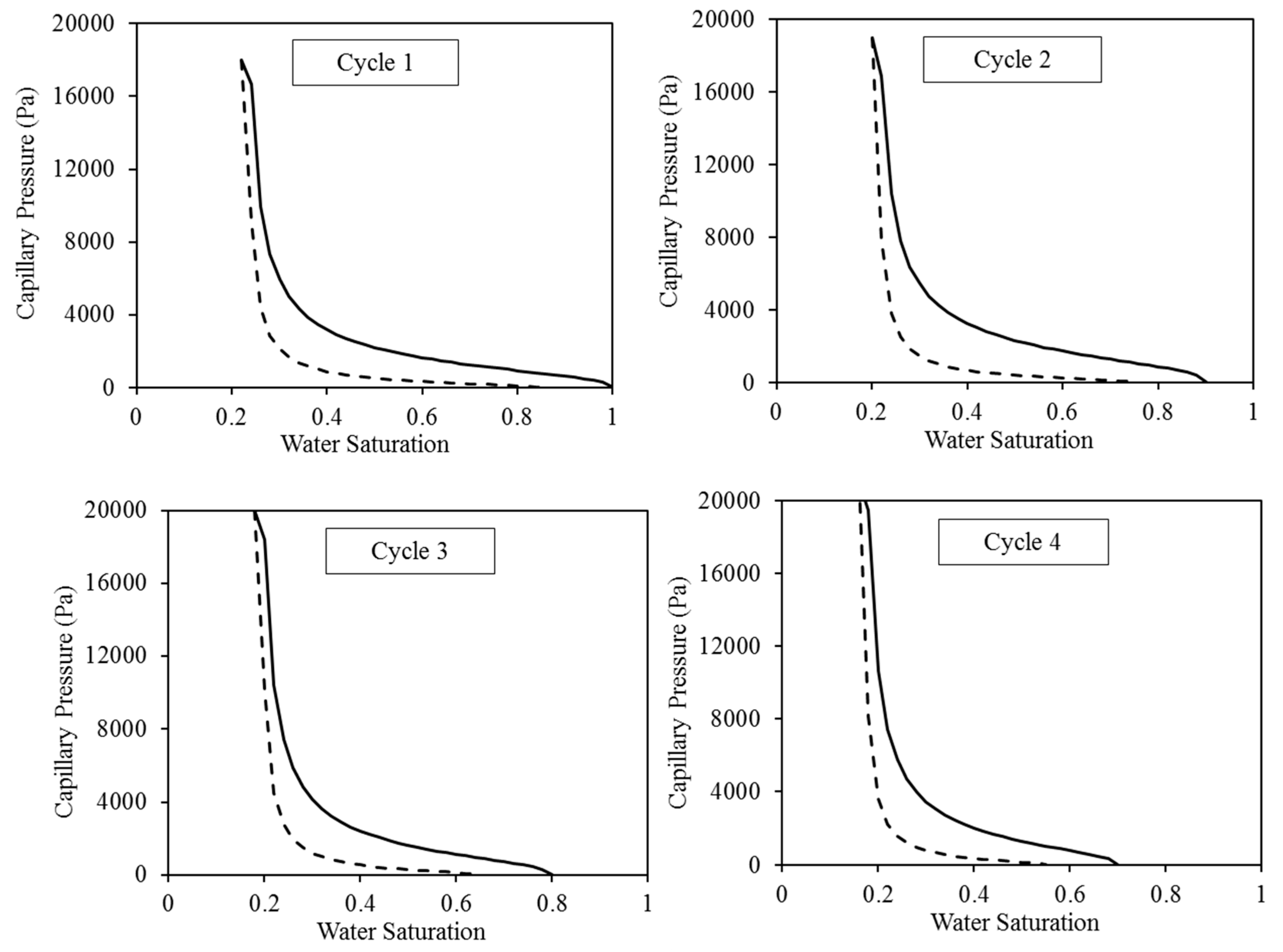
The major short-term trapping processes are structural and residual trapping, which is clearly apparent. These two processes’ performance is directly controlled by the corresponding relative permeability. Hence, it is imperative to meticulously choose these attributes. The evidence demonstrates that the characteristics curves, specifically the relative permeability and capillary pressure curves, exert a substantial influence on the fluid dynamics of the CO2-brine in the reservoir [45,46]. Therefore, in order to simulate the continuous injection of CO2 without injecting water, we utilised the pre-existing capillary pressure and relative permeability curves that were constructed specifically for an intermediate-wet environment [17,47]. The construction of these curves was based on empirical data [48,49,50]. The selection of intermediate-wet conditions was based on the high probability of encountering this wettability condition in aquifer systems containing CO2 and brine. McCaffery and Bennion’s [49] dataset was specifically utilised for constructing the relative permeability curves. We calibrated these curves using Craig’s criteria [48]. Therefore, in order to replicate the intermediate-wet wettability condition, we employed the specific values of 0.22 and 0.25 for the residual saturation of water and gas, respectively. Furthermore, the water saturation where the water and CO2 relative permeability are equal was chosen to be 0.5, in accordance with Craig’s empirical guideline. In all the injection cases, the initial values of the water and CO2 relative permeability are set to 1 and 0, respectively, representing the complete saturation of water at 100%. Throughout the initial CO2 injection process, the relative permeability of water steadily decreases, while the relative permeability of CO2 increases until it achieves its maximum value at the residual water saturation (Figure 3 and Figure 4). During the initial cycle of WAG, we employed a set of the residual saturation and initial saturation of the CO2 specific to the intermediate-wet rock. Subsequently, the residual saturation of CO2 has undergone improvements in cycles 2–4, which were reported in the experimental tests. The association between the initial and residual saturation of the CO2 matched the measurements conducted by Pentland et al. [51] during all four WAG cycles. Subsequently, the Genuchten–Mualem [52,53] approach was employed to include those curves via the TOUGH2 code:
where
= the relative permeability of gas, = the water relative permeability of water,
= the residual saturation of gas, = the water saturation,
= the saturated water saturation, = the residual saturation of water,
= the capillary pressure, = the scaling factor of the capillary pressure, and
= the pore size distribution index.
Furthermore, the Leverett J-function [54] was utilised to incorporate the influence of the reservoir heterogeneity on the capillary pressure curves for every individual grid cell:
where
= the capillary pressure (dimensionless), = the permeability,
= the porosity, = the contact angle, and = the interfacial tension.
Figure 3.
The relative permeability curves for water (shown by dotted lines) and CO2 (represented by solid lines) are utilised in the four WAG injection cycles. The top curve corresponds to CO2 injection, while the bottom curve corresponds to water injection.
Figure 3.
The relative permeability curves for water (shown by dotted lines) and CO2 (represented by solid lines) are utilised in the four WAG injection cycles. The top curve corresponds to CO2 injection, while the bottom curve corresponds to water injection.


Figure 4.
Capillary pressure curves employed for the four cycles of WAG injection. The solid lines reflect the CO2 injection, while the dashed lines illustrate the water injection.
Figure 4.
Capillary pressure curves employed for the four cycles of WAG injection. The solid lines reflect the CO2 injection, while the dashed lines illustrate the water injection.

3. Results and Discussion
To evaluate the reliability of storing CO2 in saline formations over a long period of time, it is necessary to anticipate how the CO2 will be distributed in space and how it will be divided between the gas, liquid, and solid phases. This prediction should cover both the injection phase and the subsequent hundreds to thousands of years. There are two types of CO2 migration in saline formations that are affected by changes in vertical permeability [11]. The first type happens in the shorter term when CO2 injection is performed at great depths within a thick and diverse formation. The objective is to enable the CO2 to ascend due to buoyancy while depending on the complex migration path to hinder its vertical movement. Here, it is necessary to assess the probability distribution of potential arrival times at a less deep level. This is especially crucial in cases when there is an absence of a regional seal or where there is a potential to impact hydrocarbon or groundwater resources in a different geological formation. Similar issues arise in the domain of pollutant transport in aquifer systems, where the presence of significant variations in hydraulic characteristics at a broad scale significantly impacts the downward movement of the plume [15,16]. The presence of dense formations presents a potential opportunity for storing significant amounts of CO2. However, it is crucial to ensure that the migration period from deep injection to the top of the formation is adequately slow. This is important because if the CO2 were to arrive too quickly, it might potentially disrupt the current resources. Under these circumstances, the variability in the potential arrival time becomes noteworthy rather than just the average value. The second type of occurrence takes place over a long period of time when the carbon dioxide (CO2) dissolves in the water present in the formation. This leads to a minor rise in density, which is typically enough to initiate gradual movement of the liquid phase, considerably expediting the entire process of dissolution [20].
In projects involving the storage of carbon dioxide, it is generally considered undesirable to have large levels of free mobile carbon dioxide saturation as well as vertical emissions of carbon dioxide. This is due to the fact that it increases the likelihood of carbon dioxide (CO2) moving from the reservoir to the surface, which is contrary to the objective of optimizing storage capacities. The purpose of this study is to evaluate the effect that the ratio of carbon dioxide to water has on the storage characteristics during water-alternating-gas injection. According to the findings, the utilisation of water alternating gas with different ratios of CO2 to water is able to effectively reduce the saturation of free mobile CO2 and restrict vertical CO2 migration. This is in contrast to situations in which there is no water injection utilised. In addition, our research indicates that an injection of carbon dioxide with a lower ratio of carbon dioxide to water results in lower levels of free mobile carbon dioxide saturation as well as vertical carbon dioxide migration. The results indicate that the average saturation of free mobile carbon dioxide was roughly thirty percent when there was no water input. When a CO2-water ratio of 2:1 was used, the saturation level dropped to approximately 20%, and when a CO2-water ratio of 1:1 was used, the saturation level dropped even further to approximately 15%. Eventually, it reached a minimum of around 10% when a CO2-water ratio of 1:2 was utilised, and this occurred after a storage time of one hundred years (Figure 5). Consequently, in general, injecting a low ratio of carbon dioxide to water results in a significant reduction in the mobility of carbon dioxide; this refers to the quantity of carbon dioxide that is able to move freely. When compared to the total amount of CO2 that was injected, the percentage of mobile CO2 that was injected was 6% when the ratio was 1:2, 16% when the ratio was 1:1, 22% when the ratio was 2:1, and 33% when there was no water injection (Figure 6).
Furthermore, the data presented in Figure 7, Figure 8 and Figure 9 clearly demonstrate that a low CO2-water ratio has a substantial positive impact on the efficiency of CO2 trapping. First and foremost, the findings indicate that a low ratio of CO2-water maximises the capillary trapping of CO2. After being stored for 100 years, 66% of the CO2 capillary was trapped when the CO2-water ratio was 1:2. In contrast, only 64%, 62%, and 57% of the CO2 was trapped in the other scenarios (1:1 CO2-water ratio, 2:1 CO2-water ratio, and no water injection, respectively; Figure 7).
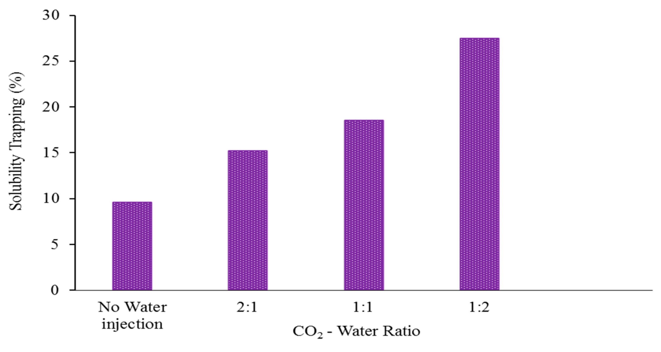
Moreover, a reduced CO2-water ratio also increased the effectiveness of the solubility trapping. It is crucial to note that only carbon dioxide (CO2) that is fully dissolved in water is securely retained and cannot escape back to the surface. For instance, after being stored for 100 years, 28% of the CO2 was effectively trapped through solubility when the ratio of CO2 to water was 1:2. By comparison, the percentages of CO2 stored in alternative situations were significantly lower: 18% for a 1:1 CO2-water ratio, 15% for a 2:1 CO2-water ratio, and 9% with no water injection (Figure 8). Additionally, the mean proportion of CO2 dissolved in the liquid phase (XCO2aq) at the close of the post-injection time (one hundred years) was approximately 0.05 for a CO2-water ratio of 1:2, whereas it was only around 0.04%, 0.035%, and 0.03% in the alternative scenarios (1:1 CO2-water ratio, 2:1 CO2-water ratio, and no water injection, respectively), Figure 9. Therefore, we draw the conclusion that a low CO2-water ratio significantly improves solubility, residual trapping, and the reduction in (unfavourable) CO2 mobility, all of which point to a significantly higher CO2 geo-sequestration efficiency. Thus, a low CO2-water ratio is the ideal injection strategy.
4. Conclusions
The storage of carbon dioxide in underground saline aquifers is now regarded as the most efficient solution for mitigating climate change by decreasing CO2 emissions [22]. Establishing an optimal CO2 injection technique or accurately assessing the different parameters (such as reservoir heterogeneity, caprock characteristics, rock wettability, and brine salinity) that affect CO2 trapping processes can both increase the effectiveness of CO2 storage in saline aquifers. While the WAG technique has been extensively employed to boost the efficiency of enhanced oil recovery (EOR) and CO2 storage activities, the impact of the CO2-water ratio during a WAG injection on the CO2 trapping effectiveness of heterogeneous reservoirs is still incompletely comprehended. In this study, we evaluated the impact of the CO2-water ratio on the efficiency of carbon dioxide storage in a heterogeneous reservoir. The findings of this study indicate that a low CO2-water ratio decreases the amount of free mobile CO2 saturation and vertical migration, maximises the amount of capillary trapping, and boosts the efficiency of solubility trapping in CO2 injection. Therefore, we can conclude that injecting WAG with a low ratio of CO2 to water can greatly improve the effectiveness of CO2 storage and the security of containment. The implications of our research are crucial for improving the efficiency of CO2 geo-sequestration, particularly in programmes that rely on residual and dissolution trapping for CO2 sequestration.
Funding
This research received no external funding.
Data Availability Statement
The data presented in this study are available on request from the corresponding author.
Conflicts of Interest
The authors declare no conflicts of interest.
References
- Riemer, P. Greenhouse gas mitigation technologies, an overview of the CO2 capture, storage and future activities of the IEA Greenhouse Gas R&D programme. Energy Convers. Manag. 1996, 37, 665–670. [Google Scholar]
- Kou, Z.; Wang, H.; Alvarado, V. Reservoir characterization and multiphase flow property in the upper Minnelusa sandstone: Implication for geological carbon storage. Adv. Geo-Energy Res. 2022, 6, 535–536. [Google Scholar] [CrossRef]
- Weir, G.J.; White, S.P.; Kissling, W.M. Reservoir storage and containment of greenhouse gases. Transp. Porous Media 1996, 23, 37–60. [Google Scholar] [CrossRef]
- Holloway, S. Underground sequestration of carbon dioxide—A viable greenhouse gas mitigation option. Energy 2005, 30, 2318–2333. [Google Scholar] [CrossRef]
- Zhang, L.; Li, X.; Ren, B.; Cui, G.; Zhang, Y.; Ren, S.; Chen, G.; Zhang, H. CO2 storage potential and trapping mechanisms in the H-59 block of Jilin oilfield China. Int. J. Greenh. Gas Control 2016, 49, 267–280. [Google Scholar] [CrossRef]
- Al-Khdheeawi, E.A.; Mahdi, D.S.; Yuan, Y.; Iglauer, S. Influence of Clay Content on CO2-Rock Interaction and Mineral-Trapping Capacity of Sandstone Reservoirs. Energies 2023, 16, 3489. [Google Scholar] [CrossRef]
- Xu, T.; Apps, J.A.; Pruess, K. Numerical simulation of CO2 disposal by mineral trapping in deep aquifers. Appl. Geochem. 2004, 19, 917–936. [Google Scholar] [CrossRef]
- Al-Khdheeawi, E.A.; Mahdi, D.S.; Hasan, M.M. Reservoir scale CO2-water-rock interactions and geochemical evolution of sandstone reservoirs due to CO2 geo-storage process. In AIP Conference Proceedings; AIP Publishing: Melville, NY, USA, 2022. [Google Scholar]
- Ning, Y.; Tura, A. Economic and operational investigation of CO2 sequestration through enhanced oil recovery in unconventional reservoirs in Colorado, USA. Geoenergy Sci. Eng. 2023, 226, 211820. [Google Scholar] [CrossRef]
- Song, H.; Huang, G.; Li, T.; Zhang, Y.; Lou, Y. Analytical model of CO2 storage efficiency in saline aquifer with vertical heterogeneity. J. Nat. Gas Sci. Eng. 2014, 18, 77–89. [Google Scholar] [CrossRef]
- Ashirbekov, A.; Kabdenova, B.; Kuljabekov, A.; Monaco, E.; Wang, L.; Rojas-Solórzano, L. Lattice Boltzmann pseudopotential multiphase modeling of transcritical CO2 flow using a crossover formulation. Adv. Geo-Energy Res. 2022, 6, 539–540. [Google Scholar] [CrossRef]
- Shariatipour, S.M.; Pickup, G.E.; Mackay, E.J. Simulations of CO2 storage in aquifer models with top surface morphology and transition zones. Int. J. Greenh. Gas Control 2016, 54, 117–128. [Google Scholar] [CrossRef]
- Prévost, J.H.; Fuller, R.; Altevogt, A.S.; Bruant, R.; Scherer, G. Numerical modeling of carbon dioxide injection and transport in deep saline aquifers. Greenh. Gas Control Technol. 2005, 7, 2189–2193. [Google Scholar]
- Metz, B.; Davidson, O.; De Coninck, H.C.; Loos, M.; Meyer, L. IPCC, 2005: IPCC Special Report on Carbon Dioxide Capture and Storage; Working Group III of the Intergovernmental Panel on Climate Change: Cambridge, UK; New York, NY, USA, 2005; 442p. [Google Scholar]
- Iglauer, S.; Al-Yaseri, A.Z.; Rezaee, R.; Lebedev, M. CO2 wettability of caprocks: Implications for structural storage capacity and containment security. Geophys. Res. Lett. 2015, 42, 9279–9284. [Google Scholar] [CrossRef]
- Al-Khdheeawi, E.A.; Mahdi, D.S.; Ali, M.; Fauziah, C.A.; Barifcani, A. Impact of caprock type on geochemical reactivity and mineral trapping efficiency of CO2. In Offshore Technology Conference Asia; OnePetro: Richardson, TX, USA, 2020. [Google Scholar]
- Al-Khdheeawi, E.A.; Vialle, S.; Barifcani, A.; Sarmadivaleh, M.; Iglauer, S. Impact of reservoir wettability and heterogeneity on CO2-plume migration and trapping capacity. Int. J. Greenh. Gas Control 2017, 58, 142–158. [Google Scholar] [CrossRef]
- Al-Khdheeawi, E.A.; Vialle, S.; Barifcani, A.; Sarmadivaleh, M.; Iglauer, S. Influence of CO2-wettability on CO2 migration and trapping capacity in deep saline aquifers. Greenh. Gases Sci. Technol. 2017, 7, 328–338. [Google Scholar] [CrossRef]
- Iglauer, S. Dissolution Trapping of Carbon Dioxide in Reservoir Formation Brine-a Carbon Storage Mechanism; INTECH Open Access Publisher: London, UK, 2011. [Google Scholar]
- Bachu, S.; Gunter, W.; Perkins, E. Aquifer disposal of CO2: Hydrodynamic and mineral trapping. Energy Convers. Manag. 1994, 35, 269–279. [Google Scholar] [CrossRef]
- Xu, T.; Apps, J.A.; Pruess, K. Reactive geochemical transport simulation to study mineral trapping for CO2 disposal in deep arenaceous formations. J. Geophys. Res. Solid Earth 2003, 108, 1–13. [Google Scholar] [CrossRef]
- Ambrose, W.A.; Lakshminarasimhan, S.; Holtz, M.H.; Núñez-López, V.; Hovorka, S.D.; Duncan, I. Geologic factors controlling CO2 storage capacity and permanence: Case studies based on experience with heterogeneity in oil and gas reservoirs applied to CO2 storage. Environ. Geol. 2008, 54, 1619–1633. [Google Scholar] [CrossRef]
- Arif, M.; Barifcani, A.; Lebedev, M.; Iglauer, S. Structural trapping capacity of oil-wet caprock as a function of pressure, temperature and salinity. Int. J. Greenh. Gas Control 2016, 50, 112–120. [Google Scholar] [CrossRef]
- Johnson, J.W.; Nitao, J.J.; Knauss, K.G. Reactive transport modeling of CO2 storage in saline aquifers to elucidate fundamental processes, trapping mechanisms and sequestration partitioning. Geol. Storage Carbon Dioxide 2004, 233, 107–128. [Google Scholar]
- Al-Khdheeawi, E.A.; Vialle, S.; Barifcani, A.; Sarmadivaleh, M.; Iglauer, S. Effect of brine salinity on CO2 plume migration and trapping capacity in deep saline aquifers. APPEA J. 2017, 57, 100–109. [Google Scholar] [CrossRef]
- Al-Khdheeawi, E.A.; Vialle, S.; Barifcani, A.; Sarmadivaleh, M.; Iglauer, S. Effect of wettability heterogeneity and reservoir temperature on CO 2 storage efficiency in deep saline aquifers. Int. J. Greenh. Gas Control 2018, 68, 216–229. [Google Scholar] [CrossRef]
- Blunt, M.J. Effects of heterogeneity and wetting on relative permeability using pore level modeling. SPE J. 1997, 2, 70–87. [Google Scholar] [CrossRef]
- Doughty, C.; Pruess, K. Modeling Supercritical CO2 Injection in Heterogneous Porous Media; Lawrence Berkeley National Laboratory: Berkeley, CA, USA, 2003. [Google Scholar]
- Flett, M.; Gurton, R.; Weir, G. Heterogeneous saline formations for carbon dioxide disposal: Impact of varying heterogeneity on containment and trapping. J. Pet. Sci. Eng. 2007, 57, 106–118. [Google Scholar] [CrossRef]
- Al-Khdheeawi, E.A.; Vialle, S.; Barifcani, A.; Sarmadivaleh, M.; Iglauer, S. Enhancement of CO2 trapping efficiency in heterogeneous reservoirs by water-alternating gas injection. Greenh. Gases Sci. Technol. 2018, 8, 920–931. [Google Scholar] [CrossRef]
- Joodaki, S.; Niemi, A.; Rasmusson, K.; Yang, Z.; Bensabat, J. Enhancement of CO2 Trapping in Saline Aquifers Using a Water-Alternating-Gas Method. 2016. Available online: https://ui.adsabs.harvard.edu/abs/2016EGUGA..18.8216J/abstract (accessed on 1 April 2016).
- Ahmadi, Y.; Eshraghi, S.E.; Bahrami, P.; Hasanbeygi, M.; Kazemzadeh, Y.; Vahedian, A. Comprehensive Water–Alternating-Gas (WAG) injection study to evaluate the most effective method based on heavy oil recovery and asphaltene precipitation tests. J. Pet. Sci. Eng. 2015, 133, 123–129. [Google Scholar] [CrossRef]
- Al-Bayati, D.; Al-Khdheeawi, E.; Saeedi, A.; Myers, M.; Xie, Q. Investigations of Miscible Water Alternating Gas Injection Efficiency in Layered Sandstone Porous Media. Iraqi J. Oil Gas Res. 2022, 2, 31–44. [Google Scholar] [CrossRef]
- Al-Ghanim, W.; Gharbi, R.; Algharaib, M.K. Designing a simultaneous water alternating gas process for optimizing oil recovery. In EUROPEC/EAGE Conference and Exhibition; Society of Petroleum Engineers: London, UK, 2009. [Google Scholar]
- Lei, H.; Yang, S.; Zu, L.; Wang, Z.; Li, Y. Oil Recovery Performance and CO2 Storage Potential of CO2 Water-Alternating-Gas Injection after Continuous CO2 Injection in a Multilayer Formation. Energy Fuels 2016, 30, 8922–8931. [Google Scholar] [CrossRef]
- Chen, S.; Li, H.; Yang, D.; Tontiwachwuthikul, P. Optimal parametric design for water-alternating-gas (WAG) process in a CO2-miscible flooding reservoir. J. Can. Pet. Technol. 2010, 49, 75–82. [Google Scholar] [CrossRef]
- Shahverdi, H.; Sohrabi, M. An improved three-phase relative permeability and hysteresis model for the simulation of a water-alternating-gas injection. SPE J. 2013, 18, 841–850. [Google Scholar] [CrossRef]
- Le Van, S.; Chon, B. Applicability of an Artificial Neural Network for Predicting Water-Alternating-CO2 Performance. Energies 2017, 10, 842. [Google Scholar] [CrossRef]
- Laochamroonvorapongse, R.; Kabir, C.; Lake, L.W. Performance assessment of miscible and immiscible water-alternating gas floods with simple tools. J. Pet. Sci. Eng. 2014, 122, 18–30. [Google Scholar] [CrossRef]
- Nghiem, L.; Shrivastava, V.; Kohse, B.; Hassam, M.; Yang, C. Simulation and optimization of trapping processes for CO2 storage in saline aquifers. J. Can. Pet. Technol. 2010, 49, 15–22. [Google Scholar] [CrossRef]
- Dake, L.P. Fundamentals of Reservoir Engineering; Elsevier: Amsterdam, The Netherlands, 2007; Volume 8. [Google Scholar]
- Pruess, K. ECO2M: A TOUGH2 Fluid Property Module for Mixtures of Water, NaCl, and CO2, Including Super-and Sub-Critical Conditions, and Phase Change between Liquid and Gaseous CO2; Lawrence Berkeley National Laboratory: Berkeley, CA, USA, 2011. [Google Scholar]
- Pruess, K.; Oldenburg, C.; Moridis, G. TOUGH2 User’s Guide Version 2; Lawrence Berkeley National Laboratory: Berkeley, CA, USA, 1999. [Google Scholar]
- Pruess, K. ECO2N: A TOUGH2 Fluid Property Module for Mixtures of Water, NaCl, and CO2; Lawrence Berkeley National Laboratory: Berkeley, CA, USA, 2005. [Google Scholar]
- Doster, F.; Nordbotten, J.; Celia, M. Impact of capillary hysteresis and trapping on vertically integrated models for CO2 storage. Adv. Water Resour. 2013, 62, 465–474. [Google Scholar] [CrossRef]
- Doughty, C. Modeling geologic storage of carbon dioxide: Comparison of non-hysteretic and hysteretic characteristic curves. Energy Convers. Manag. 2007, 48, 1768–1781. [Google Scholar] [CrossRef]
- Al-Khdheeawi, E.A.; Vialle, S.; Barifcani, A.; Sarmadivaleh, M.; Iglauer, S. Influence of injection well configuration and rock wettability on CO2 plume behaviour and CO2 trapping capacity in heterogeneous reservoirs. J. Nat. Gas Sci. Eng. 2017, 43, 190–206. [Google Scholar] [CrossRef]
- Craig, F.F. The Reservoir Engineering Aspects of Waterflooding; Henry L. Doherty Memorial Fund of AIME, Society of Petroleum Engineers: Richardson, TX, USA, 1993; Volume 3. [Google Scholar]
- McCaffery, F.; Bennion, D. The Effect of Wettability on Two-Phase Relative Pemeabilities. J. Can. Pet. Technol. 1974, 13. [Google Scholar] [CrossRef]
- Batycky, J.P.; McCaffery, F.G.; Hodgins, P.K.; Fisher, D.B. Interpreting relative permeability and wettability from unsteady-state displacement measurements. Soc. Pet. Eng. J. 1981, 21, 296–308. [Google Scholar] [CrossRef]
- Pentland, C.H.; El-Maghraby, R.; Iglauer, S.; Blunt, M.J. Measurements of the capillary trapping of super-critical carbon dioxide in Berea sandstone. Geophys. Res. Lett. 2011, 38. [Google Scholar] [CrossRef]
- Van Genuchten, M.T. A closed-form equation for predicting the hydraulic conductivity of unsaturated soils. Soil Sci. Soc. Am. J. 1980, 44, 892–898. [Google Scholar] [CrossRef]
- Mualem, Y. A new model for predicting the hydraulic conductivity of unsaturated porous media. Water Resour. Res. 1976, 12, 513–522. [Google Scholar] [CrossRef]
- Leverett, M. Capillary behavior in porous solids. Trans. AIME 1941, 142, 152–169. [Google Scholar] [CrossRef]
Figure 1.
The developed reservoir model showing reservoir heterogeneity.

Figure 2.
The pressure changes with the injection of CO2.

Figure 5.
Two-dimensional cross-sectional viewpoints of the reservoir displaying the CO2 plume with the saturation of supercritical CO2 for the different CO2-water ratio scenarios at the end of the CO2 storage period.
Figure 5.
Two-dimensional cross-sectional viewpoints of the reservoir displaying the CO2 plume with the saturation of supercritical CO2 for the different CO2-water ratio scenarios at the end of the CO2 storage period.

Figure 6.
The proportion of free CO2 relative to the total amount of injected CO2, expressed as a function of the CO2-water ratio at the completion of the CO2 storage period. The CO2-water ratio strategy of 1:2 is considered to be the most optimal.
Figure 6.
The proportion of free CO2 relative to the total amount of injected CO2, expressed as a function of the CO2-water ratio at the completion of the CO2 storage period. The CO2-water ratio strategy of 1:2 is considered to be the most optimal.

Figure 7.
The ratio of CO2 that is trapped in capillary compared to the total amount of CO2 injected, represented as a function of the ratio of CO2 to water at the end of the CO2 storage period. The 1:2 CO2-water ratio is regarded as the most optimal.
Figure 7.
The ratio of CO2 that is trapped in capillary compared to the total amount of CO2 injected, represented as a function of the ratio of CO2 to water at the end of the CO2 storage period. The 1:2 CO2-water ratio is regarded as the most optimal.

Figure 8.
The ratio of CO2 that is trapped in solubility trapping compared to the total amount of CO2 injected, represented as a function of the ratio of CO2 to water at the end of the CO2 storage period. The 1:2 CO2-water ratio is regarded as the most optimal.
Figure 8.
The ratio of CO2 that is trapped in solubility trapping compared to the total amount of CO2 injected, represented as a function of the ratio of CO2 to water at the end of the CO2 storage period. The 1:2 CO2-water ratio is regarded as the most optimal.

Figure 9.
Dissolved CO2 mass fraction as a function of the CO2-water ratio, at the end of the CO2 storage time.
Figure 9.
Dissolved CO2 mass fraction as a function of the CO2-water ratio, at the end of the CO2 storage time.


Table 1.
CO2 and water injection rates for the investigated CO2-water ratio scenarios.
| CO2—Water Ratio | CO2 Injection Rate (Million Ton/Year) | Total CO2 Injected (Million Ton) | Water Injection Rate (Million Ton/Year) | Total Injected Water (Million Ton) |
|---|---|---|---|---|
| No water injection | 1.0 | 4.0 | not applicable | not applicable |
| 2:1 | 1.0 | 4.0 | 0.5 | 2.0 |
| 1:1 | 1.0 | 4.0 | 1.0 | 4.0 |
| 1:2 | 1.0 | 4.0 | 2.0 | 8.0 |
Disclaimer/Publisher’s Note: The statements, opinions and data contained in all publications are solely those of the individual author(s) and contributor(s) and not of MDPI and/or the editor(s). MDPI and/or the editor(s) disclaim responsibility for any injury to people or property resulting from any ideas, methods, instructions or products referred to in the content. |
© 2024 by the author. Licensee MDPI, Basel, Switzerland. This article is an open access article distributed under the terms and conditions of the Creative Commons Attribution (CC BY) license (https://creativecommons.org/licenses/by/4.0/).
Share and Cite
MDPI and ACS Style
Al-Khdheeawi, E.A. Optimizing CO2-Water Injection Ratio in Heterogeneous Reservoirs: Implications for CO2 Geo-Storage. Energies 2024, 17, 678. https://doi.org/10.3390/en17030678
AMA Style
Al-Khdheeawi EA. Optimizing CO2-Water Injection Ratio in Heterogeneous Reservoirs: Implications for CO2 Geo-Storage. Energies. 2024; 17(3):678. https://doi.org/10.3390/en17030678
Chicago/Turabian StyleAl-Khdheeawi, Emad A. 2024. "Optimizing CO2-Water Injection Ratio in Heterogeneous Reservoirs: Implications for CO2 Geo-Storage" Energies 17, no. 3: 678. https://doi.org/10.3390/en17030678
Note that from the first issue of 2016, this journal uses article numbers instead of page numbers. See further details here.