Article

Influence of Environmental Conditions on the Electrical Parameters of Side Connectors in Glass–Glass Photovoltaic Modules

by
Krzysztof Barbusiński
1,
Paweł Kwaśnicki
2,3,*,
Anna Gronba-Chyła
2,
Agnieszka Generowicz
4,*,
Józef Ciuła
5,
Bartosz Szeląg
6,
Francesco Fatone
7,
Agnieszka Makara
8 and
Zygmunt Kowalski
9
1
Department of Water and Wastewater Engineering, Silesian University of Technology, 44-100 Gliwice, Poland
2
Faculty of Natural and Technical Sciences, John Paul II Catholic University of Lublin, 20-708 Lublin, Poland
3
Research & Development Centre for Photovoltaics, ML System S.A., 36-062 Zaczernie, Poland
4
Department of Environmental Technologies, Cracow University of Technology, 31-155 Kraków, Poland
5
Faculty of Engineering Sciences, State University of Applied Sciences in Nowy Sącz, 33-300 Nowy Sącz, Poland
6
Department of Hydraulics and Sanitary Engineering, Institute of Environmental Engineering, Warsaw University of Life Sciences, 02-787 Warsaw, Poland
7
Department of Science and Engineering of Matter, Environment and Urban Planning (SIMAU), Polytechnic University of Marche Ancona, 60121 Ancona, Italy
8
Faculty of Chemical Engineering and Technology, Cracow University of Technology, 31-155 Kraków, Poland
9
Mineral and Energy Economy Research Institute, Polish Academy of Sciences, 31-261 Krakoów, Poland
*
Authors to whom correspondence should be addressed.
Energies 2024, 17(3), 680; https://doi.org/10.3390/en17030680
Submission received: 21 December 2023 / Revised: 17 January 2024 / Accepted: 27 January 2024 / Published: 31 January 2024
(This article belongs to the Collection Renewable and Sustainable Energy)

Abstract

:
This work focused on the verification of the electrical parameters and the durability of side connectors installed in glass–glass photovoltaic modules. Ensuring the safe use of photovoltaic modules is achieved, among others, by using electrical connectors connecting the PV cell circuit inside the laminate with an external electric cable. In most of the cases for standard PV modules, the electrical connector in the form of a junction box is attached from the back side of the PV module. The junction box is glued to the module surface with silicone where the busbars were previously brought out of the laminate through specially prepared holes. An alternative method is to place connectors on the edge of the module, laminating part of it. In such a case, the specially prepared “wings” of the connector are tightly and permanently connected using laminating foil, between two glass panes protecting against an electrical breakdown. Additionally, this approach eliminates the process of preparing holes on the back side of the module, which is especially complicated and time-consuming in the case of glass–glass modules. Moreover, side connectors are desirable in BIPV applications because they allow for a more flexible design of installations on façades and walls of buildings. A series of samples were prepared in the form of PV G-G modules with side connectors, which were then subjected to testing the connectors for the influence of environmental conditions. All samples were characterized before and after the effect of environmental conditions according to PN-EN-61215-2 standards. Insulation resistance tests were performed in dry and wet conditions, ensuring full contact of the tested sample with water. For all modules, before being placed in the climatic chamber, the resistance values were far above the minimum value required by the standards, allowing the module to be safely used. For the dry tests, the resistance values were in the range of GΩ, while for the wet tests, the obtained values were in the range of MΩ. In further work, the modules were subjected to environmental influences in accordance with MQT-11, MQT-12, and MQT-13 and then subjected to electrical measurements again. A simulation of the impact of changing climatic conditions on the module test showed that the insulation resistance value is reduced by an order of magnitude for both the dry and wet tests. Additionally, one can observe visual changes where the lamination foil is in contact with the connector. The measurements carried out in this work show the potential of side connectors and their advantage over rear junction boxes, but also the technological challenges that need to be overcome.

1. Introduction

Photovoltaic modules, commonly known as solar panels, have emerged as a revolutionary technology in the realm of renewable energy. As the global pursuit of sustainable and clean energy solutions intensifies, photovoltaic modules play a pivotal role in harvesting the power of the sun to generate electricity [1,2]. The popularity of glass/glass (G/G) photovoltaic (PV) module designs is growing rapidly due to an increased demand for bifacial photovoltaic (PV) modules, with additional applications in thin-film and building-integrated technologies. G/G modules are expected to withstand harsh environmental conditions and extend the life of installed modules to over 30 years compared to conventional glass/backsheet (G/B) modules [3,4].
One of the main elements of interest in the introduction of photovoltaic energy is the construction of integrated photovoltaic (BIPV) systems [5,6]. Given the rapid development of photovoltaic power plants, understanding the performance and reliability of such systems is becoming even more important [7]. Recently, one of the main factors driving the growth of the BIPV market are increasingly demanding regulations related to the energy efficiency of buildings. The building sector, responsible for 40% of total energy consumption in the EU, provides largely untapped and cost-effective energy-saving potential [8]. Energy-related directives and building codes and standards are therefore some of the most important measures for energy efficiency in buildings. In the EU, for example, the Energy Performance of Buildings Directive [9] 2010/31/EU and the Energy Efficiency Directive [10] 2012/27/EU are the main regulations for reducing energy consumption in buildings. By simultaneously serving as a building façade and an energy generator, building-integrated photovoltaic systems can provide savings in materials and electricity costs [11]. Currently, photovoltaic modules for integration with buildings are produced as a standard construction product, and by matching standard façade and roof structures, these elements have created a completely new market: BIPVs [12]. The problem of BIPV systems is power loss caused by temperature increases, because the modules often operate close to the building’s external walls with poor ventilation [13]. As BIPVs continue to evolve, it is even more necessary to improve the tools available for optimal electrical design and simulation of BIPV systems. This means correctly modeling the performance of such BIPV systems, which includes modeling the PV module temperature [14,15]. Appropriate standardization for assessing heat transfer and solar heat gains of BIPV modules still requires further development because BIPV elements behave differently from the building elements they replace. The optical properties of BIPV modules, such as light transmittance or color reproduction, also play a role in finding a good balance among energy savings, electricity generation, esthetics, and visual comfort [16]. Lopez-Garcia et al. claim that double-sided c-Si photovoltaic (PV) modules can increase the efficiency of traditional photovoltaic modules because both sides of the cells, front and back, absorb solar radiation [17].
The reliability of the junction box is one of the most important issues in the proper operation of PV. On average, 85% of junction box failures have their source in the system installation and most often occur within the first three months of the photovoltaic system’s installation [18,19]. The main causes include excessive stress in the system, poor attachment of the junction box to the rear wall, poorly closed cover, moisture, and incorrect wiring [20]. In the work, Madeti et al. divided photovoltaic failures into reversible, lasting for a certain period of time, that is, dust accumulation and shading by snow cover. The second division is permanent failures, that is, for example, discoloration of the housing [21]. It focused on techniques for detecting photovoltaic failures and separate failures based on their occurrence due to environmental and electrical stress factors such as short circuits (e.g., line to ground and line to line), power conversion unit failures (e.g., inverter failures), and arc faults [22]. The literature still lacks an in-depth, state-of-the-art review that provides detailed information on the failures encountered in the PV module itself [23,24]. Electrical failures related to the concentration of heat and thermomechanical stresses inside junction boxes are one of the main types of photovoltaic (PV) module failures. Three types of partial solar panel junction boxes with 72 Si cells are modeled under constant-state constant-current conditions. Junction boxes typically contain bypass diodes to protect the cells in the event of shading or cell problems. Separating the diode from the junction box can prevent temperature increases and failures [25]. It was found that the most common causes of early failures are junction box failure, glass breakage, faulty cell connection, loose frame, and delamination [26]. The design of a sustainable photovoltaic (PV) module with high output power under failure and hot-spot conditions is presented. The proposed photovoltaic module has two junction boxes: one at the top and the other at the bottom. The upper field contains the upper terminals of each substring, while the lower field contains the lower terminals of each substring [27]. An important aspect is the appropriate recycling of junction boxes [28,29].
In a photovoltaic module, many individual solar cells are electrically connected to increase their power output. The cells and connections are then packaged to (1) protect the electrical circuit from the elements, (2) provide structural stability and protect the mechanical integrity of the cells, and (3) isolate the electrical circuit from the environment, protecting operators from electrical shock [30]. The design of the bifacial module, in particular the junction box, nameplate, and frame location on the rear side, plays an important role in the rear performance of the module [17]. The cells are transparently encapsulated toward the glass pane and also toward the rear side. A back cover seals the module at the rear side, where the junction box and connection cables are mounted [31,32]. One can find in the literature a large number of the described types of two-surface modules, but a lot of them have a bad design, because they locate junction boxes shading the solar cells and overlapping frames at the back of the module, causing shading [33].
The junction box structure consists of a body and cover that are almost exclusively made of an injection-molded polymer structure and are glued to the module substrate using an adhesive that is compatible with both the junction box polymer and the PV module substrate [34,35]. The combination of the housing, bypass diode, jumper wiring, connectors, and adhesive make the junction box a complex component that appears simple and is not intended to be maintained or serviced. This combination of system behavior and lack of maintainability poses a challenge for the manufacturer of photovoltaic modules, where a 25-year service life is expected [36,37,38,39]. Delamination can be a cause of immediate concern for both performance and safety if it occurs at the edge of a module or near a junction box, as it can cause the current to leak or disconnect the box. If delamination occurs in the center of the module, it can increase the thermal resistance and lead to a higher operating temperature of the cells in this area and act as a water condensation point [40,41,42]. Bypass diodes are usually integrated in the junction box and are quite a common source of problems in poorly performing or damaged modules [43,44,45]. The junction box is usually located at the rear of the PV module, less often on its edge. It protects string connections, external wiring, and often bypass diodes. The box is usually made of polycarbonate and glued to the back of the module [46]. In documented module failures, the junction box is a fairly common problem [47]. The main failure modes of junction boxes include disconnection (from the back of the module), poorly sealed or closed boxes, corrosion, and arcing due to poor or damaged wiring [48].
One key component that enhances the efficiency and functionality of these solar panels is the side junction box. Traditionally, solar panels have been equipped with junction boxes located on the rear side. However, the evolution of solar technology has given rise to a new design paradigm especially important in building integrated photovoltaics, featuring side-mounted junction boxes. This innovation not only addresses specific challenges associated with rear junction boxes but also brings about notable advantages in terms of installation, maintenance, and overall performance.
A side junction box for photovoltaic (PV) modules is a crucial element in solar panel design, offering unique advantages and addressing specific challenges associated with traditional rear-mounted junction boxes. This innovative approach involves relocating the junction box from the rear surface of the solar panel to one of its sides, introducing a range of benefits that contribute to the overall efficiency and reliability of the PV system.
One of the primary advantages of side junction boxes is enhanced ease of installation. This aspect is particularly important for BIPV installation. Traditional rear junction boxes can pose challenges during the mounting process, requiring careful consideration to avoid shading effects and ensuring proper alignment. By moving the junction box to the side, solar panels with side junction boxes simplify installation procedures, reduce shading concerns, and provide greater flexibility in system design. Furthermore, maintenance also becomes more accessible with side-mounted junction boxes. The side placement allows for easier access to the electrical components, streamlining inspection and repair tasks. If the JB is placed in the rear part of the module, for BIPV applications (ventilated façade, second skin), it is necessary to remove the entire module or even several modules to perform an inspection, while placing the JB on the edge of the module allows for inspection of the connection elements without the need to dismantle This can significantly reduce downtime and maintenance costs associated with solar panel systems.
Additionally, side junction boxes contribute to improved heat dissipation. Solar panels generate heat during operation, and efficient dissipation is crucial for maintaining optimal performance and longevity. Side-mounted junction boxes facilitate better heat dissipation, preventing excessive temperature build-up and ensuring the longevity of both the electrical components and the solar panels themselves. The lack of protrusions from the rear surface of the PV module (which occurs in standard JB) does not interfere with the airflow in BIPV installations, especially in ventilated facades, which has a positive effect on the thermal performance of the building. Furthermore, the design of side junction boxes often incorporates enhanced weather resistance [49,50]. Placing the junction box on the side minimizes exposure to direct sunlight and environmental elements, offering improved protection against moisture, dust, and other potential sources of damage. This robust design contributes to the long-term durability of the PV modules [51].
While side junction boxes for photovoltaic (PV) modules offer several advantages, it is important to acknowledge potential disadvantages and challenges associated with this design. One of the most important is related to the limitation in terms of size: the placement of a side junction box imposes constraints on the size and dimensions of the PV module, which in turn can affect the overall power output of the solar pane. Side-mounted junction boxes are also more exposed compared to rear-mounted ones, making them potentially more susceptible to physical damage from external factors such as impacts or accidental contact. Nonetheless, for BIPV applications, side JBs can be easily integrated into the structural elements, such as frames or mounting systems, which will provide additional protection against mechanical damage.
For solar panels integrated into architectural designs, BIPVs must meet esthetic requirements, and the appearance of the installation is a significant factor for residential and commercial applications. Some individuals may find the appearance of side junction boxes less visually appealing than rear-mounted alternatives, potentially influencing the choice of solar panel systems. Nevertheless, the most important factor seems to be electrical safety.
In this work, we focus on the significance of photovoltaic modules with side junction boxes, highlighting their electrical performance and safety. The presented work shows the technological challenges that must be overcome in order to safely use side connectors in BIPV installations.

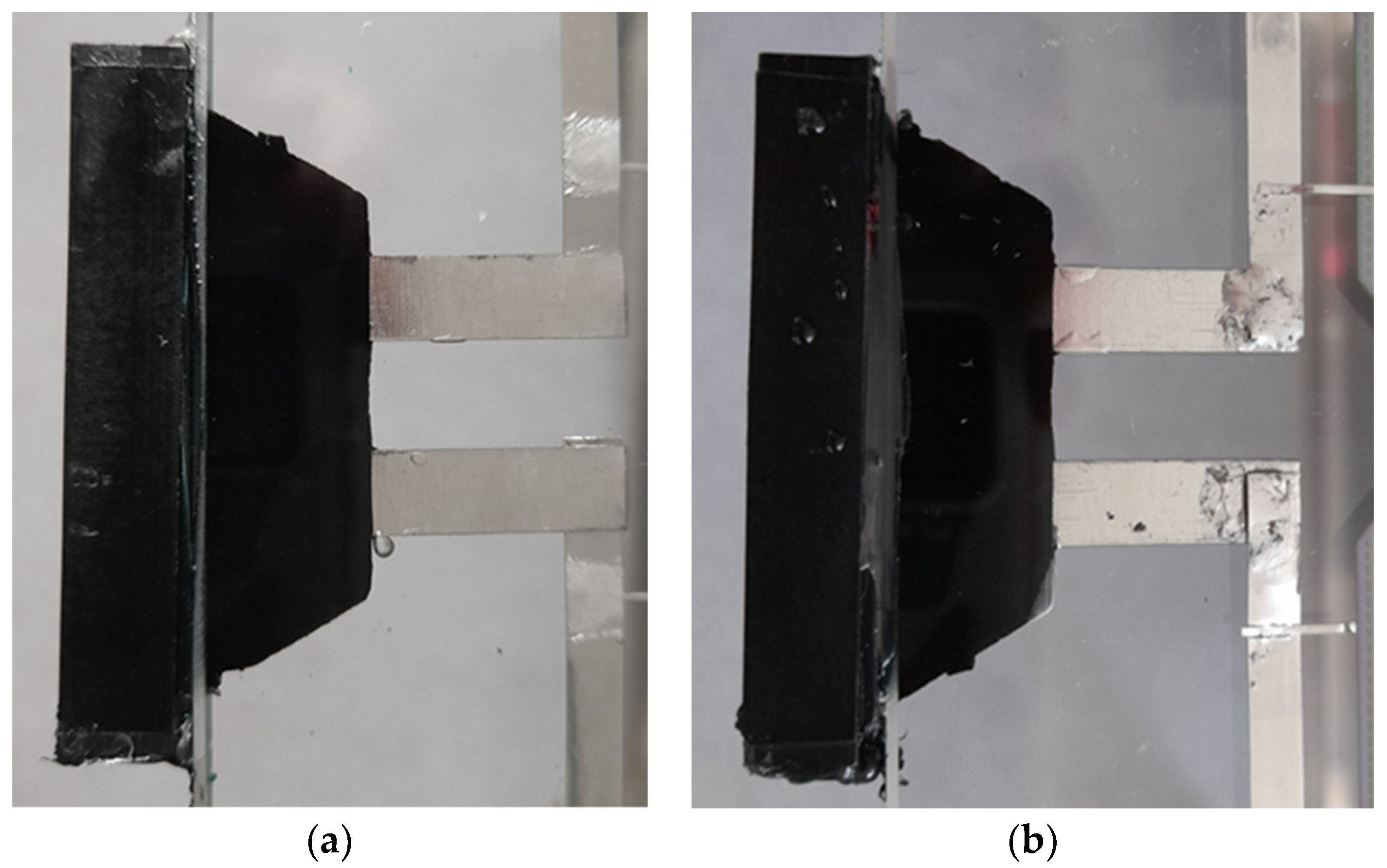
2. Materials and Methods

For the tests, a series of samples were prepared. Measured modules were made using standard front-contact solar cells and 4 mm low-iron glass sheets as a front component. Used solar cells were combined into strings and laminated using 0.76 mm thick PVB lamination foil. As side connectors, an element with external dimension of 40.4 mm × 9.0 mm and internal dimension (between glass sheets) of 32 mm × 1.5 mm made of PPE with copper electrical components was used. Two types of modules were prepared that differ in dimension: 1030 × 1050 mm and 10305 × 885 mm. Every one of the PV modules was equipped with side junction box. The samples subjected to climatic tests are listed in Table 1.
All of the samples were subjected to following tests:
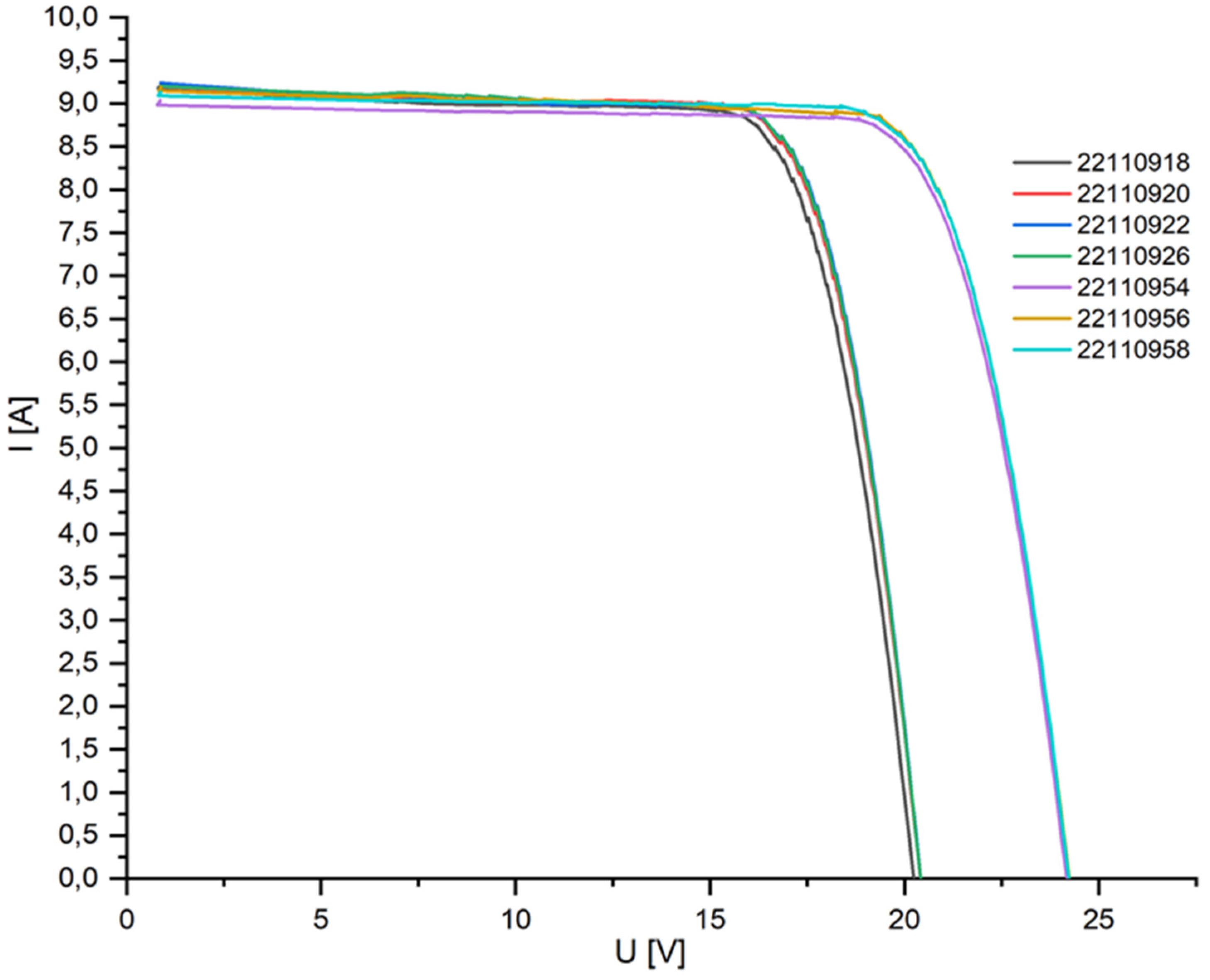
  • determining the current–voltage characteristics using the Flasher Berger PSL8 (BERGER Lichttechnik GmbH & Co. KG i.L. Pullach, Germany) solar simulator;
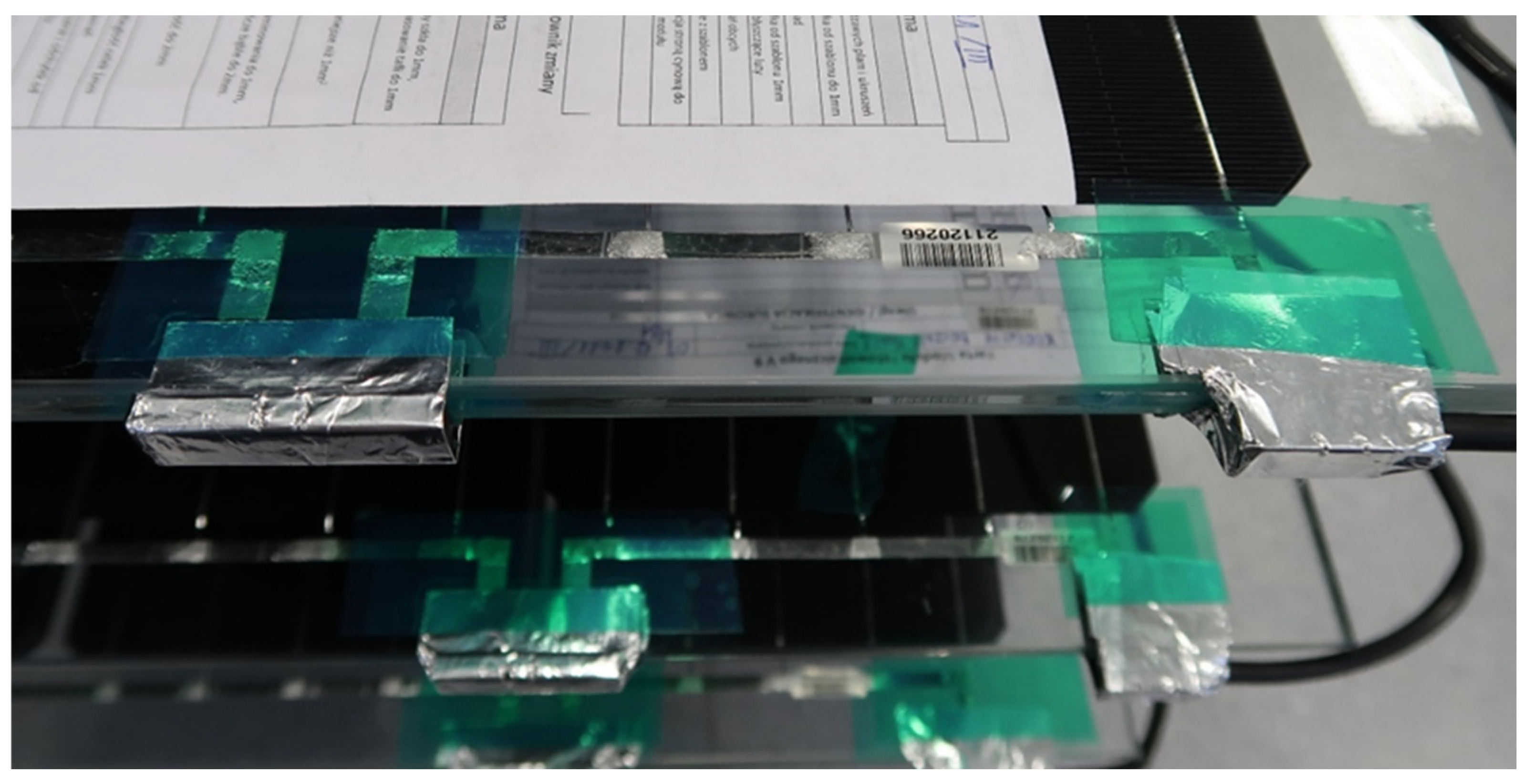
  • insulation resistance test using the Sonel MIC-2500 m (Sonel, Świdnica, Poland);
  • testing of the resistance of PV modules to changing climatic conditions was carried out using a large ACS KeyKratos Plus climatic chamber (ACS, Massa Martana, Italy).

3. Results

The samples were tested for resistance to changing climatic conditions in accordance with the PN-EN IEC 61215-2 [52] standards. Before placing the modules in the chamber, a visual inspection was performed and the U-I characteristic was determined. During the test, the temperature inside the chamber was set up to 85 °C and humidity to 85+/−5% RH, in accordance with the IEC 61215-2 norm.
A slight difference in voltage values was noticed. Three modules, 22110920, 22110926, and 2211091, have Voc value in the range of 20 V, while for the other modules, this value is around 24 V. Because the same type of solar cells was used for all the modules, 5BBs, M 156.75 of 23.5% eff and power of 5.74 W, the reason for the differences between modules is mostly related to their size. For some module assemblies, inaccuracies were noticed in the electrical paths (Figure 1); nonetheless this has no effect on insulation resistance measurements.
The repeatability of the modules made can be seen from the I–V curve graph. There are no signs indicating module damage or incorrect operation of the bypass diode. Additionally, no discrepancies between the measured current and voltage values for the modules and the total values resulting from the cells used were observed, which indicates correct operation of the system.
In the next step, the insulation resistance was tested in “dry” and “wet” conditions in accordance with the PN-EN-61215-2 [52] standard, where a voltage of 1000 V was applied to the module. Additionally, before the aging tests, the insulation resistance was determined at a voltage of 2500 V. The results of the survey are shown in Figure 2. To ensure good electrical contact with the tested connector surface, the edges of the module were covered with aluminum foil as shown in Figure 3.
The module was short-circuited with a branching connector, and then the positive electrode was connected to the measuring device. A second electrode was connected to the edge wrapped in foil.
The research was carried out according to the plan below:
(a)
I insulation resistance test;
(b)
MQT-11 test, several cycles of 6 h each, T: <−40,+85> °C, uncontrolled humidity;
(c)
MQT-12 test, several cycles of 24 h each, T: <−40,+85> °C, humidity 85% at T = 85 °C for 20 h;
(d)
MQT-13 test, half cycle—20 days;
(e)
II insulation resistance test.
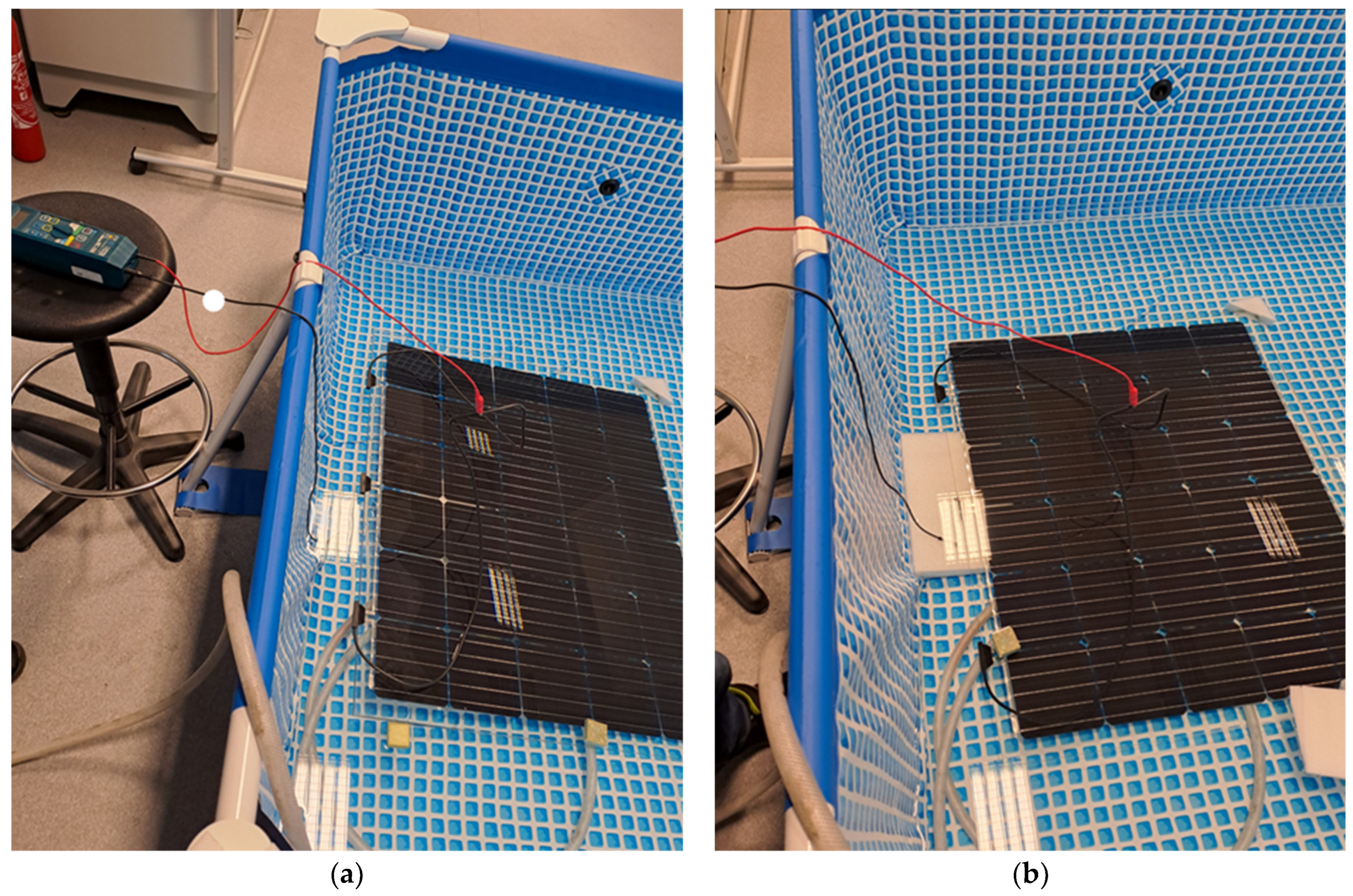
Wet insulation resistance results were recorded for each PV module (before and after aging testing) at
(a)
a module immersed in water, with the connectors located above the water surface (to eliminate the likelihood of a breakdown occurring on the module itself)—Figure 4a;
(b)
module immersed in water with connectors—Figure 4b.
The insulation resistance results before the climatic test are presented in Table 2. The measurements were performed for different voltages applied ranging from 1 kV to 2.5 kV for the dry and wet tests and for modules fully and half-immersed (M/2) in water. For the half-immersed module, the connector was placed above the water surface. The insulation resistance was determined for 1 and 2.5 kV.
According to the PN-EN-61215-2 [52] standard, the insulation resistance value of the measured modules cannot be less than 40 MΩ · m2 for modules larger than 0.1 m2. The area of the tested modules is 1.035 m · 1.050 m = 1.087 m2 and 1.035 m · 0.885 m = 0.916 m2. Therefore, the limit values of the insulation resistance for the tested modules should be 40 MΩ · 1.087 m2 = 43.48 MΩ and 40 MΩ · 0.916 m2 = 36.64 MΩ. For the dry tests, the measured resistance values are in the range of GΩ, significantly exceeding the normative requirements for electrical safety for both the 1 and 2.5 kV voltages applied. Lower values by a factor of 10 values were obtained for the wet tests when only half of the module was immersed in water and the connector was not submerged. The fully submerged modules, the 1 kV 5 module, showed values meeting the requirements of the standard, and for module 22110922, an electrical breakdown was noticed. Only one module met the standards when the 2.5 kV voltage was applied.
Figure 4. PV modules during “wet” insulation resistance measurement—on the left (a), the module is immersed, excluding connectors—connectors above the water surface; on the right side (b), the module is immersed in water together with the connectors.
Energies 17 00680 g004
After the aging tests, the module was subjected to visual inspection. No changes in the module itself were noticed. Slight color changes were noticed on the connectors, and the external part of the junction boxes turned whitish (Figure 5). No significant changes in regard to the mechanical properties of the junction box material were noticed.
Table 3 summarizes the obtained values of insulation resistance of the tested modules after the aging chamber. For all measured modules for the 2.5 kV applied voltage, the electrical breakdown was noticed even for the “dry” measurements, so due to safety reasons, wet test measurements were not carried out. Furthermore, for safety reasons, no detailed performance characteristic of the module was performed.

4. Discussion

Electrical breakdown in a photovoltaic junction box (JB) can occur due to various reasons; for side JBs, because this technology is still being developed, detail characterization for a comprehensive understanding is needed. To prevent an electrical breakdown in a PV junction box, it is crucial to ensure proper design, installation, and maintenance. This includes using high-quality materials, proper sealing, and effective insulation and adherence to industry standards and guidelines. The characterized samples clearly show that in order to ensure electrical safety, the manufacture process, design of JB, and insulation must be improved. The most common reasons why an electrical breakdown may occur in a PV junction box are moisture ingress; corrosion on electrical contacts, wires, and other components within the junction box; overheating; poor workmanship; defective components such as diodes or connectors; voltage spikes, surges, or overvoltage conditions; and material degradation due to exposure to sunlight, temperature variations, and other environmental factors. No changes in the material itself, namely nylon PA66, after the climate tests were noticed, suggesting that this fabric can be used for JBs. Because there is no breakdown for all the dry tests, one can conclude that the electrical connections of ribbons for solar cells and the connections to the junction boxes were prepared correctly. No problems related to electrical safety were noted when the module was immersed in water in such a way that the junction box remained above the water surface. The obtained values did not differ from those obtained in the case of the dry tests. This clearly suggests that the module was designed and assembled properly and the lamination process was performed correctly. For the wet tests, for 2.5 kV, five of the seven modules demonstrated an electrical breakdown. Additionally, for the applied voltage of 1 kV for the wet tests, for almost all modules, a significant drop by a factor of over 2 was noticed regarding the measured resistance compared to the dry tests. The possible explanation for the significant reduction in the insulation resistance values can be related to the lamination process. For the glass–glass module, a PVB lamination foil with a thickness of 0.76 mm was used. The standard lamination process involves placing two layers of laminating foil between the glass panes and placing a PV cell inside them. In order to ensure correct sealing and encapsulation of the system, solar cells are several dozen mm away from the edges. This ensures durable and tight lamination of the two layers of foil. The situation is noticeably different in the case of the edges where junction boxes are placed. In this case, some part of the JB tab is placed inside the module between the two layers of laminating foil. In this arrangement, during the lamination process, the foil is connected to the tab JB material, which should ensure tightness, but tests have shown that there is a risk of moisture penetrating inside. The difficulty in characterizing such a system is that it is not possible to directly examine the lamination site because of the presence of glass sheets from both sides. Additionally, a visual inspection before and after the climate test did not show any significant changes or defects, so the only indication of non-conformity with the standard is due to electrical measurements. The observed problem of not ensuring tightness may be related to the lack of compatibility of the JB material with PVB foil. In this case though, one can expect to notice imperfections after the lamination process in the form of bubbles or color changes, which were not observed. A possible explanation may therefore be the influence of the thickness of the JB part embedded inside the laminate. Because the solar cell thickness is around 220 µm and the thickness of the JB tab is 0.85 mm, a nonuniform distribution of the foil during the lamination process can be expected. Further examination is needed to confirm this hypothesis. In order to improve the insulation resistance, a thicker lamination foil will be tested.

5. Conclusions

PV modules equipped with side connectors are not resistant to changing climatic conditions. The obtained insulation resistance values during “wet” measurement definitely exclude the possibility of using side connectors in PV installations. The time of carrying out aging tests was halved compared to the provisions of the PN-EN-61215-2 [52] standards—both MQT10 and MQT 13. No delamination effects were observed with the side connectors. The breakdown effect may result from incorrect construction at the stage of installing the side connectors in the PV module, which is suggested by the large variations in insulation resistance values for individual modules. The main reason for the electrical breakdown though is related to the uneven distribution of foil in the lamination process related to thickness of the JB pad. In order to ensure electrical safety, side JBs must be designed in such a way as to reduce the thickness of the elements (pads) placed between the glass panes.

Author Contributions

Conceptualization, P.K., K.B., A.G.-C., A.G. and J.C.; methodology, P.K., K.B., A.G., A.G.-C., J.C. and F.F.; software, P.K., K.B., A.G. and A.G.-C.; validation, P.K., K.B., A.G., A.G.-C. and Z.K.; formal analysis, P.K., A.G., A.G.-C., J.C. and A.M.; investigation, P.K., A.G., A.G.-C., J.C., F.F. and A.M.; resources, P.K. and A.G.-C.; data curation, P.K. and A.G.-C.; writing—original draft preparation, P.K.; writing—review and editing, P.K., A.G.-C., B.S. and Z.K.; visualization, P.K., A.G., A.G.-C. and Z.K.; supervision, P.K. and A.G.-C.; project administration, P.K. and B.S.; funding acquisition, P.K. and Z.K. All authors have read and agreed to the published version of the manuscript.

Funding

This research received no external funding.

Data Availability Statement

Data is contained within the article.

Acknowledgments

This study was supported by the POIR.01.02.00-00-0265/17-00.

Conflicts of Interest

P.K. was employed by ML System S.A. The remaining authors declare that the research was conducted in the absence of any commercial or financial relationships that could be construed as a potential conflict of interest.

References

  1. Imran, A.; Jiang, J.; Eric, D.; Zahid, M.N.; Yousaf, M.; Ahmad, M.; Hassan, S.A. Efficiency enhancement through flat intermediate band in Quantum dot solar cell. Results Phys. 2018, 10, 241–247. [Google Scholar] [CrossRef]
  2. Imran, A.; Zhu, Q.; Sulaman, M.; Bukhtiar, A.; Xu, M. Electric-Dipole Gated Two Terminal Phototransistor for Charge-Coupled Device. Adv. Opt. Mater. 2023, 11, 2300910. [Google Scholar] [CrossRef]
  3. Kumar, N.M.; Chopra, S.S.; Vidal de Oliveira, A.K.; Ahmed, H.; Vaezi, S.; Madukanya, U.E.; Castañón, J.M. Chapter 3—Solar PV module technologies. In Photovoltaic Solar Energy Conversion; Academic Press: Cambridge, MA, USA, 2020; pp. 51–78. [Google Scholar] [CrossRef]
  4. Sinha, A.; Sulas-Kern, D.B.; Owen-Bellini, M.; Spinella, L.; Uličná, S.; Ayala Pelaez, S.; Johnston, S.; Schelhas, L.T. Glass/glass photovoltaic module reliability and degradation: A review. J. Phys. D Aplik. Fiz. 2021, 54, 413002. [Google Scholar] [CrossRef]
  5. Gok, A.; Ozkalay, E.; Friesen, G.; Frontini, F. The Influence of Operating Temperature on the Performance of BIPV Modules. IEEE J. Photovolt. 2020, 10, 1371–1378. [Google Scholar] [CrossRef]
  6. Palacios-Jaimes, G.Y.; Martn-Ramos, P.; Rey-Martnez, F.J.; Fernández-Coppel, I.A. Transformation of a university lecture hall in Valladolid (Spain) into a NZEB: LCA of a BIPV system integrated in its façade. Int. J. Photoenergy 2017, 2017, 2478761. [Google Scholar] [CrossRef]
  7. Vieira, R.G.; de Araújo, F.M.U.; Dhimish, M.; Guerra, M.I.S. A Comprehensive Review on Bypass Diode Application on Photovoltaic Modules. Energies 2020, 13, 2472. [Google Scholar] [CrossRef]
  8. Baenas, T.; Machado, M. On the analytical calculation of the solar heat gain coefficient of a BIPV module. Energy Build. 2017, 151, 146–156. [Google Scholar] [CrossRef]
  9. Directive 2010/31/EU of the European Parliament and of the Council of 19 May 2010 on the energy performance of buildings. Off. J. Eur. Union L153 2010, 13–35.
  10. Directive 2012/27/EU of the European Parliament and of the Council of 25 October 2012 on energy efficiency. Off. J. Eur. Union L315 2012, 1–56.
  11. Trattnig, R.; Cattaneo, G.; Voronko, Y.; Eder, G.C.; Moor, D.; Jamschek, F.; Buchsteiner, T. Smart Glass Coatings for Innovative BIPV Solutions. Sustainability 2021, 13, 12775. [Google Scholar] [CrossRef]
  12. Kwaśnicki, P.; Gronba-Chyła, A.; Generowicz, A.; Ciuła, J.; Wiewiórska, I.; Gaska, K. Alternative method of making electrical connections in the 1st and 3rd generation modules as an effective way to improve module efficiency and reduce production costs. Arch. Thermodyn. 2023, 44, 179–200. [Google Scholar] [CrossRef]
  13. Kuhn, T.E.; Erban, C.; Heinrich, M.; Eisenlohr, J.; Ensslen, F.; Neuhaus, D.H. Review of technological design options for building integrated photovoltaics (BIPV). Energy Build. 2021, 231, 110381. [Google Scholar] [CrossRef]
  14. Skoplaki, E.; Palyvos, J.A. Operating temperature of photovoltaic modules: A survey of pertinent correlations. Renew. Energy 2009, 34, 23–29. [Google Scholar] [CrossRef]
  15. Martín-Chivelet, N.; Polo, J.; Sanz-Saiz, C.; Núñez Benítez, L.T.; Alonso-Abella, M.; Cuenca, J. Assessment of PV Module Temperature Models for Building-Integrated Photovoltaics (BIPV). Sustainability 2022, 14, 1500. [Google Scholar] [CrossRef]
  16. Martín-Chivelet, N.; Kapsis, K.; Wilson, H.R.; Delisle, V.; Yang, R.; Olivieri, L.; Polo, J.; Eisenlohr, J.; Roy, B.; Maturi, L.; et al. Building-Integrated Photovoltaic (BIPV) products and systems: A review of energy-related behavior. Energy Build. 2022, 262, 111998. [Google Scholar] [CrossRef]
  17. Lopez-Garcia, J.; Pavanello, D.; Sample, T. Analysis of Temperature Coefficients of Bifacial Crystalline Silicon PV Modules. IEEE J. Photovolt. 2018, 8, 960–968. [Google Scholar] [CrossRef]
  18. Chang, M.; Chen, C.; Hsueh, C.H.; Hsieh, W.J.; Yen, E.; Ho, K.L.; Chuang, H.P.; Lee, C.Y.; Chen, H. The reliability investigation of PV junction box based on 1GW worldwide field database. In Proceedings of the 2015 IEEE 42nd Photovoltaic Specialist Conference (PVSC), New Orleans, LA, USA, 14–19 June 2015. [Google Scholar] [CrossRef]
  19. Kim, J.; Rabelo, M.; Padi, S.P.; Yousuf, H.; Cho, E.-C.; Yi, J. A Review of the Degradation of Photovoltaic Modules for Life Expectancy. Energies 2021, 14, 4278. [Google Scholar] [CrossRef]
  20. Review of Failures of Photovoltaic Modules, from Photovoltaic Power System Program Task 13 Report No. IEA-PVPS T13-0l. 2014. Available online: https://iea-pvps.org/wp-content/uploads/2020/01/IEA-PVPS_T13-01_2014_Review_of_Failures_of_Photovoltaic_Modules_Final.pdf (accessed on 1 March 2014).
  21. Shin, W.G.; Ko, S.W.; Song, H.J.; Ju, Y.C.; Hwang, H.M.; Kang, G.H. Origin of Bypass Diode Fault in c-Si Photovoltaic Modules: Leakage Current under High Surrounding Temperature. Energies 2018, 11, 2416. [Google Scholar] [CrossRef]
  22. Pillai, D.S.; Rajasekar, N. A comprehensive review on protection challenges and fault diagnosis in PV systems. Renew. Sustain. Energy Rev. 2018, 91, 18–40. [Google Scholar] [CrossRef]
  23. Jordania, D.C.; Silverman, T.J.; Wohlgemuth, J.H. Kurtz, Photovoltaic failure and degradation modes. Prog. Photovolt. Res. Appl. 2017, 25, 318–326. [Google Scholar] [CrossRef]
  24. Analysis of Junction Box on Silicon Photovoltaic Modules Based on Finite Element Analysis. IEEE J. Photovolt. 2019, 9, 1716–1720. [CrossRef]
  25. Aghaei, M.; Fairbrother, A.; Gok, A.; Ahmad, S.; Kazim, S.; Lobato, K.; Oreski, G.; Reinders, A.; Schmitz, J.; Theelen, M.; et al. Review of degradation and failure phenomena in photovoltaic modules. Renew. Sustain. Energy Rev. 2022, 159, 112160. [Google Scholar] [CrossRef]
  26. Winston, D.P. Design of Sustainable PV Module for Efficient Power Generation During Faults. IEEE Trans. Compon. Packag. Manuf. Technol. 2020, 10, 389–392. [Google Scholar] [CrossRef]
  27. Tsanakas, J.A.; van der Heide, A.; Radavičius, T.; Denafas, J.; Lemaire, E.; Wang, K.; Poortmans, J.; Voroshazi, E. Towards a circular supply chain for PV modules: Review of today’s challenges in PV recycling, refurbishment and re-certification. Prog. Photovolt. Res. Appl. 2020, 28, 454–464. [Google Scholar] [CrossRef]
  28. Amoruso, F.M.; Schuetze, T. Carbon Life Cycle Assessment and Costing of Building Integrated Photovoltaic Systems for Deep Low-Carbon Renovation. Sustainability 2023, 15, 9460. [Google Scholar] [CrossRef]
  29. Virtuani, A. Solar Module Technology. In Solar Cells and Modules; Springer Series in Materials Science; Shah, A., Ed.; Springer: Cham, Switzerland, 2020; p. 301. [Google Scholar] [CrossRef]
  30. Wirth, H. Chapter Three—Crystalline Silicon PV Module Technology. Semicond. Semimet. 2013, 89, 135–197. [Google Scholar] [CrossRef]
  31. Thorat, P.M.; Waghmare, S.P.; Sinha, A.; Kumar, A.; TamizhMani, G. Reliability Analysis of Field-aged Glass/Glass PV Modules: Influence of Different Encapsulant Types. In Proceedings of the 2020 47th IEEE Photovoltaic Specialists Conference (PVSC) Calgary, Calgary, ON, Canada, 15 June–21 August 2020; pp. 1816–1822. [Google Scholar] [CrossRef]
  32. Muehleisen, W.; Loeschnig, J.; Feichtner, M.; Burgers, A.R.; Bende, E.E.; Zamini, S.; Yerasimou, Y.; Kosel, J.; Hirschl, C.; Georghiou, G.E. Energy yield measurement of an elevated PV system on a white flat roof and a performance comparison of monofacial and bifacial modules. Renew. Energy 2021, 170, 613–619. [Google Scholar] [CrossRef]
  33. Whitfield, K. 10—Degradation Processes and Mechanisms of PV System Adhesives/Sealants and Junction Boxes. In Durability and Reliability of Polymers and Other Materials in Photovoltaic Modules; William Andrew Publishing: Norwich, NY, USA, 2019; pp. 235–254. [Google Scholar] [CrossRef]
  34. Hadjidj, M.S.; Bibi-Triki, N.; Didi, F. Analysis of the reliability of photovoltaic-microwind based hybrid power system with battery storage for optimized electricity generation at Tlemcen, north west Algeria. Aarchives Thermodyn. 2019, 40, 161–185. [Google Scholar] [CrossRef]
  35. Katoch, M.; Dahiya, V.; Yadav, S.K. The performance analysis of dusty photovoltaic panel. Arch. Thermodyn. 2023, 44, 49–68. [Google Scholar] [CrossRef]
  36. Falvo, M.C.; Capparella, S. Safety issues in PV systems: Design choices for a secure fault detection and for preventing fire risk. Case Stud. Fire Saf. 2015, 3, 1–16. [Google Scholar] [CrossRef]
  37. Köntges, M.; Kurtz, S.; Packard, C.E.; Jahn, U.; Berger, K.; Kato, K.; Friesen, T.; Liu, H.; Van Iseghem, M.; Wohlgemuth, J.; et al. Review of Failures of Photovoltaic Modules. Technical Report UNSPECIFIED. 2014. Available online: http://repository.supsi.ch/id/eprint/9645 (accessed on 15 December 2023).
  38. Gagliardi, M.; Paggi, M. Multiphysics analysis of backsheet blistering in photovoltaic modules. Sol. Energy 2019, 183, 512–520. [Google Scholar] [CrossRef]
  39. Munoz, M.A.; Alonso-García, M.C.; Vela, N.; Chenlo, F. Early degradation of silicon PV modules and guaranty conditions. Sol. Energy 2011, 859, 2264–2274. [Google Scholar] [CrossRef]
  40. Chattopadhyay, S.; Dubey, R.; Kuthanazhi, V.; John, J.J.; Solanki, C.S.; Kottantharayil, A.; Arora, B.M. Visual degradation in field-aged crystalline silicon PV modules in India and correlation with electrical degradation. IEEE J. Photovolt. 2014, 4, 1470–1476. [Google Scholar] [CrossRef]
  41. Köntges, M.; Oreski, G.; Jahn, U.; Herz, M.; Hacke, P.; Weiß, K.A. Assessment of Photovoltaic Module Failures in the Field: International Energy Agency Photovoltaic Power Systems Programme: IEA PVPS Task 13, Subtask 3: Report IEA-PVPS T13-09: 2017; International Energy Agency: Paris, France, 2017. [Google Scholar]
  42. Halwachs, M.; Neumaier, L.; Vollert, N.; Maul, L.; Dimitriadis, S.; Voronko, Y.; Eder, G.C.; Omazic, A.; Mühleisen, W.; Hirschl Ch Schwark, M.; et al. Statistical evaluation of PV system performance and failure data among different climate zones. Renew. Energy 2019, 139, 1040–1060. [Google Scholar] [CrossRef]
  43. Kirsten Vidal de Oliveira, K.; Aghaei, M.; Rüther, R. Aerial infrared thermography for low-cost and fast fault detection in utility-scale PV power plants. Sol. Energy 2020, 211, 712–724. [Google Scholar] [CrossRef]
  44. Grimaccia, F.; Leva, S.; Dolara, A.; Aghaei, M. Survey on PV modules’ common faults after an O&M flight extensive campaign over different plants in Italy. IEEE J. Photovolt. 2017, 7, 810–816. [Google Scholar] [CrossRef]
  45. Moradi, A.M.; Aghaei, M.; Esmailifar, S.M. A deep convolutional encoder-decoder architecture for autonomous fault detection of PV plants using multi-copters solar energy. Sol. Energy 2021, 223, 217–228. [Google Scholar] [CrossRef]
  46. Kalejs, J. Junction box wiring and connector durability issues in photovoltaic modules. In Reliability of Photovoltaic Cells, Modules, Components, and Systems VII; SPIE: Bellingham, WA, USA, 2014; pp. 157–162. [Google Scholar] [CrossRef]
  47. Lv, S.; Zhang, M.; Lai, Y.; Wu, Y.; Deng, J.; Guo, Y.; Feng, M.; Shi, G.; Zhang, B.; Ren, J.; et al. Comparative analysis of photovoltaic thermoelectric systems using different photovoltaic cells. Appl. Therm. Eng. 2023, 235, 121356. [Google Scholar] [CrossRef]
  48. Kim, M.-S.; Kim, D.-H.; Kim, H.-J.; Prabakar, K. A Novel Strategy for Monitoring a PV Junction Box Based on LoRa in a 3 kW Residential PV System. Electronics 2022, 11, 709. [Google Scholar] [CrossRef]
  49. Al Mahdi, H.; Leahy, P.G.; Alghoul, M.; Morrison, A.P. A Review of Photovoltaic Module Failure and Degradation Mechanisms: Causes and Detection Techniques. Solar 2024, 4, 43–82. [Google Scholar] [CrossRef]
  50. Madeti, S.R.; Singh, S. A comprehensive study on different types of faults and detection techniques for solar photovoltaic system. Sol. Energy 2017, 158, 161–185. [Google Scholar] [CrossRef]
  51. Osmani, K.; Haddad, A.; Lemenand, T.; Castanier, B.; Alkhedher, M.; Ramadan, M. Krytyczny przegląd usterek systemów PV z odpowiednimi metodami wykrywania. Energy Nexus 2023, 12, 100257. [Google Scholar] [CrossRef]
  52. PN-EN-61215-2; Photovoltaic (PV) Modules for Terrestrial Applications—Construction Qualification and Type Approval—Part 2: Test Methods. IEC: Geneva, Switzerland, 2021.
Figure 1. Selected photos of side connectors of modules with serial numbers (a) 22110958 and (b) 22110926 before aging testing in a climatic chamber.
Energies 17 00680 g001
Figure 2. Current–voltage characteristics of PV modules equipped with side connectors.
Energies 17 00680 g002
Figure 3. Connectors covered with aluminum foil to ensure proper electrical contact with the tested connector surface.
Energies 17 00680 g003
Figure 5. Photos of side connectors of modules with serial numbers 22110920 and 22110958 after the MQT13 test in the climatic chamber. Boxes retained their shape, structure, and hardness.
Energies 17 00680 g005
Table 1. Photovoltaic modules equipped with side connectors.
Number22110956221109262211092222110918221109202211095422110958
Dimension of the PV module1035 × 1050 mm1035 × 885 mm1035 × 885 mm1035 × 885 mm1035 × 885 mm1035 × 1050 mm1035 × 1050 mm
Lamination foil
Table 2. Insulation resistance of the tested modules before the aging chamber.
Module NumberInsulation Resistance Measurements
R-ISO 1 Kv DryR-ISO 2.5 kV Dry M 2 R-ISO 1 kV Wet R-ISO 2.5 kV Wet
R-ISO 1 kV Wet (M/2)R-ISO 2.5 kV Wet (M/2)
221109562.590 [GΩ]1.355 [GΩ]1.809 [GΩ]1.860 [GΩ]848.7 [MΩ]electrical breakdown
2211092619.32 [GΩ]5.035 [GΩ]1.102 [GΩ]1.103 [GΩ]1.001 [GΩ]electrical breakdown
2211092215.24 [GΩ]4.290 [GΩ]1.156 [GΩ]1.232 [GΩ]electrical breakdownelectrical breakdown
2211091830.3 [GΩ]7.628 [GΩ]1.301 [GΩ]1.297 [GΩ]599.6 [MΩ]electrical breakdown
2211092019.40 [GΩ]9.142 [GΩ]1.342 [GΩ]1.378 [GΩ]568.1 [MΩ]596.7 [MΩ]
221109547.649 [GΩ]2.810 [GΩ]834.6 [MΩ]868.0 [MΩ]426.8 [MΩ]electrical breakdown
221109589.049 [GΩ]2.648 [GΩ]865.9 [MΩ]866.2 [MΩ]430.1 [MΩ]450.2 [MΩ]
Table 3. Insulation resistance of the tested modules after the aging chamber.
Type of MeasurementModule Serial Number
2211095822110920
Insulation Resistance [GΩ]
“dry”2.347 GΩ1.46 GΩ
“wet”—connectors above the water surface808 MΩ524.9 MΩ
“wet” connectors completely immersed in water19.71 kΩ195.3 k OΩ
Only two of seven modules showed measurable values; for all the rest, the resistance values were too small (smaller than 5 kΩ).
Disclaimer/Publisher’s Note: The statements, opinions and data contained in all publications are solely those of the individual author(s) and contributor(s) and not of MDPI and/or the editor(s). MDPI and/or the editor(s) disclaim responsibility for any injury to people or property resulting from any ideas, methods, instructions or products referred to in the content.

