1. Introduction
The demand for sustainable energy carriers and chemical industry feedstocks independent of fossil resources has recently seen a rapid growth fuelled not only by ambitions to combat man-made climate change [
1] but also by global supply chains experiencing major disruptions caused by war and pandemics [
2]. As a result, green hydrogen technologies have received increasing attention as promising alternatives and global efforts are being made to accelerate their transition from small experimental scales to full industrial dimensions [
3]. There are three major approaches for green hydrogen production (
Figure 1)—namely, water electrolysis (EL) driven by renewable electricity, photoelectrochemical (PEC) water splitting and photocatalytic (PC) water splitting, which differ widely, not only with respect to their working principles, but also in terms of their technology readiness levels (TRL).
Among these, EL is by far the most established technology with fundamentals of electrolysis dating back more than two centuries [
4]. In electrolysers, a DC voltage applied between two electrodes in contact with an electrolyte splits water into H
2 and O
2. The two electrodes are separated by a semi-permeable material that suppresses mixing of the two product gases but allows for the migration of certain ions to maintain charge balance. The electrolyte and separator depend on the type of electrolyser, with alkaline electrolysers (AEL) using aqueous potassium hydroxide as the electrolyte and a hydroxide-conducting diaphragm as the separator, proton exchange membrane electrolysers (PEMEL) using a polymer electrolyte membrane as both the electrolyte and separator and solid oxide electrolysers (SOEL) using oxide-conducting ceramics as both the electrolyte and separator at high temperatures. The DC voltage required for the electrolyser operation can be provided from any form of renewable electricity, e.g., solar and wind, following rectification, meaning that renewable power generation and H
2 production are completely separate. AEL and PEMEL systems are commercially available up to the two-digit MW range (TRL 8–9), whereas SOEL is at TRL 7. The main challenges of EL are currently mass production, cost reduction, avoiding critical elements, and increasing the longevity and efficiency, especially under dynamic operation.
In PEC, power generation is integrated with one of the electrodes. This photoelectrode is based on a semiconductor immersed in an aqueous electrolyte. It generates a voltage upon light absorption and facilitates one of the water-splitting half reactions, typically O
2 evolution [
5]. An Ohmic contact between the photoelectrode and the counter electrode enables the generated voltage to drive the other half reaction, typically H
2 evolution, separated from the photoelectrode by a proton exchange membrane to avoid gas mixing. An additional bias voltage supplied, e.g., by a solar cell, is often applied between the two electrodes to increase the performance of PEC systems. PEC is still at an early development stage with the largest systems in the single-digit kW range. The TRL is estimated at 4–5. There are a number of key areas under current investigation including the development of new materials and catalysts with improved stability, enhancing light absorption and lowering the potential drop on large area photoelectrodes.
In PC, power generation and both half reactions of water splitting are integrated into a single material [
6]. Light absorption by semiconductor particles suspended in water generates excited electron–hole pairs which drive H
2 and O
2 generation at the particle surface. An electrolyte is not needed, and the highly integrated nature without wiring, separator or any electronics makes the PC process much simpler and cheaper than EL and PEC. However, the lack of a physical separation between the half reactions means that generated H
2 and O
2 will mix to form explosive oxyhydrogen. The integrated nature also complicates the optimisation of the individual water-splitting half reactions independent from light absorption. PC is at an early development stage with the largest reported system approaching 1 kW [
7]. The TRL can be estimated at 4–5. The main research focus is currently on improving the efficiency by preventing charge recombination and developing improved semiconductors and catalysts.
Achieving commercial maturity with green hydrogen production requires not only the development of new and the improvement of existing technologies, e.g., advanced device architectures and materials, but it also critically depends on the availability of test facilities in order to reproducibly benchmark their performance, efficiency and longevity under realistic operating conditions [
8]. Reliable validation is an essential prerequisite for reaching market readiness as well as for ensuring bankability to trigger large-scale investments into hydrogen technologies. As the scale of electrolysers reaches ever-increasing dimensions, the test facilities must equally grow in order to match the scale. However, there are no off-the-shelf blueprints for such test facilities, meaning significant R&D effort must go into developing facilities to meet the ever-changing demands. Consequently, purpose-built test facilities for large-scale hydrogen production are few and far in between. This perspective highlights the challenges in large-scale testing infrastructure for green hydrogen generation technologies including electrolysis, photocatalysis and photo-electrochemistry and provides recommendations from the authors‘ own experience in establishing a large-scale testing platform in Germany [
9].
2. Demand for Testing
The market for electrolysers has been predicted to increase from 2 GW in 2022 [
10] to over 240 GW by 2030 and further to 3300 GW by 2070 [
11] (
Figure 2). To meet this surging demand, manufacturers are investing substantially into production facilities, with projections expecting a growth from 5.1 GW production capacity in 2021 to 36.8 GW in 2024 [
12]. As the development of green hydrogen technologies is ramping up towards a large-scale market roll-out, a substantial growth in testing capacities is required. Moreover, the purpose of testing is gradually shifting from gaining an understanding of the materials and processes to mapping the reliability and real-world performance for the future customer and to ironing out teething problems. While early-stage testing is typically carried out on a small scale in research labs and end-of-line testing for quality control in mass production is likely happening directly at the production site, there is growing demand for dedicated external testing of industrial-scale prototypes much like testing is carried out, e.g., in the automotive industry. These tests can involve individual components or complete systems. An ideal test facility should be highly flexible with respect to the electrolyser technology, different test scenarios and the range of variable operational parameters [
13].
For many applications of hydrogen technologies such as in the chemical, steel or manufacturing industry, steady-state performance tests over prolonged periods of time are essential to warrant a predictable long-term operation of electrolysers. These tests typically monitor utility consumption, degradation and wear as a function of operating hours, load, maintenance, feed quality, etc., and are the most straightforward to implement. However, dynamic testing with frequent load fluctuations is often considered key for assessing the suitability of electrolysers for their real-world operation [
14]. Most scenarios for low-cost, large-scale green H
2 production rely on electrolysis load following the highly variable availability of renewable electricity, e.g., island-mode hydrogen production at an offshore windfarm or onshore grid stabilisation via excess electricity consumption [
15]. In addition, accelerated stress testing (AST), by which long-term degradation is evaluated in a shorter period of time through dynamic testing, has received increasing attention [
16]. For a test facility, the required changes in the electrolyser load are challenging since rapid MW-scale changes in power off-take can affect and destabilise at least the local power grid. Possible measures to counteract these problems include balancing the fluctuations with other variable load-bearing consumers or the careful timing of several test rigs undergoing opposing load changes.
3. Test Facilities for Large-Scale Electrolysis
The current development of electrolysers is clearly focusing on the MW scale and beyond. This means that the test site must supply all utilities in sufficient quantity and quality and it must be designed to safely handle large quantities of H
2 gas in line with legal regulations [
17]. Furthermore, test facilities need to be as flexible as possible to accommodate different types of electrolysers (PEMEL, AEL, SOEL) and be adaptable to meet demands arising from yet unforeseeable future developments. The technical requirements that need to be fulfilled by the test site are discussed below as well as the safety and economic aspects to be considered.
3.1. Power Supply
Any facility aiming to test MW-scale electrolysers must provide electricity in the necessary range. With a common low voltage AC supply at 400 V, a power of 1 MW requires currents of at least 2.5 kA, meaning that the electrical system must be able to handle such high currents, which adds costs to the construction. A medium voltage AC supply (typically 5–35 kV) commonly available in industrial settings would lower the required currents, but most commercial electrolysers are designed for a low voltage power supply since operating medium voltage electrical systems requires additional safety measures as well as specially trained and licensed personnel. Since there are no generally agreed standards on the electrolyser power supply in place yet, the test site may require a power supply tailored to each device under testing (DUT). In practice, a medium voltage supply with a range of transformers to the most common low voltage ranges (400 V, 690 V) is required. For safety reasons, an uninterrupted power supply (UPS) is typically required on top of that to enable a safe electrolyser shutdown in case of a sudden power failure.
3.2. Utilities
The provision of water in sufficient quality is essential for electrolysis [
18]. A 1 MW electrolyser requires a theoretical water supply of 0.16 m
3 h
−1, but due to losses during purification, typically around twice this amount is needed, especially when process water is also used for cooling. The required purity depends on the electrolyser system and technology. PEMEL requires ultrapure water (<0.1 μS cm
−1), but commercial systems are usually equipped with integrated purification systems fed with deionised (DI) or drinking water. AEL is slightly more tolerant to certain water impurities, but nevertheless operates with water of at least DI purity (<1 μS cm
−1) that is usually subject to further purification. Instead of liquid water, SOEL is fed with steam of sufficient purity, typically generated from deionised water; a steam supply of at least 200 kg h
−1 is required for a 1 MW SOEL. The silicate content is critical, as this can cause glass deposition on the working electrodes during operation at high temperatures [
19].
Additional utilities include compressed air for operating valves and instruments as well as N2 gas for blanketing and emergency flushing. SOEL additionally requires H2 supply during warm-up and cool-down. The provision of cooling water is not always needed since commercial electrolysers are often designed as standalone units with an integrated cooling system. It should be noted that operating ancillaries such as water purifiers and cooling may require additional power that needs to be provided on top of the electricity used in the electrochemical process.
3.3. Process Analysis
The continuous monitoring of the H2 and O2 generated is vital to assess the electrolyser performance and safety under all tested operating conditions; care must be taken to ensure sampling (e.g., slip stream) is representative for the bulk product. Key parameters are the production rates and purities of H2 and O2 and the consumption of power and other utilities. Additional operational parameters of likely interest include gas and coolant temperatures and pressures, (individual) stack voltage and current and many others. Due to the relatively slow dynamics of large-scale electrolysers, sampling rates can be lower than in lab-scale tests, i.e., data intervals of 100 ms or 1 s are usually sufficient. A data interface is needed to record and monitor these data in real time.
Gas flow is typically measured using Coriolis-type mass flow meters (MFM), which are commercially available to industrial specifications. To ensure electrolysers of different power ratings can be tested at various loads, multiple parallel MFMs may be necessary; MFMs are commonly accurate only at 10–100% of their maximum reading, so there is no one-size-fits-all technology available [
20]. For example, a 200 Nm
3 h
−1 MFM is suitable to test a 1 MW electrolyser from 100–10% load (corresponding to 200–20 Nm
3 h
−1), but as the electrolyser degrades over time, it may only produce 17 Nm
3 h
−1 at 10% load, which is not anymore accurately detectable with the same MFM; running tests at overload (>200 Nm
3) are also precluded; using the same MFM for testing a 750 kW electrolyser would further limit the lower test range.
H
2 purity measurements should focus on O
2 and moisture content since these are the major impurities during electrolysis. The purity of H
2 depends on the electrolyser load because the absolute gas crossover through the anode/cathode separator is essentially load-independent, whereby at low loads, the relative crossover can become significant. Industrial-grade gas sensors are commercially available, e.g., electrochemical O
2 sensors [
21] and ceramic moisture sensors [
22]. Trace analysis is not routinely carried out; however, it may be advantageous for commercial applications (especially in fuel cells). Typical non-continuous methods include gas chromatography–mass spectrometry (GC-MS) [
23]. O
2 purity is mainly monitored for safety purposes (H
2 in O
2, see
Section 3.5) since O
2 is usually vented. However, with the increasing electrolyser scale, the utilisation of O
2 is becoming more attractive [
24] and will likely become more commonplace in the future.
All sensors need to be certified for use in explosive atmospheres (ATEX, see
Section 3.5) and suitable for varying measurement conditions (e.g., varying pressure, moisture content, temperature, etc.); demanding conditions with certain types of electrolysers—e.g., corrosive KOH vapour in H
2 from AEL, high-temperature H
2 from SOEL—may require specialised sensors and/or additional measures (e.g., filters) to ensure the correct functioning and longevity of the sensors.
3.4. Hydrogen Sink
In light of the costs incurred by producing hydrogen during large-scale hydrogen technology testing (see
Section 3.6 below) as well as for safety reasons (see
Section 3.5 below), the generated hydrogen needs to be appropriately managed. Large-scale electrolysis generates hydrogen gas in considerable amounts that must be fed to a suitable sink. For instance, operating a 1 MW electrolyser with a typical efficiency of 5 kWh Nm
−3 generates around 200 Nm
3 per hour at full load. If there is no use for the H
2 or it is too impure for any application, safe disposal can be achieved either through a cold vent or a flare. A cold vent simply vents the H
2 into the atmosphere, typically in dilution with an inert gas such as N
2 to limit the generation of an explosive atmosphere. On a large scale, continuous venting requires significant amounts of N
2, which adds cost to the tests, unless formation of an explosive atmosphere is acceptable. Due to the lower flammability limit of H
2/air mixtures of 4.2% [
25], the amount of N
2 needed to completely prevent the formation of an explosive atmosphere would be ~24 times the generated H
2, i.e., around 4500 Nm
3 h
−1 in the aforementioned 1 MW electrolyser. A cold vent can therefore only be located in a non-residential surrounding where safety measures are in place that make formation of an explosive atmosphere acceptable, e.g., at an industrial site. H
2 is also an indirect greenhouse gas with a global warming potential (GWP) of 5.8 [
26], meaning that venting large amounts of H
2 is of environmental concern. While not currently regulated, this is likely to be the subject of future regulatory procedures and should therefore be avoided.
Alternatively, H2 can be flared in a manner similar to how other combustible waste gas streams are disposed of in refineries and chemical plants. Flares are well-established and they require a constant supply of combustible gas (e.g., natural gas) to keep the flare lit. Due to their good visibility, their association with the petrochemical industry and the potential emissions of hazardous products such a soot, obtaining authority permission for the construction and commissioning of a flare has become increasingly difficult in recent years, at least in Germany.
A productive hydrogen sink in which H
2 is used rather than wasted is much more desirable since some of the costs associated with producing hydrogen during the tests can be recovered. Depending on the application, H
2 needs to be of sufficient purity and have the correct physical parameters (pressure, temperature) for the intended purpose, which may require the installation of additional conditioning/purification steps. Power generation in a fuel cell can be used to generate some of the power needed to operate the electrolyser, thus lowering the overall cost of electrolysis testing. Fuel cells, however, have high capital expenditure (CAPEX) costs of 2200–2500 € kW
−1 [
27] and require very pure H
2 (ISO 14687) [
28].
Since electrolysis testing, especially under a dynamic load, generates an unsteady and sometimes impure H2 supply, a buffer tank to store H2 will be necessary as well as a compressor and some level of H2 purification. H2 storage is subject to strict safety regulations, requiring additional CAPEX and regulatory approval. Therefore, the overall investment costs into these productive H2 sinks, including the necessary additional devices and their maintenance, often outweigh the return of investment, since the efficiencies of the electrolyser and fuel cell combined with the energy uptake of H2 compression and purification lead to an overall energy recovery on the order of only 25–50%.
An attractive H2 sink is the supply of H2 to a chemical plant that already requires H2 for existing processes. The purity and pressure requirements are typically lower than for fuel cells, which lowers the investment into purifiers and compressors. Direct pipeline feeding to an industrial consumer also avoids the need for storage tanks, and due to the already existing H2 infrastructure, the CAPEX is much lower. Industrial pipeline systems, however, may have special requirements, in particular with regard to liability since a mishap on one end of a pipeline system (e.g., contamination of the gas) could affect all downstream consumers with potentially massive associated costs. It is therefore crucial to implement fail-safe monitoring and safety systems in line with the pipeline operator’s requirements.
3.5. Safety Requirements
Any site producing or handling significant amounts of H
2 gas is legally required to implement rigorous safety measures in line with government regulations. These requirements are significantly more involved than what is commonly applied with laboratory bench-scale testing and are therefore discussed in more detail here. A hazard and operability (HAZOP) risk assessment must be performed for every DUT according to IEC 61882. Due to the wide range in which mixtures of H
2 with air are flammable (4.2–74%) [
25], the most important safety consideration focuses on the potential ATEX formation, and how these disperse in the area surrounding the DUT. Explosion safety must be assessed and approved by a licensed safety inspector. In order to lower the probability of ATEX formation, outdoor testing is generally preferred over indoor testing since the improved gas dissipation in open air lowers the risk of H
2 accumulation. Depending on the location of the test site, outdoor operations may require heated piping to avoid frost damage. All equipment, instrumentation and pipe heating located inside an ATEX zone must be intrinsically safe and certified according to ATEX 2014/34/EU (IEC 60079) [
29,
30] to avoid spark generation, and appropriate lightning protection must be in place; due to the much higher costs of ATEX-certified equipment, it is generally advisable to locate as much equipment as possible outside the ATEX zones and to minimise ATEX zones as much as possible, e.g., through additional ventilation, leak-free connections and the careful placement of safety vents. A dedicated gas sensor and alarm system as well as correct signage are needed to warn any personnel of a potential explosion hazard. Since H
2 burns with an invisible flame, additional IR sensors linked to an automated fire alarm are advisable. Sufficient space needs to be available around the electrolyser and ancillaries as an emergency escape route and as a site of attack for the fire brigade.
Monitoring the O
2 content in the generated H
2 upstream of any compression unit as well as the H
2 content in O
2 is crucial. Especially when testing at low loads or high anode/cathode differential pressures, gas mixing by the permeation of O
2 and H
2 through the separator between the anodic and cathodic compartments of the electrolysis cell becomes significant [
13] with a risk of ATEX formation. Automatic electrolyser shutdown at half the lower explosion limit (typically 2.0%) is commonly implemented with a pre-alert set well below that (e.g., at 1.0%). Monitoring and controlling the DUT should be possible remotely from a control room with automated data logging. If the DUT is not intrinsically safe, i.e., it does not automatically switch into a safe mode upon failure, an unattended operation is not permissible, and the control room must be staffed 24/7; this needs to be assessed during the HAZOP exercise. Installing additional safety measures to enable an unattended operation may be more cost-efficient than 24/7 staffing.
In addition to explosion safety approval, further permits by the authorities may be necessary to operate a large-scale electrolyser, e.g., with respect to the emission of noise and hazardous substances to the environment. In Germany, a construction permit as well as approval according to the BImSchG (Federal Act for the protection from emissions) regulations may be necessary unless a waiver for academic research or small-scale prototypes is sought. These regulations also influence the flexibility of the test facility. For instance, alkaline electrolysers carry a significant load of corrosive KOH electrolyte; therefore, a suitable containment must be implemented to avoid groundwater contamination in the event of a leak or spill; otherwise, the test facility may not obtain permission to test alkaline electrolysers.
3.6. Business Model
Any test facility must operate on a viable business model. As a result of the scale at which testing is desirable, not only the CAPEX costs but also the operational expenditure (OPEX) costs are considerable. The main contributor to the OPEX costs is the provision of electricity. Due to the energy crisis, electricity prices have recently undergone significant fluctuations. A recent study lists a price of 529 € MWh
−1 for new industrial customers in Germany in December 2022 [
31], meaning that a one-year test of a 1 MW electrolyser (5000 h) at 75% load on average would cost around € 2,000,000 just in electricity. In comparison, the costs for other media are negligible (at <5 € m
−3 DI water, annual water costs amount to € 6000). A productive H
2 sink can be used to recover some costs; however, since there is no existing market for green hydrogen, any H
2 produced during the tests can only be sold for the market price of grey hydrogen. In Europe, the price for grey H
2 currently lies at around 7 € kg
−1, which is much lower than the production costs of € 31 estimated using the aforementioned electricity price, an electrolyser efficiency of 5 kWh Nm
−3, and assuming a loss of 10% during H
2 purification and compression. In addition, the costs for staff preparing and performing the tests, site preparation (e.g., piping, permitting), test facility maintenance and service as well as test site CAPEX need to be factored in.
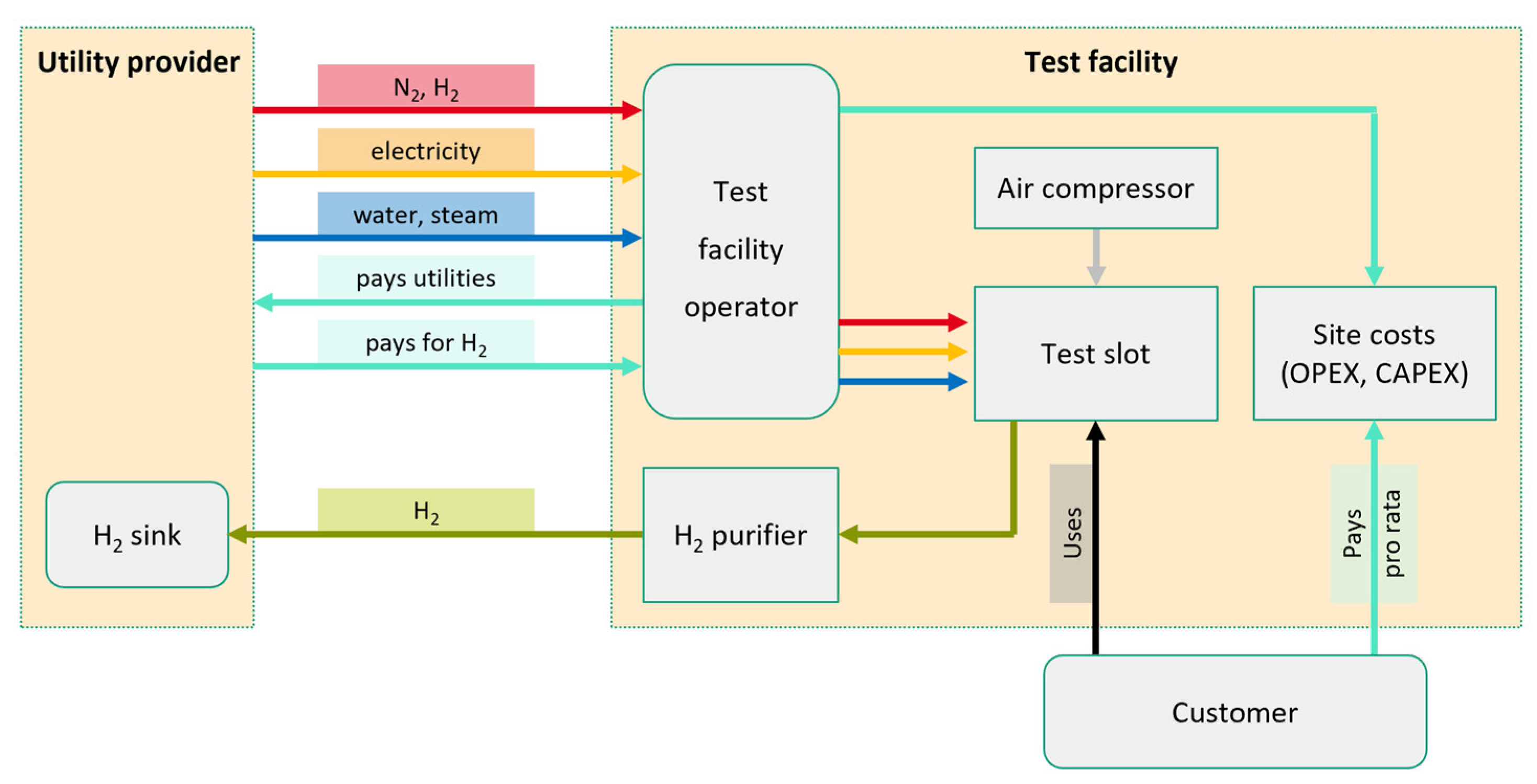
Figure 3 illustrates a potential business model for a large-scale test facility, in which the test facility operator purchases all utilities required for device testing and operating the site. The produced H
2 is purified and sold to offset some of the utility costs with the sale of the produced H
2. Test slots are offered to customers who pay for the provision of utilities, other OPEX including staff pro rata and a contribution to the CAPEX.
From the aforementioned numbers, it is clear that in the current global economic situation with inflated energy prices, large-scale electrolyser testing is expensive. This financial challenge can be alleviated with government funding for industrial research. Nevertheless, customers are likely to pay the costs for large-scale testing, provided there is a clear gain from the tests (see also
Section 6).
3.7. On-Site Testing
An alternative to developing dedicated facilities for testing electrolysers is performing tests on-site at existing industrial production sites or at customer sites. The advantage of this approach is the lowered CAPEX costs since the necessary periphery for operating electrolysers will largely be in place if the site already uses H2 from other sources or has been (re-)developed to accommodate an electrolyser in the future. The disadvantages, however, include possible limitations in the types of tests that can be performed (e.g., defined by the available measurement instrumentation), space constraints (tests must be accommodated in the existing layout, no tailoring is possible) and safety considerations (the presence of staff not related to testing, other processes and/or hazardous materials, ATEX zones, etc.). It also needs to be considered that production sites primarily focus on sustaining productivity; therefore, testing any early-stage prototypes with a potentially high failure rate may not be feasible due to the risk of causing disruptions to the production processes.
4. Outlook: Test Facilities for Large-Scale Photo-Electrochemistry and Photocatalysis
Besides EL, solar-driven water splitting has seen considerable improvements since the initial report by Fujishima and Honda [
32], especially in the past decade [
33]. The efficiencies and longevities of PEC [
34] and PC [
35] splitting of water into H
2 and O
2 have steadily increased, and scale-up studies are beginning to appear in the literature. The largest PEC device reported to date had an active area of 1.6 m
2 [
36]. Recent work by Domen reported a 100 m
2 PC solar water-splitting panel array [
7], which, considering the standard solar power irradiance and the device efficiency, corresponds to ~1 kW peak power. While the scale is still well below the MW range, it is clear that for practical implementation, scale-up to sizes comparable to electrolysers is the next logical step. Therefore, facilities for the large-scale testing of PEC and PC water-splitting processes will be needed in the near future. Testing these lower-TRL technologies is generally less predictable as the differences between individual devices are larger than in higher-TRL EL, e.g., the use of various additives [
37], solvents [
38], reactor geometries [
39], etc. In addition, full systems are not yet available, meaning that the test site must potentially provide additional balance-of-plant (BoP) components, e.g., water purification, cooling, circulation pumps, etc. The requirements and challenges discussed in
Section 3 for electrolytic water splitting largely apply also to test facilities for light-driven water splitting through PC and PEC and will be briefly discussed here in the same order.
The main difference between PC and PEC on the one hand and EL on the other hand is the requirement for a suitable light source for operation. While testing under natural sunlight is affordable and most relevant to real-world applications, the weather-dependent variability of natural sunlight availability gives rise to a low reproducibility that makes comparing different systems and operating parameters inaccurate. This can in part be circumvented by locating test facilities in areas with stable weather and frequent clear skies, e.g., the Plataforma Solar de Almeria, a site dedicated to testing solar–thermal processes, is situated in a desert. To obtain meaningful and reproducible performance data, artificial lighting is required with standardised spectral distribution, uniformity and intensity, similar to what is used in solar panel testing, i.e., meeting the AM1.5G definition in the ASTM G-173-03 standard (ISO 9845-1) [
40]. Large-scale solar simulators based on Xenon arc lamps for long-term operation are still rare and expensive to purchase and maintain; however, LED technology has recently lowered the CAPEX and OPEX for solar simulators [
41]. Any light source must be frequently calibrated to AM1.5G and the light intensity should be continuously monitored with a suitable meter.
The electrical power needed for the light-driven water-splitting PEC and PC processes is in principle lower than for EL since some (PEC) or all (PC) of the necessary energy is provided by photons. However, if these photons are generated using electrical lighting, much more electricity is required overall, since even the most efficient light sources do not have efficiencies above 25%. Thus, testing a 1 MW PEC or PC system with artificial lighting would require at least 4 MW plus the power for BoP components such as cooling, pumps, purification, etc. For PEC testing, provision of a large-scale potentiostat is required to control the applied cell voltage. Similar to the issues associated with sizing the MFM (
Section 3.3), a MW-scale potentiostat will have limits in terms of maximum current and voltage as well as resolution limits at low currents/voltages. A compromise between flexibility and accuracy may have to be made. PC testing is generally simpler since no electricity is involved in the water-splitting process; however, electricity is required for the BoP, particularly for water circulation and product purification. In addition, all the energy for the water splitting is provided in the form of light; therefore, significant additional electrical power supply is needed for the light source if artificial lighting is to be used.
The utilities for PC and PEC testing are no different from EL testing including water, inert gas and compressed air. PEC typically uses aqueous electrolytes such as Na2SO4 dissolved in DI water, and PC also generally requires water of DI purity. Regardless of the water-splitting process, the water consumption depends only on the H2 production; therefore, a 1 MW PEC or PC system will consume the same amount of water as a 1 MW EL system, i.e., 0.16 m3 h−1. PEC and PC usually operate close to ambient temperature unless they use concentrated solar light; therefore, cooling water demand is generally lower than with EL.
Similarly, the process analysis requirements resemble those of EL, meaning that H2 purity (O2 and moisture) and mass flow are the key parameters as well as utility consumption using suitably sized meters. However, since the quantities of H2 produced by PEC/PC are lower due to the currently smaller scale and lower efficiency, more sensitive analysis equipment may be required, e.g., gas chromatography, although this is expected to change as the scale increases with increasing TRL. To avoid issues with sampling explosive oxyhydrogen mixtures produced during PC, the product gas is commonly diluted with N2 below the explosion limits which, again, necessitates more sensitive gas analysis. In addition, the light intensity must be continuously monitored to correlate any performance fluctuations with variations in light intensity, especially if natural sunlight is used. PEC also requires monitoring of the applied voltage.
Considerations of a suitable H2 sink equally apply to PC and PEC, even though less H2 is produced. In addition, PEC and PC operate at atmospheric pressure, meaning a compression is required for any productive H2 sink. For PC, the produced oxyhydrogen must undergo a sophisticated and therefore expensive multi-stage purification process before any compression or use can be considered. It is therefore expected that the produced H2 is most likely to be vented or flared instead.
The safety aspects of PEC are similar to those of EL, with the addition of using large quantities of electrolytes which may be hazardous. It should also be considered that large-scale artificial lighting may cause additional safety-relevant hazards, such as UV radiation, ozone generation etc., which need to be managed. However, of major additional concern in PC is the formation of explosive atmospheres. Since PC water splitting occurs in a single-compartment reactor, oxyhydrogen gas, i.e., a highly explosive stoichiometric mixture of H2 and O2, is always formed inside the reactor during normal operation. Not only does this require stringent explosion safety measures, such as ATEX-1-rated equipment and special personal protective equipment (PPE), it also results in challenging permitting processes.
These additional safety concerns coupled with greater variability between different devices and the overall lower efficiency of PC and PEC make large-scale testing economically more challenging than EL testing. However, if natural sunlight is used, electricity consumption as the major cost contributor is substantially reduced whereby testing becomes more affordable at the expense of reproducibility.
Finally, it should be considered that due to the low power density of sunlight, namely, 1 kW m−2, the space requirement for testing a 1 MW solar water-splitting prototype is >1000 m2 compared to a 40-foot container with a footprint of 30 m2 for a 1 MW electrolyser.
5. The Hydrogen Lab Leuna
The Hydrogen Lab Leuna (HLL) is a test centre for hydrogen technologies on an industrial scale; its construction was completed in mid-2022. It is located inside the chemical industry site in Leuna (Germany), approximately 200 km south-west of the capital Berlin and consists of an outdoor testing area (
Figure 4) and a technical centre [
9].
The HLL is fully integrated with the utility supply network of the chemical industry site and operates 24/7 through remote operation. The outdoor testing area comprises four separate slots for testing electrolysers up to 5 MW of any type (PEM, SOEL, AEL). Each slot is around 150 m2 in size, sufficient to place at least two 40-foot containers plus ancillaries, and is equipped with an individual utility interface (IUI). The IUI supplies 6 kV medium voltage AC (800 A max.), N2 (20 Nm3 h−1), compressed air (10 Nm3 h−1), DI water (1.25 m3 h−1), process water (2.5 m3 h−1) and low-pressure steam (320 kg h−1) to the DUT and accepts H2 from the DUT (up to 1200 Nm3 h−1). Generated H2 and O2 are continuously analysed in a dedicated analysis system (H2 on O2, O2 and H2O in H2), and only H2 of sufficient purity is accepted into the IUI; O2 is vented. H2 is then purified onsite by deoxygenation and drying before being analysed again. Any H2 outside specification is automatically vented through a safety cold vent. H2 of sufficient purity is quantified and, following a conditioning step, is fed to the Linde H2 pipeline system, which supplies the local chemical industry. All piping is heated and insulated to cope with German winter weather (as low as −15 °C). All instruments and valves are ATEX-rated and connected to a programmable logic controller system, which is operated from the technical centre. In addition, the technical centre is designed for testing electrolysis components rather than complete systems. To this end, 50 kW test rigs for PEM stack testing will be installed. It also comprises a laboratory for the preparation and analysis of materials.
6. Conclusions
Large-scale green hydrogen production technologies are gaining momentum globally with a growing trend towards the MW scale. The provision of test facilities on that scale is a challenging process in its own right without blueprint or precedent and requires careful assessment of the requirements for the devices under testing with respect to utilities, monitoring and safety. Since there is no one-size-fits-all solution, flexibility has to be balanced against the investment costs, resulting in some degree of specialisation. For instance, it may be sufficient to focus on only one type of electrolyser (e.g., PEMEL) and a limited power range (0.5–1.5 MW), so that the differences between individual DUTs are smaller and fewer instruments are needed for product analysis. Choosing the right location for the test facility is also crucial. A chemical industry site facilitates the provision of utilities in sufficient quantities, the safe handling of large quantities of H2, and most importantly, the sale of H2 generated during testing, whereas a location near a wind farm or hydroelectric plant can lead to lower electricity costs. A sustainable business model is essential, with a cheap power supply and an existing productive H2 sink being essential for lowering the costs of testing as much as possible. Nevertheless, green hydrogen currently has a market value lower than its production costs in a research centre, meaning that testing is expensive. The costs are expected to decrease in the future as the demand for green hydrogen and hence the demand for testing will grow, so that test sites can operate at capacity. At the same time, the market value and volume for green hydrogen are expected to rise, facilitating cost recovery from the sale of H2. For the time being, however, government funding for industrial research is a promising means to lower the costs of testing, and thus support for the route to market. Even so, for a test facility to be viable and for customers to invest in testing, the information gained from the tests must outweigh their costs regardless of external funding. This is the case when testing increases the market value, e.g., through proving long-term performance in sophisticated accelerated stress testing or through providing the data for certification once international standards have been agreed. Since the green hydrogen market is still in its infancy and therefore subject to ongoing changes, test sites will need to undergo continuous adaption to meet future testing demands. However, the scale of testing is unlikely to grow indefinitely—the cost would be prohibitively high. Therefore, advanced testing protocols such as hybrid virtual/real testing with model-based extrapolation and accelerated stress testing will become key strategies in the future to maximise the information gained from minimal testing.


