Article

Novel Multi-Objective Optimal Design of a Shell-and-Tube Latent Heat Thermal Energy Storage Device

by
Francesco Fornarelli
1,2,*,
Lorenzo Dambrosio
3,
Sergio Mario Camporeale
3 and
Luigi Terlizzi
3
1
Department of Sciences of Agriculture, Food, Natural Resources and Engineering, University of Foggia, Via Napoli, 25, 71121 Foggia, Italy
2
Italian National Group of Mathematical Physics (GNFM) of the Italian National Institute of High Mathematics (INDAM), 00185 Rome, Italy
3
Department of Mechanics, Mathematics and Management (DMMM), Politecnico di Bari, Via Orabona, 4, 70125 Bari, Italy
*
Author to whom correspondence should be addressed.
Energies 2023, 16(4), 1882; https://doi.org/10.3390/en16041882
Submission received: 13 December 2022 / Revised: 14 January 2023 / Accepted: 10 February 2023 / Published: 14 February 2023
(This article belongs to the Special Issue Advanced Thermal Energy Storage Technologies)

Abstract

:
In the present paper a new multi-objective optimisation procedure for the design of a shell-and-tube Latent Heat Thermal Energy Storage (LHTES) is proposed. A simple arrangement of a cylindrical shell with multiple vertical tubes has been examined. The optimisation considers, as design variables, the number of tubes, the tube internal radius and the device height-to-diameter ratio, H / D , while the storage volume is kept constant. This analysis aims to detect the set of solutions which optimises the LHTES performances evaluated in terms of charging and discharging times and overall thermal energy capacity. To accomplish the multi-objectives optimal thermal storage design, a simplified mathematical model of the LHTES has been employed. This model can evaluate the prescribed performances for a given set of design variables. The proposed optimisation procedure evaluates new solutions along the most promising directions in the design variables domain, leading to a significant improvement in storage performances. The Design of the Experiment, together with the Pareto dominance relationship, gives a starting optimal solutions subset. The proposed optimisation procedure permits to enhance the starting optimal solutions subset letting approach the Pareto barrier. The paper shows that, at the end of the optimisation procedure, the designer can select the solutions on the Pareto barrier with the best performance and the corresponding design variables for each chosen solution. The proposed optimisation procedure will also allow for maintaining low computational costs due to the low number of the new design variables evaluated only in the promising directions.

1. Introduction

By now, the transition to renewable energy sources represent a key role in the development of net-zero carbon energy technologies also considering the national growth [1]. Indeed, the research on this topic is pushed by the international agreements to limit the worldwide climate change effects, but also by the single nation strategic energy policies together with social engagement [2,3]. In this scenario, Thermal Energy Storage (TES) systems can play an important role for increasing the expansion of renewable energy systems. TES devices can find applications not only in Concentrated Solar Power (CSP) plants but also in many applications such as cogeneration and waste heat recovery systems in case of time mismatch between heat generation and heat request by end users. Further applications are rising in the so-called power-to-heat for the storage and excess of renewable electric energy, and in Carnot thermal batteries as low cost alternative to electrochemical ones [4,5] or in heat recovery systems in heat exchanger technologies [6]. Thus, energy storage represents one of the essential requirements of such systems. The energy storage technology depends on the specific energy source and the energy conversion efficiency. In solar applications, the two main technologies include photovoltaic (PV) and concentrated solar power plants. The first is generally coupled with an electrochemical storage (batteries), whereas the latter needs thermal energy storage. Thermal storage devices can be classified into two main categories, sensible heat or latent heat, due to the storing material physical properties and the operating temperature range [7]. LHTES represents a very interesting technology since it can store a large quantity of energy per unit mass in a small temperature range [8,9]. The thermal energy is stored in a material that can change its phase across a certain temperature; thus, it is called phase change material (PCM) [10]. The shell-and-tube is a common latent heat storage configuration, where a closed vessel filled with storing material is crossed over by heat exchange tubes in which a heat transfer fluid (HTF) flows as tube bundle heat exchangers. The phase change and the convective heat transfer in LHTES affect the performance of the shell-and-tube storage device. The heat transfer is sensibly enhanced during the charging phase when the HTF generates convective flows in the PCM, while the discharging phase is less affected by convecting flows [11]. During the charging phase, the liquid phase of the PCM is in direct contact with the heated walls of the HTF tubes inducing a recirculation of the PCM due to the buoyancy [12]. Instead, during the discharging, the operative temperature of the HTF is below the melting point of the PCM; thus, the solid PCM surrounds the HTF tubes decreasing the buoyancy effects on the liquid PCM [13,14]. Often, the enhancement of the heat transfer in LHTES devices is studied and several technologies are proposed and analysed, such as fins addiction [15,16]. However, the cost of the device represents a key parameter in the design process; thus, the optimization of straight tube configuration is relevant. Hence, LHTES behaviour includes several physical phenomena influencing the performance of the device. The correlation between the design parameters and the objective variables represents an issue faced by scientists and engineers as widely reported by experimental results [17,18] and numerical simulations [19], where, due to the convective motion, even the device orientation play a key role [20]. Nevertheless, the performances, in terms of stored energy, charging and discharging time can vary significantly according to many design and working parameters. Moreover, even for a given LHTES category, like the shell-and-tube, the thermal storage performances can experience high variation depending on a specific geometry. The non-linearity of the problem and the intrinsic complexity of convective flows, together with the multiphase/phase-changing phenomena, represent a tough challenge. Thus, several scientists propose different analytical or empirical models to be able to predict the behaviour of LHTES devices avoiding time-consuming CFD numerical simulations or experimental campaigns [21,22]. Among these are analytical models that often consider the heat transferred to the PCM composed of three contributions: sensible heat of the solid phase, sensible heat of the liquid phase and the latent heat [23,24]. These methods give the complete time of melting and solidification of PCM, hence an average heat transfer rate, simplifying the performance analysis on such a complex physical problem [25,26]. Thus, there can be several thermal storage solutions that can fit a particular application depending on the performance objectives. This aspect is certainly true when dealing with a single objective optimisation where though two different solutions can meet a particular application request, they do not provide the same level of performance. Nonetheless, when the application requests involve more than a single aspect (multi-objective optimisation), the performance comparison of two different solutions can be a non-trivial and costly task. Therefore, to properly choose the most appropriate LHTES, it is necessary to solve a multi-objectives optimisation, detecting the Pareto optimal front. Usually, such multi-objective optimisation analysis can require high costs in terms of experimental/computational effort. For these reasons, the present article proposes a novel multi-objectives procedure, employing a limited number of design solutions exceeding the starting Design of the Experiment (DoE). Specifically, the present work proposes optimising an LHTES shell-and-tube device with respect to multi-objectives, taking into account theoretical correlations of the physical behaviour of the device in its charging and discharging phases. In particular, the performances to be optimised are the stored energy (maximization), the charging and discharging time (minimization), whereas the design variables are, for a cylindrical LHTES device geometry with a constant volume, the number of tubes, the tube internal radius and the device height to diameter ratio.

2. Theoretical Model

The present work considers a shell-and-tube LHTES device with a geometry consisting in a vertical cylinder vessel filled with PCM where a certain number of parallel tubes passes through it (Figure 1). HTF and PCM can exchange heat according to the local operating conditions. To predict the behaviour of the system, geometrical and operating parameters have to be correlated to the performance of the system. Indeed, the LHTES charging, when the PCM melts, follows a different trend with respect to the discharging phase, when the PCM cool down and solidifies. Fornarelli et al. [25] and Fornarelli and Camporeale [26] developed two different models for shell-and-tube LHTES device able to estimate the charging and discharging times of the LHTES:
t c = V H A α 1 N u ln T i n T w T s o l T w + 1 S t e + ln T l i q T w T f i n T w
t d = r i V H r m A α 1 N u ln T i n T w T l i q T w + 1 S t e 1 α r e 3 r i 3 3 r i r e 2 r i 2 2 + V A 1 α r e r i 2 ln T w T s o l T w T f i n
Equations (1) and (2) are related to a single tube, with a radius r i , surrounded by PCM which fills a cylindrical vessel of radius r e . V = π ( r e 2 r i 2 ) H and A = 2 π r i H are the PCM volume and the heat exchange area, respectively, related to a single module, where the thickness of the tubes is neglected. N u and S t e are the Nusselt and Stefan numbers of the heat exchange process. In detail, the Nusselt number has been estimated according to the Cebeci [27] correlation for the Prandtl number 0.01 < P r < 100 :
N u = 1 + B 32 . 0.5 R a P r 0.25 L 2 r i C N u f p
where the coefficients B and C are B = 0.0571322 + 0.20305 P r 0.43 , C = 0.9165 0.0043 P r 0.5 + 0.01333 ln P r + 0.0004809 / P r , respectively, and the term N u f p reads:
N u f p = 0.68 + 0.67 R a 0.25 1 . + 0.492 P r 9 . / 16 . 4 . / 9 .
The R a number is estimated for the charging and discharging phase as proposed by Fornarelli et al. [25] and Fornarelli and Camporeale [26], taking into account the operative conditions. The Stefan number, representing the ratio between the sensible and latent heat, is defined as S t e = c p ( T w T f u s ) Λ . The initial temperature, T i n , and the final temperature, T f i n , depend on the prescribed charging or discharging processes. T l i q and T s o l depend on the physical characteristics of the PCM. The approach of the models is modular, and its application to a tube bundle configuration is straightforward.
In the simplified charging and discharging models, the wall temperature at the outer surface of the tubes is assumed constant, T w , during the charging/discharging process. This assumption is based on the selected simplified models Fornarelli et al. [25], Fornarelli and Camporeale [26] that represents a simple tool to estimate the overall performance of LHTES, although the complex non-linear physical behaviour of such phenomenon. Nevertheless, this approximation is physically acceptable for high values of c p , H T F m ˙ H T F with respect to the heat power to limit the HTF temperature inlet outlet difference, where c p , H T F is the HTF heat capacity and m ˙ H T F is the HTF mass flow rate. As far as the optimisation analysis is concerned, the selected design variables are the number of tubes, m, the tube’s internal radius, r i , and the device height to diameter ratio, H / D . The heat exchange area, A, and the volume, V , filled by PCM, are evaluated from the design variables (see Figure 1). All the calculations have been carried out with constant total volume V = 0.46575 m 3 .
For the current analysis, seven different LHTES geometries have been taken into account; in Fornarelli and Dambrosio [28] all these geometries have been illustrated, including the analytical relation of the maximum tube radius for each geometry. The minimum tube radius depends on the height of the device and is given by the following relation.
r m i n = f ( P r ) H 2 G r 0.25
where
f ( P r ) = 11.474 + 48.92 P r 0.5 0.006085 P r 2
Equations (5) and (6) are related to the minimum internal radius of a vertically heated cylinder which can be treated as a vertical flat plate as the effects of curvature are negligible. P r and G r represent the Prandtl number and the Grashof number, respectively.
Here several discrete configurations have been considered according to the number of HTF tubes. In particular, the number of tubes spans from 3 to 37, where the 3, 4 and 5 tubes layout are shown in Figure 2, while 17 tubes layout is shown in Figure 3. Figure 4 show, by way of example, the geometries with 7, 19 and 37 tubes, respectively, adopting a honeycomb tube distribution. The honeycomb distribution presents several positive features, such as modularity, even pattern distribution of the thermal storage area cross-section, and high values for the ratio of total tube area to thermal storage area cross-section. Nevertheless, increasing the tube number, only a set of non-continuous integer numbers ( 7 , 19 , 37 , ) can be inserted in a honeycomb pattern. As it will be shown in the next sections, since the tube number represents a design variable, its non-continuous nature can affect the multi-objective optimisation. The PCM filling the cylindrical vessel can be divided into two main zones: the PCM surrounding the HTF tubes, as considered in the charging and discharging models Equations (1) and (2) (white area), and the shaded PCM area, not included in the prediction model. Then, to consider the influence of the PCM mass not included in the model, the charging and discharging time have been increased linearly due to the additional shaded PCM mass.
In the present work, a binary mixture of 60 % w t of N a N O 3 and 40 % w t of K N O 3 have been considered as PCM whose physical characteristics are reported in Table 1. The analytical prediction models were validated with CFD and experimental data related to this particular PCM being used as storage material in several CSP applications [7,13].
The setup of the charging phase is related to the temperature according to the initial and the boundary conditions: in particular, for the charging phase, the initial temperature of the PCM is kept below the phase change temperature T i n = 423.15 K, the wall temperature T w = 523.15 K and the final temperature T f i n = 0.994 T w . The discharging phase is characterised by the following initial and boundary conditions: T i n = 523.15 K, T f i n = 1.006 T w . Under such assumptions, the heat released during the discharging phase is equal to the heat stored during the charging phase [25,26].

3. Multi-Objective Optimisation

Many authors, for example, [29], described in detail the theory of the multi-objective optimisation analysis and the concept of non-dominated solutions, which constitute the Pareto frontier. Let X = [ X 1 , X 2 , , X N ] and Y = [ Y 1 , Y 2 , , Y M ] be the design variable input and the corresponding performance variable output, respectively. For the sake of simplicity, let us assume that all the performance components ( Y i , i = 1 , , M ) aim at minimization (the extension to the maximisation case is straightforward). Let X 1 and X 2 be two different design variables which correspond to the performance variables Y 1 and Y 2 , respectively. At this point, if
i 1 , , M Y i 1 < Y i 2
then the solution X 2 is stated as dominated by solution X 1 . Otherwise, if
i 1 , , M Y i 1 > Y i 2
then the solution X 2 is stated as non dominated by solution X 1 . Finally, if
i , j 1 , , M i j Y i 1 < Y i 2 , Y j 1 > Y j 2
then the two solutions do not dominate each other. Applying Equations (7)–(9) to all the possible solutions, it is possible to isolate the set of all non-dominated solutions that represents the Pareto Frontier. Specifically, Equations (7) and (8) serve to differentiate dominated solutions from non dominated ones. On the other hand, Equation (9) relates two non dominated solutions and, therefore, must hold among the Pareto Frontier solutions. Nevertheless, performing the dominant relations (7)–(9) is not an efficient way to reveal the Pareto Frontier. From this perspective, the Design of Experiment [29,30], (DoE), represents an effective strategy for evaluating the output performances Y i varying the independent input variables X i according to a prescribed scheme, for example, a Carthesian (equally-spaced) scheme [31,32].
It is worth noting that the subset of X i solutions obtained by carrying out the dominance relations (7)–(9) on the DoE output performances Y i constitutes only a 1st level Pareto Frontier. To refine these 1st level Pareto Frontier solutions one needs to detect, in the design variable space, which directions provide further improvements in terms of objective functions. A possible way to accomplish this task is first to detect a subset of solutions X i , indicated in the following as sub-optimal solutions, whose performances are slightly lower than those of the 1st level Pareto Frontier solutions. Connecting each sub-optimal solution with the closest solutions of the 1st level Pareto Frontier it is possible to evaluate, in the design variable space, the directions which allowed the sub-optimal solutions to evolve to the 1st level Pareto Frontier solutions. A straightforward method to isolate the subset of sub-optimal solutions is to take out all the non-dominated solutions from the initial DoE and then executing the non-dominated relation (7)–(9) to the reduced DoE solutions. Finally, with reference to the design variables domain, for each solution of the sub-optimal set the three closest optimal solutions (1st level Pareto Frontier) have been taken into account selecting, then, only the direction which exhibits the best performance improvement. In this way, the most promising directions, along which at least one of the objective functions enhances, have been defined.
New optimal solutions have been isolated by imposing the dominance relationship (7)–(9) on the whole set consisting of both the solutions of the first DoE and those corresponding to the new design variables assigned in the promising directions. Of course this process can be iterated, and it will be stopped when the performance variable improvements are quite small from one iteration to the next.

4. Results

In this section, the results of the multi-objective optimisation analysis will be presented. The three objective functions are represented by the thermal storage charging time, t c , the stored heat by the thermal storage (that depends on the total volume V filled by PCM), Q, and the discharging time, t d . On the other hand, the design variables are given by the number of modules, m, the tubes internal radius, r i , and the device height-to-diameter ratio, H / D . In particular, the number of modules, m, varies among the seven geometries mentioned in the previous section; the tubes internal radius, r i , ranges from the minimum value provided by Equation (5) (flat plate condition) to the maximal value which represents the tangential condition. The optimisation analysis aims to investigate the design variables domain to detect all the solutions which minimise both the charging and discharging time and maximise the stored heat. Figure 5 illustrates the starting DoE in the design variable domain, whose “pyramid” shape is due to the geometrical imposed constraints. On the other hand, Figure 6 shows the corresponding results in terms of the objective functions in the performance space.
As stated in Section 3, all the objective functions are independent and, therefore, there is no unique solution that optimises all the objectives simultaneously. This means that to isolate all the non-dominated solutions (Pareto frontier), it is necessary to apply the dominance relations (7)–(9) to all the DoE solution points (Figure 5 and Figure 6). Of course, since in the present optimisation problem, not all the objective functions have to be minimised, the dominance relations (7)–(9) need to be accordingly modified. Figure 7 illustrates the subsets of optimal (red circles) and sub-optimal (blu circles) solutions; moreover, in the same figure, it is possible to observe the evolution from sub-optimal solutions subset to the optimal one. For this reason, the sub-optimal solutions provide a stricter criterion able to identify preferential directions in which the storage performances improve.
At first, for each sub-optimal solution, the three closest optimal points have been isolated; afterwards, the direction connecting sub-optimal to optimal points along which at least one of the objective functions enhances the most has been considered in the design variables domain. For such a reason, these directions have been reported to be promising, in the sense that the solution is likely to be further improved. Figure 7 and Figure 8 show the result of this process in performance and design, respectively, due to the one-to-one correspondence between the two spaces. In particular, Figure 8 includes the directions along which at least one specific performance improves the most, where the performance enhancements have been indicated with Δ Q , Δ t r e f and Δ t d i s , for the stored energy, the charging time and discharging time, respectively. Figure 9 shows a single promising direction (design variables domain) in which, not only the sub-optimal and the optimal points are indicated (blue and red circles, respectively), but also the new design solutions (black circles) have been specified. Considering all promising directions, a new family of design variables have been defined and, through the LHTES model, described in Section 2, the corresponding performances have been evaluated.
New optimal solutions have been isolated by imposing the dominance relationship (7)–(9) on the whole set consisting of both the starting DoE and those corresponding to the new design variables assigned in the promising directions. Figure 10 shows the results of the optimisation in the performance space. For the sake of clarity, Figure 11 and Figure 12 illustrate the same results in a bi-dimensional domain, in charging time—stored heat plane and in charging time—discharging time plane, respectively.
Although the optimisation process has been carried out only once, a significant enhancement of the starting non dominated solutions subset has been experienced, especially for the discharging time objective function. Of course, further iterations would improve the optimal solutions subset, but this would lead to minor improvements in terms of storage performances.
Finally, Figure 13 reports the new optimal points in the design variables domain. This is a very useful result for the LHTES design since it is quite evident that the described optimization procedure yields a significant reduction in terms of design points compared to the starting ones. In particular, the best performances are achieved with low values of the radius with a high concentration of optimal points near the flat plate condition. From a physical point of view, this conclusion is confirmed considering that small values the tubes internal radius allows the LHTES to contain higher PCM mass and consequently to increase the stored energy. On the other hand, high values of the H/D ratio lead to increase the heat exchanging surface which in turns determines a reduction of the charging and discharging times.
In addition, as far as the module number is concerned, it is noteworthy that the configurations with 17, 19 and 37 modules offer a wider field of application. This is mainly due to the honeycomb distributions, which provide good characteristics such as modularity, even pattern distribution of the thermal storage area cross-section, and high values for the ratio of total tube area to thermal storage area cross-section.
The present multi-objective optimisation analysis can be very useful for thermal storage device design problems. To illustrate this aspect, let us consider, as an example, to design a shell-and-tube LHTES device featured by stored energy ranging from 1.8 × 10 5 to 1.9 × 10 5 kJ; from the Pareto frontier, reported in Figure 10, it is quite straightforward to isolate the optimal solutions that meet the stored energy constraint, as reported in Figure 14.
For the sake of completeness, Table 2 outlines the main characteristics of the shell-and-tube LHTES devices that fulfil the prescribed stored energy range; of course, it is easy to extend this procedure to other design problems even with more than a single constraint in both the performance and design domains.

5. Conclusions

The present paper dealt with a new multi-objective optimisation procedure for the design of a shell-and-tube Latent Heat Thermal Energy Storage (LHTES). Thanks to the optimisation process, a set of solutions which improves the LHTES performance in terms of charging and discharging times and overall thermal energy capacity have been defined. The design variables considered for the optimisation process are represented by the number of tubes, the tube’s internal radius and the device height to diameter ratio, H / D , while the storage volume has been kept constant. To carry out such an optimisation analysis, several sub-tasks have been achieved:
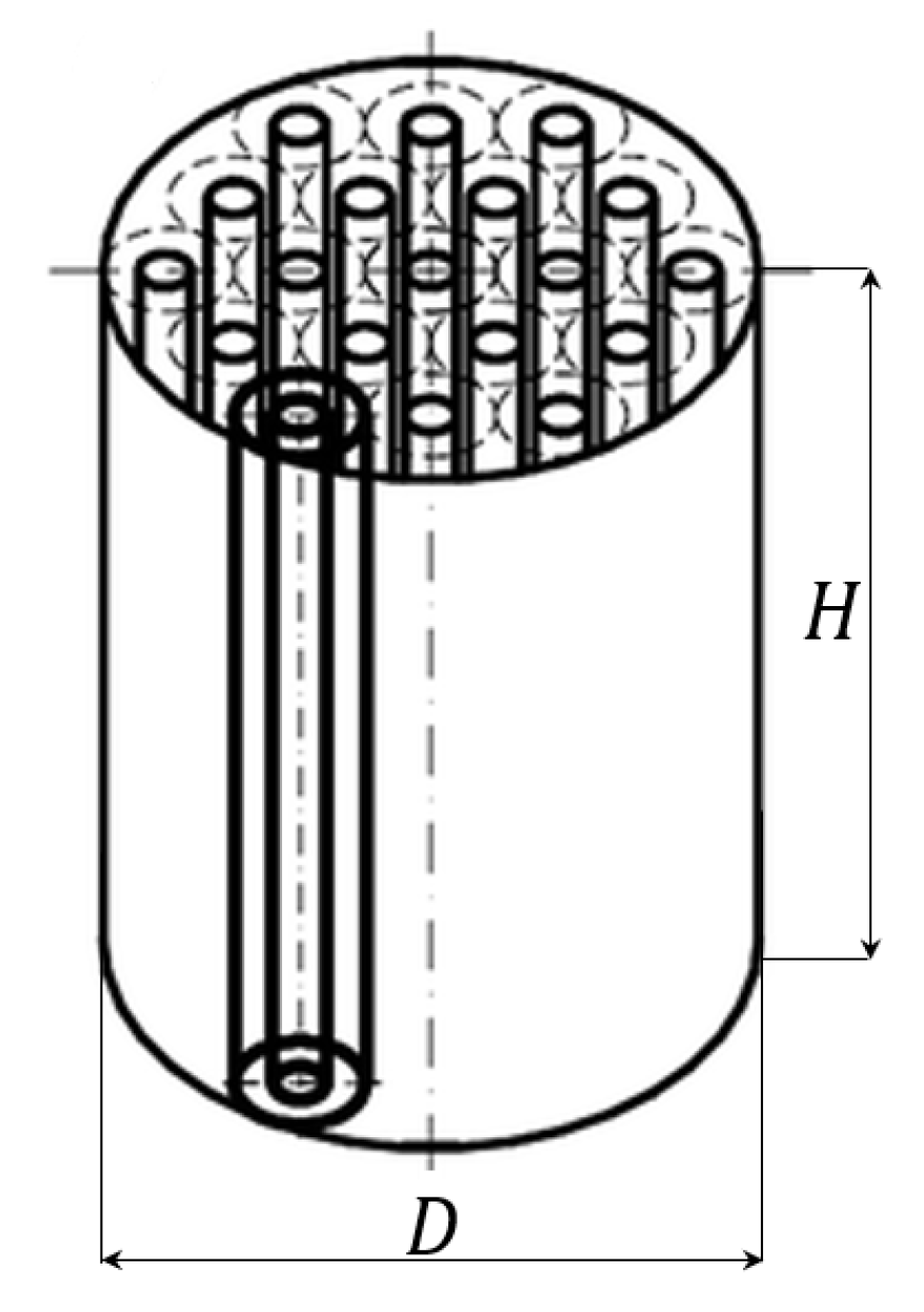
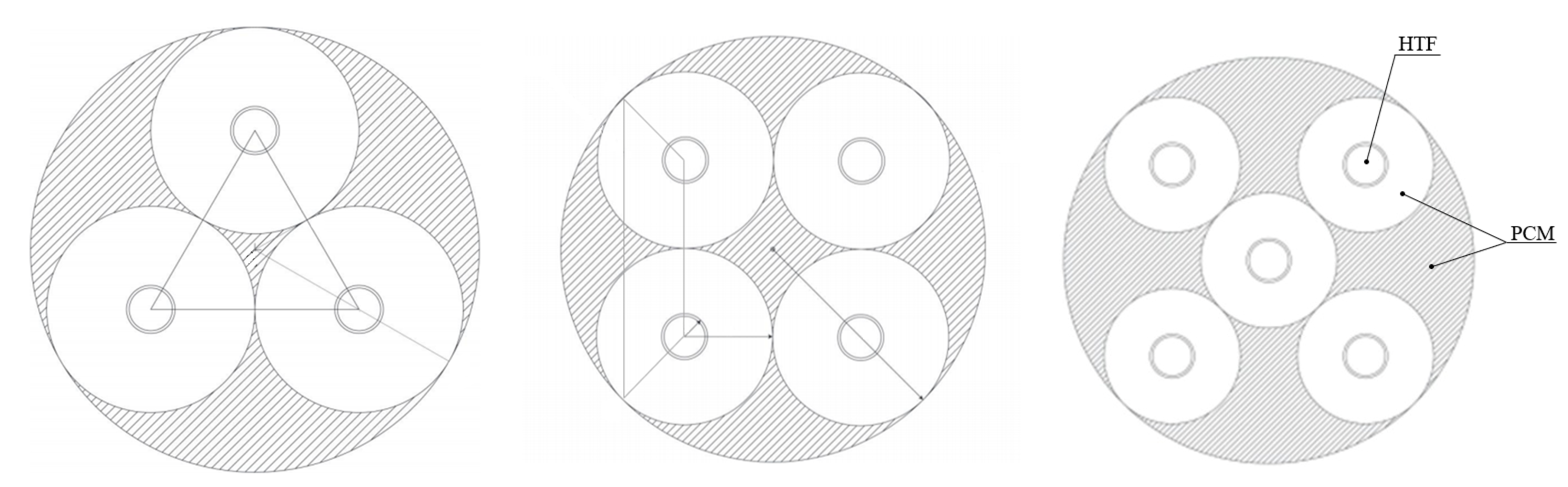
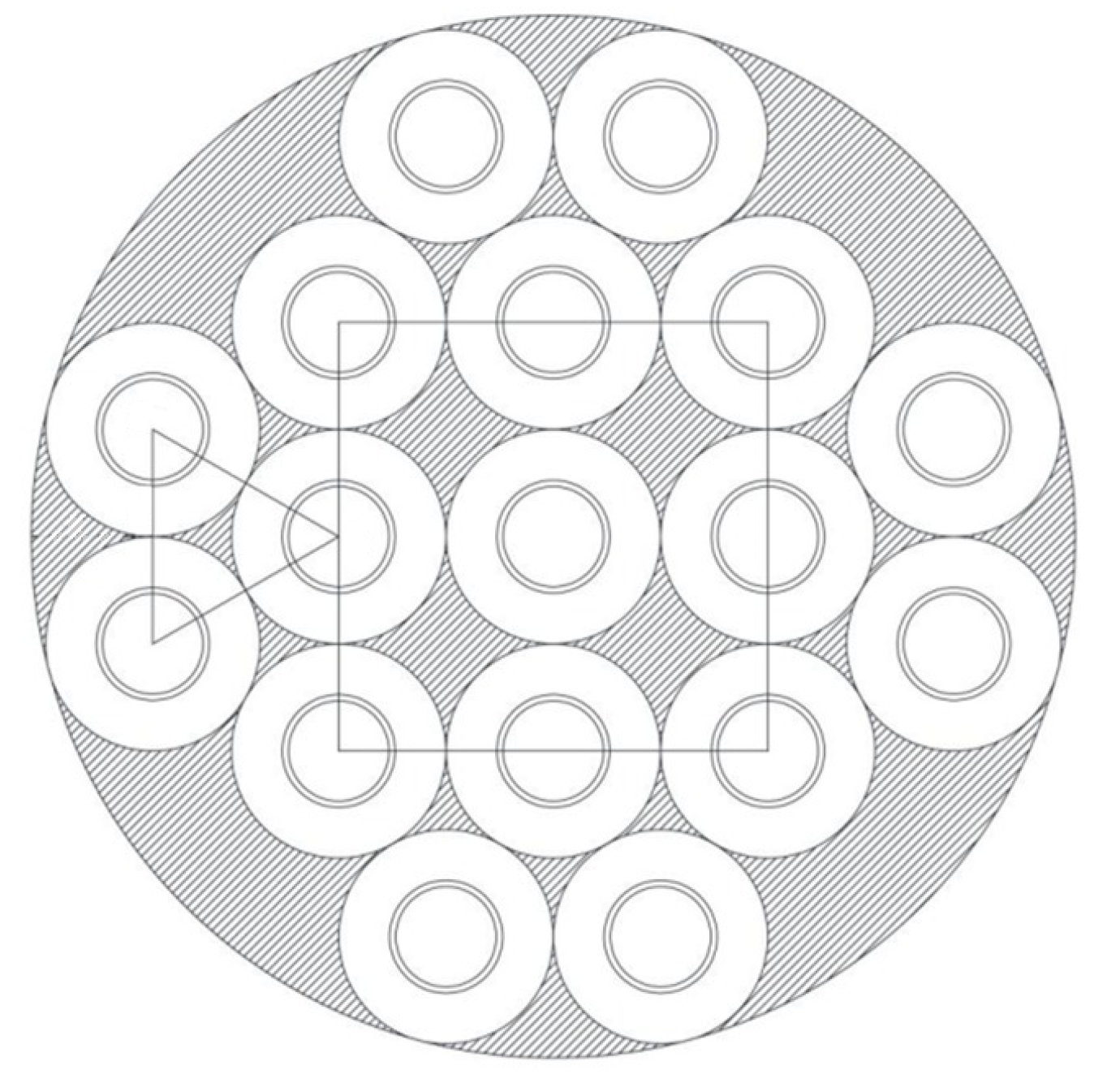
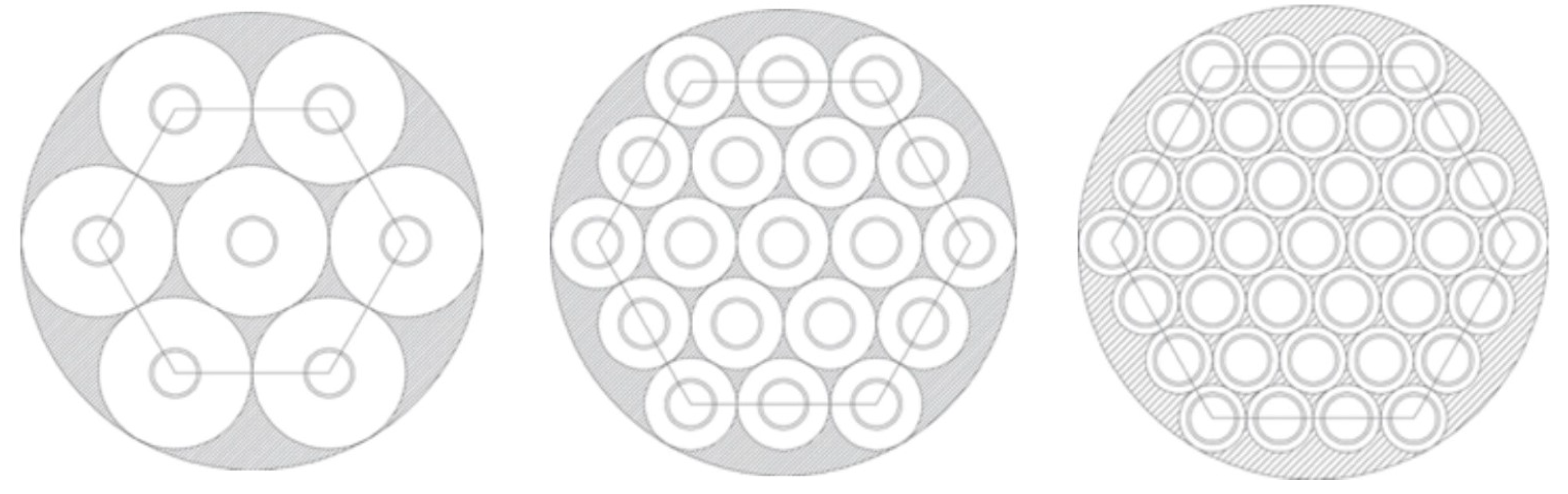
  • A simplified mathematical model of the LHTES has been employed: starting from the simplified model of a cylindrical shell-and-tube geometry, new constraints have been included to extend the heat exchange equations to the multitube system.
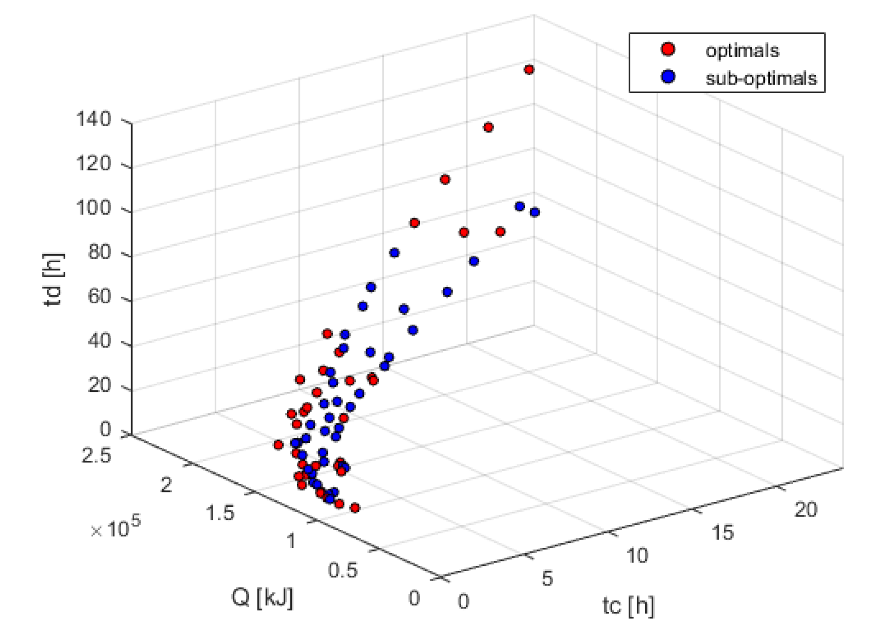
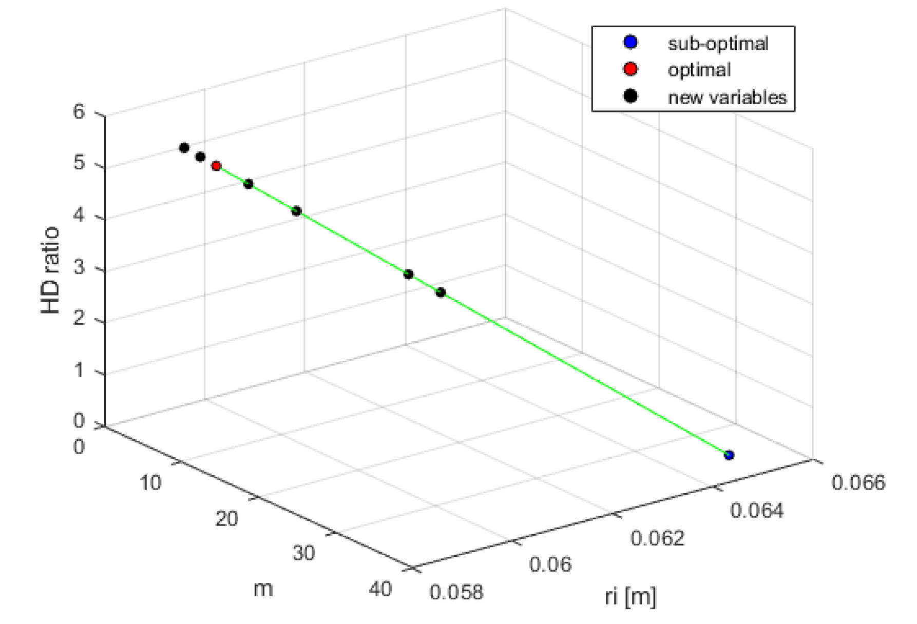
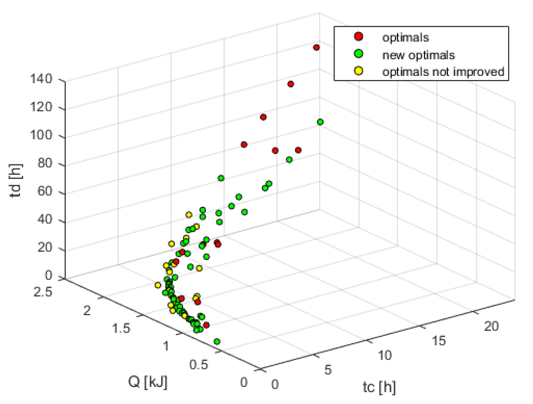
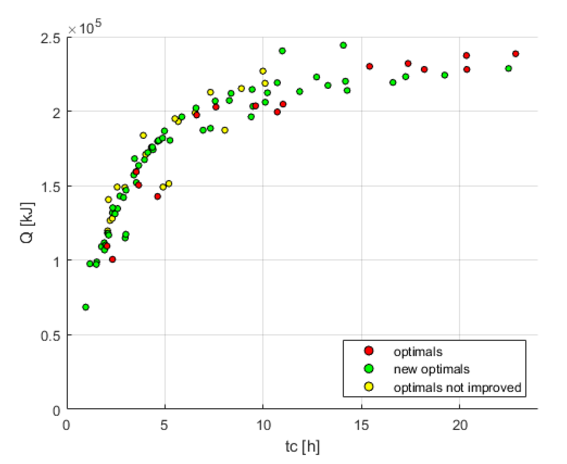
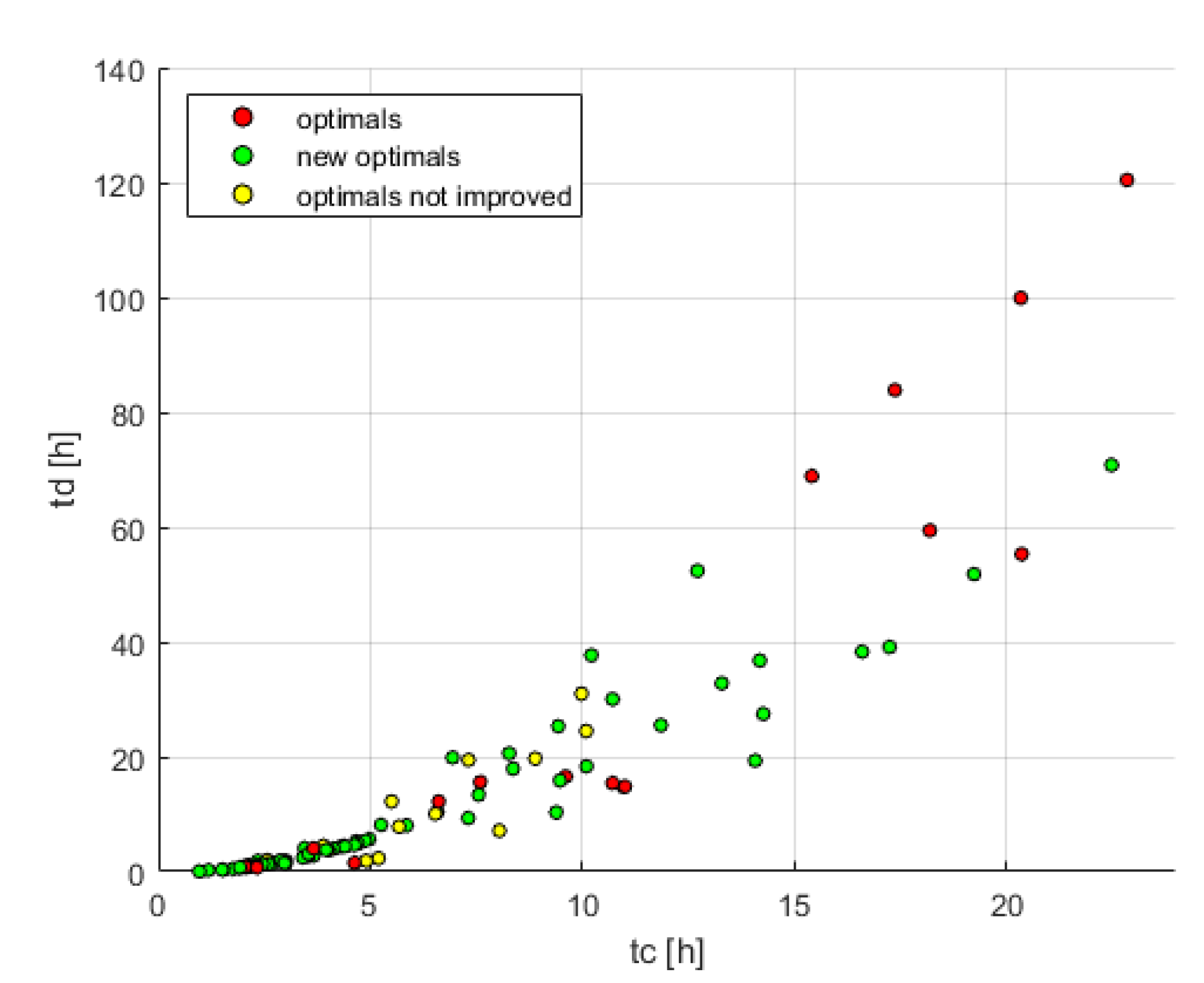
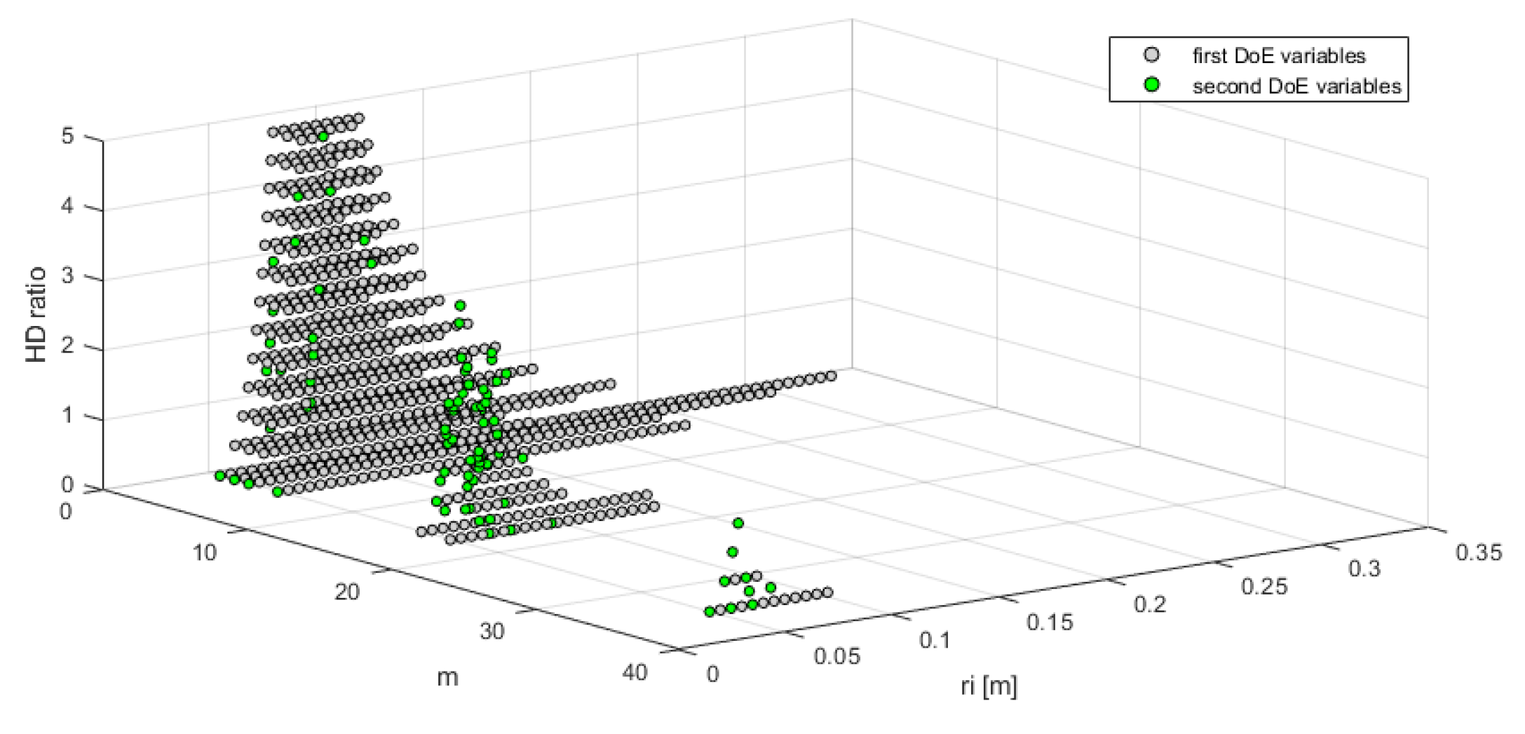
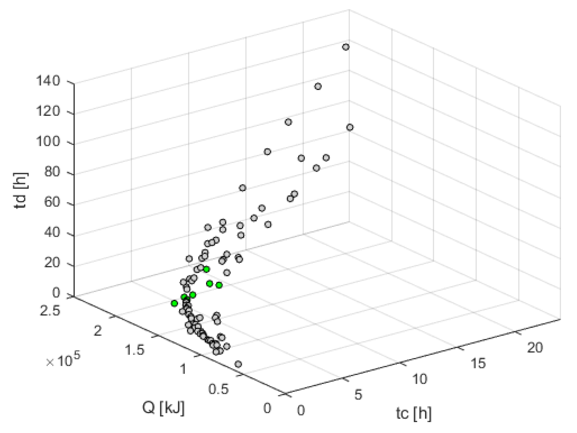
  • The Design of the Experiment obtained thanks to the Pareto dominance relationship has provided an initial optimal solutions subset.
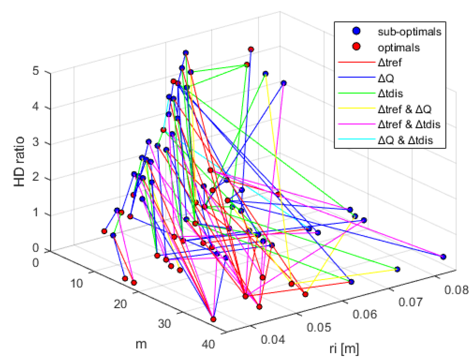
  • The proposed optimisation procedure, starting from the initial optimal solutions subset has defined new solutions along the most promising directions in the design variables domain, yielding a significant improvement in the storage performances.
The results obtained are very encouraging not only as regards the increase in performance, but also for the low calculation costs considering the low number of the new design variables evaluated only in the promising directions. Such results can be helpful for thermal storage device design problems. The figures reported in Section 4 illustrate this aspect, and it is quite straightforward to isolate the optimal solutions that meet the design constraint. Moreover, the proposed optimisation methodology appears robust and can be extended to additional design parameters, such ad the PCM composition and objectives, such as the minimization of the LHTES cost to detect the best candidate solutions for the multitube LHTES design.

Author Contributions

Conceptualization, F.F. and L.D.; methodology, F.F., L.D. and S.M.C.; software, F.F., L.D. and L.T.; investigation, F.F., L.D. and L.T.; formal analysis, F.F., L.D. and S.M.C.; writing—original draft preparation, F.F., L.D., L.T. and S.M.C.; writing—review and editing, F.F., L.D., L.T. and S.M.C.; supervision, F.F. and L.D. All authors have read and agreed to the published version of the manuscript.

Funding

This work was financially supported by MIUR-“Ministero dell’Istruzione dell’Università e della Ricerca” under the Programmes: “Department of Excellence” Legge 232/2016 (Grant No. CUP-D94I18000260001).

Data Availability Statement

Not applicable.

Conflicts of Interest

The authors declare that they have no known competing financial interests or personal relationships that could have appeared to influence the work reported in this paper.

Nomenclature

Subscript
cCharge
dDischarge
i n Initial
f i n Final
wWall
s o l Solidus
l i q Liquidus
iInternal
eExternal
Superscript
¯ Mean
Greek letters
ρ Density
α Thermal diffusivity
Symbols
TTemperature
tTime
QStored heat
rTubes radius
DDevice diameter
HDevice height
V P C M volume
A Heat exchange area
N u Nusselt number
S t e Stefan number
P r Prandtl number
G r Grashof number

Abbreviations

LHTESLatent heat thermal energy storage
PCMPhase change material
CSPConcentrated solar power
PVPhotovoltaic
HTFHeat transfer fluid
DoEDesign of Experiment

References

  1. Marques, A.C.; Fuinhas, J.A. Is renewable energy effective in promoting growth? Energy Policy 2012, 46, 434–442. [Google Scholar] [CrossRef]
  2. Baz, K.; Cheng, J.; Xu, D.; Abbas, K.; Ali, I.; Ali, H.; Fang, C. Asymmetric impact of fossil fuel and renewable energy consumption on economic growth: A nonlinear technique. Energy 2021, 226, 120357. [Google Scholar] [CrossRef]
  3. Hawes, R.; Nowlin, M.C. Climate science or politics? Disentangling the roles of citizen beliefs and support for energy in the United States. Energy Res. Soc. Sci. 2022, 85, 102419. [Google Scholar] [CrossRef]
  4. Dumont, O.; Frate, G.F.; Pillai, A.; Lecompte, S.; De paepe, M.; Lemort, V. Carnot battery technology: A state-of-the-art review. J. Energy Storage 2020, 32, 101756. [Google Scholar] [CrossRef]
  5. Liang, T.; Vecchi, A.; Knobloch, K.; Sciacovelli, A.; Engelbrecht, K.; Li, Y.; Ding, Y. Key components for Carnot Battery: Technology review, technical barriers and selection criteria. Renew. Sustain. Energy Rev. 2022, 163, 112478. [Google Scholar] [CrossRef]
  6. Koç, A.; Yağlı, H.; Bilgic, H.H.; Koç, Y.; Özdemir, A. Performance analysis of a novel organic fluid filled regenerative heat exchanger used heat recovery ventilation (OHeX-HRV) system. Sustain. Energy Technol. Assess. 2020, 41, 100787. [Google Scholar] [CrossRef]
  7. Fornarelli, F.; Camporeale, S.; Fortunato, B.; Torresi, M.; Oresta, P.; Magliocchetti, L.; Miliozzi, A.; Santo, G. CFD analysis of melting process in a shell-and-tube latent heat storage for concentrated solar power plants. Appl. Energy 2016, 164, 711–722. [Google Scholar] [CrossRef]
  8. Mourad, A.; Aissa, A.; Said, Z.; Younis, O.; Iqbal, M.; Alazzam, A. Recent advances on the applications of phase change materials for solar collectors, practical limitations, and challenges: A critical review. J. Energy Storage 2022, 49, 104186. [Google Scholar] [CrossRef]
  9. Crespo, A.; Barreneche, C.; Ibarra, M.; Platzer, W. Latent thermal energy storage for solar process heat applications at medium-high temperatures—A review. Solar Energy 2019, 192, 3–34. [Google Scholar] [CrossRef]
  10. Cárdenas, B.; León, N. High temperature latent heat thermal energy storage: Phase change materials, design considerations and performance enhancement techniques. Renew. Sustain. Energy Rev. 2013, 27, 724–737. [Google Scholar] [CrossRef]
  11. Sodhi, G.S.; Vigneshwaran, K.; Muthukumar, P. Experimental investigations of high-temperature shell and multi-tube latent heat storage system. Appl. Therm. Eng. 2021, 198, 117491. [Google Scholar] [CrossRef]
  12. Fornarelli, F.; Camporeale, S.M.; Fortunato, B. Convective Effects in a Latent Heat Thermal Energy Storage. Heat Transf. Eng. 2019, 42, 1–22. [Google Scholar] [CrossRef]
  13. Fornarelli, F.; Ceglie, V.; Fortunato, B.; Camporeale, S.; Torresi, M.; Oresta, P.; Miliozzi, A. Numerical simulation of a complete charging-discharging phase of a shell and tube thermal energy storage with phase change material. Energy Procedia 2017, 126, 501–508. [Google Scholar] [CrossRef]
  14. Fornarelli, F.; Torresi, M.; Oresta, P.; Dambrosio, L.; Miliozzi, A.; Camporeale, S. Discharging shape influence on the performance of a latent heat thermal energy storage. AIP Conf. Proc. 2019, 2191, 020079. [Google Scholar] [CrossRef]
  15. Ge, R.; Li, Q.; Li, C.; Liu, Q. Evaluation of different melting performance enhancement structures in a shell-and-tube latent heat thermal energy storage system. Renew. Energy 2022, 187, 829–843. [Google Scholar] [CrossRef]
  16. Pizzolato, A.; Sharma, A.; Ge, R.; Maute, K.; Verda, V.; Sciacovelli, A. Maximization of performance in multi-tube latent heat storage—Optimization of fins topology, effect of materials selection and flow arrangements. Energy 2020, 203, 114797. [Google Scholar] [CrossRef]
  17. Beyne, W.; Couvreur, K.; T’Jollyn, I.; Lecompte, S.; De Paepe, M. Estimating the state of charge in a latent thermal energy storage heat exchanger based on inlet/outlet and surface measurements. Appl. Therm. Eng. 2022, 201, 117806. [Google Scholar] [CrossRef]
  18. Peng, B.; Huang, G.; Wang, P.; Li, W.; Chang, W.; Ma, J.; Li, C. Effects of thermal conductivity and density on phase change materials-based thermal energy storage systems. Energy 2019, 172, 580–591. [Google Scholar] [CrossRef]
  19. Trp, A.; Lenic, K.; Frankovic, B. Analysis of the influence of operating conditions and geometric parameters on heat transfer in water-paraffin shell-and-tube latent thermal energy storage unit. Appl. Therm. Eng. 2006, 26, 1830–1839. [Google Scholar] [CrossRef]
  20. Kamkari, B.; Shokouhmand, H.; Bruno, F. Experimental investigation of the effect of inclination angle on convection-driven melting of phase change material in a rectangular enclosure. Int. J. Heat Mass Transf. 2014, 72, 186–200. [Google Scholar] [CrossRef]
  21. Couvreur, K.; Beyne, W.; Tassenoy, R.; Lecompte, S.; De Paepe, M. Characterization of a latent thermal energy storage heat exchanger using a charging time energy fraction method with a heat loss model. Appl. Therm. Eng. 2023, 219, 119526. [Google Scholar] [CrossRef]
  22. Tarragona, J. Experimental analysis of a latent thermal energy storage system enhanced with metal foam. J. Storage Mater. 2021, 41, 102860. [Google Scholar] [CrossRef]
  23. Duan, J.; Xiong, Y.; Yang, D. On the Melting Process of the Phase Change Material in Horizontal Rectangular Enclosures. Energies 2019, 12, 3100. [Google Scholar] [CrossRef]
  24. Diarce, G.; Campos-Celador; Sala, J.M.; García-Romero, A. A novel correlation for the direct determination of the discharging time of plate-based latent heat thermal energy storage systems. Appl. Therm. Eng. 2018, 129, 521–534. [Google Scholar] [CrossRef]
  25. Fornarelli, F.; Camporeale, S.; Fortunato, B. Simplified theoretical model to predict the melting time of a shell-and-tube LHTES. Appl. Therm. Eng. 2019, 153, 51–57. [Google Scholar] [CrossRef]
  26. Fornarelli, F.; Camporeale, S. Simplified prediction model of the discharging time of a shell-and-tube LHTES. Appl. Therm. Eng. 2020, 179, 115709. [Google Scholar] [CrossRef]
  27. Cebeci, T. Laminar-free-convective-heat transfer from the outer surface of a vertical circular cylinder. In Proceedings of the 5th International Heat Transfer Conference, Tokyo, Japan, 3–7 September 1974; Volume 3, pp. 15–19. [Google Scholar]
  28. Fornarelli, F.; Dambrosio, L. Multi-objective sensitivity analysis of shell-and-tube LHTES performance. E3S Web Conf. 2021, 312, 01006. [Google Scholar] [CrossRef]
  29. Periaux, J.; Gonzalez, L.; Lee, D. Evolutionary Optimization and Game Strategies for Advanced Multi-Disciplinary Design; Springer: Berlin/Heidelberg, Germany, 2015; Volume 75. [Google Scholar] [CrossRef]
  30. Caramia, M.; Dell’Olmo, P. Multi-Objective Management in Freight Logistics: Increasing Capacity, Service Level, Sustainability, and Safety with Optimization Algorithms; Springer: London, UK, 2020. [Google Scholar] [CrossRef]
  31. Dambrosio, L.; Fortunato, B.; Marco, T.; Camporeale, S.; Fornarelli, F. Performance optimization of a gas-steam combined power plant partially fed with syngas derived from pomace. Energy Procedia 2017, 126, 533–540. [Google Scholar] [CrossRef]
  32. Dambrosio, L.; Micera, R.; Fortunato, B.; Marco, T. Multi-Objective Optimization of a Combined Power Plant Fueled by Syngas Produced in a Downdraft Gasifier. Energy Procedia 2018, 148, 1050–1057. [Google Scholar] [CrossRef]
Figure 1. Geometry shell-and-tube LHTES device.
Energies 16 01882 g001
Figure 2. Top view of the LHTES shell-and-tube devices, from the left to the right, of 3, 4 and 5 modules.
Energies 16 01882 g002
Figure 3. Top view of the LHTES shell-and-tube device with 17 modules.
Energies 16 01882 g003
Figure 4. Top view of the LHTES shell-and-tube devices with honeycomb tube distribution, from the left to the right, of 7, 19 and 37 modules.
Energies 16 01882 g004
Figure 5. Starting DoE in the design variable domain.
Energies 16 01882 g005
Figure 6. Starting DoE in the performances domain.
Energies 16 01882 g006
Figure 7. Optimal and sub-optimal solutions in the performances domain.
Energies 16 01882 g007
Figure 8. Optimal and sub-optimal solutions in the design variable domain.
Energies 16 01882 g008
Figure 9. Promising direction and new design solutions in the performance domain.
Energies 16 01882 g009
Figure 10. New optimal solutions isolated by imposing the dominance relationship.
Energies 16 01882 g010
Figure 11. New optimal solutions in charging time—stored heat domain.
Energies 16 01882 g011
Figure 12. New optimal solutions in charging time—discharging time domain.
Energies 16 01882 g012
Figure 13. New optimal solutions in the design variable domain.
Energies 16 01882 g013
Figure 14. Optimal solutions that meet the stored energy constraint.
Energies 16 01882 g014
Table 1. Physical properties of the PCM.
PropertiesValues
Density ρ P C M = 1994 kg m 3
Thermal Expansion Coefficient β P C M = 3.18861 × 10 4 1 K
Specific Heat c p , P C M = 1626 J kg · K
Conductivity k P C M = 0.4886 W m · K
Dynamic Viscosity μ P C M = 7.008 × 10 3 kg m · s
Solidus Temperature T s o l = 493.03 K
Liquidus Temperature T l i q = 517.29 K
Latent Heat Λ = 1.10 × 10 5 J kg
Table 2. Optimal shell-and-tube LHTES solution.
Q [kJ] t c [h] t d [h]m r i [m] H / D
1.8036 × 10 5 4.70 4.87 17 0.0462 1.53
1.8037 × 10 5 4.67 5.26 19 0.0480 1.16
1.8046 × 10 5 5.25 8.16 19 0.0598 0.60
1.8200 × 10 5 4.88 5.38 17 0.0471 1.40
1.8379 × 10 5 3.90 4.51 37 0.0418 0.60
1.8676 × 10 5 4.97 5.68 19 0.0441 1.29
1.8725 × 10 5 6.94 19.88 19 0.0818 0.20
1.8728 × 10 5 8.05 7.14 5 0.0578 4.20
1.8854 × 10 5 7.31 9.34 7 0.0541 3.00
Disclaimer/Publisher’s Note: The statements, opinions and data contained in all publications are solely those of the individual author(s) and contributor(s) and not of MDPI and/or the editor(s). MDPI and/or the editor(s) disclaim responsibility for any injury to people or property resulting from any ideas, methods, instructions or products referred to in the content.

