1. Introduction
The study of heat transfer in falling films of liquids and their mixtures is important for improving the efficiency of numerous systems using film flows—from natural gas liquefaction (LNG) plants, distillation plants, and absorption apparatuses, as well as evaporative equipment of the chemical and food industries—to desalination plants and electronic equipment cooling systems (e.g., spray and falling-film cooling system [
1]). The intensification of heat transfer at boiling and evaporation of liquids by structuring the heat-generating surface is a key method for increasing the efficiency of both traditional [
2,
3,
4,
5] and renewable [
6] energy systems. Despite the fact that studies on heat transfer enhancement have been actively carried out since the middle of the last century, their relevance at the current pace of technology development is only increasing. Among various types of structured coatings (including capillary-porous), wire mesh coverings—which can be attributed to the simplest porous coatings—are among the most accessible and easily modified. The advantages of these coverings also include: ease of installation, high scalability, low production cost, and reproducibility of the geometric parameters of wire meshes. All this determines the renewed interest in recent years in the use of mesh coverings in various configurations [
5].
For a rather long period of research on the use of mesh coverings of heating surfaces for heat transfer enhancement, i.e., from about 1975 and until the end of the first decade of the 21st century, not so many promising results were obtained on increasing the heat transfer coefficient (HTC) or delaying of reaching the critical heat flux (CHF) [
5]. It was generally believed that mesh coverings enhance heat transfer at low heat fluxes and impair it at high heat fluxes. The enhancement was associated with the increased area of the mesh-covered surface and consequently the higher number of active nucleation sites, whereas at higher heat fluxes heat transfer becomes dependent on the vapor removal, and in this case, the mesh coatings (especially multilayer ones) impair heat transfer [
5,
7].
However, the results of studies conducted over the past decade [
5] show that mesh coverings can be an effective means of heat transfer enhancement in a wide range of heat flux changes. Some authors have also expanded previous ideas [
7] about the causes of the HTC improvement by introducing fresh concepts like “micro-chimney effects” and “gradient mesh coatings” [
6]. The desired enhancement can be realized provided that the mesh geometrical parameters, the number of mesh layers, the wire material, and the mesh mounting method are optimally chosen. Thus, significant heat transfer enhancement was obtained using the mentioned above gradient mesh coatings [
6] (HTC enhancement up to 6.6 times), as well as uniform layers mesh coatings at atmospheric (HTC enhancement from about 3 [
8] to 10 times [
9]) and subatmospheric pressures (HTC enhancement up to 22 times [
9]). Promising results have also been achieved by combining mesh covering with other types of surface treatment: microfinning, nanostructuring, mesh with cells filled with powder from micro-nanoparticles, as well as when processing wire mesh itself.
Below we briefly review the works devoted to the study of heat transfer enhancement and the increase of the critical heat flux using multilayer or combined mesh coatings, which contain the most interesting or promising results in the opinion of the authors.
In the works [
10,
11], it was demonstrated that covering a rough surface with a mesh can reduce the intensity of heat transfer. Trying to use simple and practical methods of enhancement, Tsay et al. [
10] were among the first to combine the roughening of heat transfer surface with a mesh covering (from stainless steel AISI 304) to enhance boiling in thin layers of water on a horizontal plate (also from AISI 304) of 10 cm length, 2.5 cm width, and 0.1 cm thickness. The authors also investigated the effect of applying various mesh coverings (mesh 16, 24, and 50) to a smooth plate. As a result, it received up to a sevenfold HTC increase (at liquid level
H = 5 mm and mesh 16) at low heat fluxes. The thinner the liquid layer, the greater the observed enhancement. However, no additional enhancement for the mesh-covered rough surfaces as compared with the mesh-covered smooth ones was received.
The use of combined coatings by Brautsch and Kew [
11] was also unsuccessful in terms of heat transfer enhancement. The authors used low carbon stainless steel AISI 304L meshes (mesh 50, 100, 150, and 200), as well as two heat-releasing surfaces with
Ra = 0.42 μm and
Ra = 1.04 μm, to study heat transfer enhancement in the saturated pool boiling of water on the vertical test section. They showed that both techniques—roughening of surface and covering the heater with a mesh, are effective. However, combining them was shown to be ineffective, resulting in the HTC deterioration even as compared to the smooth surface.
Despite these and other unsuccessful experiments on heat transfer enhancement [
5], changes in the material and method of mounting mesh coverings allowed Sloan et al. [
9] to achieve significant intensification of HTC over the entire range of heat fluxes. The authors [
9] studied the pool boiling of water at subatmospheric pressure on a 4 cm
2 vertically oriented copper circular disk, covered with 1–8 layers of copper mesh. It was shown that eight-layer mesh 145 covering demonstrated about a 10-fold HTC increase (at Δ
T = 10 K) at atmospheric pressure and a 22-fold increase (at Δ
T = 8 K) at subatmospheric pressure (0.2 atm). It is worth noting that Sloan et al. used copper mesh coverings previously cold-rolled to increase the available surface area for the diffusion bonding process by producing flat spots on the high points of each wire.
Chien and Tsai [
12] studied heat transfer at film flow and pool boiling of R-245fa at different saturation temperatures on horizontal finned copper tubes (of 0.4 mm fin height, 60 FPI) and the same tubes, covered with copper mesh. They achieved a notable HTC enhancement—up to four and seven times at pool boiling of R-245fa for 5 and 20 °C, respectively, and up to five times at film flow of R-245fa, compared to a smooth tube. For comparison, the uncovered finned tube in the latter case provided intensification only 3.5 times.
The authors [
13] used a combined surface with brass or copper meshes (mesh 80, 100, and 120) covered finned horizontal tubes with fins of 0.2–0.4 mm high. Pool boiling of R-134a at saturation temperatures of 5, 10, and 26.7 °C was enhanced 2–3 times. The best performance was achieved by wrapping a brass mesh 100 on a tube with 0.4 mm fin height—up to 8 times (peak value) compared to an uncovered tube.
Kim et al. [
14] achieved 84% CHF enhancement by using single-layered stainless steel mesh (with wire diameter 0.29 ÷ 0.7 mm and mesh aperture 1.29 ÷ 2.67 mm range) with micro/nano-sized pore structure of meshes applied to SiO
2 heating surface at water pool boiling. The authors underlined that their method of increasing CHF does not require any modifications of the heating surface and can be easily adopted in different technical applications (for example, to create IC chip coatings).
Dąbek et al. [
15] studied the pool boiling of water and ethyl alcohol on a horizontal copper heater of 30 mm diameter with copper or bronze one- or two-layer mesh coatings at atmospheric pressure. The possibility of sevenfold and fourfold enhancement as compared to a smooth surface (at superheat of about 8 K) for copper meshes with apertures of 0.75 mm and 0.2 mm, respectively, has been demonstrated.
The work of [
16] is notable for the fact that the authors used 3D-printed mesh structures for heat transfer enhancement at the pool boiling of water at the saturation line. A total of 12 samples were divided into two groups of printed meshes: “thin” (0.75 mm wall height) and “thick” (1.5 mm wall height), with pitch varied in a range of 0.4 ÷ 1.3 mm. Stainless steel 316 L powder was used in the process of selective laser melting (SLM). Zhang et al. [
16] showed the possibility of a threefold CHF enhancement as compared to a smooth surface by applying a mesh with 1.1 mm pitch (“thick”), also HTC enhancement of two to three times by applying meshes with 0.5 mm pitch (“thin”) and 0.7–1.1 mm pitch (“thick”) as compared to the smooth surface was achieved. This work [
16] demonstrates the perspectives of additive manufacturing (AM) for creating prototypes of samples with precisely controlled structure parameters.
Pastuszko et al. [
17] used micro-finned surfaces with copper mesh covering as well as micro-finned surfaces covered by copper perforated foil at pool boiling of water, ethanol, Novec-649, and FC-72 at atmospheric pressure. Microfins covered with wire mesh produced the highest HTC among studied surfaces at medium and high heat fluxes for water, low and medium heat fluxes for ethanol, and medium heat fluxes for FC-72.
The authors of [
6] have demonstrated that multilayer mesh coatings can be highly efficient intensifiers by studying the pool boiling of distilled water at the saturation line on a heated surface covered with multi-layer mesh. Four configurations of six-layer copper mesh coverings with gradient (direct or inverse) or uniform porosity were studied. It was shown that a six-layer mesh (3 + 3) with coarser three upper layers gives a maximum HTC enhancement—up to 6.6 times (261 kW/m
2K), along with a three-fold enhancement in CHF (outstanding 2719 kW/m
2). The authors associate the obtained enhancement results with so-called “micro-chimney effects” [
6], taking place in gradient porous micro meshes.
Huang et al. [
18] applied four hybrid surfaces for heat transfer enhancement at subcooled water flow boiling in channels (at a pressure of 0.5 MPa, a flow velocity of 1–5 m/s, and an inlet temperature of 298 K). The authors used wire mesh coatings combined with a powder mixture of micro/nanoparticles of Ag, Cu, and Ti. Heat flux removed by combined surfaces was two to three times higher than heat flux removed by the smooth surface, CHF for the investigated surfaces increased by 80–200%.
The authors [
19], as well as [
6] demonstrate the effectiveness of multilayer gradient meshes, but in terms of enhancement of wicking capability. It was shown that the wicking capability of a multilayer gradient mesh consisting of three lower layers of a mesh 100 and three upper layers of a mesh 300 is significantly enhanced compared to wicks consisting of a multilayer mesh with identical layer characteristics.
In the previously mentioned work [
8] the authors proposed a surface, sintered with multilayer copper meshes having identical geometrical characteristics (mesh 200 with 30 μm wire diameter), studying the water pool boiling. It is shown that an increase in the number of layers (up to 5) can reduce the size of the micropores, increasing the density of nucleation sites and improving capillary wicking performance, thus improving the HTC and delaying the boiling crisis development. The multilayer mesh with 5 layers demonstrates optimal boiling performance, providing the highest CHF of 208 W/cm
2 and the highest HTC of 16 W/(cm
2K). The authors made the conclusion that the remarkable boiling performance along with the low cost, simplicity, and high durability of mesh coatings show the industrial prospects for commercial compact microelectronics cooling.
Hu et al. [
20] along with the authors of [
8,
9] demonstrate the perspectives of using uniform multilayer copper micromeshes for heat transfer enhancement, in particular, to increase heat transfer proportion of liquid film boiling in spray cooling of 10 × 10 mm
2 target surface. It is shown that a four-layer mesh 100 covering (mesh covering with 50 μm wire diameter and 204 μm aperture) fabricated by diffusion bonding, exhibits the best heat transfer performance with CHF of 605 W/cm² and maximum HTC of 71 kW/(m²K), which corresponds to enhancing by 127% and 176%, compared with the uncovered surface, respectively.
Thus, the above shows that wire mesh coatings in various combinations and modifications can be an effective means of boiling heat transfer for a wide spectrum of technical applications, including apparatuses using pool boiling [
6,
7,
8,
9,
11,
12,
13,
14,
15,
16,
17], working at low pressures [
9], using spray cooling [
20], thin layers of liquid [
10], film flow [
7,
12], or microchannels [
18]. The aim of this work is to initiate the investigation of the efficiency of combined coatings for heat transfer enhancement in the binary refrigerant mixture films falling down the outer surface of a vertical cylinder. Despite the fact that the cooling of heating surfaces by falling films does not allow the removal of large heat fluxes as in the case of the recognized leader among cooling methods—spray irrigation, which makes it possible to remove heat fluxes up to 1000 W/cm
2 [
21], tubular heat exchangers operating at low and moderate heat fluxes are widely used and in demand in the industry (for example, in LNG systems), and the possibility of enhancing heat transfer and improving the ergonomics of film evaporators by using tubes with modified surfaces requires systematic research in this field.
3. Results and Analysis
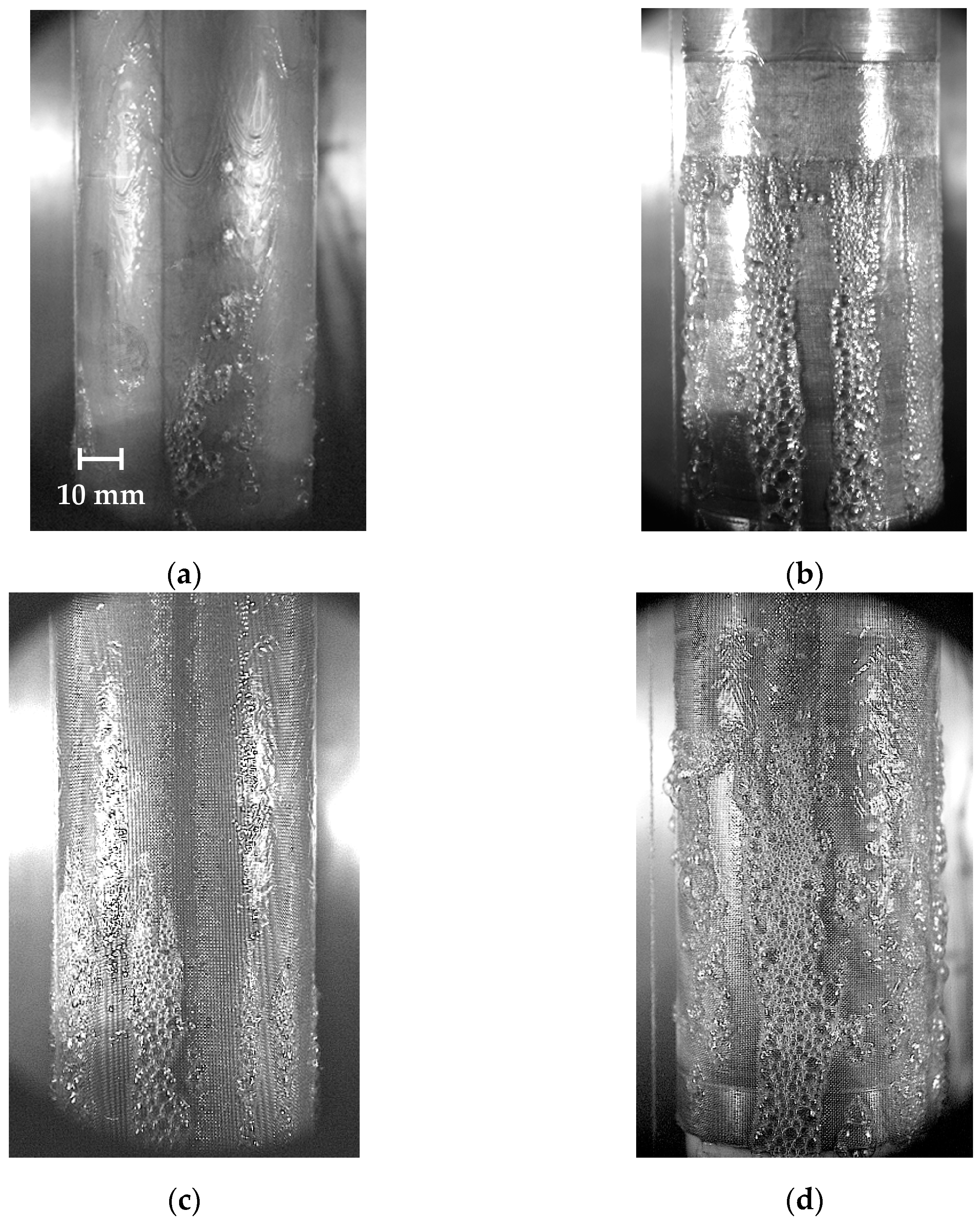
Figure 4a–d illustrates the boiling process of the R114/R21 mixture falling film on studied test sections at the initial stages of nucleate boiling. The test sections structured by deformational cutting, both uncovered (
Figure 4b) and having mesh covering (
Figure 4d), demonstrate a more effective nucleation process than sections without basic MDC-structuring (
Figure 4a,c), with nucleation sites activated from the beginning of heating area—so it becomes visible—to its end.
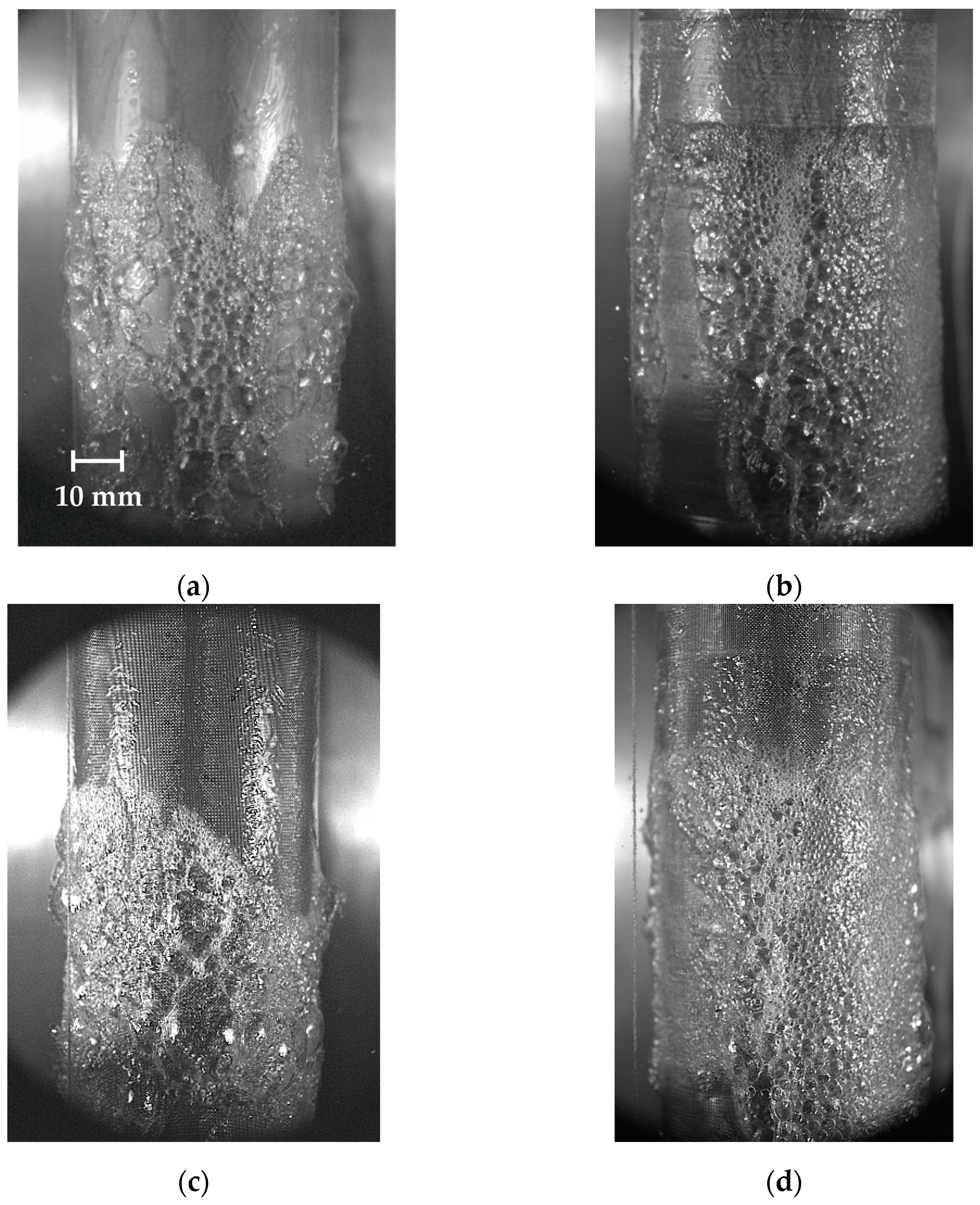
Figure 5a–d demonstrate the nucleate boiling of binary mixture falling film on studied sections at developed boiling regime—with the presence of very large bubbles (see for example
Figure 5c) characteristic of the mixtures and according to our observations does not occur in pure refrigerants. Again it can be noted that both test sections with substrate structured by deformational cutting (
Figure 5b,d) demonstrate a more effective nucleation process with nucleation sites evenly distributed over the entire heat-releasing surface. Next will be shown that the heat transfer data confirm the visual observation.
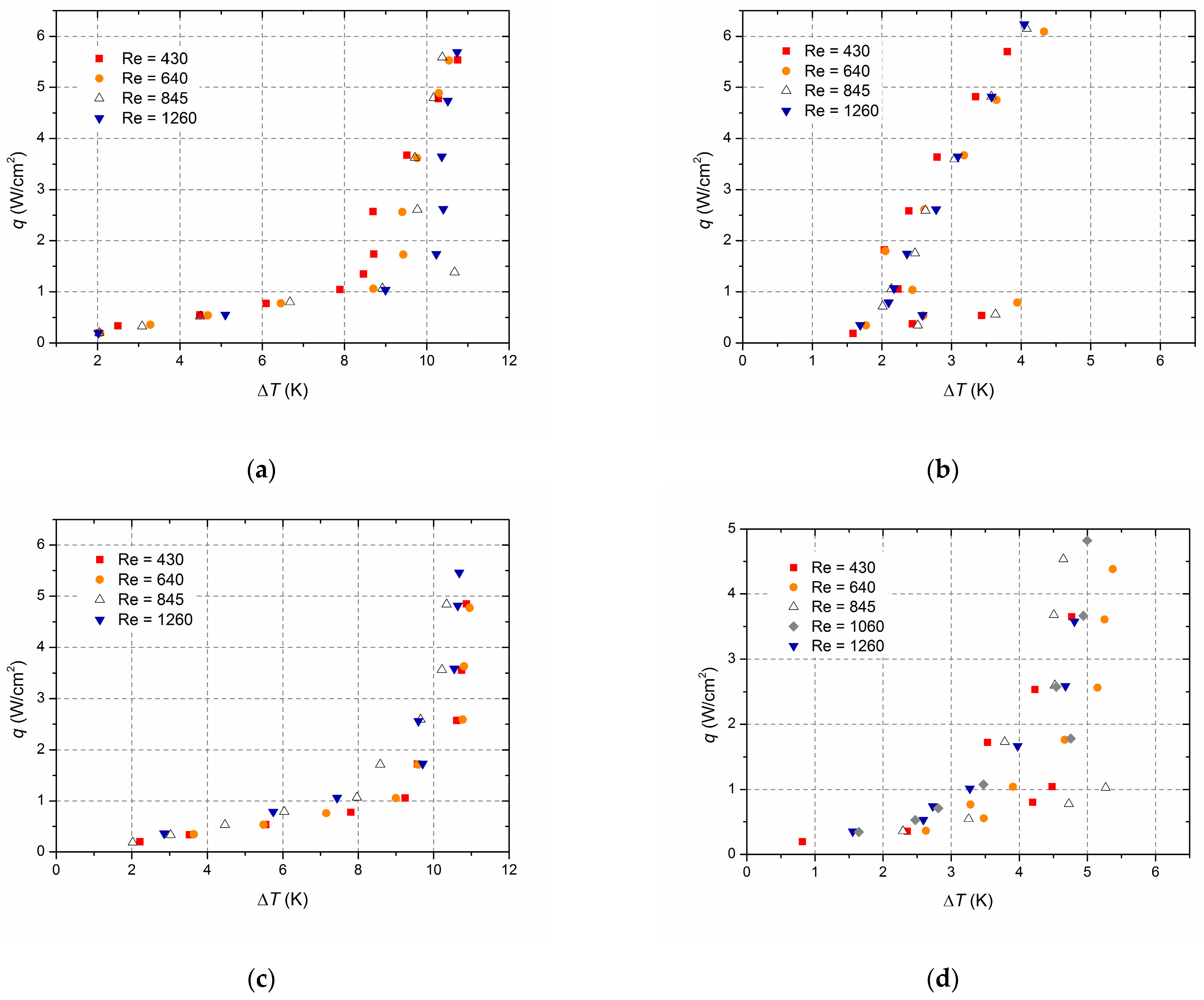
Boiling curves obtained for the investigated surfaces are shown in
Figure 6a–d.
Figure 6a shows the boiling curve for the smooth surface. In the film evaporation regime (
q ≤ 1 W/cm
2), the flow rate does not affect heat transfer. For all Reynolds numbers, ONB takes place at
q ≥ 1 W/cm
2 and incipience superheat Δ
T ≈ 8 K, respectively. Above Δ
T ≈ 8 K and up to the developed boiling regime (Δ
T ≈ 10.5 K), an insignificant effect of the flow rate on heat transfer is observed—the thinner the film, the higher heat transfer, as a rule. This could be due to the different contributions of evaporation to heat transfer, which takes place for different thicknesses of the falling film in the developing boiling regime. However, this effect is weakly expressed, and the presence of any kind of microtexture (
Figure 6b–d) immediately shuffles the cards.
Microstructured surface by the method of DC (
Figure 6b) demonstrates the greatest heat transfer efficiency, while the presence of the mesh covering does not affect (
Figure 6c), or even worsens (
Figure 6d), the heat transfer process. In the first case, we suppose, this is due to the fact that stainless steel (AISI 304) mesh used in the experimental series has a low thermal conductivity (15 W/mK), and the method of mesh attachment used is apparently not effective enough to create an ideal mesh-heated surface contact. In the case of combined surface, this also can be connected with the fact that we did not choose the mesh covering parameters well enough for our experimental conditions, which may cause the deterioration of vapor removal.
Thus, despite the fact that the presence of an applied steel mesh covering to some extent orders nucleate boiling (one can compare boiling patterns on mesh-covered surfaces in
Figure 4c,d and on the smooth one in
Figure 4a), taking into account the deterioration of heat transfer, at the next stage of the experiment, measures should take into account the existing shortcomings of the mesh coating used. It is planned to use highly thermally conductive copper mesh coatings and the process of sintering to ensure contact of the mesh covering with the heated surface; a more careful selection of mesh covering parameters also should be provided.
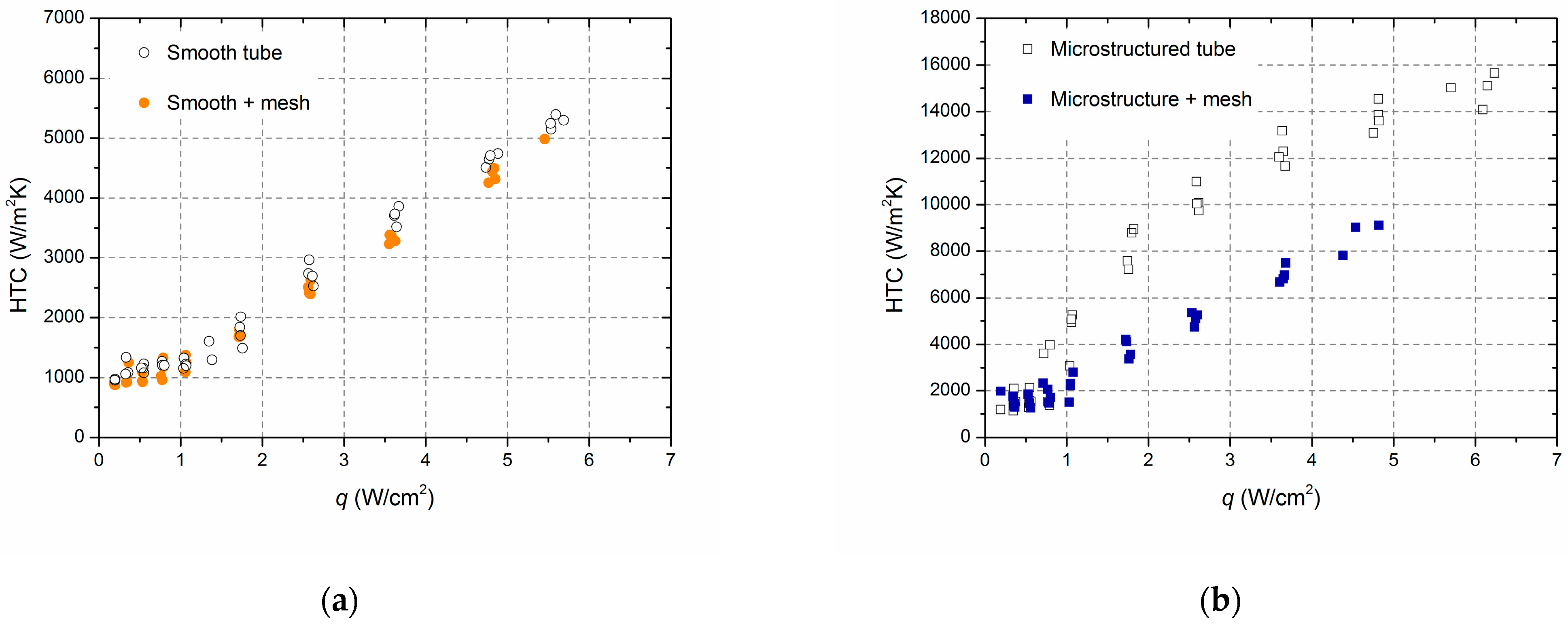
A comparison of experimental data on HTC and its enhancement on the studied surfaces for the range of Reynolds number 400 ÷ 1300 is presented in
Figure 7a,b. As noted above, the presence of mesh with the given characteristics does not enhance the boiling process when covering the smooth surface: data on HTC coincide with data for a smooth surface,
Figure 7a. The microstructured surface, created by deformational cutting (
Figure 7b), demonstrates the greatest heat transfer enhancement (up to four times as compared with the smooth one). In the case of mesh overlay of the microstructured surface (i.e. in the case of combined coating), even impairment (up to two times) in heat transfer as compared to high-performance MDC-surface is observed,
Figure 7b.
A brief discussion on the problem of the correct selection of the upper mesh covering parameters is given at the end of the section.
There are not many correlations for predicting pool boiling heat transfer coefficients for microstructured surfaces. We were able to find the calculation dependencies for predicting the pool boiling HTC for microfinned surfaces in [
29,
30]. Next, we tried to compare the obtained data for the MDC surface with these correlations, assuming that the process of developed nucleate boiling should be very similar for falling films and pool boiling. The main difference is brought by the evaporation of the film, however, in a developed boiling regime, its role decreases to a negligible value. We also neglected the presence of additional longitudinal knurling, present on the MDC-surface over the microfinning, since there are no calculation dependencies for such geometry in the literature (the correlation proposed in [
29] for the prediction of boiling on micropin surfaces also gives greatly overestimated values in case of our MDC-surface).
The calculation dependence of Aksyanov et al. [
29] has the form:
where
α,
α0 are the heat transfer coefficients of microstructured and smooth surfaces;
Kq is the dimensionless criterion, namely, the scale of the averaged velocity of liquid resulting from a vapor generation process:
;
l0 is the Laplace constant
;
ρ′ and
ρ″ are the liquid and vapor density;
ν′ is the fluid kinematic viscosity;
r is the latent heat of vaporization;
σ is the surface tension coefficient. Geometrical parameters are the following: the angle of fin inclination—
θ; fin height—
h; gap between the fins—Δ; average fin thickness—
δ.
The formula for
α0 expresses a standardized heat transfer coefficient:
where
Pcr and
Tcr are the critical pressure and critical temperature of the coolant, and
M is the molecular weight of the coolant. The calculation dependence proposed in [
29] by Formulas (6) and (7) makes it possible to predict heat transfer without requiring empirical parameters. However, it is worth noting that Formula (7) in our case gave overestimated values of
α0, so we used our own experimental data for smooth surface (
Figure 6a) as reference values.
The dependence proposed by Huang [
30] has the form of:
where
kl is the liquid thermal conductivity;
TS—saturation temperature and
Pfin is fin pitch.
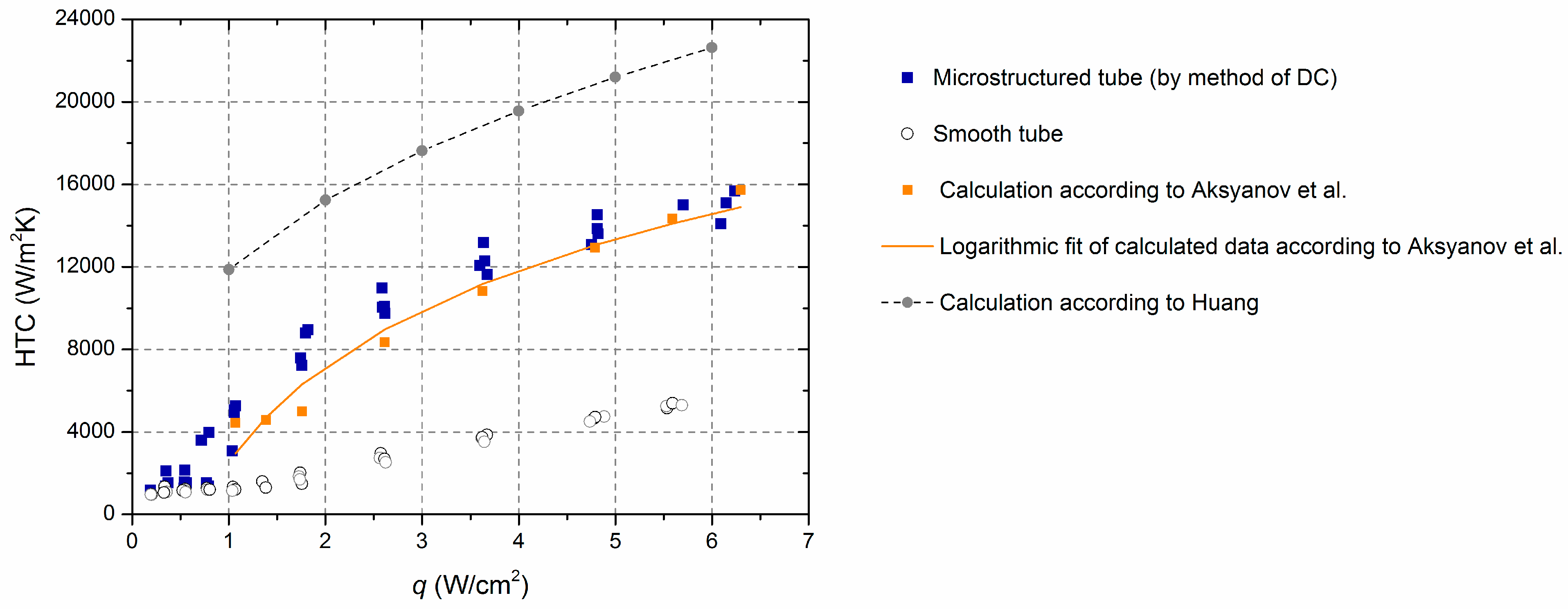
Comparison of received experimental data on HTC vs. heat flux for microstructured by MDC surface with the correlations for microfinned surfaces (6,8) shown in
Figure 8. For reference,
Figure 8 also shows the experimental data obtained for a smooth surface. As noted, the heat transfer enhancement on the microstructured tube is about 3–4 times more as compared to the smooth surface even at small heat fluxes, and ONB begins at heat flux values about 2 times less than those for the smooth surface. In fact, the maximal heat transfer enhancement up to 4 times takes place, namely, in the region of small heat fluxes (
q: 1 ÷ 2.6 W/cm
2) because in this case, we compare the quite developed boiling on the MDC-surface with a highly underdeveloped boiling regime on the smooth surface.
The dependence (6) for a microfinned structure quite well describes the obtained experimental data for the microstructured MDC-surface, even better than within a deviation of 30%, as stated by the authors of [
29]. Some excess of the experimental data over the predicted data (here the logarithmic fit of calculated points is implied) in the region of heat fluxes
q ≤ 4 W/cm
2 can be associated with the presence of additional knurling, which creates partly closed pores and intensifies heat transfer as compared to microfinned surfaces (according to our assumptions), so with the fact that we used the dependence (6) developed for a pool boiling to describe the falling films data: it is known that the contribution of falling film evaporation can give an additional increase in heat transfer as compared to pool boiling, especially at low and moderate heat fluxes, reaching 20–30%. The appearance of a step in the calculated HTC values by (6) in
Figure 8 in the region of low heat fluxes (1 ÷ 1.8 W/cm
2) is due to the presence of an underdeveloped boiling regime on the smooth surface with low HTCs, which are substituted into (6) giving low values of
α.
The dependence (8), on the contrary, does not work in our case, about two times exceeding the HTC data obtained, although it can be noted that both correlations have very similar character of the dependence of HTC on the heat flux.
In conclusion, it can be added that next exceeding the heat flux values provided in
Figure 8 leads to the flattening of HTC vs.
q dependence, associated with the appearance of washable dry spots, beginning from the lower part of the heated tube. Dry spots appear after reaching of CHF in places where the film is thinned, for example, such regions are visible in
Figure 5a like bare zones (but in fact, these regions are still covered with a microlayer of liquid film). The microstructured surfaces, similar to those used in this work, in addition to increasing the heat transfer coefficient and reducing the ONB, provide the capillary replenishment of nucleation centers with liquid, making it possible to delay the development of the crisis phenomena. According to our estimates, based on a study of heat transfer on similar MDC-surfaces earlier [
22], the minimal increase in CHF on the MDC-surface used in this work may be about 2 times as compared to the smooth surface, namely, to reach about 12 W/cm
2 for the upper values of the passed range of liquid flow rates.
Below, we briefly discuss the possible causes of reducing heat transfer when using the combined coverage.
As already mentioned we attribute the absence of heat transfer enhancement for the stainless steel (AISI 304) mesh-covered smooth copper surface primarily to the low thermal conductivity of the used mesh material (
λ ≈ 15 W/mK) and the imperfect contact of the mesh with the heated surface (allowing the existence of gaps ~10 microns at the points of contact (despite our attempts to tighten the mesh covering on the tube as closely as possible). Maybe the second reason is even more important because there are works in which it is shown that steel coverings can be effective means of heat transfer. For example, in [
31] it is shown that HTC provided by 3D-printed capillary-porous stainless steel coating (LPW 155,
λ ≈ 20 W/mK) can be higher than HTC of the brass one (AISI C836000,
λ ≈ 89 W/mK) with the same parameters of porous structure, at boiling of n-dodecane in horizontal liquid layers at reduced pressures. Thus, these issues require additional research.
Also, especially in the case of combined surfaces, we should not discount the possibility that guided by the choice of mesh parameters based on the empirical data of other authors [
5,
6,
8] as well as our own previous data for microstructured surfaces [
22], we may not choose the mesh coverage parameters well enough for our experimental conditions, which may cause the deterioration of vapor removal.
Studying the one-layer mesh coverings with an aperture size larger than the bubble departure diameter as well as the order of the departure diameter and smaller than the departure diameter, Tolubinskiy et al. [
32] showed that the maximum HTC is realized at an aperture of the order of the bubble departure diameter. Based on this, we can assess that it is also true for the upper layer of two-layer coverings (or combined coatings with mesh covering the basic microstructure, like in our case). Then, the basic microstructure—or fine mesh in the case of two-layer mesh covering—is responsible for the intensification of the nucleation process and the upper coverage at least should not prevent effective vapor removal.
To estimate the value of departure diameter for the R114/R21 refrigerant mixture use the Labuntsov formula [
33]:
where
d0 is the characteristic size of the microroughness of the heating surface.
Based on Mahmoud and Karayiannis [
34] calculation, who used the Hsu model [
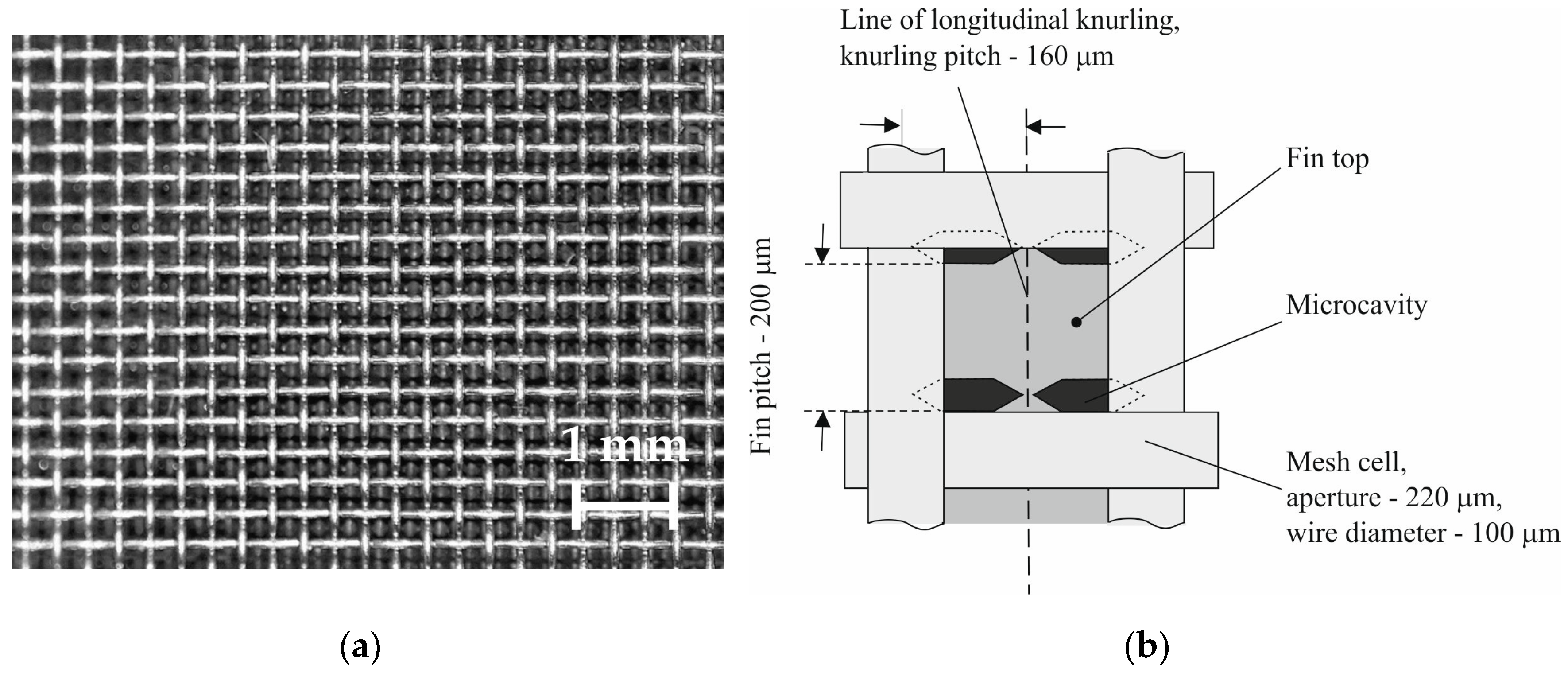
35] to predict the range of active cavity size for different liquids at atmospheric pressure and 5 K subcooling (5.5–126 μm, 0.7–108 μm, 0.4–79 μm—for water, HFE-7100 and FC-72, respectively), we can assume, without greatly deviating from the truth, that the range of active nucleation sites will be 1–100 μm for the R114/R21 refrigerant mixture (note, that this range includes the transverse dimensions of the gap between microfins,
Figure 1b). Substituting the minimum and maximum values of the range into Formula (9) as
d0, we have:
D ≈ 190 μm for the smallest cavities and
D ≈ 890 μm for the biggest ones.
Thus, according to the calculation, by using the mesh covering with an aperture of 220 μm perhaps we are preventing vapor removal. When choosing the mesh parameters, besides basing the choice on our own results on enhancing surfaces microstructure parameters [
22], we were guided by the parameters of enhancing covering from [
6] (consisting of three upper layers of mesh with aperture 254 µm and diameter 50 µm) as well as by the uniform covering parameters from [
8] (with aperture 100 µm and diameter 30 µm)—in both cases, the aperture of upper coverings was significantly less than the bubble departure diameter for water (
D ≈ 2 mm under standard conditions). As a result, our preference was given to mesh with an aperture of 220 µm (available with a wire diameter of 100 µm), slightly exceeding the pitch of the lower microfinning by MDC (200 µm). However, we did not take into account the fact that in previous work [
6,
8] boiling was carried out at high heat fluxes ~100 W/cm
2, an order of magnitude higher than maximum operating heat fluxes ~10 W/cm
2 in case of boiling refrigerant mixture R114/R21 films. At such high heat fluxes, cavities with the smallest dimensions can be activated. So, the different operating ranges of heat fluxes used in different works may be a possible cause of the discrepancy with respect to the choice of optimal aperture values of upper mesh coverings.
However, these are just some preliminary considerations, the issue of choosing covering geometrical parameters requires more precise analysis and calculations.


