

A Review on Heat Transfer Enhancement of Phase Change Materials Using Fin Tubes

Abstract
:1. Introduction
2. Heat Transfer Enhancement of Fin Structure in LHTES Device
2.1. Rectangular Fin
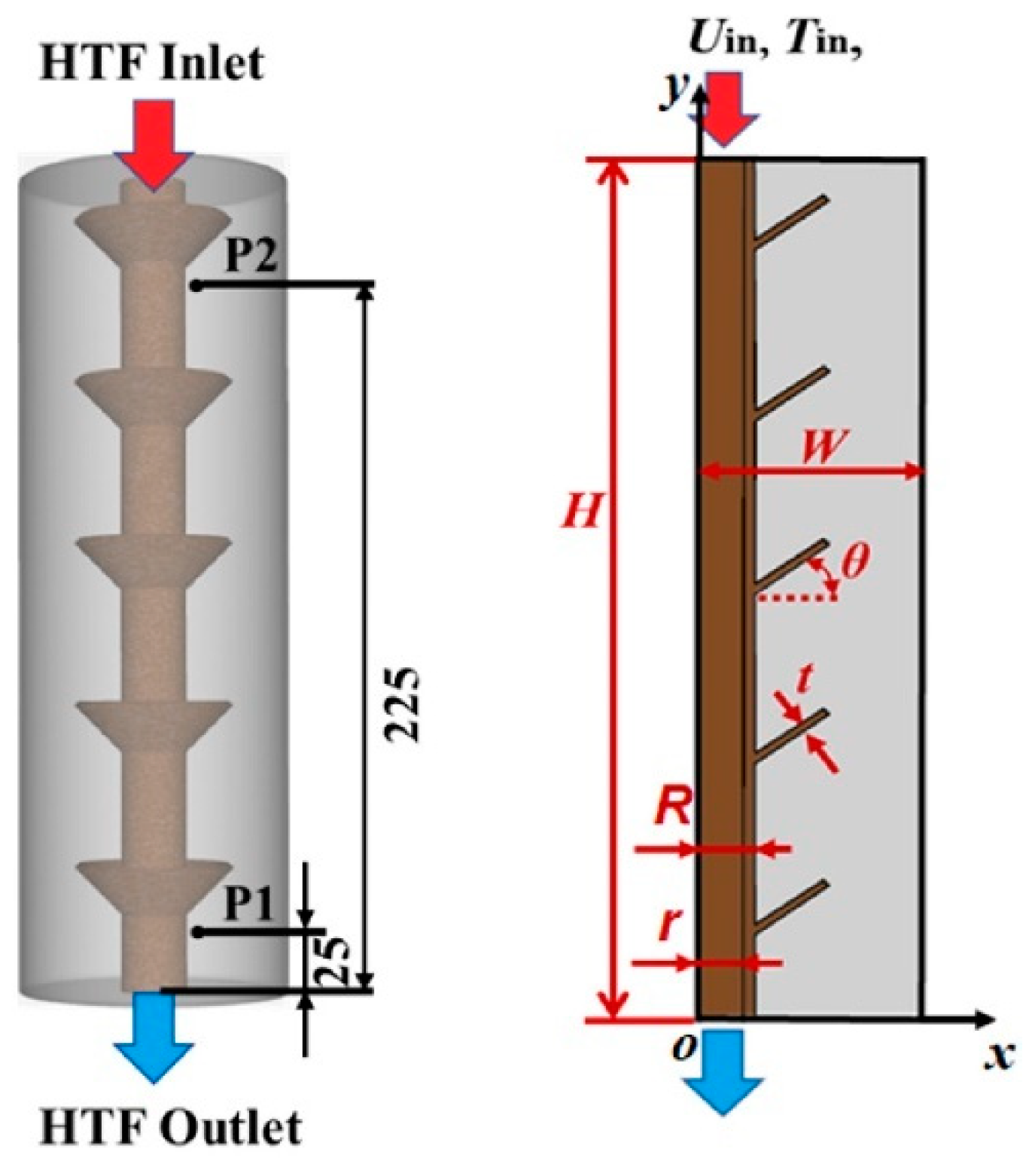
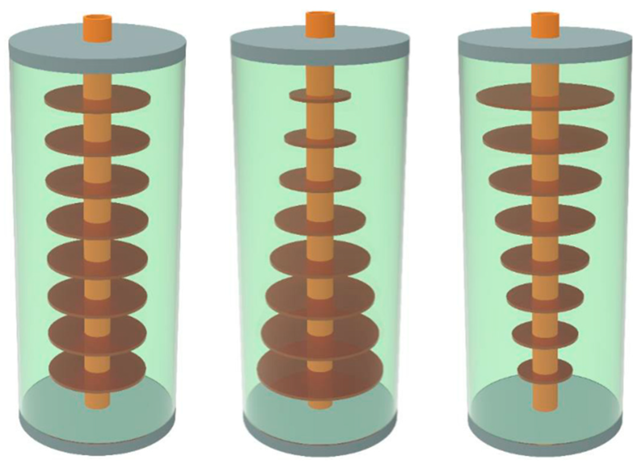
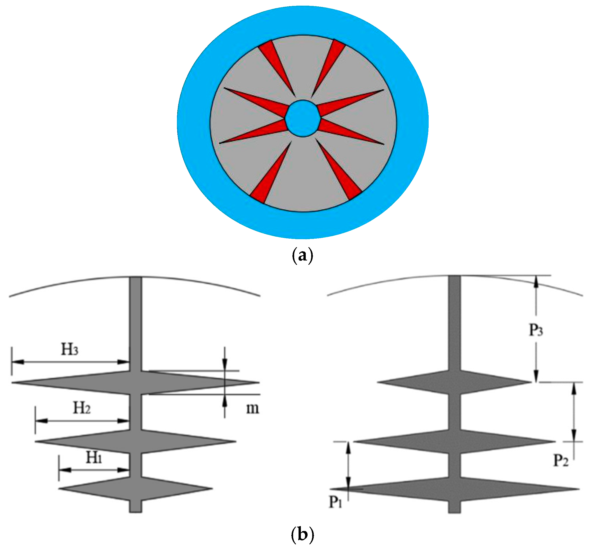
2.2. Annular Fin
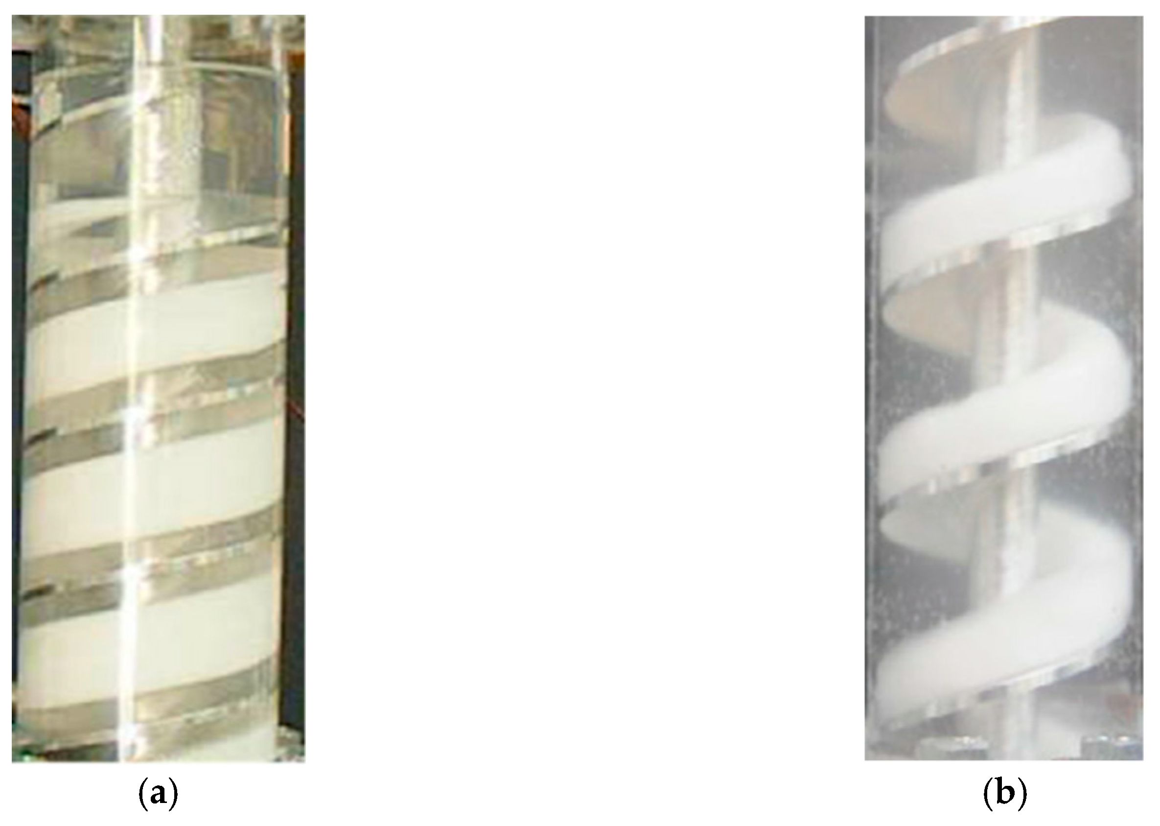
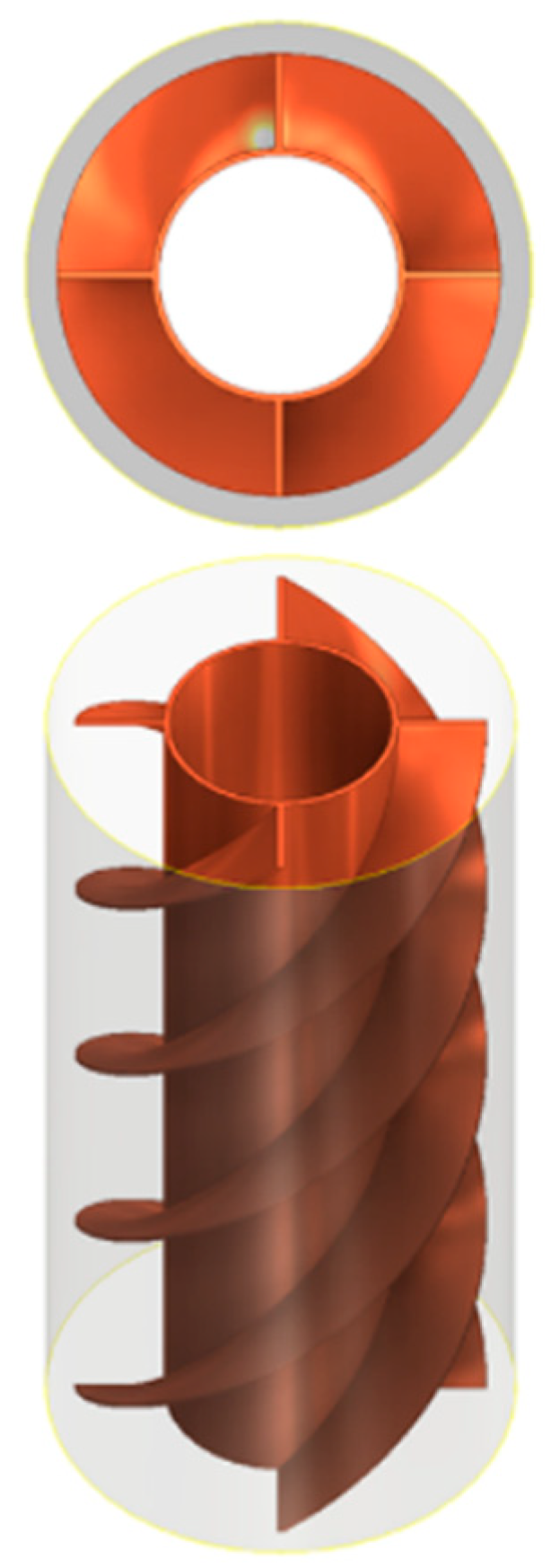
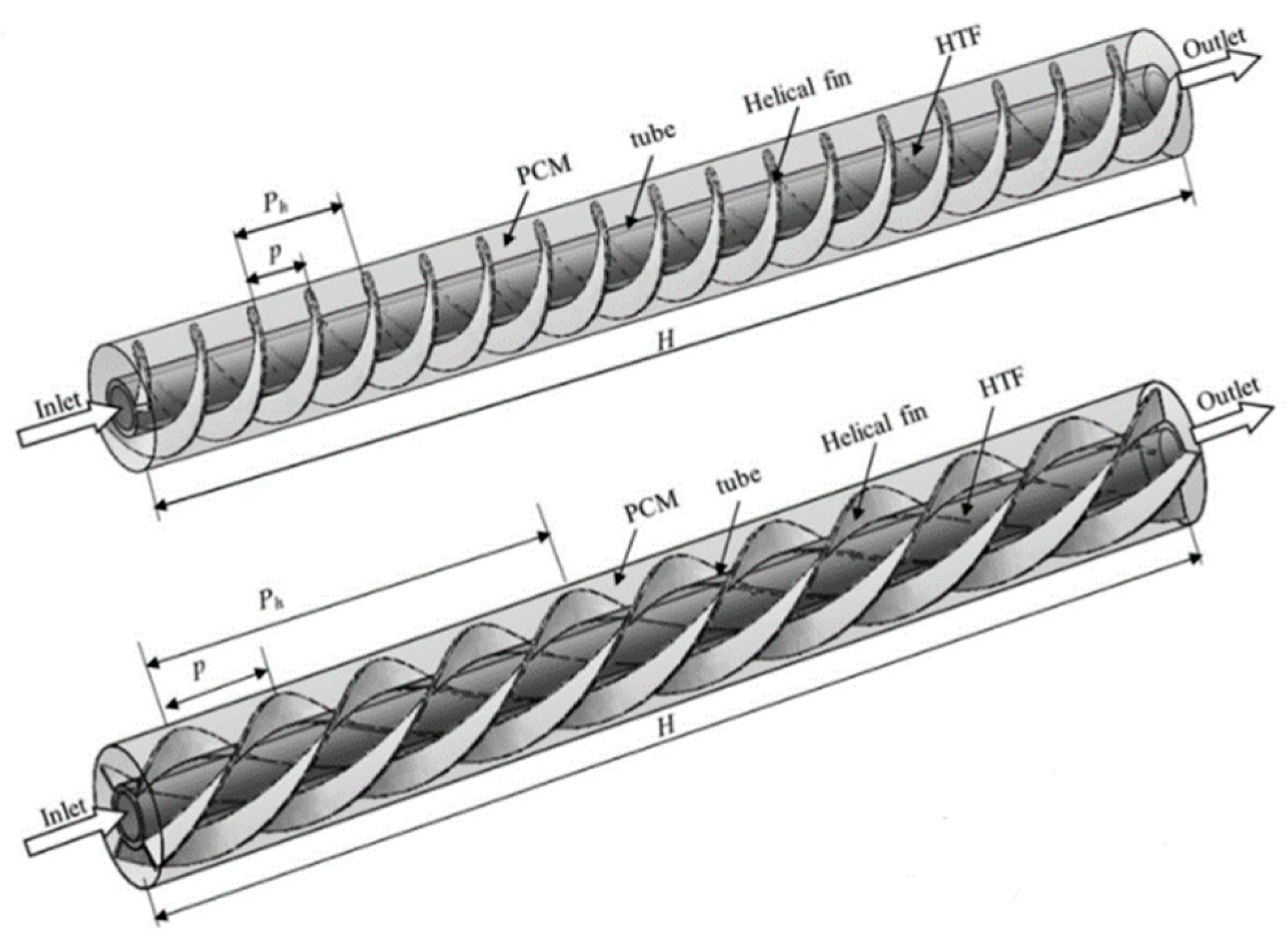
2.3. Spiral Fin
2.4. Plate Fin
2.5. Topology Optimized Fin
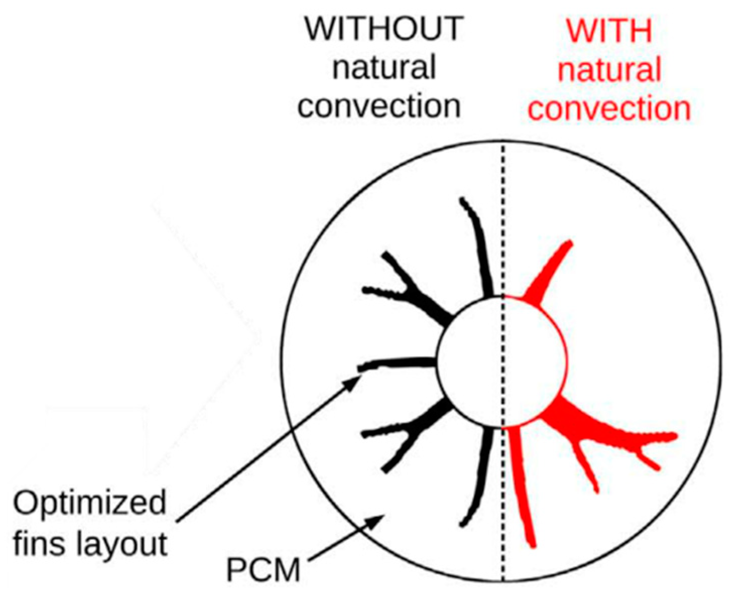
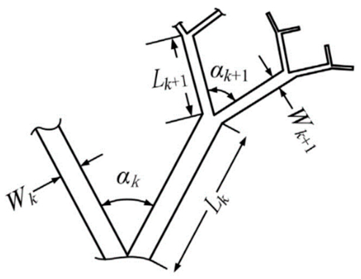
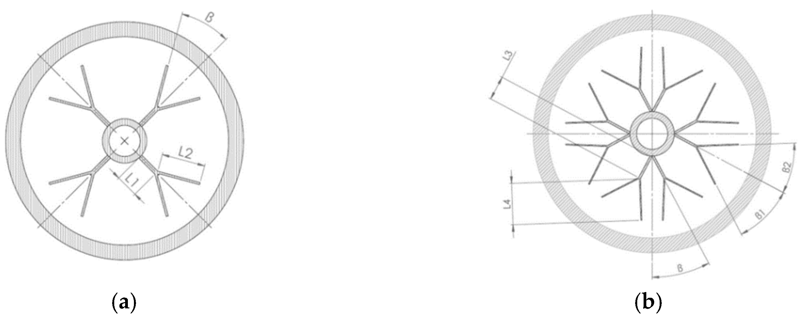
2.6. Dendritic Fin
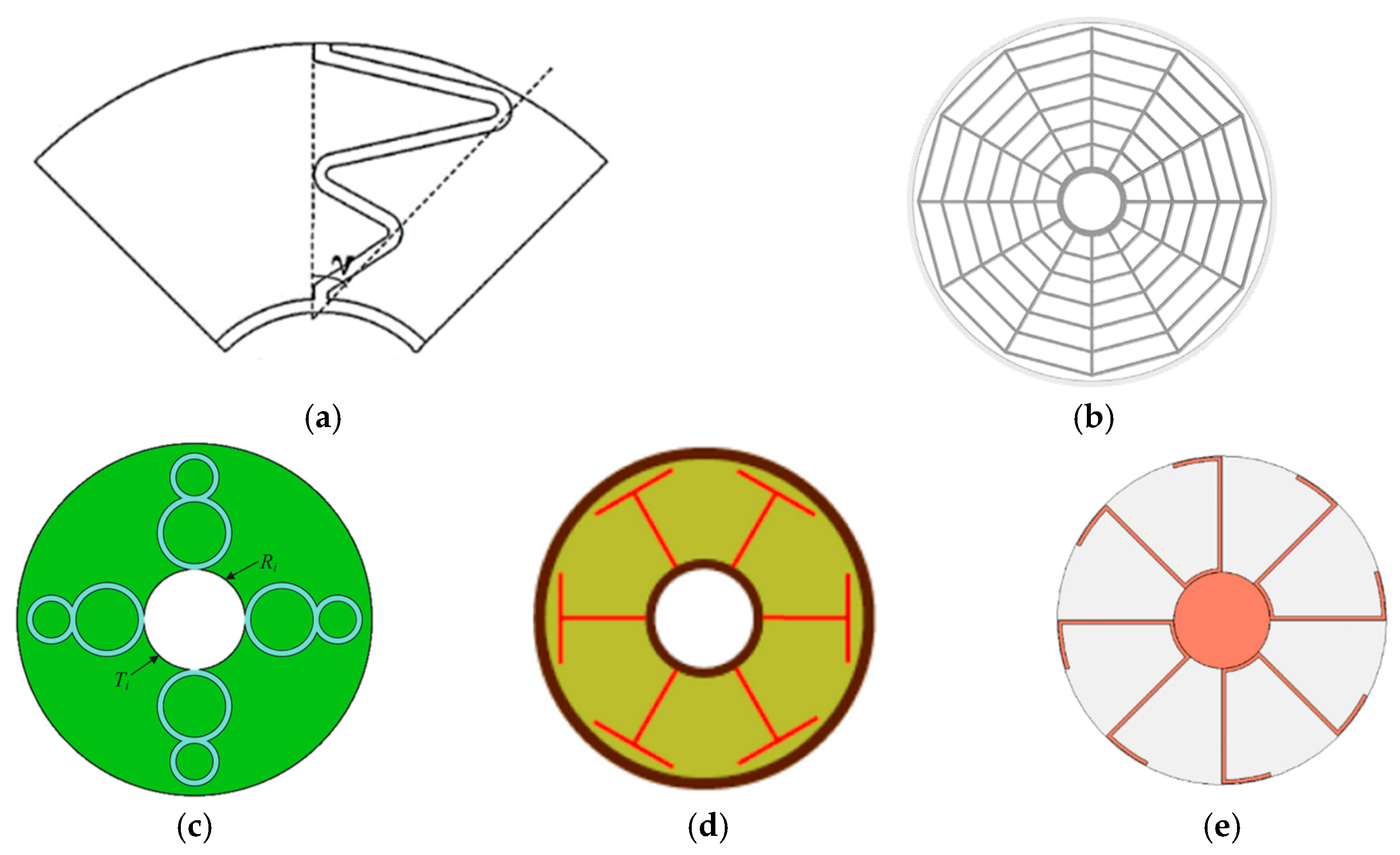
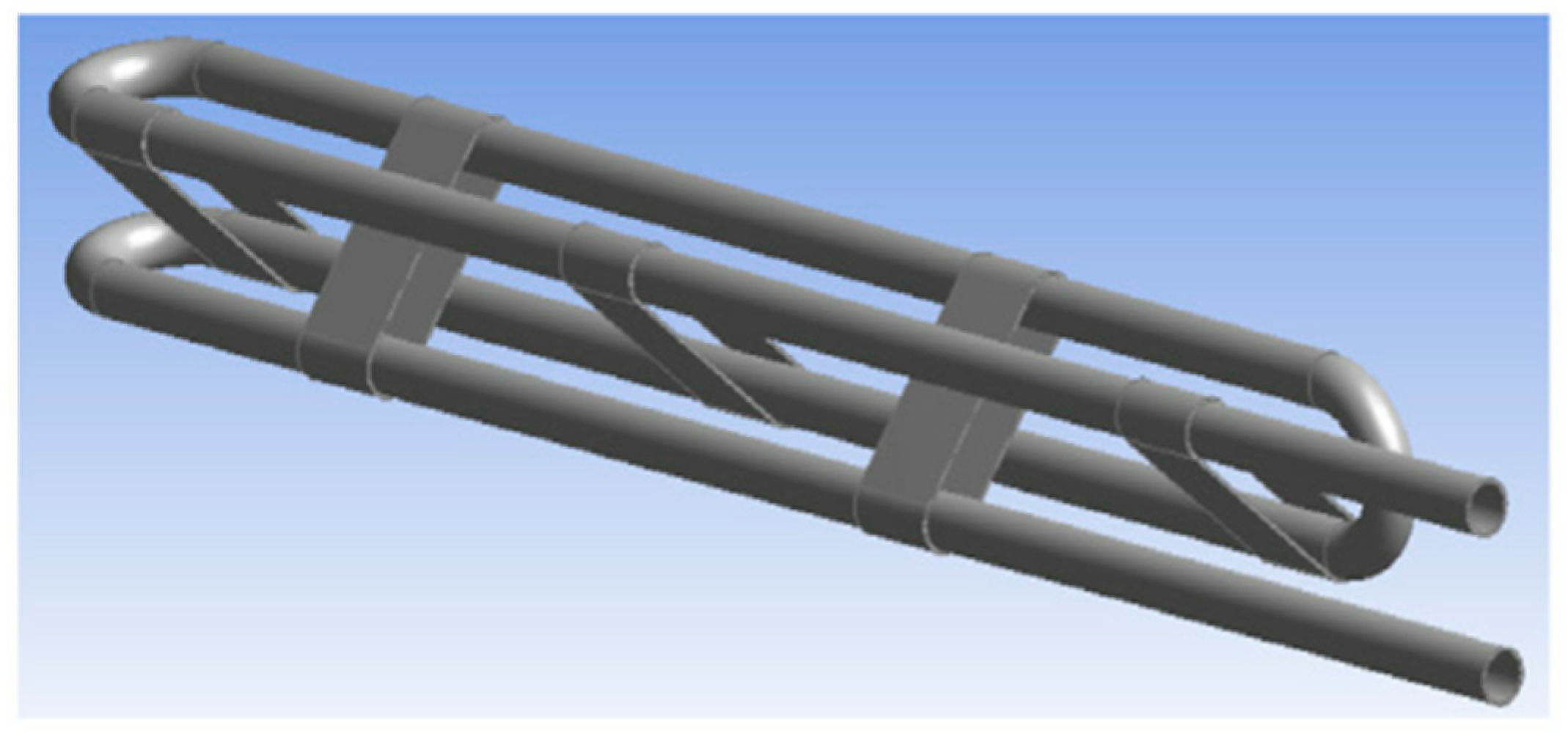
2.7. Other Fins
3. Comparison between Different Fin Structures
4. Conclusions and Perspective
Author Contributions
Funding
Data Availability Statement
Conflicts of Interest
References
- Sharma, A.; Tyagi, V.V.; Chen, C.R.; Buddhi, D. Review on Thermal Energy Storage with Phase Change Materials and Applications. Renew. Sustain. Energy Rev. 2009, 13, 318–345. [Google Scholar] [CrossRef]
- Li, Q.; Li, C.; Du, Z.; Jiang, F.; Ding, Y. A Review of Performance Investigation and Enhancement of Shell and Tube Thermal Energy Storage Device Containing Molten Salt Based Phase Change Materials for Medium and High Temperature Applications. Appl. Energy 2019, 255, 113806. [Google Scholar] [CrossRef]
- Tang, S.-Z.; Tian, H.-Q.; Zhou, J.-J.; Li, H. Evaluation and Optimization of Melting Performance in a Horizontal Thermal Energy Storage Unit with Non-Uniform Fins. J. Energy Storage 2021, 33, 102124. [Google Scholar] [CrossRef]
- Pu, L.; Zhang, S.; Xu, L.; Li, Y. Thermal Performance Optimization and Evaluation of a Radial Finned Shell-and-Tube Latent Heat Thermal Energy Storage Unit. Appl. Therm. Eng. 2020, 166, 114753. [Google Scholar] [CrossRef]
- Mehta, D.S.; Vaghela, B.; Rathod, M.K.; Banerjee, J. Thermal Performance Augmentation in Latent Heat Storage Unit Using Spiral Fin: An Experimental Analysis. J. Energy Storage 2020, 31, 101776. [Google Scholar] [CrossRef]
- Amagour, M.E.H.; Bennajah, M.; Rachek, A. Numerical Investigation and Experimental Validation of the Thermal Performance Enhancement of a Compact Finned-Tube Heat Exchanger for Efficient Latent Heat Thermal Energy Storage. J. Clean. Prod. 2021, 280, 124238. [Google Scholar] [CrossRef]
- Wu, S.; Huang, Y.; Zhang, C.; Chen, Y. Role of Tree-Shaped Fins in Charging Performance of a Latent Heat Storage Unit. Int. J. Energy Res. 2020, 44, 4800–4811. [Google Scholar] [CrossRef]
- Li, S.; Liu, Z.; Wang, X. A comprehensive review on positive cold energy storage technologies and applications in air conditioning with phase change materials. Appl. Energy 2019, 255, 113667. [Google Scholar] [CrossRef]
- Rostami, S.; Afrand, M.; Shahsavar, A.; Sheikholeslami, M.; Kalbasi, R.; Aghakhani, S.; Shadloo, M.S.; Oztop, H.F. A review of melting and freezing process of PCM/nano-PCM and their application in energy storage. Energy 2020, 211, 118698. [Google Scholar] [CrossRef]
- Yang, L.; Jin, X.; Zhang, Y.; Du, K. Recent development on heat transfer and various applications of phase-change materials. J. Clean. Prod. 2021, 287, 124432. [Google Scholar] [CrossRef]
- Agyenim, F.; Hewitt, N.; Eames, P.; Smyth, M. A Review of Materials, Heat Transfer and Phase Change Problem Formulation for Latent Heat Thermal Energy Storage Systems (LHTESS). Renew. Sustain. Energy Rev. 2010, 14, 615–628. [Google Scholar] [CrossRef]
- Nie, C.; Deng, S.; Liu, J. Effects of Fins Arrangement and Parameters on the Consecutive Melting and Solidification of PCM in a Latent Heat Storage Unit. J. Energy Storage 2020, 29, 101319. [Google Scholar] [CrossRef]
- Mahood, H.B.; Mahdi, M.S.; Monjezi, A.A.; Khadom, A.A.; Campbell, A.N. Numerical Investigation on the Effect of Fin Design on the Melting of Phase Change Material in a Horizontal Shell and Tube Thermal Energy Storage. J. Energy Storage 2020, 29, 101331. [Google Scholar] [CrossRef]
- Li, H.; Hu, C.; He, Y.; Tang, D.; Wang, K. Influence of Fin Parameters on the Melting Behavior in a Horizontal Shell-and-Tube Latent Heat Storage Unit with Longitudinal Fins. J. Energy Storage 2021, 34, 102230. [Google Scholar] [CrossRef]
- Soltani, H.; Soltani, M.; Karimi, H.; Nathwani, J. Heat Transfer Enhancement in Latent Heat Thermal Energy Storage Unit Using a Combination of Fins and Rotational Mechanisms. Int. J. Heat Mass Transf. 2021, 179, 121667. [Google Scholar] [CrossRef]
- Kumar, R.; Verma, P. An Experimental and Numerical Study on Effect of Longitudinal Finned Tube Eccentric Configuration on Melting Behaviour of Lauric Acid in a Horizontal Tube-in-Shell Storage Unit. J. Energy Storage 2020, 30, 101396. [Google Scholar] [CrossRef]
- Kazemi, M.; Hosseini, M.J.; Ranjbar, A.A.; Bahrampoury, R. Improvement of Longitudinal Fins Configuration in Latent Heat Storage Systems. Renew. Energy 2018, 116, 447–457. [Google Scholar] [CrossRef]
- Khan, L.A.; Khan, M.M. Role of Orientation of Fins in Performance Enhancement of a Latent Thermal Energy Storage Unit. Appl. Therm. Eng. 2020, 175, 115408. [Google Scholar] [CrossRef]
- Deng, S.; Nie, C.; Wei, G.; Ye, W.-B. Improving the Melting Performance of a Horizontal Shell-Tube Latent-Heat Thermal Energy Storage Unit Using Local Enhanced Finned Tube. Energy Build. 2019, 183, 161–173. [Google Scholar] [CrossRef]
- Deng, S.; Nie, C.; Jiang, H.; Ye, W.-B. Evaluation and Optimization of Thermal Performance for a Finned Double Tube Latent Heat Thermal Energy Storage. Int. J. Heat Mass Transf. 2019, 130, 532–544. [Google Scholar] [CrossRef]
- Yu, C.; Zhang, X.; Chen, X.; Zhang, C.; Chen, Y. Melting Performance Enhancement of a Latent Heat Storage Unit Using Gradient Fins. Int. J. Heat Mass Transf. 2020, 150, 119330. [Google Scholar] [CrossRef]
- Mahdi, M.S.; Hasan, A.F.; Mahood, H.B.; Campbell, A.N.; Khadom, A.A.; Karim, A.M.A.; Sharif, A.O. Numerical Study and Experimental Validation of the Effects of Orientation and Configuration on Melting in a Latent Heat Thermal Storage Unit. J. Energy Storage 2019, 23, 456–468. [Google Scholar] [CrossRef]
- Khan, L.A.; Khan, M.M.; Ahmed, H.F.; Irfan, M.; Brabazon, D.; Ahad, I.U. Dominant Roles of Eccentricity, Fin Design, and Nanoparticles in Performance Enhancement of Latent Thermal Energy Storage Unit. J. Energy Storage 2021, 43, 103181. [Google Scholar] [CrossRef]
- Khan, Z.; Khan, Z.A. An Experimental Investigation of Discharge/Solidification Cycle of Paraffin in Novel Shell and Tube with Longitudinal Fins Based Latent Heat Storage System. Energy Convers. Manag. 2017, 154, 157–167. [Google Scholar] [CrossRef] [Green Version]
- Nóbrega, C.R.E.S.; Ismail, K.A.R.; Lino, F.A.M. Solidification around Axial Finned Tube Submersed in PCM: Modeling and Experiments. J. Energy Storage 2020, 29, 101438. [Google Scholar] [CrossRef]
- Pan, C.; Vermaak, N.; Romero, C.; Neti, S.; Hoenig, S.; Chen, C.-H. Efficient Optimization of a Longitudinal Finned Heat Pipe Structure for a Latent Thermal Energy Storage System. Energy Convers. Manag. 2017, 153, 93–105. [Google Scholar] [CrossRef]
- Dai, R.; Mostaghimi, J.; Li, N.; Deng, T.; Wang, Q.; Zeng, M. Charging Time and Energy Storage Rate Analysis of Fin Effect inside the Horizontal Tube for Thermal Energy Storage. J. Clean. Prod. 2020, 273, 123030. [Google Scholar] [CrossRef]
- Qaiser, R.; Khan, M.M.; Khan, L.A.; Irfan, M. Melting Performance Enhancement of PCM Based Thermal Energy Storage System Using Multiple Tubes and Modified Shell Designs. J. Energy Storage 2021, 33, 102161. [Google Scholar] [CrossRef]
- Kirincic, M.; Trp, A.; Lenic, K. Numerical Evaluation of the Latent Heat Thermal Energy Storage Performance Enhancement by Installing Longitudinal Fins. J. Energy Storage 2021, 42, 103085. [Google Scholar] [CrossRef]
- Kirincic, M.; Trp, A.; Lenic, K. Influence of Natural Convection during Melting and Solidification of Paraffin in a Longitudinally Finned Shell-and-Tube Latent Thermal Energy Storage on the Applicability of Developed Numerical Models. Renew. Energy 2021, 179, 1329–1344. [Google Scholar] [CrossRef]
- Eslamnezhad, H.; Rahimi, A.B. Enhance Heat Transfer for Phase-Change Materials in Triplex Tube Heat Exchanger with Selected Arrangements of Fins. Appl. Therm. Eng. 2017, 113, 813–821. [Google Scholar] [CrossRef]
- Mahdi, J.M.; Nsofor, E.C. Melting Enhancement in Triplex-Tube Latent Thermal Energy Storage System Using Nanoparticles-Fins Combination. Int. J. Heat Mass Transf. 2017, 109, 417–427. [Google Scholar] [CrossRef]
- Cao, X.; Yuan, Y.; Xiang, B.; Sun, L.; Xingxing, Z. Numerical Investigation on Optimal Number of Longitudinal Fins in Horizontal Annular Phase Change Unit at Different Wall Temperatures. Energy Build. 2018, 158, 384–392. [Google Scholar] [CrossRef]
- Zarei, M.J.; Bazai, H.; Sharifpur, M.; Mahian, O.; Shabani, B. The Effects of Fin Parameters on the Solidification of PCMs in a Fin-Enhanced Thermal Energy Storage System. Energies 2020, 13, 198. [Google Scholar] [CrossRef] [Green Version]
- Joybari, M.M.; Haghighat, F.; Seddegh, S.; Al-Abidi, A.A. Heat Transfer Enhancement of Phase Change Materials by Fins under Simultaneous Charging and Discharging. Energy Convers. Manag. 2017, 152, 136–156. [Google Scholar] [CrossRef]
- Zhai, X.Q.; Cheng, X.W.; Wang, C.; Wang, R.Z. Experimental Investigation and Performance Analysis of a Fin Tube Phase Change Cold Storage Unit for High Temperature Cooling Application. Energy Build. 2015, 89, 9–17. [Google Scholar] [CrossRef]
- Hosseinzadeh, K.; Mogharrebi, A.R.; Asadi, A.; Paikar, M.; Ganji, D.D. Effect of Fin and Hybrid Nano-Particles on Solid Process in Hexagonal Triplex Latent Heat Thermal Energy Storage System. J. Mol. Liq. 2020, 300, 112347. [Google Scholar] [CrossRef]
- Hosseinzadeh, K.; Moghaddam, M.A.E.; Asadi, A.; Mogharrebi, A.R.; Ganji, D.D. Effect of Internal Fins along with Hybrid Nano-Particles on Solid Process in Star Shape Triplex Latent Heat Thermal Energy Storage System by Numerical Simulation. Renew. Energy 2020, 154, 497–507. [Google Scholar] [CrossRef]
- Hosseinzadeh, K.; Montazer, E.; Shafii, M.B.; Ganji, A.R.D. Solidification Enhancement in Triplex Thermal Energy Storage System via Triplets Fins Configuration and Hybrid Nanoparticles. J. Energy Storage 2021, 34, 102177. [Google Scholar] [CrossRef]
- Kok, B. Examining Effects of Special Heat Transfer Fins Designed for the Melting Process of PCM and Nano-PCM. Appl. Therm. Eng. 2020, 170, 114989. [Google Scholar] [CrossRef]
- Gürtürk, M.; Kok, B. A New Approach in the Design of Heat Transfer Fin for Melting and Solidification of PCM. Int. J. Heat Mass Transf. 2020, 153, 119671. [Google Scholar] [CrossRef]
- Ding, P.; Liu, Z. Numerical Investigation of Natural Convection Enhancement in Latent Heat Energy Storage Units with Punched-Fin and Slit-Fin. Int. J. Therm. Sci. 2021, 163, 106834. [Google Scholar] [CrossRef]
- Tokas, S.; Krishnayatra, G.; Zunaid, M. Numerical Investigation of Thermal Performance of Extended Surfaces for a Novel Heat Exchanger. Heat Transf. 2021, 50, 329–351. [Google Scholar] [CrossRef]
- Mahdi, J.M.; Najim, F.T.; Aljubury, I.M.A.; Mohammed, H.I.; Khedher, N.B.; Alshammari, N.K.; Cairns, A.; Talebizadehsardari, P. Intensifying the Thermal Response of PCM via Fin-Assisted Foam Strips in the Shell-and-Tube Heat Storage System. J. Energy Storage 2022, 45, 103733. [Google Scholar] [CrossRef]
- Malik, F.K.; Khan, M.M.; Ahmed, H.F.; Irfan, M.; Ahad, I.U. Performance characteristics of PCM based thermal energy storage system for fluctuating waste heat sources. Case Stud. Therm. Eng. 2022, 34, 102012. [Google Scholar] [CrossRef]
- Yang, X.; Lu, Z.; Bai, Q.; Zhang, Q.; Jin, L.; Yan, J. Thermal Performance of a Shell-and-Tube Latent Heat Thermal Energy Storage Unit: Role of Annular Fins. Appl. Energy 2017, 202, 558–570. [Google Scholar] [CrossRef]
- Cheng, H.; Luo, T.; Yu, J.; Yang, X.; Liu, Y.; Gu, Z.; Jin, L. Experimental Study of a Shell-and-Tube Phase Change Heat Exchanger Unit with/without Circular Fins. Energy Procedia 2018, 152, 990–996. [Google Scholar] [CrossRef]
- Shahsavar, A.; Goodarzi, A.; Mohammed, H.I.; Shirneshan, A.; Talebizadehsardari, P. Thermal Performance Evaluation of Non-Uniform Fin Array in a Finned Double-Pipe Latent Heat Storage System. Energy 2020, 193, 116800. [Google Scholar] [CrossRef]
- Bhagwat, V.V.; Roy, S.; Das, B.; Shah, N.; Chowdhury, A. Performance of Finned Heat Pipe Assisted Parabolic Trough Solar Collector System under the Climatic Condition of North East India. Sustain. Energy Technol. Assess. 2021, 45, 101171. [Google Scholar] [CrossRef]
- Ismail, K.A.R.; Alves, C.L.F.; Modesto, M.S. Numerical and Experimental Study on the Solidification of PCM around a Vertical Axially Finned Isothermal Cylinder. Appl. Therm. Eng. 2001, 25, 53–77. [Google Scholar] [CrossRef]
- dos Santos, F.S.; Ismail, K.A.R.; Lino, F.A.M.; Arabkoohsar, A.; Lago, T.G.S. Parametric Investigation of the Enhancing Effects of Finned Tubes on the Solidification of PCM. Int. J. Heat Mass Transf. 2020, 152, 119485. [Google Scholar] [CrossRef]
- Guo, J.; Liu, Z.; Yang, B.; Yang, X.; Yan, J. Melting Assessment on the Angled Fin Design for a Novel Latent Heat Thermal Energy Storage Tube. Renew. Energy 2022, 183, 406–422. [Google Scholar] [CrossRef]
- Parsazadeh, M.; Duan, X. Numerical Study on the Effects of Fins and Nanoparticles in a Shell and Tube Phase Change Thermal Energy Storage Unit. Appl. Energy 2018, 216, 142–156. [Google Scholar] [CrossRef]
- Mahmoud, M.Z.; Mohammed, H.I.; Mahdi, J.M.; Bokov, D.O.; Ben Khedher, N.; Alshammari, N.K.; Talebizadehsardari, P.; Yaici, W. Melting Enhancement in a Triple-Tube Latent Heat Storage System with Sloped Fins. Nanomaterials 2021, 11, 3153. [Google Scholar] [CrossRef] [PubMed]
- Karami, R.; Kamkari, B. Experimental Investigation of the Effect of Perforated Fins on Thermal Performance Enhancement of Vertical Shell and Tube Latent Heat Energy Storage Systems. Energy Convers. Manag. 2020, 210, 112679. [Google Scholar] [CrossRef]
- Li, H.; Hu, C.; He, Y.; Tang, D.; Wang, K.; Huang, W. Effect of Perforated Fins on the Heat-Transfer Performance of Vertical Shell-and-Tube Latent Heat Energy Storage Unit. J. Energy Storage 2021, 39, 102647. [Google Scholar] [CrossRef]
- Ghalambaz, M.; Mehryan, S.A.M.; Mozaffari, M.; Younis, O.; Ghosh, A. The Effect of Variable-Length Fins and Different High Thermal Conductivity Nanoparticles in the Performance of the Energy Storage Unit Containing Bio-Based Phase Change Substance. Sustainability 2021, 13, 2884. [Google Scholar] [CrossRef]
- Ghalambaz, M.; Mehryan, S.A.M.; Mahdavi, M.; Younis, O.; Alim, M.A. Evaluation of the Melting Performance in a Conical Latent Heat Thermal Unit Having Variable Length Fins. Sustainability 2021, 13, 2667. [Google Scholar] [CrossRef]
- Tiari, S.; Hockins, A.; Mahdavi, M. Numerical Study of a Latent Heat Thermal Energy Storage System Enhanced by Varying Fin Configurations. Case Stud. Therm. Eng. 2021, 25, 100999. [Google Scholar] [CrossRef]
- Kalapala, L.; Devanuri, J.K. Effect of Orientation on Thermal Performance of a Latent Heat Storage System Equipped with Annular Fins—An Experimental and Numerical Investigation. Appl. Therm. Eng. 2021, 183, 116244. [Google Scholar] [CrossRef]
- Rozenfeld, A.; Kozak, Y.; Rozenfeld, T.; Ziskind, G. Experimental Demonstration, Modeling and Analysis of a Novel Latent-Heat Thermal Energy Storage Unit with a Helical Fin. Int. J. Heat Mass Transf. 2017, 110, 692–709. [Google Scholar] [CrossRef]
- Mehta, D.S.; Vaghela, B.; Rathod, M.K.; Banerjee, J. Heat Transfer Enhancement Using Spiral Fins in Different Orientations of Latent Heat Storage Unit. Int. J. Therm. Sci. 2021, 169, 107060. [Google Scholar] [CrossRef]
- Duan, J.; Xiong, Y.; Yang, D. Study on the Effect of Multiple Spiral Fins for Improved Phase Change Process. Appl. Therm. Eng. 2020, 169, 114966. [Google Scholar] [CrossRef]
- Ghalambaz, M.; Mahdi, J.M.; Shafaghat, A.; Eisapour, A.H.; Younis, O.; Talebizadeh Sardari, P.; Yaici, W. Effect of Twisted Fin Array in a Triple-Tube Latent Heat Storage System during the Charging Mode. Sustainability 2021, 13, 2685. [Google Scholar] [CrossRef]
- Ghalambaz, M.; Mohammed, H.I.; Mahdi, J.M.; Eisapour, A.H.; Younis, O.; Ghosh, A.; Talebizadehsardari, P.; Yaici, W. Intensifying the Charging Response of a Phase-Change Material with Twisted Fin Arrays in a Shell-And-Tube Storage System. Energies 2021, 14, 1619. [Google Scholar] [CrossRef]
- Sun, X.; Mahdi, J.M.; Mohammed, H.I.; Majdi, H.S.; Zixiong, W.; Talebizadehsardari, P. Solidification Enhancement in a Triple-Tube Latent Heat Energy Storage System Using Twisted Fins. Energies 2021, 14, 7179. [Google Scholar] [CrossRef]
- Pakalka, S.; Valančius, K.; Streckienė, G. Experimental Comparison of the Operation of PCM-Based Copper Heat Exchangers with Different Configurations. Appl. Therm. Eng. 2020, 172, 115138. [Google Scholar] [CrossRef]
- Amagour, M.E.H.; Rachek, A.; Bennajah, M.; Ebn Touhami, M. Experimental Investigation and Comparative Performance Analysis of a Compact Finned-Tube Heat Exchanger Uniformly Filled with a Phase Change Material for Thermal Energy Storage. Energy Convers. Manag. 2018, 165, 137–151. [Google Scholar] [CrossRef]
- Mazhar, A.R.; Shukla, A.; Liu, S. Numerical Analysis of Rectangular Fins in a PCM for Low-Grade Heat Harnessing. Int. J. Therm. Sci. 2020, 152, 106306. [Google Scholar] [CrossRef]
- Deaton, J.D.; Grandhi, R.V. A Survey of Structural and Multidisciplinary Continuum Topology Optimization: Post 2000. Struct Multidisc Optim 2014, 49, 1–38. [Google Scholar] [CrossRef]
- Pizzolato, A.; Sharma, A.; Maute, K.; Sciacovelli, A.; Verda, V. Topology Optimization for Heat Transfer Enhancement in Latent Heat Thermal Energy Storage. Int. J. Heat Mass Transf. 2017, 113, 875–888. [Google Scholar] [CrossRef]
- Pizzolato, A.; Sharma, A.; Maute, K.; Sciacovelli, A.; Verda, V. Design of Effective Fins for Fast PCM Melting and Solidification in Shell-and-Tube Latent Heat Thermal Energy Storage through Topology Optimization. Appl. Energy 2017, 208, 210–227. [Google Scholar] [CrossRef]
- Pizzolato, A.; Sharma, A.; Ge, R.; Maute, K.; Verda, V.; Sciacovelli, A. Maximization of Performance in Multi-Tube Latent Heat Storage—Optimization of Fins Topology, Effect of Materials Selection and Flow Arrangements. Energy 2020, 203, 114797. [Google Scholar] [CrossRef]
- Ge, R.; Humbert, G.; Martinez, R.; Attallah, M.M.; Sciacovelli, A. Additive Manufacturing of a Topology-Optimised Multi-Tube Energy Storage Device: Experimental Tests and Numerical Analysis. Appl. Therm. Eng. 2020, 180, 115878. [Google Scholar] [CrossRef]
- You, Y.; Zhao, Y.; Zhao, C.; Liu, H. The topology optimization of the fin structure in latent heat storage. Chin. Sci. Bull. 2019, 64, 1191–1199. [Google Scholar] [CrossRef] [Green Version]
- Tian, Y.; Liu, X.; Xu, Q.; Luo, Q.; Zheng, H.; Song, C.; Zhu, Z.; Gao, K.; Dang, C.; Wang, H.; et al. Bionic Topology Optimization of Fins for Rapid Latent Heat Thermal Energy Storage. Appl. Therm. Eng. 2021, 194, 117104. [Google Scholar] [CrossRef]
- Zheng, J.; Wang, J.; Chen, T.; Yu, Y. Solidification Performance of Heat Exchanger with Tree-Shaped Fins. Renew. Energy 2020, 150, 1098–1107. [Google Scholar] [CrossRef]
- Sciacovelli, A.; Gagliardi, F.; Verda, V. Maximization of Performance of a PCM Latent Heat Storage System with Innovative Fins. Appl. Energy 2015, 137, 707–715. [Google Scholar] [CrossRef]
- Zhao, C.; Opolot, M.; Liu, M.; Bruno, F.; Mancin, S.; Hooman, K. Numerical Study of Melting Performance Enhancement for PCM in an Annular Enclosure with Internal-External Fins and Metal Foams. Int. J. Heat Mass Transf. 2020, 150, 119348. [Google Scholar] [CrossRef]
- Safari, V.; Abolghasemi, H.; Darvishvand, L.; Kamkari, B. Thermal Performance Investigation of Concentric and Eccentric Shell and Tube Heat Exchangers with Different Fin Configurations Containing Phase Change Material. J. Energy Storage 2021, 37, 102458. [Google Scholar] [CrossRef]
- Safari, V.; Abolghasemi, H.; Kamkari, B. Experimental and Numerical Investigations of Thermal Performance Enhancement in a Latent Heat Storage Heat Exchanger Using Bifurcated and Straight Fins. Renew. Energy 2021, 174, 102–121. [Google Scholar] [CrossRef]
- Yu, C.; Wu, S.; Huang, Y.; Yao, F.; Liu, X. Charging Performance Optimization of a Latent Heat Storage Unit with Fractal Tree-like Fins. J. Energy Storage 2020, 30, 101498. [Google Scholar] [CrossRef]
- Huang, Y.; Liu, X. Charging and Discharging Enhancement of a Vertical Latent Heat Storage Unit by Fractal Tree-Shaped Fins. Renew. Energy 2021, 174, 199–217. [Google Scholar] [CrossRef]
- Vogel, J.; Johnson, M. Natural Convection during Melting in Vertical Finned Tube Latent Thermal Energy Storage Systems. Appl. Energy 2019, 246, 38–52. [Google Scholar] [CrossRef]
- Asgari, M.; Javidan, M.; Nozari, M.; Asgari, A.; Ganji, D.D. Simulation of Solidification Process of Phase Change Materials in a Heat Exchanger Using Branch-Shaped Fins. Case Stud. Therm. Eng. 2021, 25, 100835. [Google Scholar] [CrossRef]
- Hosseinzadeh, K.; Alizadeh, M.; Ganji, D.D. Solidification Process of Hybrid Nano-Enhanced Phase Change Material in a LHTESS with Tree-like Branching Fin in the Presence of Thermal Radiation. J. Mol. Liq. 2019, 275, 909–925. [Google Scholar] [CrossRef]
- Liu, X.; Huang, Y.; Zhang, X.; Zhang, C.; Zhou, B. Investigation on Charging Enhancement of a Latent Thermal Energy Storage Device with Uneven Tree-like Fins. Appl. Therm. Eng. 2020, 179, 115749. [Google Scholar] [CrossRef]
- Peng, H.; Yan, W.; Wang, Y.; Feng, S. Discharging Process and Thermal Evaluation in the Thermal Energy Storage System with Fractal Tree-like Fins. Int. J. Heat Mass Transf. 2022, 183, 122073. [Google Scholar] [CrossRef]
- Huang, Y.; Cao, D.; Sun, D.; Liu, X. Experimental and Numerical Studies on the Heat Transfer Improvement of a Latent Heat Storage Unit Using Gradient Tree-Shaped Fins. Int. J. Heat Mass Transf. 2022, 182, 121920. [Google Scholar] [CrossRef]
- Huang, Y.; Han, Q.; Liu, X. Experimental Investigation on the Melting and Solidification Performance Enhancement of a Fractal Latent Heat Storage Unit. Int. J. Heat Mass Transf. 2021, 179, 121640. [Google Scholar] [CrossRef]
- Huang, Y.; Yao, F.; Liu, X. Numerical Study on the Thermal Enhancement of Horizontal Latent Heat Storage Units with Hierarchical Fins. Renew. Energy 2021, 180, 383–397. [Google Scholar] [CrossRef]
- Huang, Y.; Song, L.; Wu, S.; Liu, X. Investigation on the Thermal Performance of a Multi-Tube Finned Latent Heat Thermal Storage Pool. Appl. Therm. Eng. 2022, 200, 117658. [Google Scholar] [CrossRef]
- Song, L.; Wu, S.; Yu, C.; Gao, W. Thermal Performance Analysis and Enhancement of the Multi-Tube Latent Heat Storage (MTLHS) Unit. J. Energy Storage 2022, 46, 103812. [Google Scholar] [CrossRef]
- Alizadeh, M.; Pahlavanian, M.H.; Tohidi, M.; Ganji, D.D. Solidification Expedition of Phase Change Material in a Triplex-Tube Storage Unit via Novel Fins and SWCNT Nanoparticles. J. Energy Storage 2020, 28, 101188. [Google Scholar] [CrossRef]
- Hajizadeh, M.R.; Keshteli, A.N.; Bach, Q.-V. Solidification of PCM within a Tank with Longitudinal-Y Shape Fins and CuO Nanoparticle. J. Mol. Liq. 2020, 317, 114188. [Google Scholar] [CrossRef]
- Li, F.; Almarashi, A.; Jafaryar, M.; Hajizadeh, M.R.; Chu, Y.-M. Melting Process of Nanoparticle Enhanced PCM through Storage Cylinder Incorporating Fins. Powder Technol. 2021, 381, 551–560. [Google Scholar] [CrossRef]
- Zhang, C.; Li, J.; Chen, Y. Improving the Energy Discharging Performance of a Latent Heat Storage (LHS) Unit Using Fractal-Tree-Shaped Fins. Appl. Energy 2020, 259, 114102. [Google Scholar] [CrossRef]
- Hosseinzadeh, K.; Erfani Moghaddam, M.A.; Asadi, A.; Mogharrebi, A.R.; Jafari, B.; Hasani, M.R.; Ganji, D.D. Effect of Two Different Fins (Longitudinal-Tree like) and Hybrid Nano-Particles (MoS2-TiO2) on Solidification Process in Triplex Latent Heat Thermal Energy Storage System. Alex. Eng. J. 2021, 60, 1967–1979. [Google Scholar] [CrossRef]
- Deng, Z.; Wu, S.; Xu, H.; Chen, Y. Melting Heat Transfer Enhancement of a Horizontal Latent Heat Storage Unit by Fern-Fractal Fins. Chin. J. Chem. Eng. 2020, 28, 2857–2871. [Google Scholar] [CrossRef]
- Hasnain, F.U.; Irfan, M.; Khan, M.M.; Khan, L.A.; Ahmed, H.F. Melting Performance Enhancement of a Phase Change Material Using Branched Fins and Nanoparticles for Energy Storage Applications. J. Energy Storage 2021, 38, 102513. [Google Scholar] [CrossRef]
- ul Hasnain, F.; Irfan, M.; Khan, M.M. Branching of fins and addition of Al2O3 nanoparticles for rapid charging and discharging of latent heat storage unit. Int. J. Energy Res. 2022, 46, 1–16. [Google Scholar] [CrossRef]
- Lohrasbi, S.; Miry, S.Z.; Gorji-Bandpy, M.; Ganji, D.D. Performance Enhancement of Finned Heat Pipe Assisted Latent Heat Thermal Energy Storage System in the Presence of Nano-Enhanced H2O as Phase Change Material. Int. J. Hydrog. Energy 2017, 42, 6526–6546. [Google Scholar] [CrossRef]
- Lohrasbi, S.; Sheikholeslami, M.; Ganji, D.D. Multi-Objective RSM Optimization of Fin Assisted Latent Heat Thermal Energy Storage System Based on Solidification Process of Phase Change Material in Presence of Copper Nanoparticles. Appl. Therm. Eng. 2017, 118, 430–447. [Google Scholar] [CrossRef]
- Sheikholeslami, M.; Haq, R.; Shafee, A.; Li, Z. Heat Transfer Behavior of Nanoparticle Enhanced PCM Solidification through an Enclosure with V Shaped Fins. Int. J. Heat Mass Transf. 2019, 130, 1322–1342. [Google Scholar] [CrossRef]
- Mahdi, J.M.; Lohrasbi, S.; Ganji, D.D.; Nsofor, E.C. Simultaneous Energy Storage and Recovery in the Triplex-Tube Heat Exchanger with PCM, Copper Fins and Al2O3 Nanoparticles. Energy Convers. Manag. 2019, 180, 949–961. [Google Scholar] [CrossRef]
- Alizadeh, M.; Hosseinzadeh, K.; Shahavi, M.H.; Ganji, D.D. Solidification Acceleration in a Triplex-Tube Latent Heat Thermal Energy Storage System Using V-Shaped Fin and Nano-Enhanced Phase Change Material. Appl. Therm. Eng. 2019, 163, 114436. [Google Scholar] [CrossRef]
- Abdulateef, A.M.; Mat, S.; Sopian, K.; Abdulateef, J.; Gitan, A.A. Experimental and Computational Study of Melting Phase-Change Material in a Triplex Tube Heat Exchanger with Longitudinal/Triangular Fins. Sol. Energy 2017, 155, 142–153. [Google Scholar] [CrossRef]
- Abdulateef, A.M.; Abdulateef, J.; Mat, S.; Sopian, K.; Elhub, B.; Mussa, M.A. Experimental and Numerical Study of Solidifying Phase-Change Material in a Triplex-Tube Heat Exchanger with Longitudinal/Triangular Fins. Int. Commun. Heat Mass Transf. 2018, 90, 73–84. [Google Scholar] [CrossRef]
- Abdulateef, A.M.; Jaszczur, M.; Hassan, Q.; Anish, R.; Niyas, H.; Sopian, K.; Abdulateef, J. Enhancing the Melting of Phase Change Material Using a Fins-Nanoparticle Combination in a Triplex Tube Heat Exchanger. J. Energy Storage 2021, 35, 102227. [Google Scholar] [CrossRef]
- Yao, S.; Huang, X. Study on Solidification Performance of PCM by Longitudinal Triangular Fins in a Triplex-Tube Thermal Energy Storage System. Energy 2021, 227, 120527. [Google Scholar] [CrossRef]
- Qaiser, R.; Khan, M.M.; Ahmed, H.F.; Malik, F.K.; Irfan, M.; Ahad, I.U. Performance enhancement of latent energy storage system using effective designs of tubes and shell. Energy Rep. 2022, 8, 3856–3872. [Google Scholar] [CrossRef]
- Aly, K.A.; El-Lathy, A.R.; Fouad, M.A. Enhancement of Solidification Rate of Latent Heat Thermal Energy Storage Using Corrugated Fins. J. Energy Storage 2019, 24, 100785. [Google Scholar] [CrossRef]
- Wu, L.; Zhang, X.; Liu, X. Numerical Analysis and Improvement of the Thermal Performance in a Latent Heat Thermal Energy Storage Device with Spiderweb-like Fins. J. Energy Storage 2020, 32, 101768. [Google Scholar] [CrossRef]
- Ma, J.; Xu, H.; Liu, S.; Peng, H.; Ling, X. Numerical Study on Solidification Behavior and Exergy Analysis of a Latent Heat Storage Unit with Innovative Circular Superimposed Longitudinal Fins. Int. J. Heat Mass Transf. 2021, 169, 120949. [Google Scholar] [CrossRef]
- Al-Mudhafar, A.H.N.; Nowakowski, A.F.; Nicolleau, F.C.G.A. Enhancing the Thermal Performance of PCM in a Shell and Tube Latent Heat Energy Storage System by Utilizing Innovative Fins. Energy Rep. 2021, 7, 120–126. [Google Scholar] [CrossRef]
- Pahamli, Y.; Hosseini, M.J.; Ardahaie, S.S.; Ranjbar, A.A. Improvement of a Phase Change Heat Storage System by Blossom-Shaped Fins: Energy Analysis. Renew. Energy 2022, 182, 192–215. [Google Scholar] [CrossRef]
- Mao, Q.; Hu, X.; Zhu, Y. Numerical investigation of heat transfer performance and structural optimization of fan-shaped finned tube heat exchanger. Energies 2022, 15, 5682. [Google Scholar] [CrossRef]
- Agyenim, F.; Eames, P.; Smyth, M. A Comparison of Heat Transfer Enhancement in a Medium Temperature Thermal Energy Storage Heat Exchanger Using Fins. Sol. Energy 2009, 83, 1509–1520. [Google Scholar] [CrossRef]
- Hassan, A.K.; Abdulateef, J.; Mahdi, M.S.; Hasan, A.F. Experimental Evaluation of Thermal Performance of Two Different Finned Latent Heat Storage Systems. Case Stud. Therm. Eng. 2020, 21, 100675. [Google Scholar] [CrossRef]
- Tiari, S.; Hockins, A. An Experimental Study on the Effect of Annular and Radial Fins on Thermal Performance of a Latent Heat Thermal Energy Storage Unit. J. Energy Storage 2021, 44, 103541. [Google Scholar] [CrossRef]
- Zhang, S.; Pu, L.; Xu, L.; Liu, R.; Li, Y. Melting Performance Analysis of Phase Change Materials in Different Finned Thermal Energy Storage. Appl. Therm. Eng. 2020, 176, 115425. [Google Scholar] [CrossRef]
- Mostafavi, A.; Parhizi, M.; Jain, A. Semi-Analytical Thermal Modeling of Transverse and Longitudinal Fins in a Cylindrical Phase Change Energy Storage System. Int. J. Therm. Sci. 2020, 153, 106352. [Google Scholar] [CrossRef]
- Dekhil, M.A.; Simo Tala, J.V.; Bulliard-Sauret, O.; Bougeard, D. Numerical Analysis of the Performance Enhancement of a Latent Heat Storage Shell and Tube Unit Using Finned Tubes during Melting and Solidification. Appl. Therm. Eng. 2021, 192, 116866. [Google Scholar] [CrossRef]
- Jannesari, H.; Abdollahi, N. Experimental and Numerical Study of Thin Ring and Annular Fin Effects on Improving the Ice Formation in Ice-on-Coil Thermal Storage Systems. Appl. Energy 2017, 189, 369–384. [Google Scholar] [CrossRef]
- Khan, Z.; Khan, Z.A. Role of Extended Fins and Graphene Nano-Platelets in Coupled Thermal Enhancement of Latent Heat Storage System. Energy Convers. Manag. 2020, 224, 113349. [Google Scholar] [CrossRef]


| References | Year | Pipe Types | Exp/ Num | Melting/ Solidification | PCM | Findings Description |
|---|---|---|---|---|---|---|
| Nie et al. [12] | 2020 | Single-tube | N | M/S | Lauric acid | Increasing the fin number and length accelerated the heat storage/release rate. The total heat storage and release time reduced about 67.9% when fin number increased from 2 to 10. |
| Mahood et al. [13] | 2020 | Single-tube | N | M | Paraffin (type RT-50) | The melting time was apparently reduced through increasing fin length. The best performance appeared when all fins arranged in the lower part of heat storage unit and the angle between fins was small. |
| Li et al. [14] | 2021 | Single-tube | N | M | Paraffin wax (RT52) | Both thickening/extending the bottom fins and thinning the top fins could reduce the melting time of PCM. The optimized fin structure reduced about 54.1% melting time. |
| Soltani et al. [15] | 2021 | Single-tube | N | M/S | N -eicosane | The rotation of the device enhanced the natural convection, resulting in the reduction in melting and solidification times. The performance was better at higher rotating speed. |
| Kumar and Verma [16] | 2020 | Single-tube | E/N | M | Lauric acid | Fin structure with lower fin angle of 60° showed better performance than that at fin angle of 120° and 180°. The heat storage rate of eccentric structure was 18.7% higher than that of concentric structure. |
| Kazemi et al. [17] | 2018 | Single-tube | N | M | RT 35 | The melting rate was the fastest when three fins were arranged at 60° included angle in the upper part. Best performance appeared at the included angle of 45° when two fins were arranged in the lower part. |
| Khan and Khan [18] | 2020 | Single-tube | N | M | Stearic acid | The melting rate was the highest when the included angle between the fin and the horizontal direction was 30°. Increasing the ratio of fin length to thickness improved the melting rate. |
| Deng et al. [19,20] | 2019 | Single-tube | N | M | Lauric acid | The fins arranged in the lower part when the fin number was less than or equal to 6, or uniformly distributed when fin number was greater than 6, could improve the melting of PCM. |
| Yu et al. [21] | 2020 | Single-tube | N | M | Paraffin wax RT58 | The melting time was reduced about 30.5% using gradient fin thickness or gradient fin angle. |
| Tang et al. [3] | 2021 | Single-tube | N | M | Paraffin RT50 | Concentrating fins in the lower area could reduce the melting time by about 83.9%. |
| Mahdi et al. [22] | 2019 | Single-tube | N | M | Paraffin wax | The melting time decreased with increasing the HTF temperature. The flow rate showed slight effect. |
| Khan et al. [23] | 2021 | Single-tube | N | M | Stearic acid | Eccentric pipe arrangement could reduce the melting time through enhancing natural convection. |
| Khan and Khan [24] | 2017 | Coil pipe | E | S | Paraffin (RT44HC) | Coil and rectangular fin structure enhanced the heat transfer. Heat conduction was the dominate heat transfer mode during heat release process. |
| Nóbrega et al. [25] | 2020 | Multi-tube | E/N | S | Water | Increasing fin number and length reduced the solidification time and heat storage capacity. |
| Pan et al. [26] | 2017 | Multi-tube | N | S | Not given | The estimated system cost using carbon steel was slightly lower than that using Al 6061. |
| Dai et al. [27] | 2020 | Multi-tube | N | M | Water | The fin structures with bottom single fin or vertical double fins had the best heat transfer performance. The fin structure with a single long fin was better than that with two short fins. |
| Qaiser et al. [28] | 2021 | Multi-tube | N | M/S | Stearic acid | The vertical double fins and V-shaped three-tube structures showed better heat transfer performance that the single-tube structure. |
| Kirincic et al. [29,30] | 2021 | Multi-tube | N | M/S | Paraffin RT 25 | The melting and solidification time reduced by about 52% and 44%, respectively, using rectangular fins instead of finless structure. |
| Eslamnezhad and Rahimi [31] | 2017 | Triplex tube | N | M | RT82 | The melting rate was improved through adjusting the number and deflection angle of fins or arranging the inner tube eccentrically. |
| Mahdi and Nsofor [32] | 2017 | Triplex tube | N | M | RT82 | Rectangular fin structure showed better performance than nanoparticles. Increasing fin length or decreasing fin thickness were helpful to enhance the heat transfer. |
| Cao et al. [33] | 2018 | Triplex tube | N | M | Lauric acid | Increasing fin number improved melting rate, which was more apparent at lower wall temperature. |
| Zarei et al. [34] | 2020 | Triplex tube | N | S | RT82 | The solidification process was accelerated through increasing fin length or decreasing fin thickness in a certain range. The arrangement of fins on inner and outer tube had a slight effect. |
| Joybari et al. [35] | 2017 | Triplex tube | N | M/S | RT31 | Adding fins to the upper part of outer wall or lower part of inner wall of the middle layer could improve the melting rate of PCM. |
| References | Year | Pipe Types | Exp/ Num | Melting/ Solidification | PCM | Findings Description |
|---|---|---|---|---|---|---|
| Yang et al. [46] | 2017 | Single-tube | N | M | Paraffin RT35 | The melting time reduced about 65% using annular fins, but excessive fins affected the natural convection. |
| Cheng et al. [47] | 2018 | Single-tube | E | M | Paraffin wax | Annular fins improved the heat transfer performance and accelerated the melting process of PCM compared with finless structure. |
| Shahsavar et al. [48] | 2020 | Single-tube | N | M/S | Paraffin RT35 | Annular fins obviously reduced the melting time, but showed slight effect on the solidification of PCM. Increasing the fin diameter could reduce the melting time. |
| Bhagwat et al. [49] | 2021 | Single-tube | E | M/S | Paraffin wax | The average heat storage/release rate was improved about 44.7% and 32.7, respectively, using annular fins instead of finless structure. |
| Ismail et al. [50] | 2001 | Single-tube | E/N | S | Paraffin 130/135 Type 1 | The influence of fin thickness on solidification time was relatively small, and the increase in fin diameter and number reduced the complete solidification time. |
| dos Santos et al. [51] | 2020 | Single-tube | E/N | S | Water | Fins with large diameter could reduce complete solidification time. |
| Guo et al. [52] | 2022 | Single-tube | E/N | M | Paraffin wax | The smaller fin angle promoted the melting in the vertical direction and weakened the melting in the radial direction. Excessive fin angle slowed down the melting. |
| Parsazadeh and Duan [53] | 2018 | Single-tube | N | M | Paraffin wax | Fin angle greatly affected the melting of PCM, while the fin interval had slight effect. |
| Mahmoud et al. [54] | 2021 | Triplex tube | N | M | Paraffin RT35 | The effect of annular fin on the heat transfer enhancement was the best when the fin angle was negative on the inner wall and positive on the outer wall. |
| Karami and Kamkari [55] | 2020 | Single-tube | E | M | Lauric acid | Perforated annular fins reduced about 7% melting time compared with holeless fins. |
| Li et al. [56] | 2021 | Single-tube | N | M | Paraffin wax | Increasing the diameter of the hole on the annular fin resulted in the enhancement of natural convection and weakness of heat conduction. The maximum reduction in melting time was about 5.49%. |
| Pu et al. [4] | 2020 | Single-tube | N | M | Paraffin RT35 | The decreasing of fin interval from top to bottom made the temperature distribution during the melting process more uniform and the melting rate was the highest, which reduced the melting time by 49.9%. |
| Ghalambaz et al. [57,58] | 2021 | Single-tube | N | M | Coconut oil | Fins at the bottom were conducive to heat conduction. Small fins at the top were beneficial to the natural convection. |
| Tiari et al. [59] | 2021 | Single-tube | N | M/S | Rubitherm RT55 | The best arrangement was when the fin diameter increased gradually from top to bottom during the heat storage process. Whereas, the optimal configuration was all fins having the same diameter. |
| Kalapala and Devanuri [60] | 2021 | Single-tube | E/N | M | Lauric acid | The heat storage unit in the vertical direction performed better in terms of melting time and average Nusselt number. |
| References | Year | Pipe Types | Exp/ Num | Melting/ Solidification | PCM | Findings Description |
|---|---|---|---|---|---|---|
| Sciacovelli et al. [78] | 2015 | Single-tube | N | S | Paraffin wax | Both single and double two-level dendritic fins could promote the solidification of PCM, and the double bifurcation two-level dendritic fins improved the discharging efficiency about 24%. |
| Zhao et al. [79] | 2020 | Single-tube | N | M | RT 82 | The rectangular fins with unequal length showed the best performance compared with rectangular fins with unequal interval and two-level dendritic fins on the melting process in horizontal heat storage unit. |
| Safari et al. [80,81] | 2021 | Single-tube | E/N | M | Paraffin wax | The addition of two-level dendritic fins and pipe eccentricity could increase the melting rate, and the performance of dendritic fins was better than that of rectangular fins. |
| Wu et al. [7] | 2020 | Single-tube | N | M/S | Lauric acid | Dendritic fins obviously reduced the solidification time compared with rectangular fins, but had little effect on the melting time. |
| Zheng et al. [77] | 2020 | Single-tube | N | S | Water | More uniform solidification front and faster solidification speed were achieved using dendritic fins instead of rectangular fins. The four-level dendritic fins reduced the solidification time by 53%. |
| Yu et al. [82] | 2020 | Single-tube | N | M | Lauric acid | The melting time reduced about 26.7% compared to dendritic fins with rectangular fins at the same volume. |
| Huang and Liu [83] | 2021 | Single-tube | N | M/S | Lauric acid | Dendritic fins reduced melting/solidification time about 34.5%/49.2%, and improved the time average heat storage/release power about 49.4%/96.4%. |
| Vogel and Johnson [84] | 2019 | Single-tube | N | M | NaNO3 | Increasing fin branch was beneficial to the development of natural convection. |
| Asgari et al. [85] | 2021 | Single-tube | N | S | Water | Thin and long dendritic fins could improve the heat transfer. |
| Hosseinzadeh et al. [86] | 2019 | Single-tube | E/N | S | Water | Increasing the fin branch angle accelerated the solidification process. |
| Liu et al. [87] | 2020 | Single-tube | N | M | Lauric acid | Non-uniform dendritic fins increased the melting rate due to the enhancement of heat conduction and natural convection. Best performance appeared at fill angle of 300° and central-angle gradient of 8°. |
| Peng et al. [88] | 2022 | Single-tube | N | M | N-octadecane | The existence of dendritic fins significantly accelerated the melting process, and the increase in melting rate increased with the increase in branch angle. |
| Huang et al. [89] | 2022 | Single-tube | E/N | M/S | Lauric acid | The non-uniform arrangement of gradient tree-like fins improved the heat transfer performance during melting process, but was not conducive to the solidification process dominated by heat conduction. |
| Huang et al. [90] | 2021 | Single-tube | E | M/S | Lauric acid | The inclination of heat storage devices had more apparent effect on the melting process than the solidification process, and excessive inclination angle played a negative effect. The device with dendritic fins was slightly affected by the inclination angle. |
| Huang et al. [91] | 2021 | Single-tube | N | M | RT 82 | The proposed graded fin on the basis of the dendritic fin decreased the melting time compared with the ordinary structure through improving the heat conduction effect in the later melting stage. |
| Huang et al. [92] | 2022 | Multi- tube | N | M/S | Lauric acid | Dendritic fins effectively improved heat transfer and temperature uniformity. The melting time of a vertical device was 46.3% shorter than that of a horizontal device. |
| Song et al. [93] | 2022 | Multi- tube | N | M | Lauric acid, RT58, and NaNO3 | The melting time reduced about 80.2% and 34.4% using dendritic fins instead of finless structure and rectangular fins, respectively. |
| Alizadeh et al. [94] | 2020 | Triplex tube | N | S | Water | The solidification time could be reduced by decreasing the trunk length of the fin or increasing the branch length and angle. |
| Hajizadeh et al. [95] | 2020 | Triplex tube | N | S | Paraffin RT35 | Two proposed configurations reduced solidification time about 64.5% and 70.06%, respectively. |
| Li et al. [96] | 2020 | Triplex tube | N | S | N-octadecane | The melting time reduced by using fins on inner and outer walls of middle layer simultaneously. Longer fins were more helpful to the heat transfer enhancement. |
| Zhang et al. [97] | 2020 | Triplex tube | N | M/S | Lauric acid | The melting and solidification time reduced about 4.4% and 66.2% when using dendritic fins. |
| Hosseinzadeh et al. [98] | 2021 | Triplex tube | N | S | Water | The solidification time reduced about 51.4% using dendritic fins instead of rectangular fins, and further reduction to 78% was achieved through the combination of dendritic fins and nanoparticles. |
Disclaimer/Publisher’s Note: The statements, opinions and data contained in all publications are solely those of the individual author(s) and contributor(s) and not of MDPI and/or the editor(s). MDPI and/or the editor(s) disclaim responsibility for any injury to people or property resulting from any ideas, methods, instructions or products referred to in the content. |
© 2023 by the authors. Licensee MDPI, Basel, Switzerland. This article is an open access article distributed under the terms and conditions of the Creative Commons Attribution (CC BY) license (https://creativecommons.org/licenses/by/4.0/).
Share and Cite
Ma, F.; Zhu, T.; Zhang, Y.; Lu, X.; Zhang, W.; Ma, F. A Review on Heat Transfer Enhancement of Phase Change Materials Using Fin Tubes. Energies 2023, 16, 545. https://doi.org/10.3390/en16010545
Ma F, Zhu T, Zhang Y, Lu X, Zhang W, Ma F. A Review on Heat Transfer Enhancement of Phase Change Materials Using Fin Tubes. Energies. 2023; 16(1):545. https://doi.org/10.3390/en16010545
Chicago/Turabian StyleMa, Fei, Tianji Zhu, Yalin Zhang, Xinli Lu, Wei Zhang, and Feng Ma. 2023. "A Review on Heat Transfer Enhancement of Phase Change Materials Using Fin Tubes" Energies 16, no. 1: 545. https://doi.org/10.3390/en16010545