Article

Study of the Blade Shape Impact on the Improvement of Fan Efficiency Based on State-of-the-Art Prototyping Methods

1
KOMAG, Institute of Mining Technology, Pszczyńska Str. 37, 44-101 Gliwice, Poland
2
Department of Power Systems and Environmental Protection, Faculty of Mechanical Engineering and Robotics, AGH University of Science and Technology, Mickiewicz 30 Av., 30-059 Krakow, Poland
3
Department of Technical Systems Operation and Maintenance, Faculty of Mechanical Engineering, Wroclaw University of Science and Technology, Wyspianskiego Str. 27, 50-370 Wrocław, Poland
*
Author to whom correspondence should be addressed.
Energies 2023, 16(1), 542; https://doi.org/10.3390/en16010542
Submission received: 21 November 2022 / Revised: 29 December 2022 / Accepted: 30 December 2022 / Published: 3 January 2023
(This article belongs to the Collection Energy Efficiency and Environmental Issues)

Abstract

:
The article discusses the process of designing and testing as well as their results, carried out in order to increase the efficiency of axial fans, implemented as part of the European project INESI. Modifications of existing solutions based on rapid prototyping methods were presented. Scanning, FEM and CFD numerical calculations and 3D printing were used for that purpose. Rapid prototyping involved the use of a steel blade base and 3D-printed complex aerodynamic shapes that were bonded to create completely new blades. After their installation on the new rotor, enabling the angle of attack adjusting, a number of verifying tests of the fan were carried out. The solution was successfully tested and the results are discussed in the article.

1. Introduction

Axial fans belong to the group of rotating machines, which, using the energy supplied from the outside, compress and convey vapours and gases [1,2]. They are widely used in mechanical ventilation, air conditioning or dust extraction. The fan rotor is the component that transfers energy to the fluid. The component transferring energy to the pumped medium is a fan rotor. Efficiency, compression ratio and efficiency of the entire device (fan) depends on it. In the case of mining ventubes (air ducts), the geometric features of each blade included in the rotor blade rim result from the used production technology [3,4,5,6]. Until now, the main criterion with regard to the shape of the blade was the cost of its manufacturing, which is why in most cases they were made of a bent steel sheet profile with a constant thickness along its length. One of the few cases when another type of blade is used in underground mining is the use of materials such as Itamid or duralumin. These materials enabled the use of profiles of a more complex shape, modelled on the NACA (National Advisory Committee for Aeronautics) type profile, allowing for an increase in efficiency of 5–10%, but it is associated with the need to make expensive casting moulds, and the precision workmanship could be verified only after manufacturing of the first blades and the rotor prototype [7]. The traditional, cheaper method of manufacturing blades from bent steel sheet allows achieving satisfactory efficiencies of 60–70 (%) and is still widely used. Currently, as a result of the growing environmental awareness, as well as in connection with the drastic increases in electricity prices, solutions are being sought to meet the increasing expectations of users.
The possible effects of improving the efficiency of the fans were tested in two stages. In the first stage, it was decided to improve the shape of the rotor blades made of Itamid [8,9]. As mentioned earlier, blades made of this material have some features of state-of-the-art profiles, thanks to which they have higher efficiency compared to steel blades.
In the first step, a three-dimensional scan of the existing blade was made, and then, based on the created point cloud, the blade surfaces were mapped (Figure 1). The developed model was virtually cut with 10 planes along the height of the blade and its profile was digitally recreated to develop a correction based on CFD (Computational Fluid Dynamics) numerical calculations. As a result of these activities, special corrective overlays were developed, which were then glued to the existing blades on their concave side. The prepared blades were smoothed, unified by weight and painted. Then, the blades were installed in the rotor hub, which enabled the fan to be tested on the test stand at KOMAG (Institute of Mining Technology—Pszczyńska St. 37, 44-101 Gliwice, Poland).
As a result of the tests, an increase in air pressure at the maximum operating point was found, as well as an increase in the efficiency of the device in the entire range of its working characteristics.
Based on the verified and confirmed assumptions in the first stage, the second stage was started. The purpose was to design and build a new fan rotor from scratch.
The new rotor, thanks to its design, allows changing the angle of attack of the blade and thus changing the operating characteristics of the device [10,11]. The blades, thanks to the combination of two additive and subtractive technologies, allowed for a quick and cost-effective prototype for testing compared to blades made of a single metal block or obtained by injection molding.

2. Materials and Methods

During the second stage of work, the focus was on the modification of the axial fan, manufactured by ELMECH-KAZETEN (Figure 2), type WLE-1013B/E/1, power 37 kW, internal diameter 800 mm and nominal speed (2950 rpm) (Table 1). The design of the rotor and blades, which in the manufacturer’s version are made as bent steel plates, were modified, but the ratio of the outer to inner diameter of the rotor, the number of blades, the width of the rotor and the hole in the rotor hub for the shaft of the electric motor did not change. The new design of the rotor and blade rim enables smooth adjustment of the angle of attack of the blade in order to adjust the fan’s operating parameters, and in the case of prototyping the device based on numerical and analytical calculations, correction of the calculated angle.

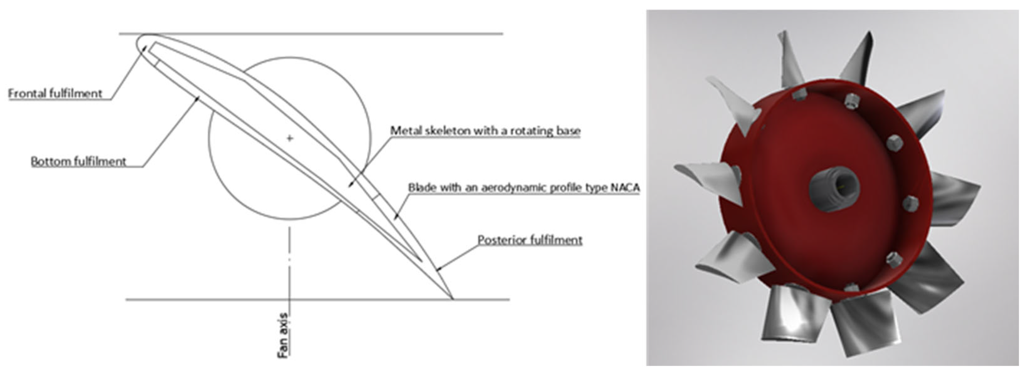
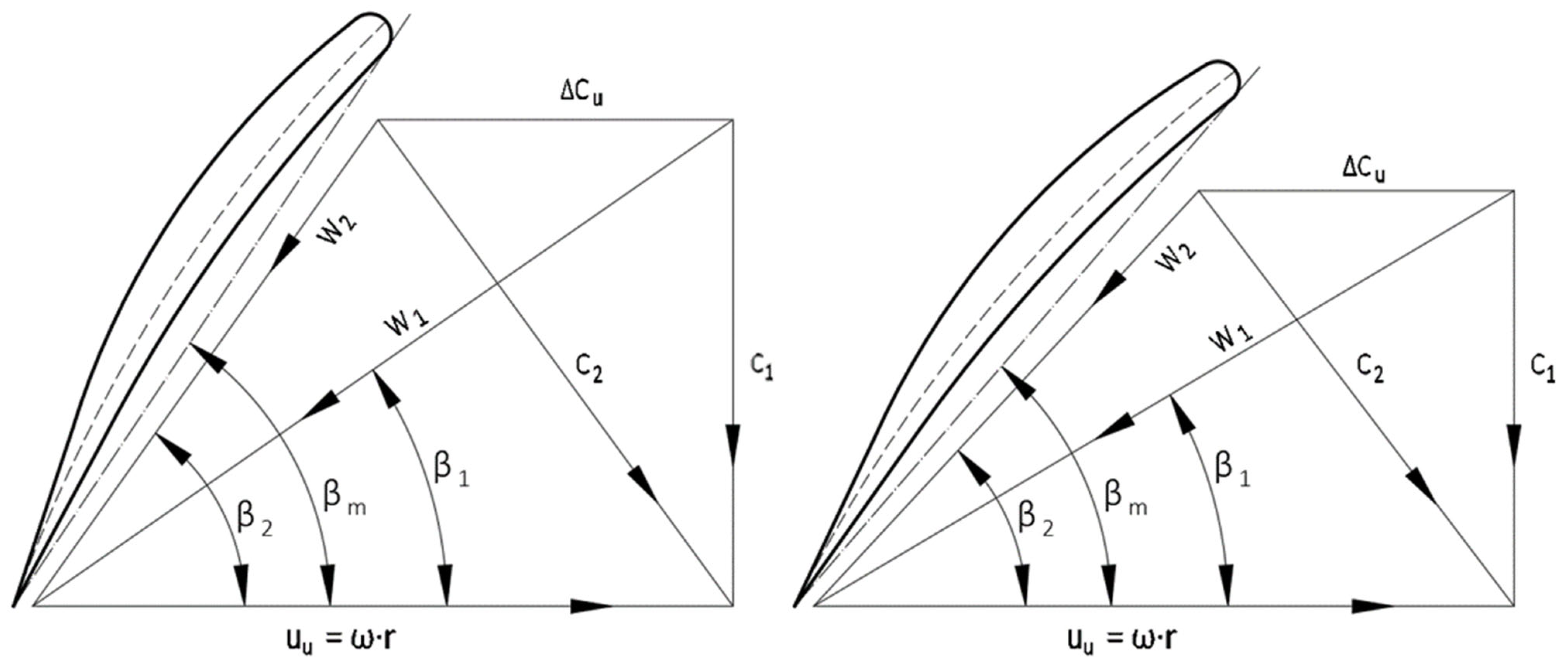
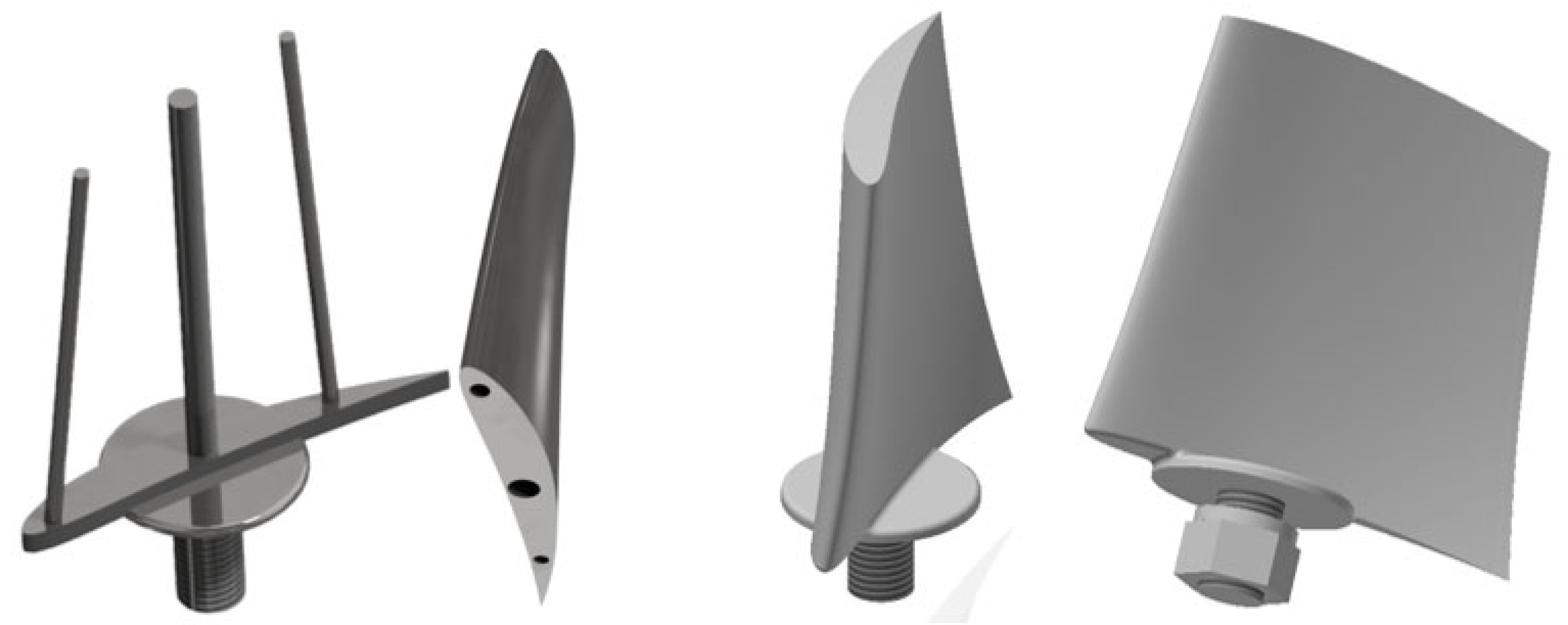
2.1. Designing the Geometric Parameters of the Blade

Based on experience gained in the first stage [9], geometrical parameters of the axial 86 palisade of profiles were assumed. Initially, it was decided to use a NACA-type profile [13] with a varying size and the angle of setting for each blade cross-section depending on the height of the cross-section above its base, which gives the visual effect of “twisting” the blade (Figure 3).
Knowing the outer diameter of the rotor (0.748 m) and the diameter of the hub (0.48 m), the height of the blade (0.134 m) was determined. The area between the outer diameter of the rotor and the diameter of the hub was divided into five cross-sections (0.480; 0.547; 0.614; 0.681; 0.748 m), for which systems of the blade rim velocity vectors were determined.
Depending on the distance of a given blade cross-section from the center of the rotor, the linear velocities of the sections will be lower at the base of the blade and higher at the tip of the blade, which results in the need to design a twisted blade. Figure 4 shows two sections of the blade: near its base on the left and near its center on the right. βm is the inclination angle of the blade chord relative to the rotor’s rim, and β1 and β2 are the angles of inclination of relative gas stream velocities W1 and W2. C2 is the absolute speed behind the rotor, changed relative to C1 as a result of the spin (∆CU) increasing in proportion to the peripheral velocity (u), which depends on the radius (r). As a result, by analyzing individual cross-sections, angles βm for several cross-sections are determined, which in turn will determine the twisting of the blade [1,7,10,14,15]. When designing the geometric parameters of the blade, it should be assumed that the increase in total pressure along the height of the blades is constant [16,17,18]. If the pressure increase condition is not met, radial force components may appear that would be contrary to the axial fan operation assumptions and would negatively affect the efficiency; therefore, when designing the rotor blades for the assumed nominal rotational speed, the angle of attack should be kept constant even though the circumferential speed increases with the radius, whereby the angles β1 (inlet) and β2 (outlet) of the blades are different in each cross-section. The angles β1 and β2 are determined on the basis of the angles of the air stream acting on a given section of the blade, which results from the axial velocity of gas and circumferential velocity [1,7,10,11,12].
On the basis of the calculated air flow velocity and the calculated circumferential velocities for several blade cross-sections, depending on their distance from the center of the rotor, angles of attack of the blades were predetermined and the outlines of the NACA-type profiles were pre-selected [14].
After preliminary analysis, three cross-sections were selected (Figure 5), which were then subjected to numerical simulation (CFD). The cross-sections were tested for different velocities of the incoming air stream at different angles of attack. In order to select the optimal profile, the ratios of lift-to-drag were compared for each profile at a given velocity and air inflow angle [15].
Table 2 presents forces for three types of profiles: quasi symmetrical, concave–convex and concave–convex with a curvature that is an arc of a circle. The last type of the “Plate” profile most closely reflects the existing solutions based on blades shaped from a sheet of metal (datum profiles of blades). This profile also has the highest resistance force and the lowest ratio of the lifting force to the resistance forces, despite the fact that the lifting force of the profile is greater than the symmetrical profile.
The quasi-symmetrical profile NACA 63415 has the lowest lift and the lowest drag force. The concave–convex profile NACA 6412 (Figure 6) has the highest lift and drag force similar to the quasi-symmetrical profile, which allows achieving a very high ratio of lift-to-drag [16,17,18,19,20]. Comparing the 6412 and Plate profiles (Figure 7), the lift/drag ratio is twice as high, despite the similar values of lift forces. Table 3 presents the profile coefficient (Lift/Drag) depending on velocity and angle, for the NACA 6412 profile. As we can see in the case of the NACA 6412 profile, the Lift/Drag coefficient, regardless of Velocity and Angle, is much higher than the other profiles, including Plate (datum profiles of blades).

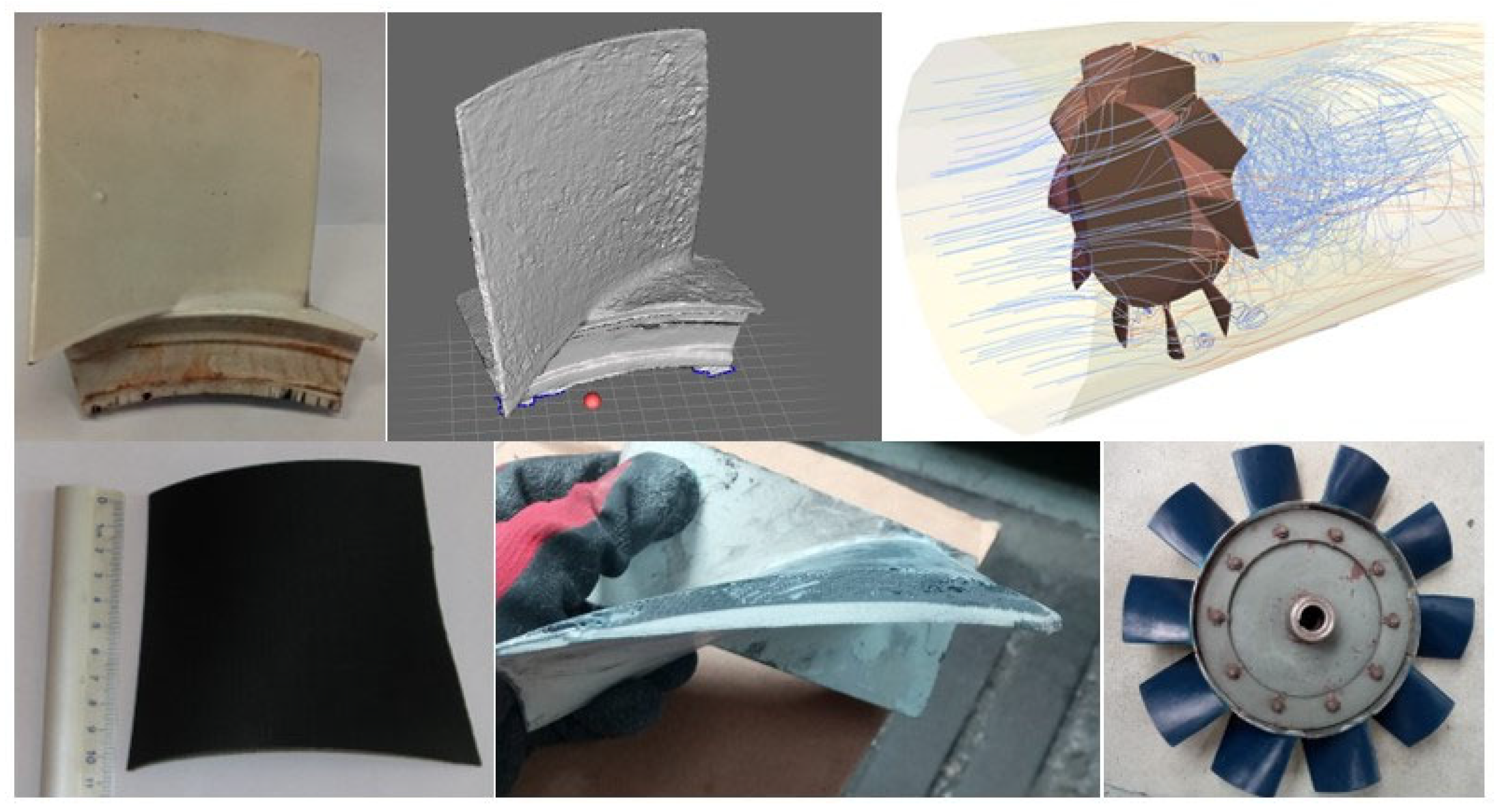
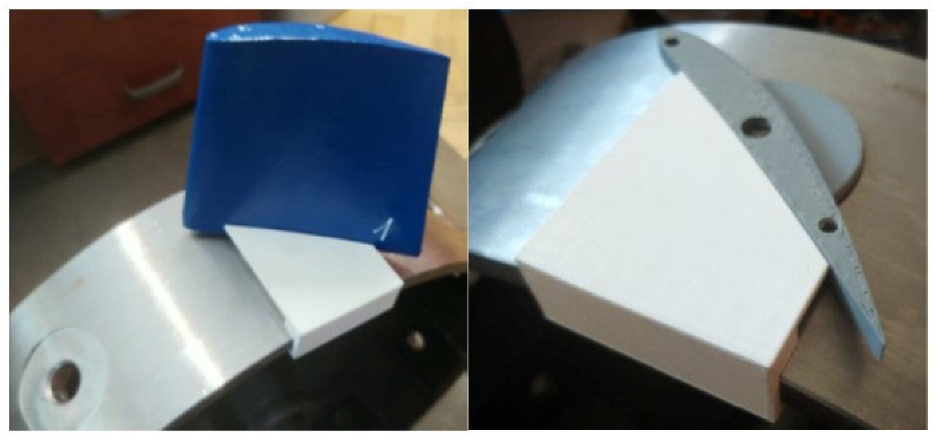
2.2. State-of-the-Art Prototyping Methods

In the presented case, state-of-the-art tools were used to support the rapid prototyping process and to optimize the geometric form of the prototype. These tools include the following:
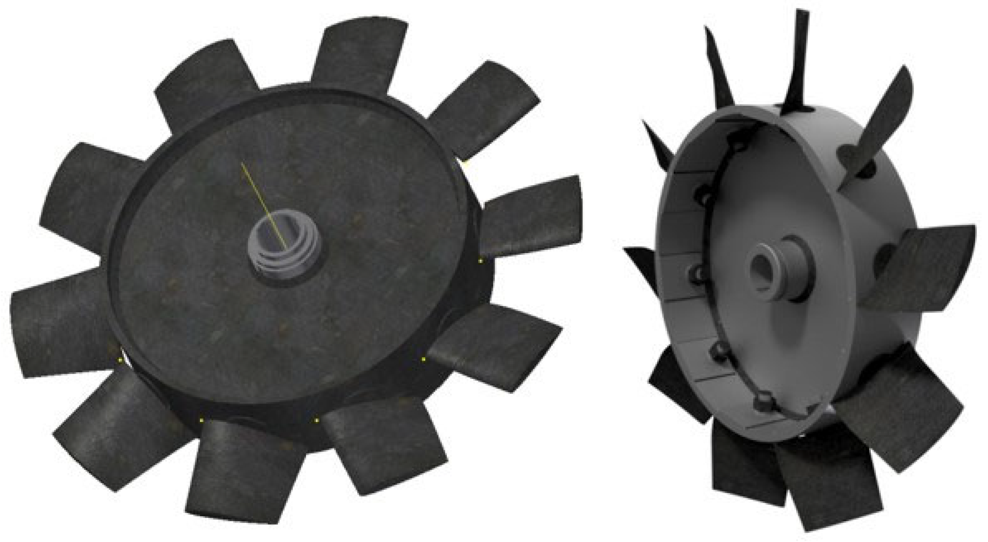
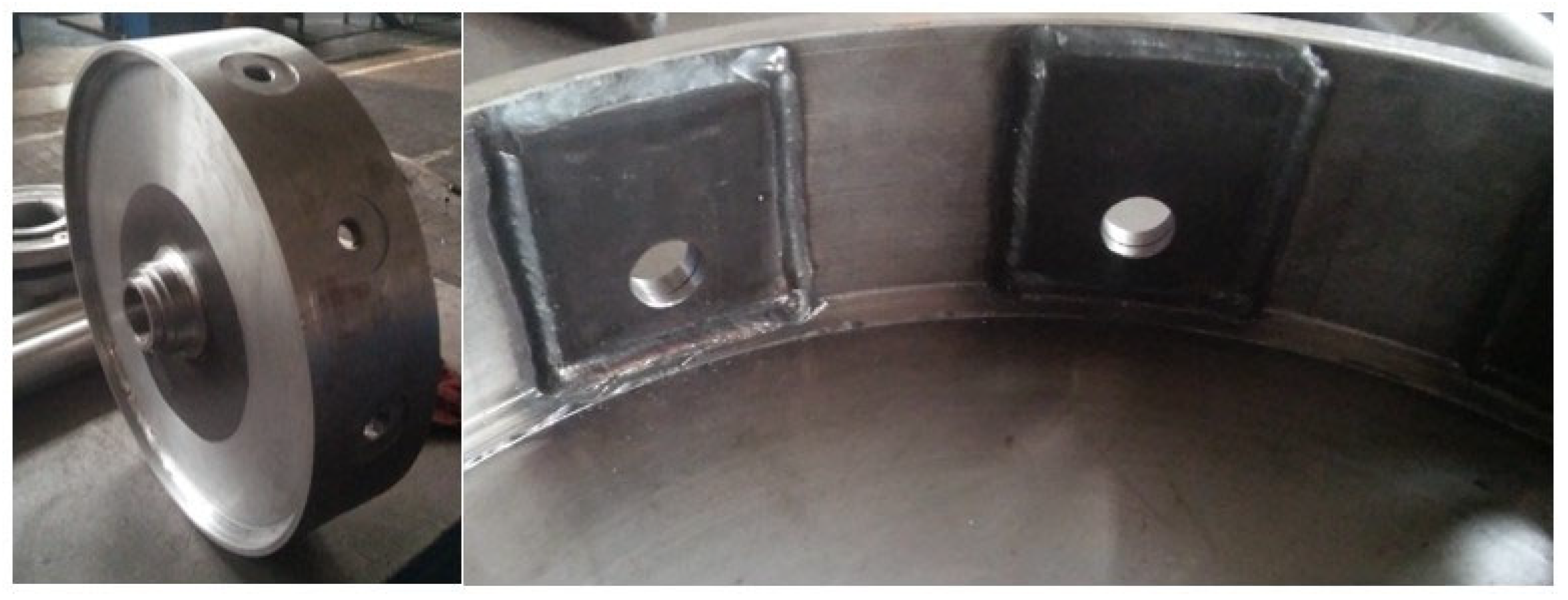
  • 3D scanning of existing rotor components for the purpose of optimizing their geometric form (the first stage of work in an earlier article [9]);
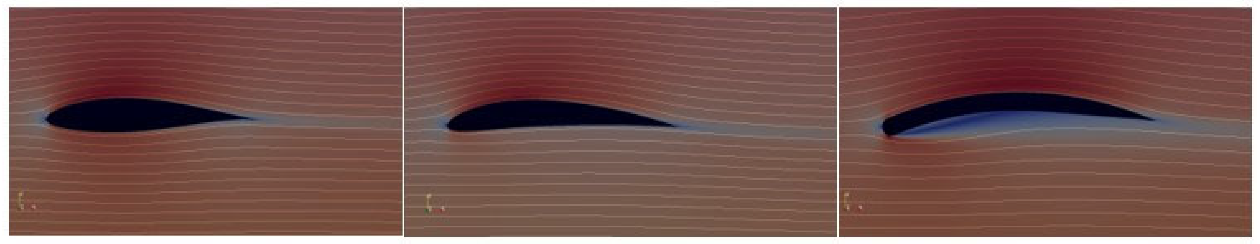
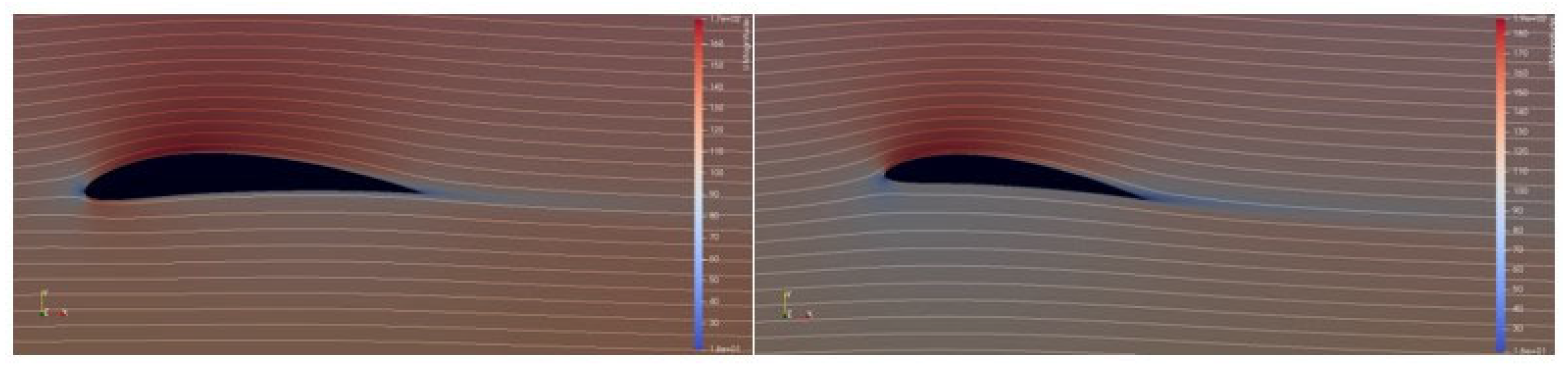
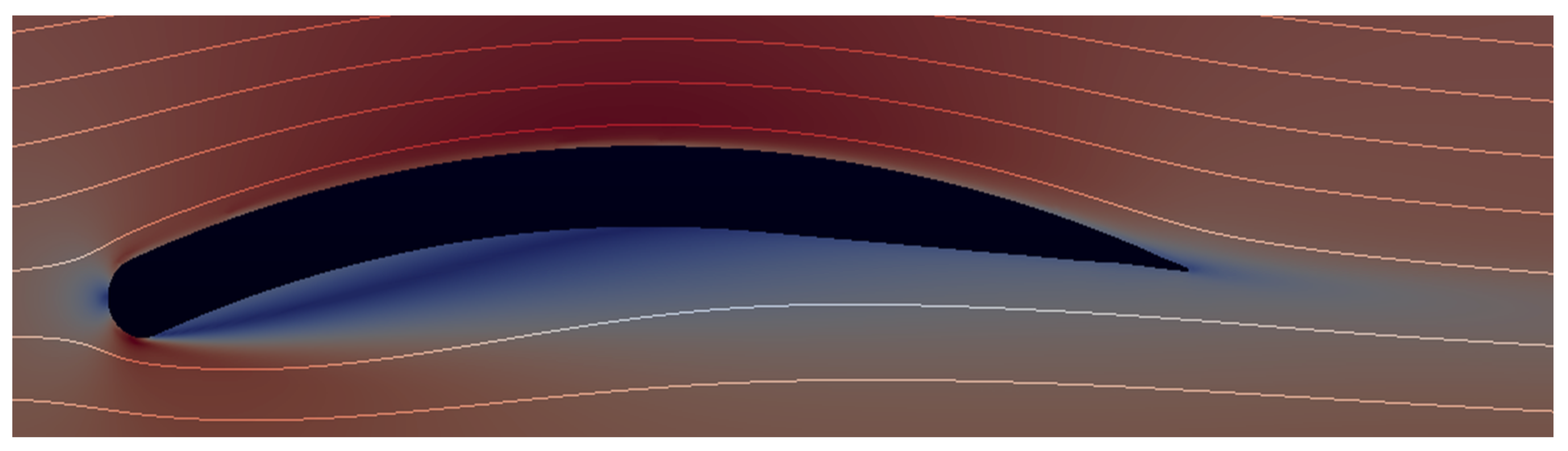
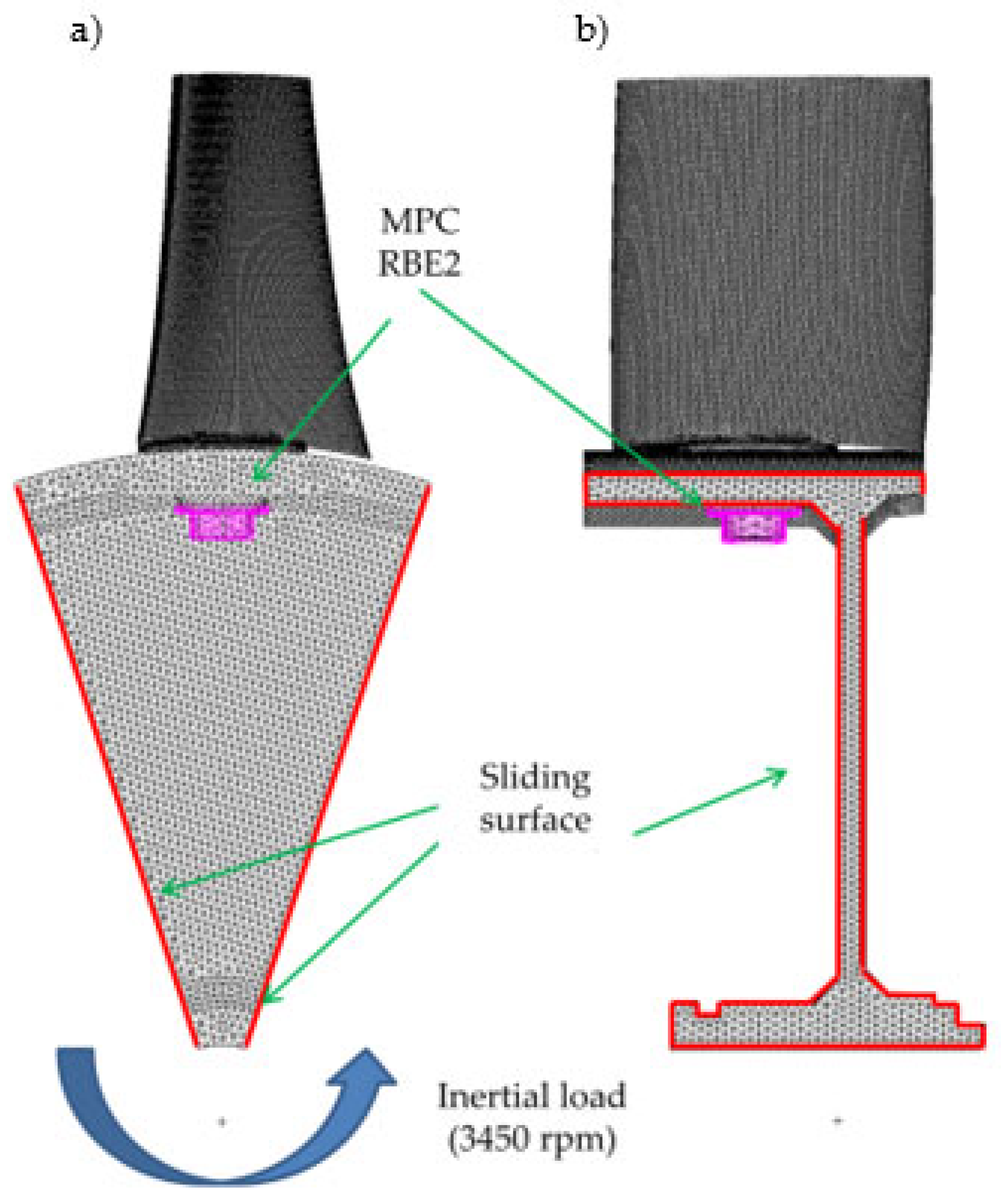
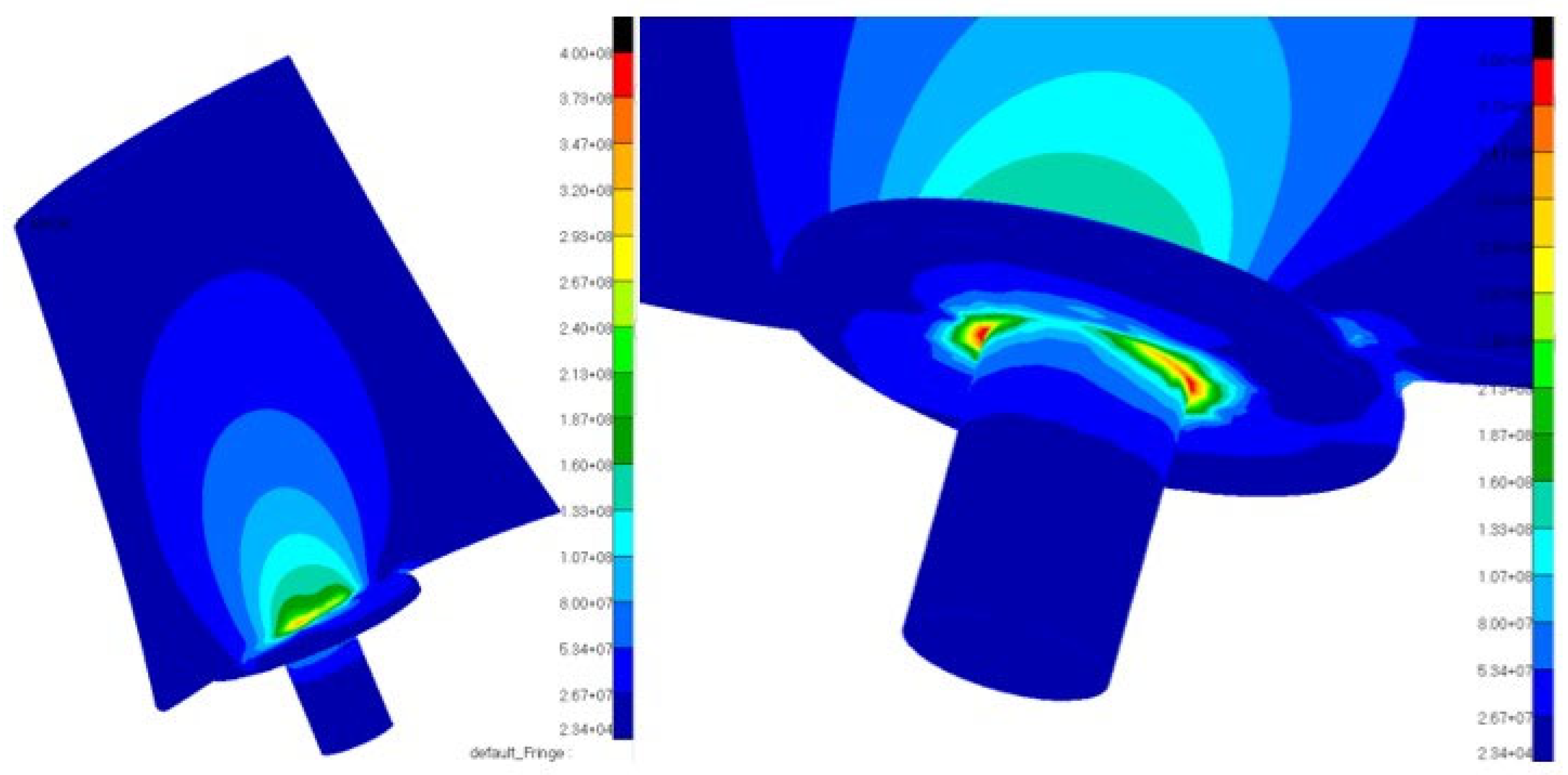
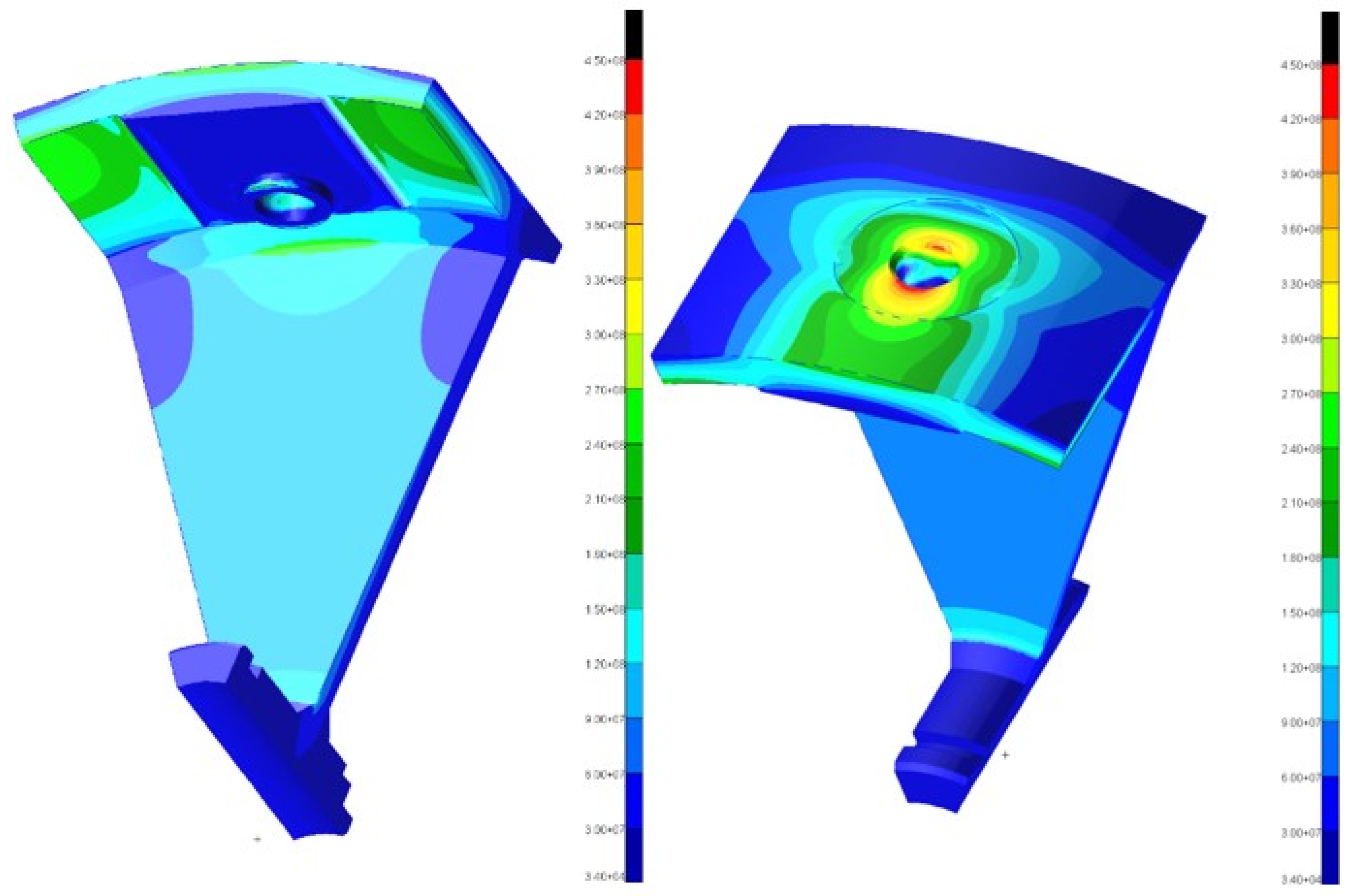
  • CFD and FEM (finite element method) numerical simulations to verify the assumptions and further optimization;
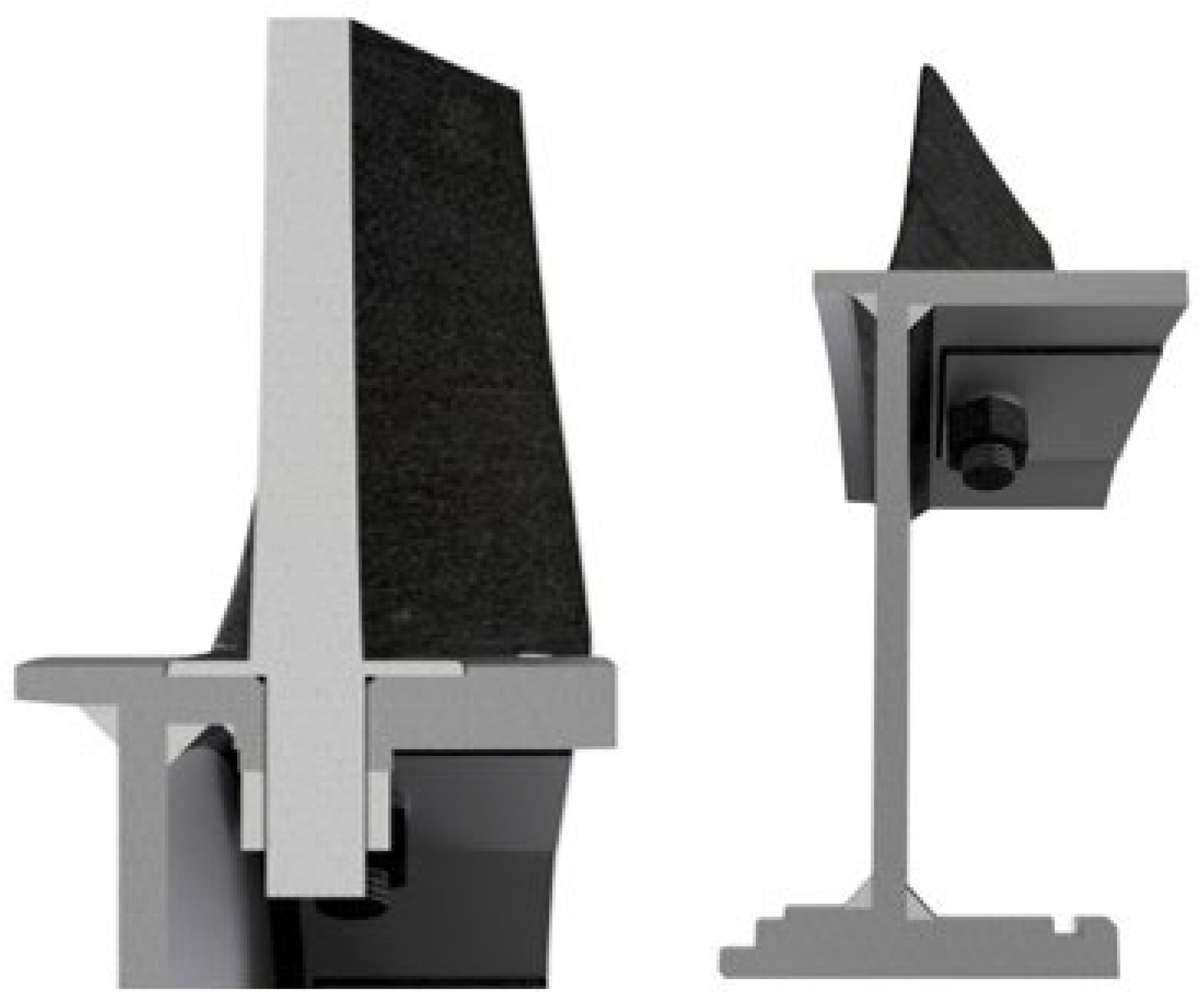
  • Additive manufacturing techniques to build a prototype for stand tests.
3D scanning creates a cloud of points forming the image of real objects in a computer environment. Based on the points, it is possible to define planes, which allows for quickly modifying the existing structural form, adapting it to new requirements or conducting work aimed at optimisation of a given part. Creating a cloud of points can be done with the use of a laser or optical scanner or by using the photogrammetry technique in which it is possible to build a model made of a cloud of points on the basis of properly taken photos. In the example shown (Figure 1), a handheld laser scanner was used [9].
CFD numerical simulations are complex simulations used to simulate fluid dynamics. They are conducted using specialized software such as Ansys Fluent or Altair Acusolve. On the basis of CFD calculations, it is possible to draw conclusions about the distribution of pressures in each place of the computational model, it is possible to observe the “arrangement” of velocity vectors (their location, value, direction and sense), and it is possible to observe changes in the temperature of both liquids and solids [21,22,23,24,25]. Based on the analysis of the calculation results, it was possible to optimize the geometric form of the fan blades. In the present case, the computational model and boundary conditions were as follows: CFD mesh resolution in the near profile area: 5e-4 m; Flow velocity: 85 m/s; type of pressure: far-field (freestream); type of analysis: steady state; turbulence model: Shear Stress Transport (SST); convergence tolerance for pressure and velocity: 0.001. The set of the following software tools was used to carry out the simulation and results analysis: MSC. Patran as a 2D mesh generator, OpenFoam as a solver and ParaView as a post-processor.
On the basis of CFD numerical simulations and graphs provided by [12,13], the modified shape of the blade was selected. The selected NACA 6412 profile has a favourable drag/lift ratio. The blade prepared as a result of rapid prototyping consists of the base created of five welded and bolted steel elements and a 3D printed part (Figure 8 and Figure 9).
The use of various technologies enabled creating a design that is quite light and cheap in prototyping at a low cost in relation to cast technologies or milled with a five-axis machine. The blades were designed in a way that their angle can be adjusted on the rotor hub, one by one, without the need to dismantle the rotor.
FDM (Fused Deposition Modelling) was used to quickly and inexpensively obtain complex-shaped blades ready for testing. The ZOLTRAX M200 3D printer was used. In order to ensure the appropriate properties and the appropriate quality of 3D printed elements, the model was prepared by specialists in dedicated software (Z-SUITE) before printing. During the printing preparation, a number of parameters were defined, including: the thickness of a single printing layer (0.19 mm with High Quality parameter), the temperature of the nozzle (~250 °C) and the working table (~60 °C) (they are selected for the material used), the printing speed (36 mm/s), the degree of filling (60%) and its type, and the way the model is arranged on the working table (vertical). The 3D-printed rotor blade elements were made of the popular ABS (acrylonitrile butadiene styrene) plastic. The structure of the printed element was prepared in such a way that it could be combined with a metal base and a steel core, which created a full model of the rotor blade. The use of such a solution resulted in an increase in the strength of the prototype rotor blades and also eliminated the problem of excessive weight of a single blade made only of solid steel [26]. To obtain a uniform and smooth surface of the blades, their surface was smoothed with fine-grained sandpaper, and then a thin layer of varnish was applied.
The use of a blade with a variable angle of attack required the special design of a rotor blade. The rotor is equipped with 10 sockets with holes enabling the blades to be placed in them in various positions. The blades were attached to the rotor disc by means of screw joints.
Based on the 3D geometrical model, a FEM [27] computational model was developed in the MSC.Patran [28] software environment. The second order of tetrahedral solid elements (TETRA10) was used during the discretization process. TETRA10 solid elements ensure high accuracy of calculation results with an acceptable length of calculation time. In order to avoid degeneration of finite elements and low quality of results, the number of TET10 elements on the thickness of the outer flange of the rotor hub was increased to 5. The total number of nodes was over 750,000. The finite element meshes of the rotor hub and blade were connected using the multi-point constrains elements (MPC type RBE2): the cylindrical surface of the blade (in the physical object it is threaded) with the recessed surface of the inner side of the rotor, Figure 10. A partial 3D model was used due to its periodic symmetry. Gas load (pressure) was not included into the computational model because of its negligible impact on the obtained results. The decision was based on the analysis of previous simulation results.
As a result of the high rotational speed of the rotor at 3450 rpm, stresses arise in the blade and in the place where it is fixed in the hub. The results of the FEM analysis regarding the blade are presented in Figure 11, and the analysis regarding the place of its mounting on the hub is shown in Figure 12. The results indicate in red the maximum stress of 400 MPa, and therefore the steel sheet for the rotor structure should have a yield strength of at least 450 MPa. Due to the high complexity of the blade structure, it was simplified in FEM calculations as a homogeneous structure as shown in Figure 13.
In the final stage, the outer part of the rotor hub was machined in order to obtain an even gap between the blades and the fan body, and was balanced to eliminate unnecessary vibrations of the rotor, which could adversely affect its durability. Figure 14 shows the metal rotor to which the blades will be attached. Figure 15 shows a comparison of the new (left) and datum (right) rotor design.

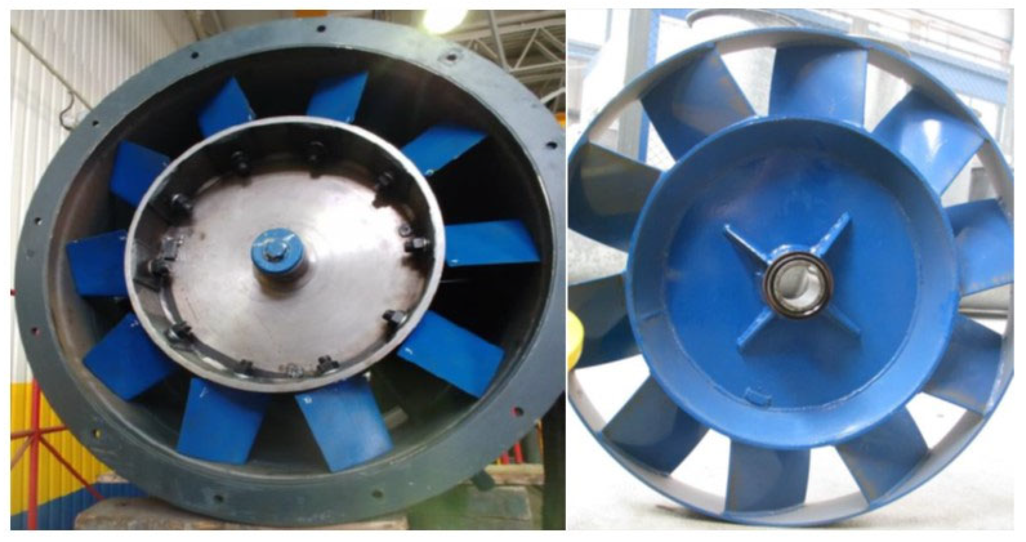
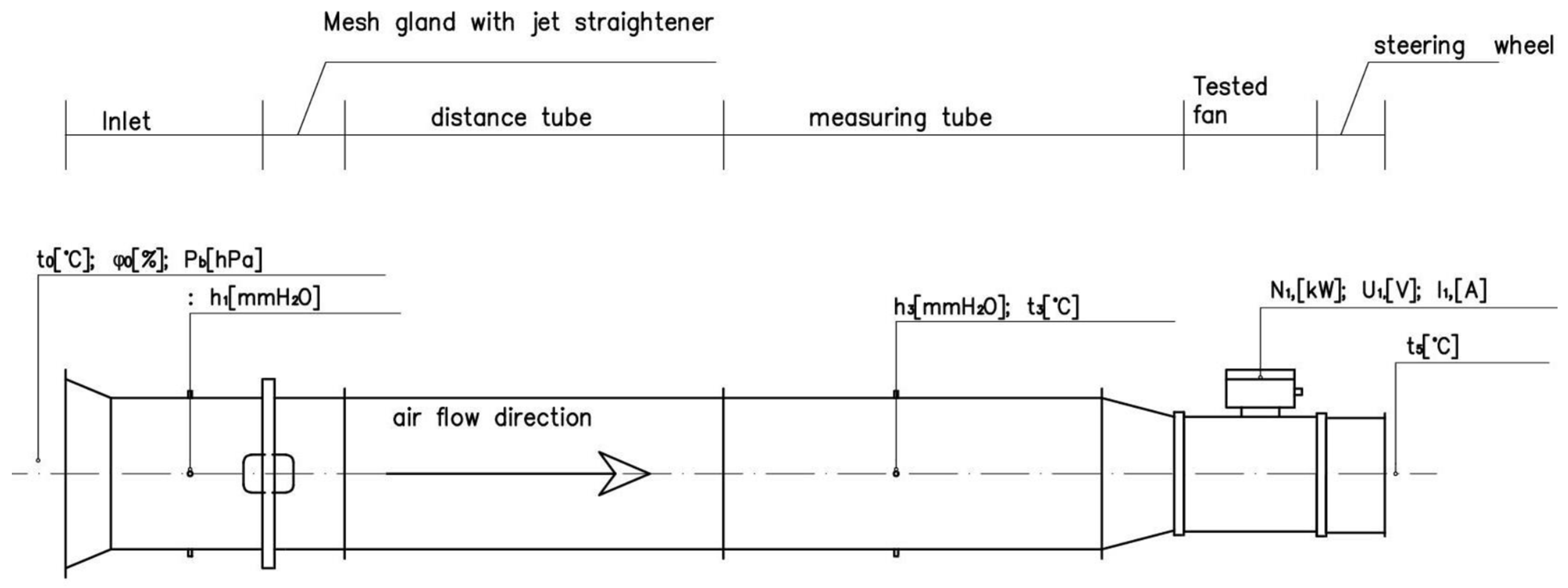
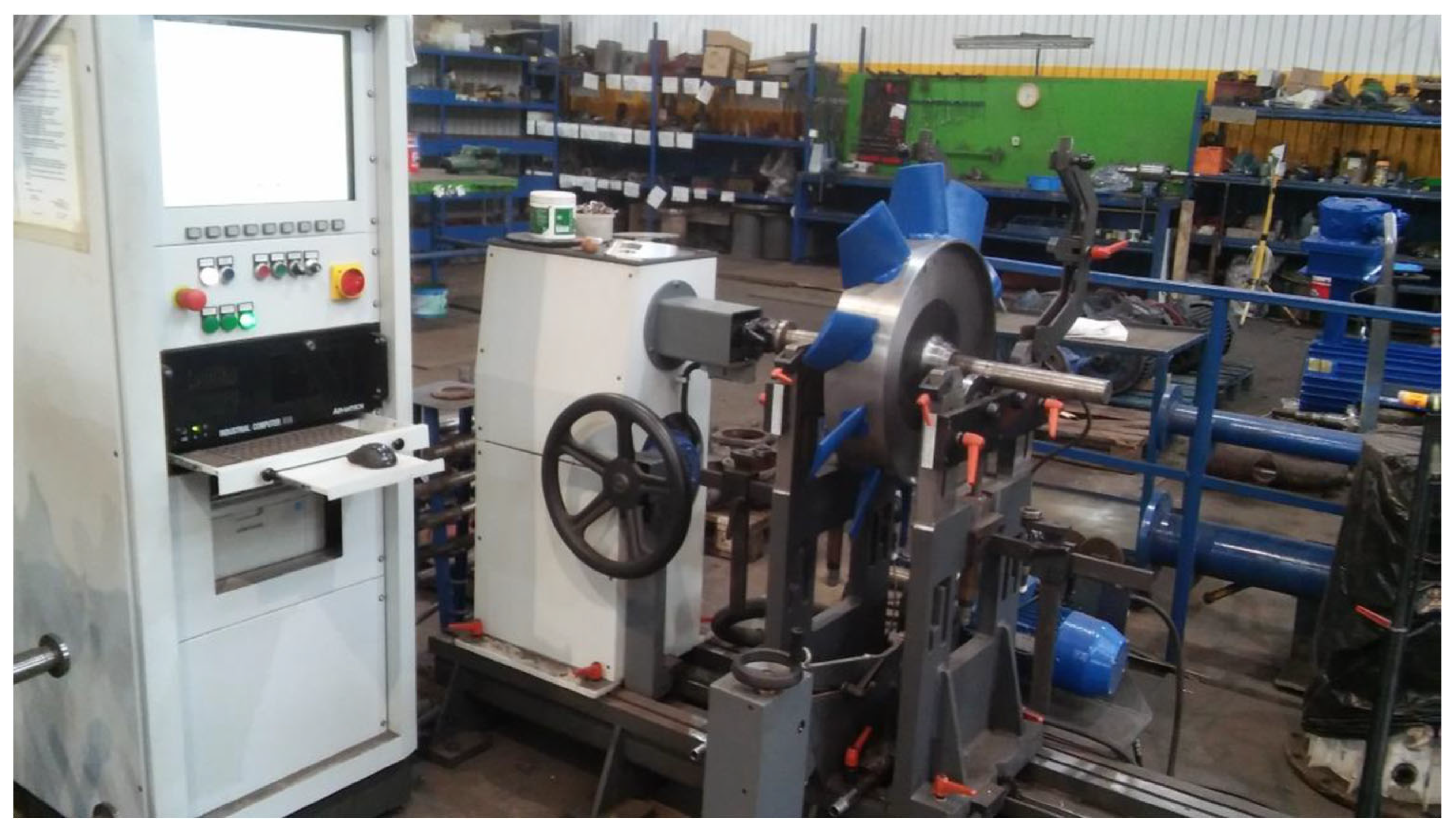
2.3. Testing the New Rotor
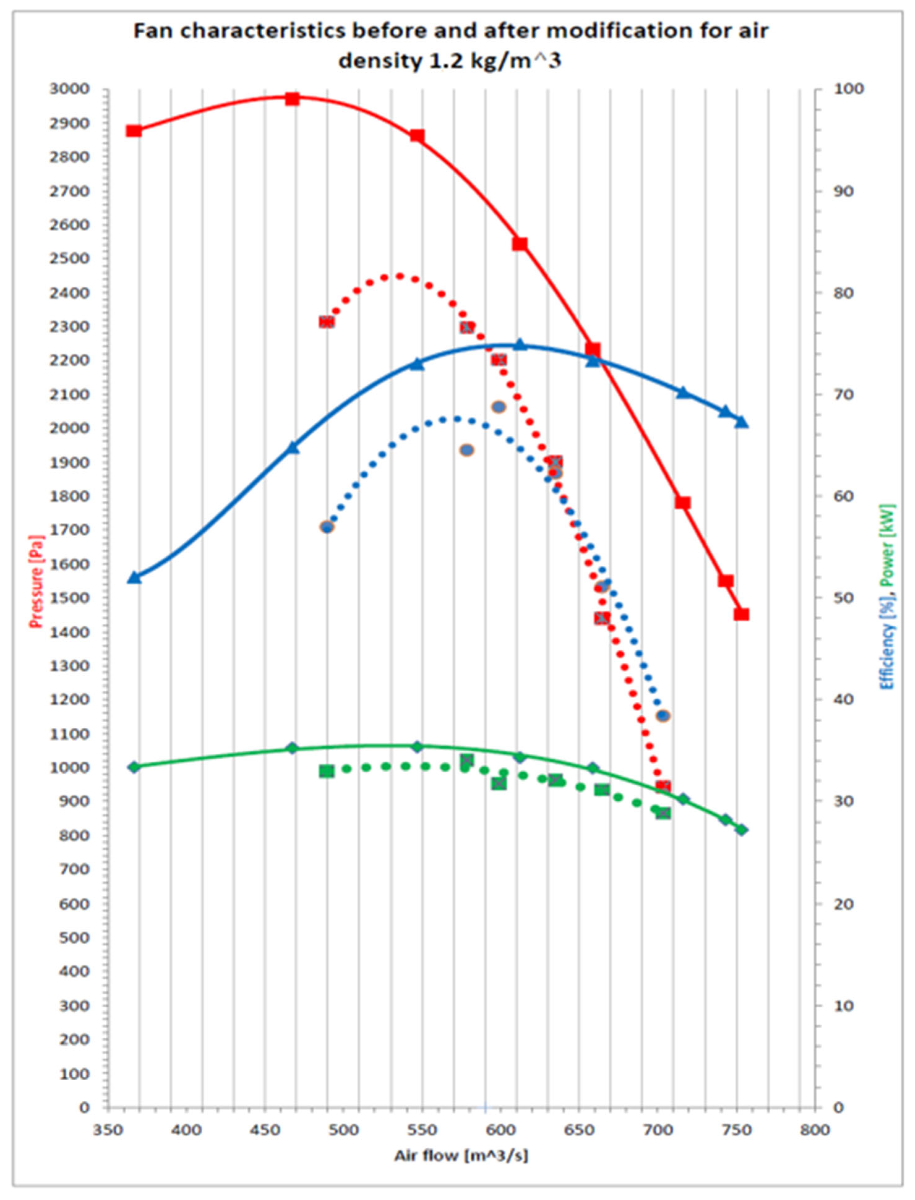
On the measuring stand, according to the diagram shown in Figure 16, tests were carried out to determine the fan operation characteristics. The stand was built inside the hall so as to obtain repeatability of results and reduce the impact of weather conditions on the test results [29]. The experimental determination of the characteristics of duct fans should be carried out on standardized test stands. According to the [30] standard, four types of test stands are distinguished: type A (free inlet and free outlet from the fan), type B (free inlet, channel on the outlet side from the fan), type C (duct on the fan inlet side, free outlet), type D (ducts on the inlet and outlet sides from the fan). The type C station best reflects the actual operation of the fan (the fan works with the dust extraction device in the suction system). The tests consist of invoking and increasing the fan throttling value and recording for each state: temperature and air humidity (thermohygrometer TESTO 605), atmospheric pressure (KESTREL 4000 multifunctional device), negative pressure in front of the fan corresponding to the fan’s back pressure (Askania-type water micromanometer), values of electrical parameters of the current supplying the electric motor: power, voltage and current (AR-5 network parameter register).
In the measuring duct, a mesh gland with a flow straightener was built in, in which the hydraulic resistance was changed. The flow conditions, in which no mesh was placed in the stuffing box, corresponded to the highest air flow of the fan (extreme “right” point). As successive meshes were added, the air flow of the fan decreased, and the pressure rose, until reaching the maximum point, beyond which the fan entered the pumping state. The fans were tested until the pressure increase on the pump side of the characteristic was obtained, which corresponded to the extreme “left” point of the characteristic.
A fan equipped with a new rotor was tested in the stand. The rotor is characterized by the ability to change the blade angle, so that it was possible to change the fan parameters. In order to be able to accurately determine the angle of the blade, a blade-positioning element was made using 3D printing (Figure 17). The rotor with the modified blades was balanced and reinstalled in the fan, which was tested on the test stand (Figure 18).
During the first tests, the blades were set at the optimal calculated angle; the subsequent tests included an angle change of ±5°. Characteristics of the datum rotor were determined during previous tests carried out on the same type “C” test bench. A chart comparing the characteristics of both fans is shown in Figure 19.

3. Results

The tests clearly indicated the rightness of using the airfoil profile in the blades of mine fans. Table 4 and Figure 19 show the test results before and after modification.
The recorded values are recalculated accordingly with the calculation procedures given in the standard [30] and in the literature [1,3], to the reduced values for standard air density (1.2 kg/m3): air flow, pressure, efficiency and power with scatter resulting from measurement errors (±5%). In the case of comparative tests carried out using the same measuring devices and the same type of station, the measurement error can be considered negligible.
Figure 19 shows a graph with the pressure (red line), efficiency (blue line) and power (green line) functions depending on the air flow. The curves of the characteristics were obtained by estimating the calculated values using the least squares method, approximating the relationships presented in the characteristics with polynomial functions.
The nominal parameters of the fan are efficiency and pressure rise, which determine the point on the fan’s characteristics where its operation is most effective in terms of energy.
The red line shows a significant increasing of the pressure, in the optimal operating point, as well as a slight improvement in efficiency in the range of stable fan operation. The power consumed by the fan slightly increased compared to the datum solution; however, the permissible power for the installed motor with a nominal power of 37 kW was not exceeded.

4. Conclusions

As it can be seen in Figure 19, the use of a new rotor in the WLE 1013B fan of 37 kW power increased its efficiency in the nominal point by 8%. The improved fan offers the pressure 2500 Pa at the nominal operational point with an efficiency of 75% in relation to the datum fan with pressure 2200 Pa and efficiency 66.8%. A more “flat” efficiency curve (within the entire range of fan operation) was obtained with increased pressure Pa and air flow m3/s. The improvement in efficiency was achieved by using a more effective blade profile (NACA 6412) with a high Lift/Drag coefficient and selecting the optimal blade angle in the rotor. The research work shows a positive effect of using the chosen concave–convex profile with varying thickness. The previous blade, of simplified structure, bent from steel sheet, with only a sharpened trailing edge is less effective, which can be explained based on the mechanism of operation of such a simplified blade, although the pressure-difference generation is similar but is very imperfect due to the constant thickness. The air stream moves along the shortest path; however, the swirls are created at the concave surface of the blade and interfere with the linear flow of the stream. One more circumstance, which contributed to obtaining a better result compared to the previous blade should also be mentioned. The new blades were accurately smoothened and then painted, which significantly reduced the roughness of the surface responsible for the linear flow of the air stream, so the proposed profile is also less susceptible to detachment of the stream from the blade profile in the event of an air-flow velocity change.
Auxiliary fans in the underground workings operate in a nominal point only during a part of the time. A fan’s point of operation is selected regarding the maximum resistance of the ventube duct. In practice, the driven roadway reaches its nominal length only at the end of planned work, so the fan operational parameters are beyond the nominal point of its characteristics. The new rotor, due to the optimized design of blades, has high efficiency from zero network resistance to the nominal point of operation. Power reserve for the case of operation at a pressure higher than nominal was maintained.

Author Contributions

Conceptualization, M.S. (Michał Szelka), A.D. and J.T.; methodology, M.S. (Michał Szelka); software, K.S.; validation, M.B., K.K. (Krzysztof Kołodziejczyk) and K.K. (Krzysztof Kędzia); formal analysis, K.K. (Krzysztof Kędzia); investigation, K.S.; resources, M.S. (Marek Szyguła); writing—original draft preparation, M.S. (Michał Szelka) and A.D.; writing—review and editing, M.S. (Marek Szyguła); visualization, J.T.; supervision, M.B. All authors have read and agreed to the published version of the manuscript.

Funding

The article was written as part of the work carried out under the European project INESI, “Increase efficiency and safety improvement in underground mining transportation routes”. This project received funding from the Research Fund for Coal and Steel under grant agreement No 754169. The article was written as part of the work carried out under the AGH University of Science and Technology: IDUB No. 501.696.7997, Faculty of Mechanical Engineering and Robotics: subvention No. 16.16.130.942. (European Commission: 754169 and AGH IDUB No. 501.696.7997).

Institutional Review Board Statement

Not applicable.

Informed Consent Statement

Not applicable.

Data Availability Statement

Not applicable.

Conflicts of Interest

The authors declare no conflict of interest.

References

  1. Fortuna, S. Wentylatory: Podstawy Teoretyczne, Zagadnienia Konstrukcyjno-Eksploatacyjne i Zastosowanie; Techwent: Kraków, Poland, 1999. [Google Scholar]
  2. Bleier, F.P. Fan Handbook: Selection, Application and Design; McGraw-Hill Education: New York, NY, USA, 1997; ISBN 9780070059337. [Google Scholar]
  3. Bieniek, C. Wentylatory Osiowe; WNT: Warszawa, Poland, 1961. [Google Scholar]
  4. Łazarkiewicz, S. Pompy Sprężarki Wentylatory; PWT: Warszawa, Poland, 1957. [Google Scholar]
  5. Tuliszka, E. Sprężarki, Dmuchawy i Wentylatory; WNT: Warszawa, Poland, 1969. [Google Scholar]
  6. Czechowicz, J. Wentylacja Lutniowa w Kopalniach; Wydawnictwo Şląsk: Katowice, Poland, 1977. [Google Scholar]
  7. Pascu, M.T. Modern Layout and Design Strategy for Axial Fans. Ph.D. Thesis, Friedrich-Alexander-Universitaet Erlangen-Nuernberg, Erlangen, Germany, 2009. [Google Scholar]
  8. INESI Project Site. Available online: http://inesi.komag.eu/ (accessed on 7 November 2022).
  9. Drwięga, A.; Szelka, M.; Turewicz, A. Rapid prototyping axial fan blades. Masz. Górnicze 2019, 37, 27–36. [Google Scholar] [CrossRef]
  10. Eck, B. Ventilatoren; Springer: Berlin, Germany, 1972; ISBN 978-3-662-30211-8. [Google Scholar]
  11. Bohl, W. Axialventilatoren. In Berechnung und Entwurf von Ventilatoren; Vulkan-Verlag: Essen, Germany, 1955. [Google Scholar]
  12. Szelka, M.; Drwięga, A.; Tokarczyk, J.; Feifer, J.; Kowalczyk, A.; Woszczyński, M.; Jagoda, J.; Zeleznik, G. Deliverable: D5.3 Report from Field Trials of Low Energy Consumption Ventilation System; Gliwice, Poland, 2020; Unpublished work. [Google Scholar]
  13. Jacobs, E.N.; Ward, K.E.; Pinkerton, R.M. NACA Report No. 460, "The Characteristics of 78 Related Airfoil Sections from Tests in the Variable-Density Wind Tunnel"; NACA: USA, 1933; Available online: http://ftp.demec.ufpr.br/disciplinas/TM045/Report460_1935.pdf (accessed on 1 November 2022).
  14. Airfoiltools. Available online: http://airfoiltools.com/ (accessed on 7 November 2022).
  15. Beristain, I.G. Aerodynamic Analysis of Axial Fan Unsteady Simulations; University of the Basque Country: Leioa, Spain, 2012. [Google Scholar]
  16. Velazquez Salazar, O.E.; Morency, F.; Weiss, J. Predicting Maximum Lift Coefficient for Compound Wings Using Lifting Line Theory. J. Aircr. 2021, 58, 717–732. [Google Scholar] [CrossRef]
  17. Phillips, W.F.; Hunsaker, D.F.; Joo, J.J. Minimizing Induced Drag with Lift Distribution and Wingspan. J. Aircr. 2019, 56, 431–441. [Google Scholar] [CrossRef]
  18. Kuczewski, S. Wentylatory; WNT: Warszawa, Poland, 1978. [Google Scholar]
  19. Arżnikow, N.S. Aerodynamika; PWN: Warszawa, Poland, 1959. [Google Scholar]
  20. Eckert, B. Srężarki Osiowe i Promieniowe; PWT: Warszawa, Poland, 1959. [Google Scholar]
  21. Carolus, T. Ventilatoren. Aerodynamischer Entwurf, Konstruktion; BG Teubner Verlag: Stuttgart, Germany, 2003; ISBN 3834824712. [Google Scholar]
  22. Schlender, F. Ventilatoren im Einsatz; VDI Verlag: Berlin, Germany, 1996; ISBN 978-3-540-62132-4. [Google Scholar]
  23. Panigrahi, D.C.; Mishra, D.P. CFD simulations for the selection of an appropriate blade profile for improving energy efficiency in axial flow mine ventilation fans. J. Sustain. Min. 2014, 13, 15–21. [Google Scholar] [CrossRef]
  24. Anderson, J.D. Computational Fluid Dynamics: The Basics with Applications; McGraw-Hill: New York, NY, USA, 1995; ISBN 0071132104. [Google Scholar]
  25. Carcangiu, C.E. CFD-RANS Study of Horizontal Axis Wind Turbines. Ph.D. Thesis., Department doing genera mechanical, University deg li Studi di Cagliari, Cagliari, Italy, 2008. [Google Scholar]
  26. Michalak, D.; Herrero, J.A.G. Innovative solutions need an innovative approach—3D printing technology, example of use and conclusion from implementation in an organization. Min. Mach. 2020, 2, 48–57. [Google Scholar] [CrossRef]
  27. Zienkiewicz, O.C.; Taylor, R.L.; Zhu, J.Z. The Finite Element Method: Its Basis and Fundamentals, 7th ed.; Butterworth-Heinemann: Oxford, UK, 2013; ISBN 9781856176330. [Google Scholar]
  28. Patran Complete FEA Modeling Solution. Available online: https://www.mscsoftware.com/product/patran (accessed on 6 October 2021).
  29. Dz.U. 2017 poz. 1118. Rozporządzenie Ministra Energii z Dnia 23 Listopada 2016r. w Sprawie Szczegółowych Wymagań Dotyczących Prowadzenia Ruchu Podziemnych Zakładów Górniczych, Rozdział 3 Przewietrzanie za Pomocą Lutniociągów, Pomocniczych Urządzeń Wentylacyjnych lub Przez Dyfuzje. (26. Journal of Laws 2017. Item 1118 Regulation of the Minister of Energy of November 23, 2016. on Aid for the Conduct of Traffic below the Main Mines, Chapter 3 Ventilation by Air Ducts, Auxiliary Ventilation Devices or by Diffusion). Available online: https://isap.sejm.gov.pl/isap.nsf/DocDetails.xsp?id=WDU20170001118 (accessed on 7 November 2022).
  30. PN-EN ISO 5801:2017-12; Wentylatory przemysłowe. Badanie charakterystyk działania na stanowiskach znormalizowanych.
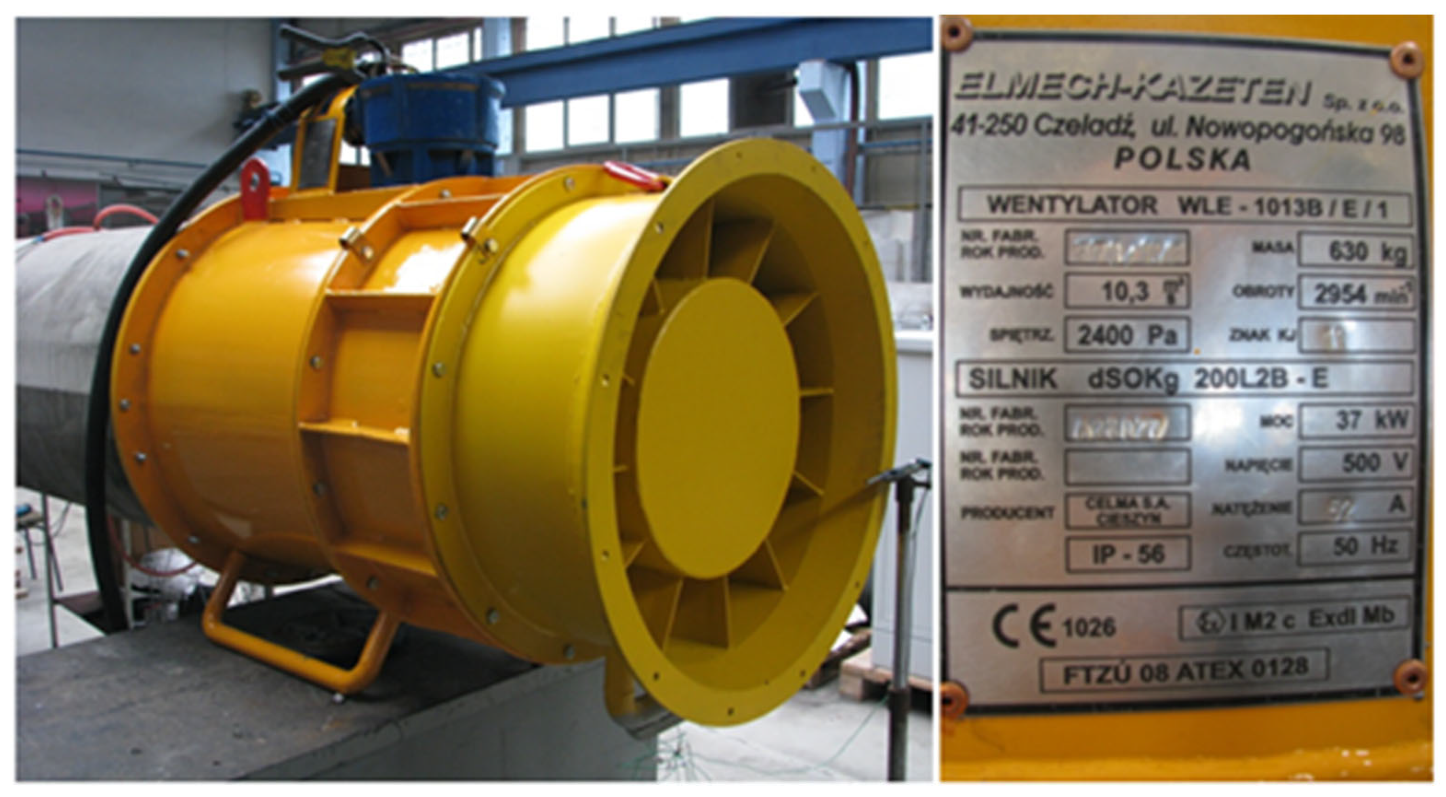
Figure 1. Stages of rotor prototype preparation using state-of-the-art prototyping methods.
Energies 16 00542 g001
Figure 2. Electric axial fan ELMECH-WLE-1013B/E/1 [12].
Energies 16 00542 g002
Figure 3. Conceptual design of the new blade and spatial geometric model of the rotor.
Energies 16 00542 g003
Figure 4. System of velocity vectors for the axial rim cross-section [1].
Energies 16 00542 g004
Figure 5. Illustrative representation of lift generation by 85 m/s entry velocity at zero angle of attack, as a result of different velocities at the top and bottom sides of the profiles for its different types: NACA 63415, NACA 6412 and Plate.
Energies 16 00542 g005
Figure 6. Contour map of the flow velocity (122 m/s) of the NACA 6412 profile from the left: for a zero and a five-degree angle of attack of the profile.
Energies 16 00542 g006
Figure 7. Contour map of flow velocity (85 m/s) of the Plate profile for zero degree angle of attack.
Energies 16 00542 g007
Figure 8. The model of the rotor prepared for analysis.
Energies 16 00542 g008
Figure 9. Metal base of the blade, 3D-printed blade and the complete model of the blade.
Energies 16 00542 g009
Figure 10. Boundary conditions of the computational model: front view (a), side view (b).
Energies 16 00542 g010
Figure 11. Reduced stress map of the blade. The maximum values reach 400 MPa.
Energies 16 00542 g011
Figure 12. Rotor’s reduced stress map. The maximum values reach 235 MPa.
Energies 16 00542 g012
Figure 13. Blade fastening method.
Energies 16 00542 g013
Figure 14. View of the rotor with blades sockets.
Energies 16 00542 g014
Figure 15. Comparison of the new (left) and datum (right) rotor design.
Energies 16 00542 g015
Figure 16. Scheme of the stand for testing the mine fans, type “C”.
Energies 16 00542 g016
Figure 17. Determination of the correct blade angle.
Energies 16 00542 g017
Figure 18. Balancing of the rotor.
Energies 16 00542 g018
Figure 19. Characteristics of the previous (dotted line) and improved (solid line) version of fan.
Energies 16 00542 g019
Table 1. Input data for the blade design process.
Lp.ParameterSymbolValueUnit
1Nominal air flowV10.3m3/s
2Maximum pressurePc2600Pa
3Rotation speedn29401/min
4Air densityρ1.2kg/m3
5PowerN37kW
6Rotor outer diameterDz0.748m
7Hub diameterDw0.48m
Table 2. Values of forces acting on selected profiles with a zero angle of attack at the inflow of a stream at 85 m/s.
ProfileLift [N]Drag [N]Moment [Nm]Lift/Drag
1NACA 634156.220.620.0010.03
2NACA 641213.100.72−0.0218.19
3Plate11.381.210.159.40
Table 3. Values of forces acting on the NACA 6412 profile.
Velocity [m/s]Angle [°]Lift [N]Drag [N]Moment [Nm]Lift/Drag
1122027.341.45−0.0418.85
2122535.231.72−0.4420.48
385013.100.72−0.0218.19
485523.071.06−0.3821.76
Table 4. Comparing the results before and after modification of the rotor.
New BladesAfter Modification
12345678
Power[kW]2728303334353533
Pressure[Pa]14511550178122342543286429712878
Air flow[m3/min]753743716659612547467367
Efficiency[%]67.368.470.273.375.073.064.852.0
Old BladesBefore Modification
12345678
Power[kW]293132323433--
Pressure[Pa]94314411900217322842315--
Air flow[m3/min]703664635590566489--
Efficiency[%]38.451.162.366.862.857.0--
Disclaimer/Publisher’s Note: The statements, opinions and data contained in all publications are solely those of the individual author(s) and contributor(s) and not of MDPI and/or the editor(s). MDPI and/or the editor(s) disclaim responsibility for any injury to people or property resulting from any ideas, methods, instructions or products referred to in the content.

