
Power Converter Solutions for Industrial PV Applications—A Review
by
 , ,
, ,
Ievgen Verbytskyi
1 ,
,
Mykola Lukianov
1,
Kawsar Nassereddine
2,*, 
Bohdan Pakhaliuk
3,
Oleksandr Husev
4,* and
Ryszard Michał Strzelecki
3
1
Igor Sikorsky Kyiv Polytechnic Institute, National Technical University of Ukraine, 03056 Kyiv, Ukraine
2
Faculty of Engineering, Lebanese University, Beirut 1002, Lebanon
3
Department of Power Electronics and Electrical Machines, Faculty of Electrical and Control Engineering, Gdańsk University of Technology, 80-233 Gdansk, Poland
4
Department of Electrical Power Engineering and Mechatronics, Tallinn University of Technology, 19086 Tallinn, Estonia
*
Authors to whom correspondence should be addressed.
Energies 2022, 15(9), 3295; https://doi.org/10.3390/en15093295
Submission received: 4 April 2022
/
Revised: 22 April 2022
/
Accepted: 28 April 2022
/
Published: 30 April 2022
(This article belongs to the Topic Power Converters)
Abstract
:As the use of photovoltaics becomes more widespread, new technologies for more efficient energy generation, transmission, and distribution based on power electronics converters are being developed. The most common applications are grid-on, energy storage, hybrid, and high voltage gain applications. These applications impose several additional requirements in the design of power converters associated with the solar battery’s maximum power tracking and operation in a wide range of input currents and voltages. The practical realization of such solutions can be implemented on the basis of various topologies, which requires a preliminary application of criteria for assessing their effectiveness. The paper conducts a comparison of different topologies on power converters based on two parameters that describe their cost and power loss for various PV applications. For a straightforward study, these parameters are represented using the gain factor, which allows for an accurate comparison of the efficiency of various types of converters.
1. Introduction
The modern development of the energy industry implies a gradual abandonment of fossil energy sources and a transition to renewable energy, i.e., solar, wind, geothermal, hydro energy, and biofuels [1]. Wind power plants currently produce 52% of total electricity generated from renewable sources (excluding hydropower), while solar power plants produce 26% [2]. Solar power plants, on the other hand, rank first in terms of installed capacity for 2020, with 125 GW compared to 110 GW for wind power plants. There are cheaper materials for solar panels, such as silicon [3], and it costs less to keep them up and running [4].
The main economic constraint on the use of solar power plants, namely the higher cost of electricity than for fossil energy sources, is gradually being eliminated. However, solar energy loses in terms of technical indicators: specific capacity, generation stability, cost of maintenance, and infrastructure, which is the main deterrent to its rapid spread [5,6]. So, to overcome this gap, it is necessary to modernize power plant infrastructure. Among these actions, here are the ones that should be highlighted [7]:
- -
- Maximum power point tracking;
- -
- Energy storage and balancing;
- -
- Electric parameter transformation and stabilization.
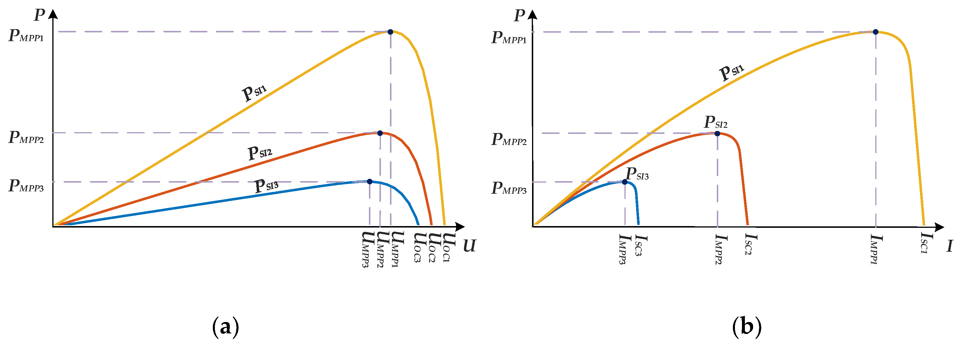
The generation of solar battery power is characterized by a family of power curves for different solar insolation powers: PSI1, PSI2, and PSI3 as functions of voltage U, P = f (U), or current I, P = f (I), as shown in Figure 1a,b. A high level of efficiency is reached when the solar battery is near the maximum power point (MPP) [8], where PMPP = f (UMPP) or PMPP = f (IMPP) with power from the solar panel 1, 2, and 3.
For voltage curves, MPP coordinates UMPP are defined by the open circuit solar battery voltage UOC which is almost constant and belongs to the narrow range UMPP ∈ [0.72·UOC; 0.76·UOC] that slightly depends on solar insolation power PSI. The current MPP co-ordinate IMPP is influenced by the short-circuit current ISC, IMPP ∈ [0.9·ISC; 0.93·ISC]. However, the short-circuit current, ISC, in contrast to the open-circuit voltage, varies widely and is proportional to PSI [9].
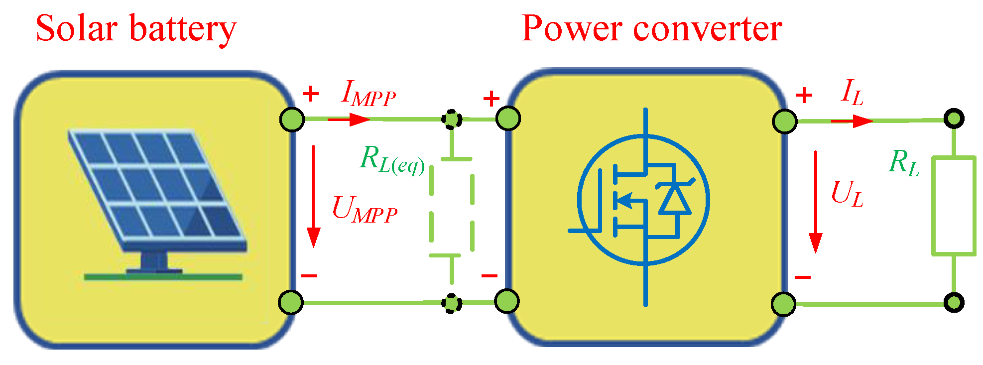
If a load with resistance RL is connected directly to a solar battery, maximum power PMPP is delivered to the load when the equivalent resistance of the solar battery RSB is equal to the load resistance RL in MPT:
in another case, when RSB ≠ RL, power converters as maximum power point trackers (MPPT) are used [10]. The power converter via output voltage (current) UL (IL) regulation tunes equivalent load resistance RL(eq) on the converter primary side according to Equation (2) as shown in Figure 2:
where G is a converter voltage gain.
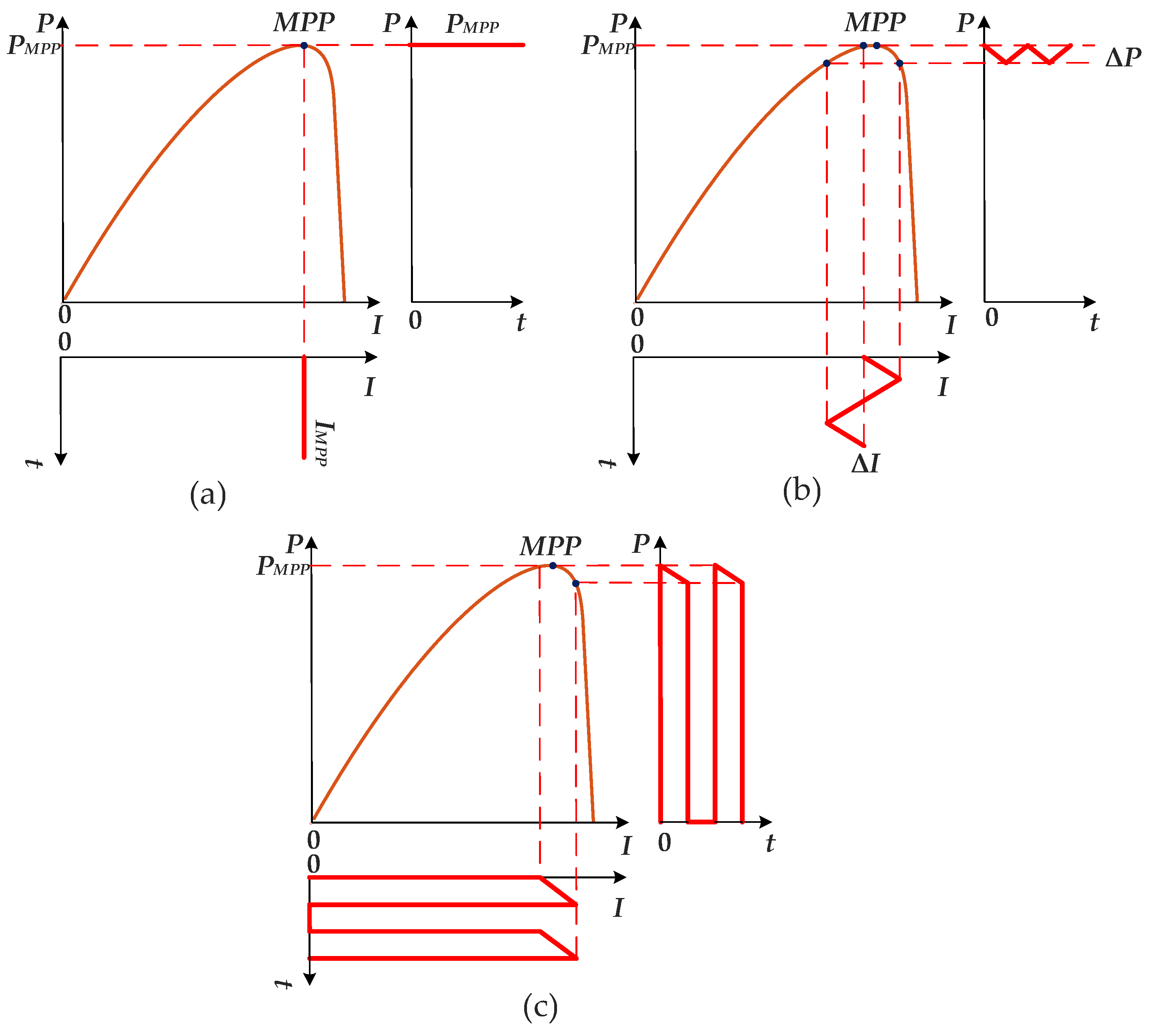
However, even a power converter such as MPPT does not always provide an efficient mode of solar battery operation. As shown in Figure 3a, only constant solar battery current IMPT that fits MPP allows for generating of maximum power for defined solar insolation PSI. If the solar battery current has ripple ΔI, output power pulsation ΔP appears and decreases average power P proportionally to ripple amplitude ΔI as shown in Figure 3b [11]. If the input current is discontinuous, then solar battery energy is used inefficiently as shown in Figure 3c. Therefore, the aforementioned features of the solar batteries impose additional requirements on the power converter as an MPPT, specifically:
- -
- Continuous low ripple input current I;
- -
- High efficiency in a wide power range.
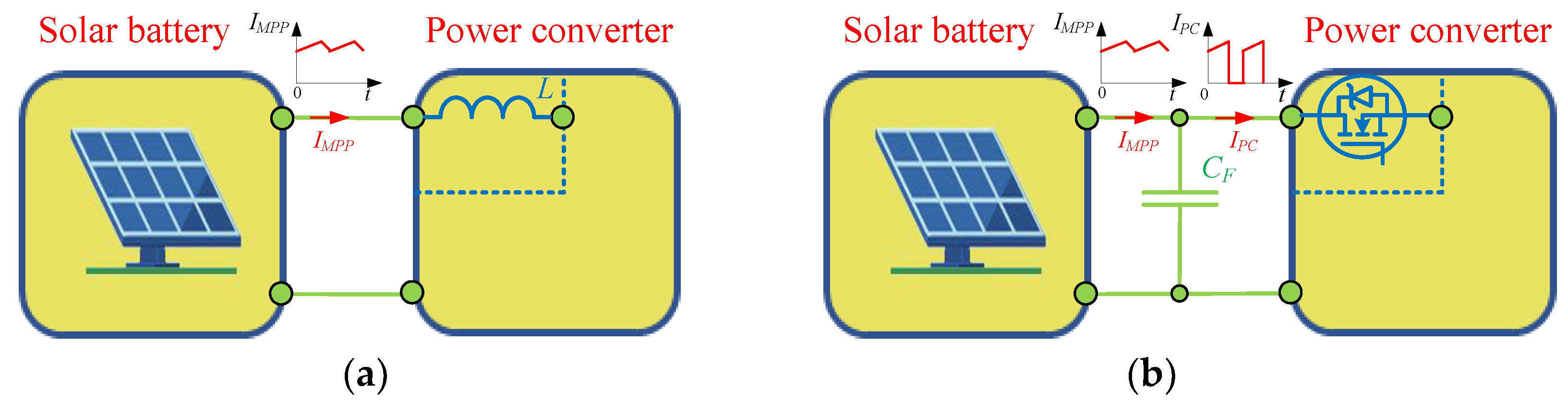
There is an input inductor L in the boost converter [12]. This inductor produces continuous current and can be used directly as an MPPT (Figure 4a). Because it has a series-connected transistor, buck and buck/boost converters have an extra capacitor CF that filters the input current, as shown in Figure 4b.
The equivalent resistance of solar battery, RSB, varies as a function of solar insolation power and is greater than the minimum value RSB(min) attained for maximum insolation:
When solar insolation is zero, RSB tends to infinity. In practice, MPPT works effectively with some range of solar battery resistance RSB ∈ [RSB(min); RSB(max)], where RSB(max) defines the minimum solar insolation power PSB(min) where MPPT may operate [13,14]. Therefore, MPPT has to effectively shift the operating point of the solar battery to MPP in the defined range of resistance RSB. MPPT converters with different voltage gains G are used depending on the relationship between the resistances of a solar battery RSB and the load RL:
- -
- Boost converters (G > 1), if RSB(max) < RL;
- -
- Buck/boost converters (G = G(min)…1…G(max)), if RSB(min) < RL < RSB(max);
- -
- Buck converters (G < 1), if RSB(min) > RL.
The common foregoing conditions of effective PV system design are complemented by the technical aspects of connecting the solar batteries to the power grid or its standalone operation. In Table 1, the topologies of common PV applications and their modifications are listed.
For the efficient design of PV systems, the key task is the correct choice of power converter topology for providing effective energy transfer and conversion. Therefore, it is necessary to pay attention to the following features of power converter design for PV systems:
- The multifunctional purpose of the power converters is:
- -
- -
- Advanced schematic and control algorithms:
- -
- For energy balancing and stable generation, often for AC grid-connected applications, electric batteries with bidirectional chargers are connected [23], as shown in Figure 5c. To make sure that electricity has the right dynamics and quality, you need to use advanced control algorithms with multi-loop and predictive control [24].
- -
- Special issues in converter design:
- -
- For high voltage DC and AC on-grid systems, specialized converters adapted for PV applications are being developed [26];
- -
- Hybrid systems provide parallel operation of several alternative power supplies connected to the power grid and load that in general may be considered a multiport power system [27]. As a result, a reduced-component multiport power system can be made instead of having a lot of separate power converters that do the same thing [28].
Implementation of the aforementioned PV applications is covered by a set of converter topologies with their own advantages and disadvantages. The choice of the most appropriate solution depends on many factors [29]:
- -
- System type (standalone or grid-on, DC or AC);
- -
- Voltage and power level (low, middle, or high);
- -
- The relationship between the voltage of the solar battery and the grid;
- -
- Additional requirements on power factor value and power stability.
For instance, an MPPT unit may be effectively realized with either a DC–AC converter or a two-stage power system with DC–DC and DC–AC converter; a storage system may be installed on the DC–DC side of the PV system or directly on the DC or AC system; a PV system may be connected to the grid with one or few high-power converters, or realized as a distributed system with a set of low or middle power converters, etc.
This paper looks at different topologies that could be used to solve the discussed problems It also tries to show the good and bad points of the solutions based on proper generalization parameters that allow comparing their effectiveness.
In general, power converter comparative analysis is performed based on their complexity, i.e., number of inductors, capacitors, and semiconductor components [30], also taking in to account voltage gain characteristics, control strategy, efficiency, etc. However, the most fruitful results are obtained by comparing converters designed to solve a particular problem that put forward a number of specific requirements to the power converter. For instance, for designing a dynamic voltage restorer [31], these parameters are high dynamics, wide reactive and active power regulation range, and easy energy storage integration, whereas for AC/DC Microgrids [32] parameters are the value of output impedance, type of power flow control, voltage modulation strategy, and voltage and frequency regulation. For solar applications, the main requirement, as mentioned before, is high efficiency in a wide power range and, as for industrial solutions, low cost per unit of power.
As a numerical criteria of the converter cost per unit of output power, Pout may be measured by the cost factor kC which is inverse to the transistor utilization factor kU [33]:
where S is total switch stress and:
where N is the switch number of the power converter, and Ukmax and Ikmax are the maximum voltage and current stress of the switch k, respectively. Normalized power loss P* [34] of the switch can be used to estimate power converter efficiency.
Detailed and comprehensive comparative PV converter analysis in space of cost factor and normalized power loss is carried out in the paper in such a sequence.
Section 2 discloses a methodology of deriving cost factor and normalized power loss for DC–DC and DC–AC converters with hard and soft-switching transistor commutation.
In Section 3, Section 4, Section 5 and Section 6, classification, cost, and efficiency comparisons of power converters for AC grid, energy storage, high voltage gain, and hybrid PV applications are given.
Discussion (Section 7) deals with the overall analysis of PV application design and recommendations.
2. Materials and Methods
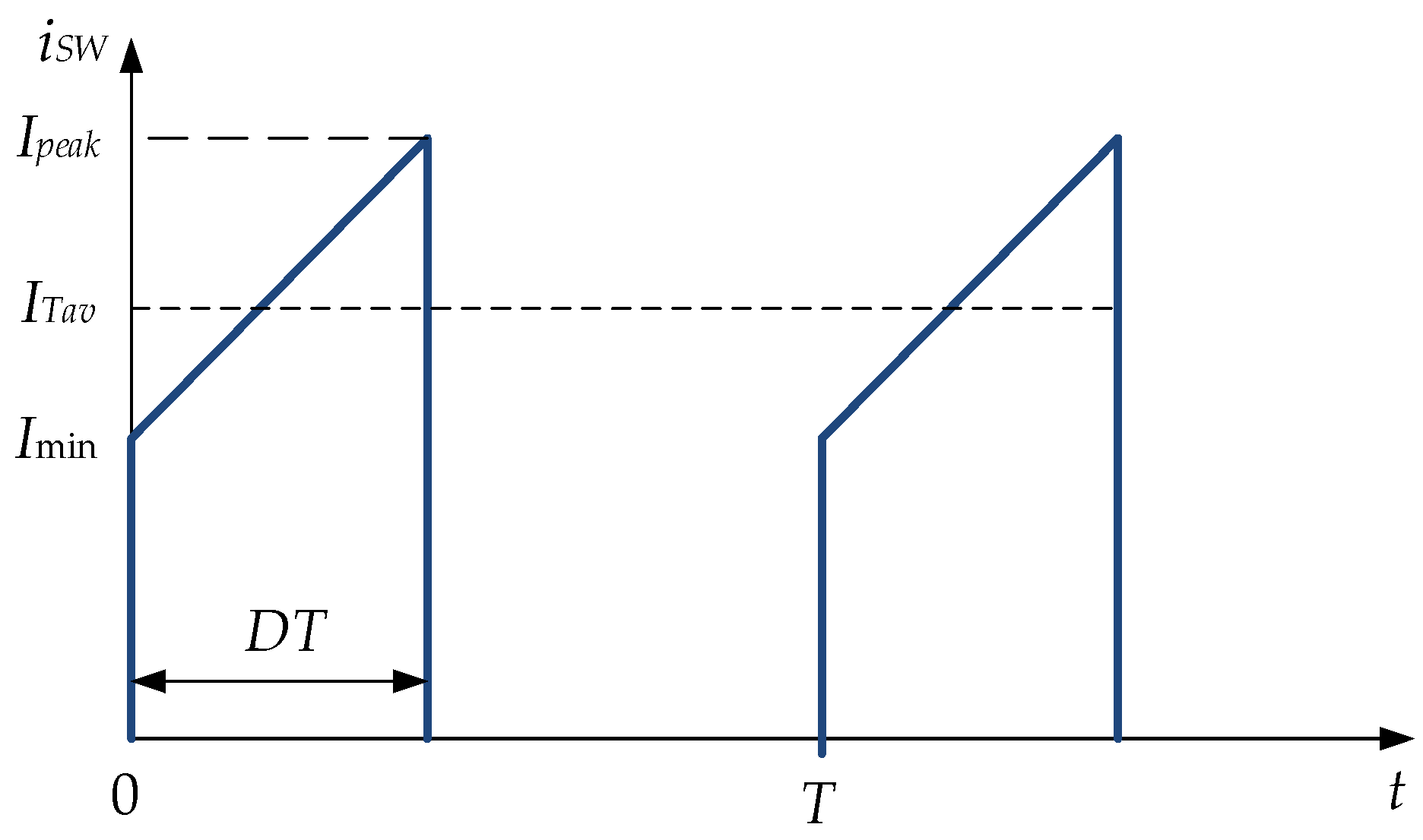
According to standards for solar batteries and inverters [35,36,37,38], the maximum operating voltage of PV equipment currently does not exceed Umax = 1500 V. In this case, the converter is connected to 1–3 solar battery strings with a short-circuit current of 10 A per string. Application design with such operating voltage and current, as usual, is performed based on Si IGBT or SiC MOSFET transistors [39]. Due to less static and dynamic power loss, and a permanent price reduction in SiC transistors, Cree C2M0080170P is used for loss calculation [40]. Static loss of the transistor Pst* with a constant current IDC that provides output power Pout at voltage Umax is normalized and defined as PTst* = 1 p.u. It is well known that the resistance RDS(on) of SiC and MOSFET transistors quadratically increases with voltage. Additionally, power loss depends on transistor current shape, which in a general case for DC-DC converters is shown in Figure 6. There are shown peak and minimum transistor values, Ipeak and Imin, correspondingly. Average value of transistor ITav on interval DT is calculated as ITav = (Ipeak + Imin)/2.
Thus, the RMS value of ISW(RMS) compared with IDC is calculated as follows:
where kTst is the factor that depends on converter topology.
If there is no pulsation in the current, Ipeak = Imin = ITav, and the RMS value is calculated using the average transistor current value ITav on the interval DT:
Therefore, k switch power loss PTst(k)ht* for hard-switching converters with overvoltage Ukmax is defined as:
Whereas in resonant converters with sine wave current shape, the power loss PTst(k)s* is multiplied by shape factor ksh = π2/8 [41]:
Due to the nearly rectangular shape of the current in soft-switching converters, the static power loss is considered the same as for constant current PTst*.
The dynamic power loss PTd∗ for hard-switching mode is calculated using a comparison of transistor static and dynamic losses at maximum power IDC = 30 A, Umax = 1500 V at switching frequency fsw = 40 kHz, PTd∗ = 0.5 p.u. The dynamic loss PT(k) d* for defined transistor current ITk and voltage UTk is:
It is considered that in resonant and soft-switching converters, dynamical loss is absent.
A diode’s static power loss PDst* is calculated based on Cree C5D25170H [42] and expressed in units of PTst*, PDst* = 0.8 p.u for constant current IDC. If the diode’s forward VD is assumed to be constant and proportional to reverse voltage Ukmax, its static loss for the hard-switching converter is calculated as follows:
where kDst(k) is the relationship between the average value of the diode current IDk on the interval (1 − D) to current IDC:
whereas in the case of soft-switching:
Dynamic loss of the diode for current IDC is PDd∗ = 1 p.u. For defined diode current IDk and voltage UDk, dynamic loss PD(k)d* is calculated similarly to the Formula (9):
The final values of static and dynamic power losses for DC–DC converters are given in Table 2.
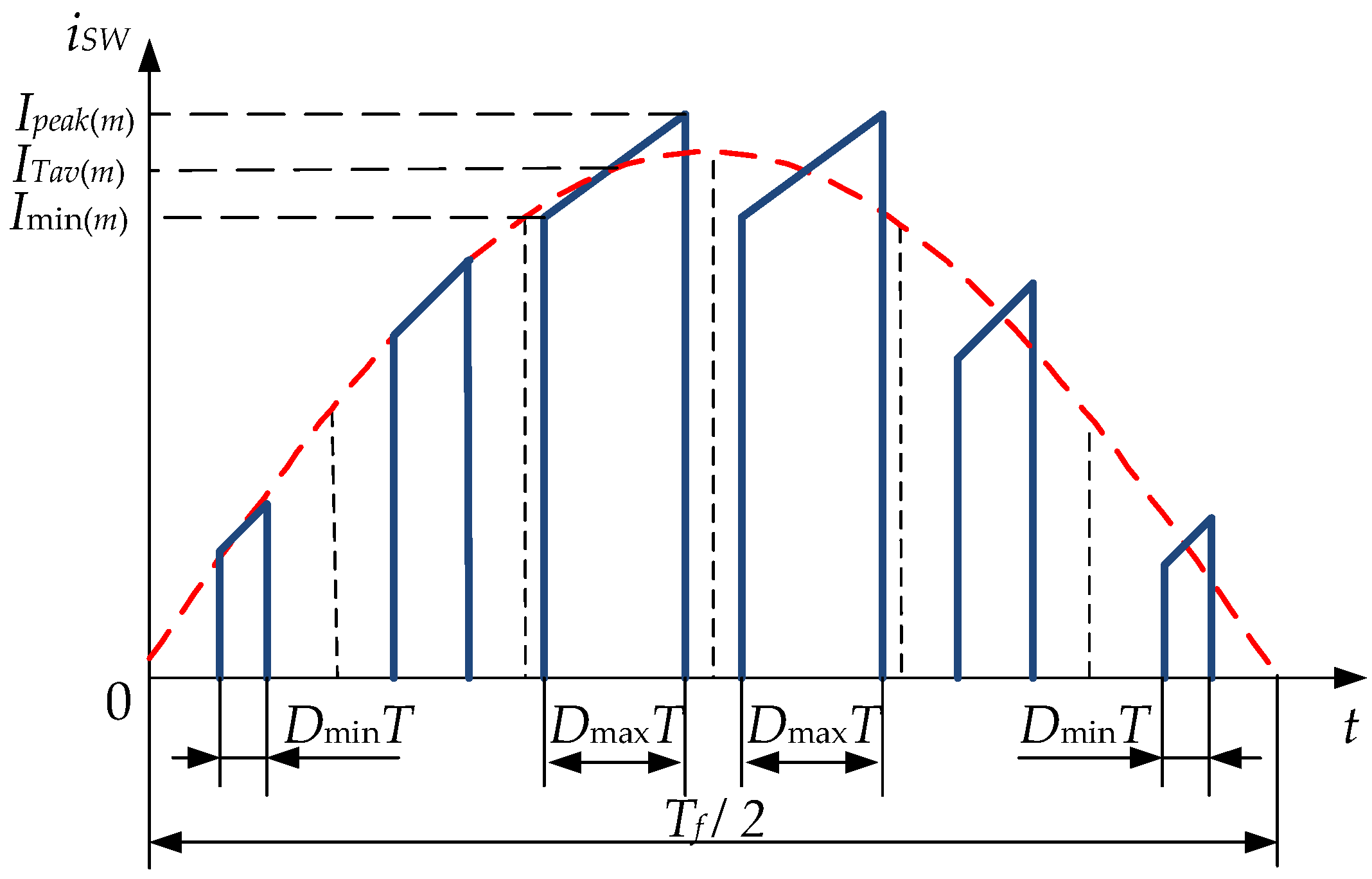
For DC–AC and AC–DC converter output, AC side voltage and current are sinusoidal; therefore, diodes and transistor current, as well as power loss, depend on grid voltage phase φ = 2π·t/Tf, where Tf is the fundamental period of the grid voltage that is shown in Figure 7.
The amplitude peak current values Ipeak(m), ITav(m), and Imin(m) are used to calculate the AC shaped current cost factor kc, whereas the power loss Pcon(AC)∗ analysis is performed based on the integration of instantaneous power loss Pcon(AC)∗ from Table 2, where duty cycle D is a function of power grid phase φ, D [0; Dmax], and normalized with current inorm:
where inorm = π·sin(φ)/2 has a half-period average value of unity:
Thus, equations have been derived that can be used to calculate the total converter power loss Pcon∗ and the cost factor kc for both AC and DC applications. These numbers are used to compare different PV applications with different converters for each type of PV.
3. AC Grid on PV Applications
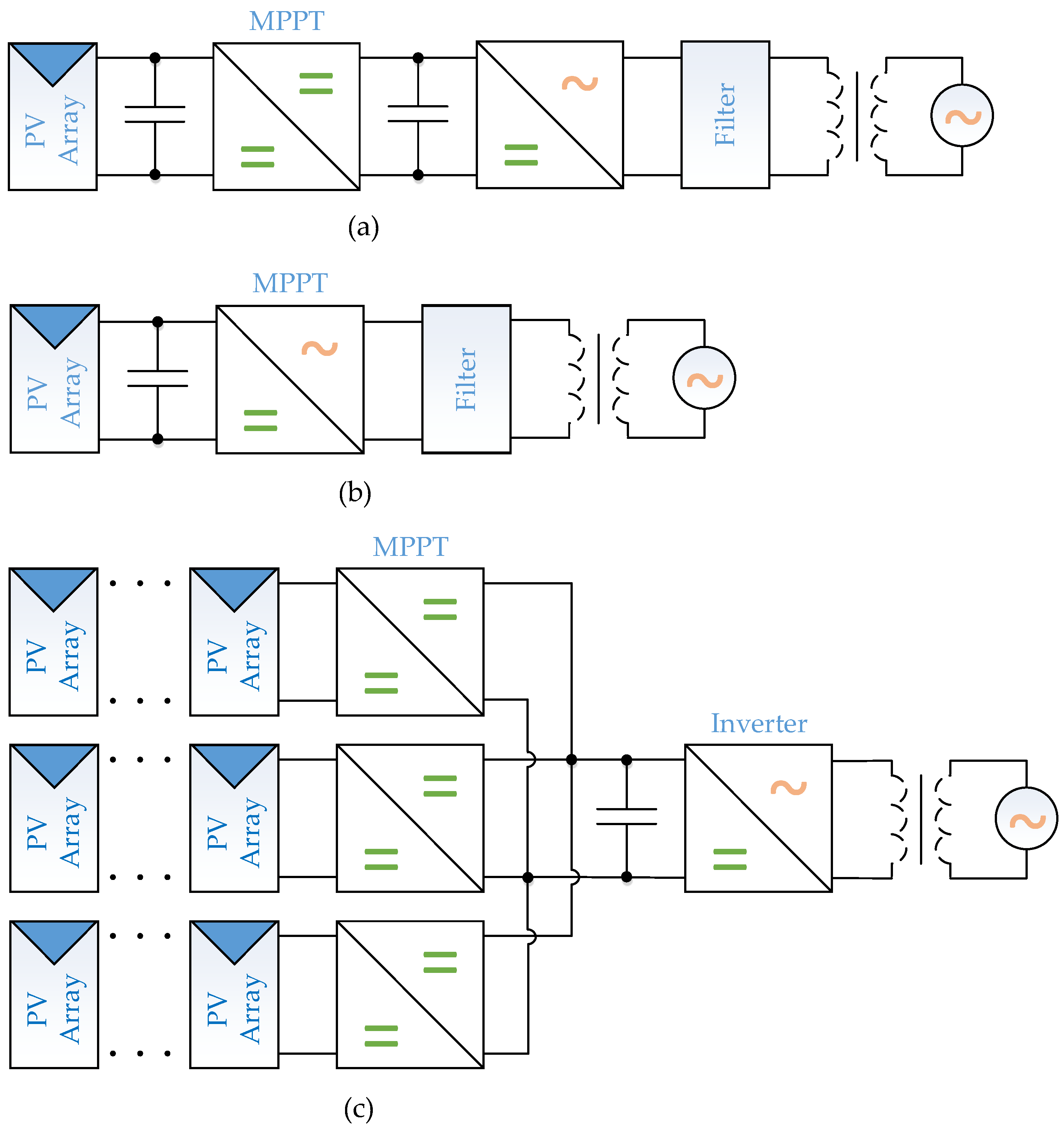
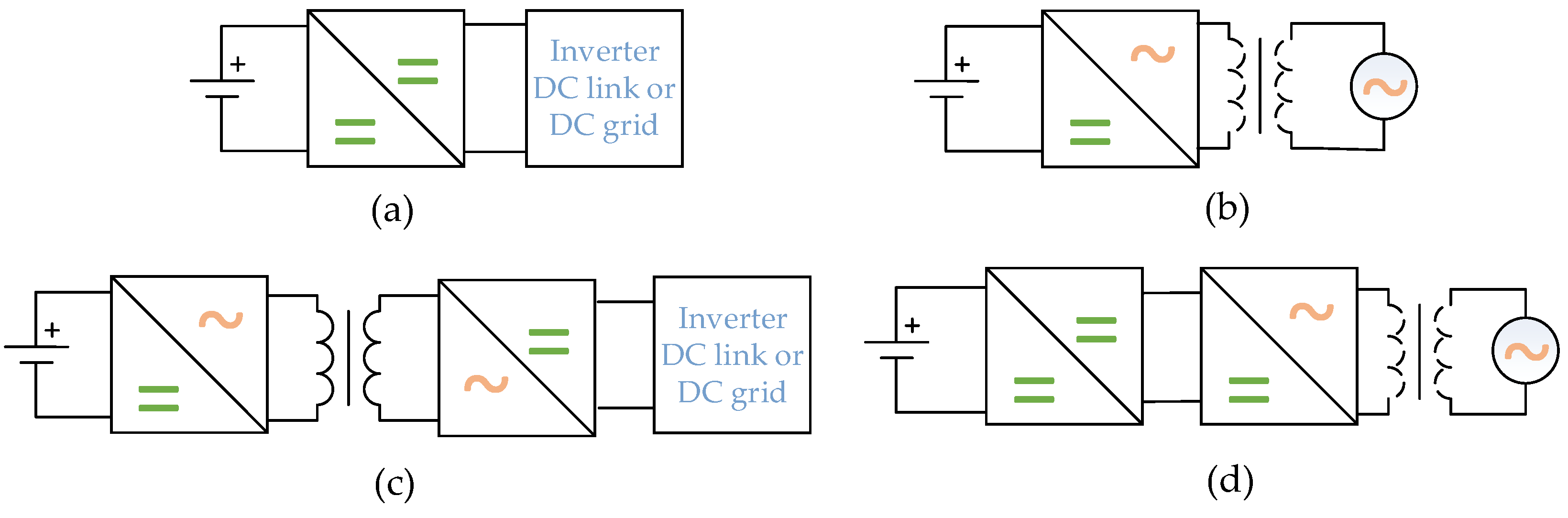
AC grid-connected renewable applications aim to deliver the maximum possible energy to the grid as efficiently as possible. This will be accomplished using single-stage or two-stage systems. The single-stage application is an inverter that simultaneously performs the functions of MPPT, boosting, and voltage conversion from DC to AC [43]. In the two-stage converter, these functions are split between DC–DC and DC–AC inverters [44]. Depending on the safety conditions or voltage gain requirements, applications may be equipped with transformers or be transformerless. Typical structures of on-grid applications are shown in Figure 8.
In terms of improving efficiency and reducing the cost of the system, single-stage systems have clear advantages over two-stage. Nevertheless, two-stage systems are actively used due to simple system control and the opportunity to connect energy storage to DC-link or design multi-string PV systems [45]. In two-stage systems, any non-isolated DC–DC converter can be used as MPPT [12], but mostly boost, buck, and buck-boost converters are used due to less transistor stress [46]. For reducing power loss, soft-switching [47] or interleaved converters [48,49] are used.
As usual, single-phase or three-phase bridge topologies are implemented for the design of DC–AC converters in single and two-stage topologies [50]. Soft-switching commutation and reduced power loss are possible with advanced control methods [51,52].
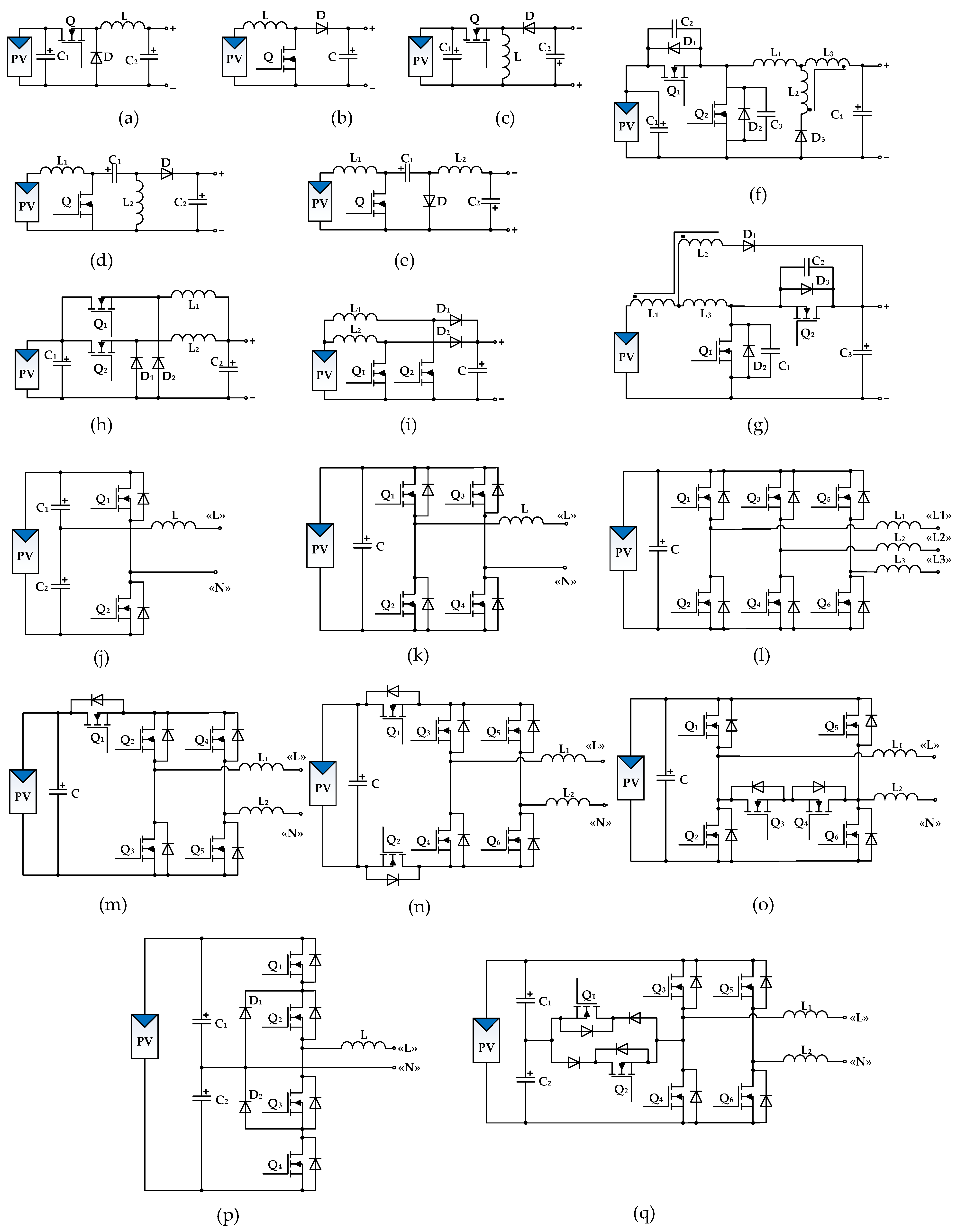
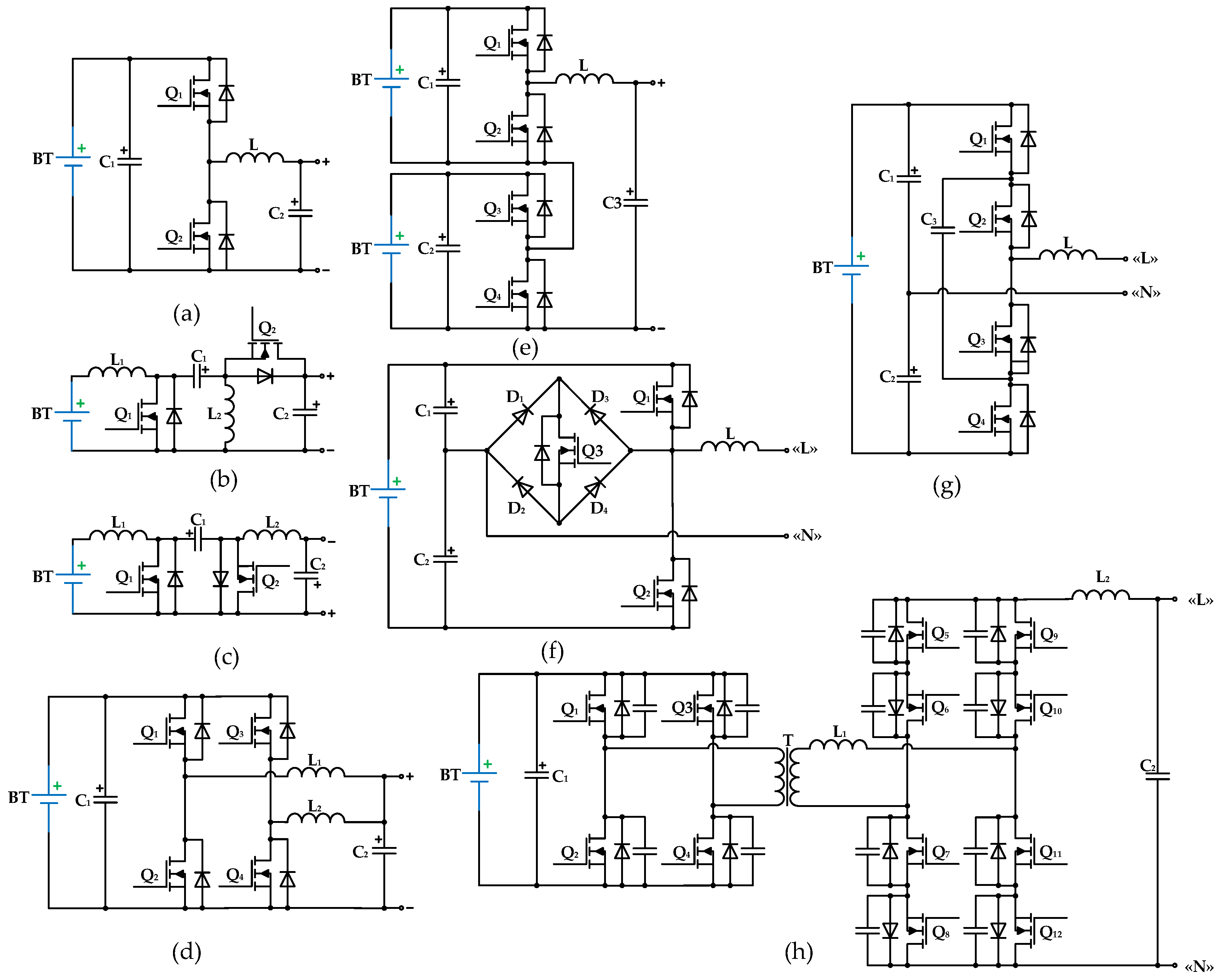
Non-isolated one-phase inverters with common full or half-bridge topology suffer from leakage current that flows between AC grid ground and PV through parasitic capacitors [53] and brings about safety and interference issues [54]. Additional transistors implemented in H5, H6, HERIC, and hybrid-bridge topologies [55] cut off the leakage current path and eliminate it. For transistor overvoltage limitation, multilevel inverters, for instance, 3L-NPC [56] and 3L-SC [57], are used. The aforementioned DC–AC PV application schematics are illustrated in Figure 9 and listed in Table 3 for one stage DC–DC and DC–AC converters, respectively, with cost factor kC and normalized power loss of the converter Pcon*.
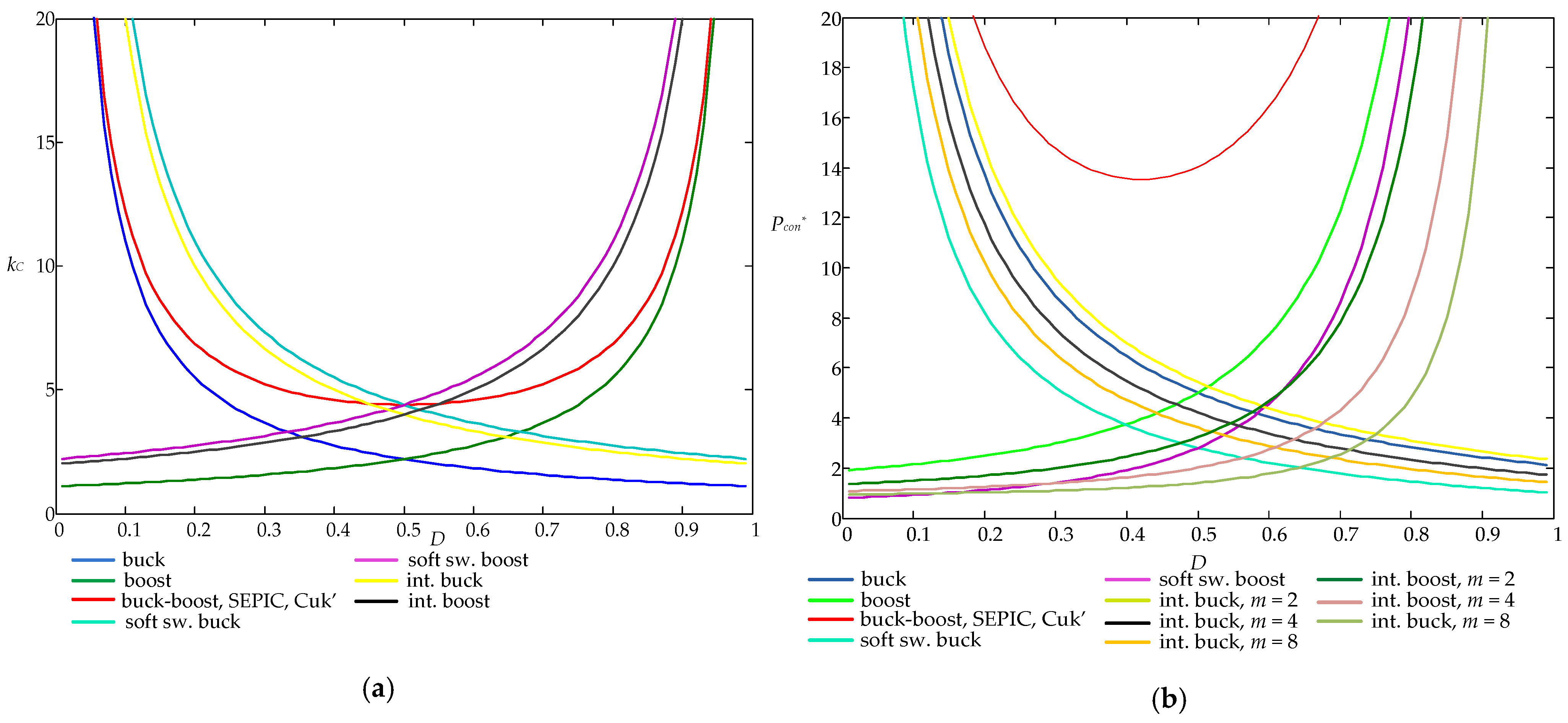
Because low current ripple ΔI is a key requirement of the grid on applications for sufficient power factor, the majority of converters use Imin = 0.9 ITav(m), Ipeak = 1.1 ITav. However, interleaved converters operate in boundary mode, when Imin = 0 and Ipeak = 2 ITav. Based on the aforementioned assumptions, the cost factor kC and normalized power loss Pcon* of DC–DC converters are shown in Figure 10a,b, respectively. The same curves for DC–AC converters are shown in Figure 11a,b.
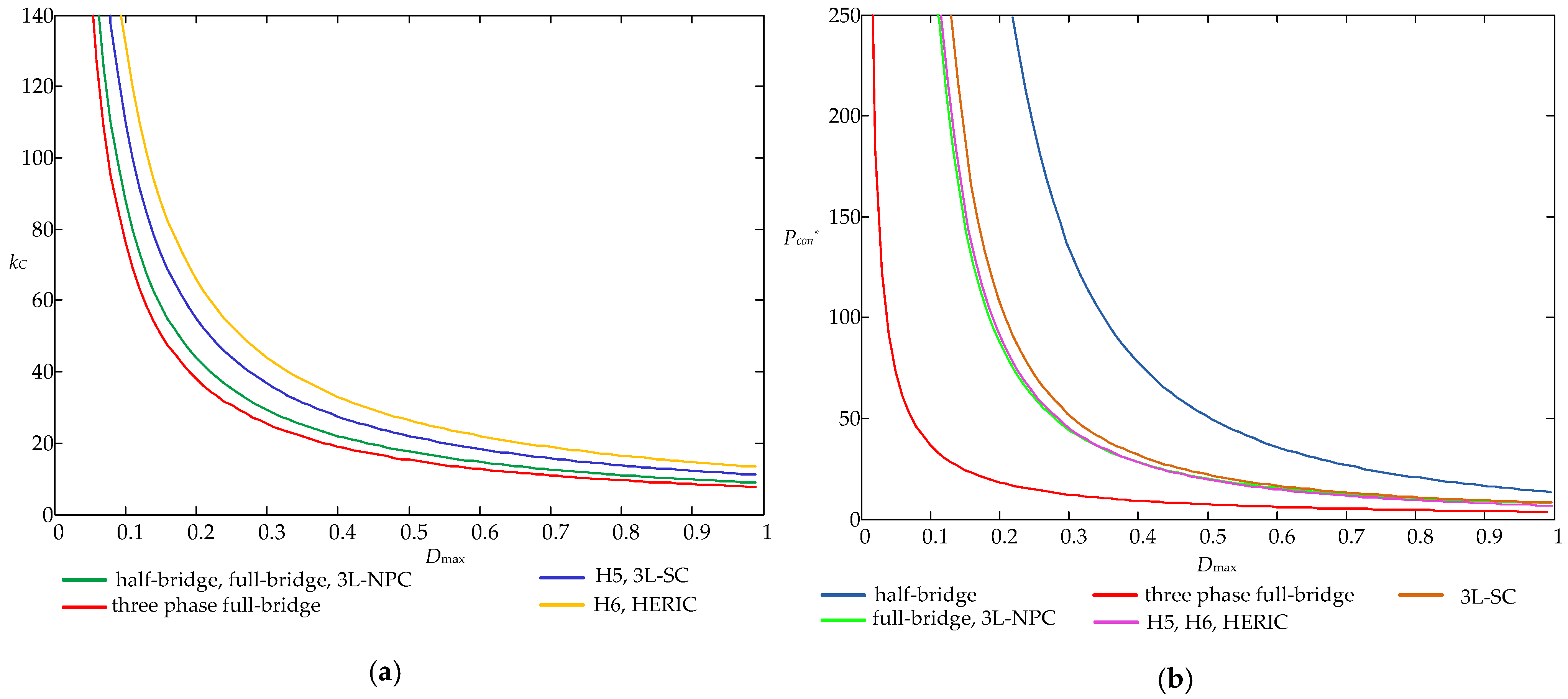
Because of a larger number of transistors, DC–AC converters are weaker in terms of parameter values kC and Pcon* than their DC–DC counterparts. Among DC–DC converters, the most effective solutions are based on buck and boost converters. Whereas buck-boost solutions (buck-boost, SEPIC, Cuk’ converters) increase costs and losses. interleaved converters allow for reduced losses at the expense of an increase in price and dimensions.
Among DC–AC converters, three-phase is the most efficient converter because of the minimum number of transistors per phase. For single-phase applications, full-bridge, H5, H6, and HERIC converters have very similar kC and Pcon* values.
Two-stage DC–AC applications may be used for PV applications in the following cases:
- -
- Boosting DC voltage;
- -
- Decreasing kC and Pcon* to allow for a wider range of input/output voltage operations;
- -
- Inconsistency of power grid and solar battery voltages.
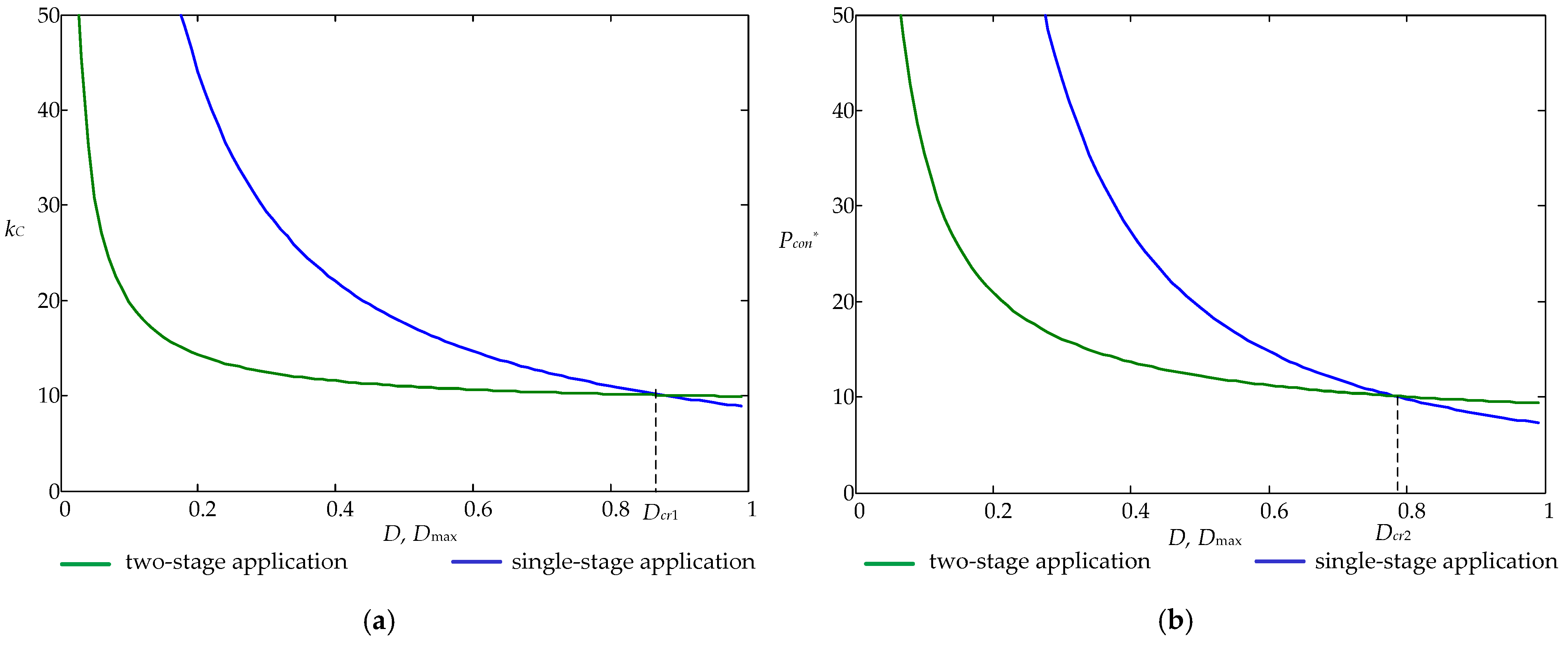
In a two-stage system, voltage regulation is performed at the DC–DC stage, whereas the DC–AC stage operates with the maximum duty cycle, Dmax → 1, that provides minimum power loss. For instance, Figure 12a compares the cost factor kC of single-stage applications based on a full-bridge converter and a two-stage application designed on buck and full-bridge converters. Figure 12b compares power loss for the same configurations with Dmax = 1 for the DC–AC converter of the two-stage system. Formulas for the considered cases are shown in Table 4.
Figure 12 shows that for Dmax < Dcr1 = 0.87 and Dmax < Dcr2 = 0.78, the two-stage system has a lower cost factor kC and a lower power loss Pcon* than the one-stage system. This means that the two-stage system is more efficient than the one-stage system.
Aside from energy-delivery, common DC–AC applications have additional functionality [58]:
- -
- Voltage conversion and power grid synchronization;
- -
- Disconnection and anti-islanding protection when power grid fault appears; Correction of the power factor of the input current.
The rapid evolution of on-grid PV applications with unstable generation complicates the grid’s stable operation. Due to the common DC–AC application’s disconnection from the power grid fault, the grid operation only worsened and became unbalanced. As a result, using converters with advanced functions that remain connected to the grid during faults and attempt to maintain a stable operation not only mitigates the impact of renewable energy instability, but also creates additional opportunities for power grid control and improves reliability [59].
The list of additional converter functions that improve power grid operation and converter control approaches, as well as topologies that may perform them, are given in Table 5.
As usual, the inverter’s advanced functions are realized with basic inverter topologies with improved control strategies and require no extra elements except for sensors.
4. Energy Storage Applications
An energy storage system is an integral part of renewable power supply systems. The main purpose of the storage system is to provide a powerful balancing of unstable renewable sources that operate at MPP and variable load. Typical converter topologies of energy storage applications are shown in Figure 13.
Single-stage DC–DC and DC–AC topologies in Figure 13a and 13b respectively have simple structures and functionality. DC–DC converters for built-in energy storage connect to two-stage on-grid PV inverters or DC power grids, whereas DC-AC topologies are connected directly to the AC power grid. Figure 13c,d are used for energy storage isolation in DC power grids or AC grids and provide much more functionality, i.e., multi-mode charging, a wide range of battery charging voltages and currents, advanced control, improved performance, and energy quality control.
With increasing renewable energy penetration, energy storage systems are becoming a necessary element to maintain stable grid operation. In particular, in the concepts of intelligent transmission and control of distributed systems FACTS [66], Smart Grid [67], and Vehicle to Grid (V2G) [68], energy storage is considered as a system-forming unit or unit that strongly improves the system operation, specifically:
- -
- Load shifting occurs when renewable energy mostly charges the energy storage during the day, and the energy storage is discharged in the late hours of peak power demand [69];
- -
- Shutdown protection in smart distributed power grids that allows supplying end-users when loss of power arises [70];
- -
- Energy quality control (voltage, frequency, reactive power compensation, high harmonic reduction) [71].
Therefore, distributed systems usually use a single common storage system which improves the functioning of the entire system.
Because of the unstable generation of renewable sources, energy storage is permanently switched between charge and discharge modes with the unstable current. Therefore, energy storage control is much more intelligent than for a common charging device [72,73].
For DC–DC in stage energy storage applications, some of the converters discussed in the section about grid applications with modified control laws, such as full or half-bridge [74] and 3L-NPC [75] converters, require minor modifications and an increase in the number of transistors, for instance, SEPIC, Cuk’ [76], or cascaded [77] and interleaved [78] half-bridge converters.
Electric isolation in DC applications is provided with a high-frequency transformer intermediate AC link. An AC link may be organized with dual full- or half-bridge converters and their soft-switching modifications [79,80,81].
Multi-level [82,83] or high-frequency link AC–AC converters [84] are used for single-stage AC applications, whereas full- and half-bridge converter modifications [85,86] are used for two-stage solutions.
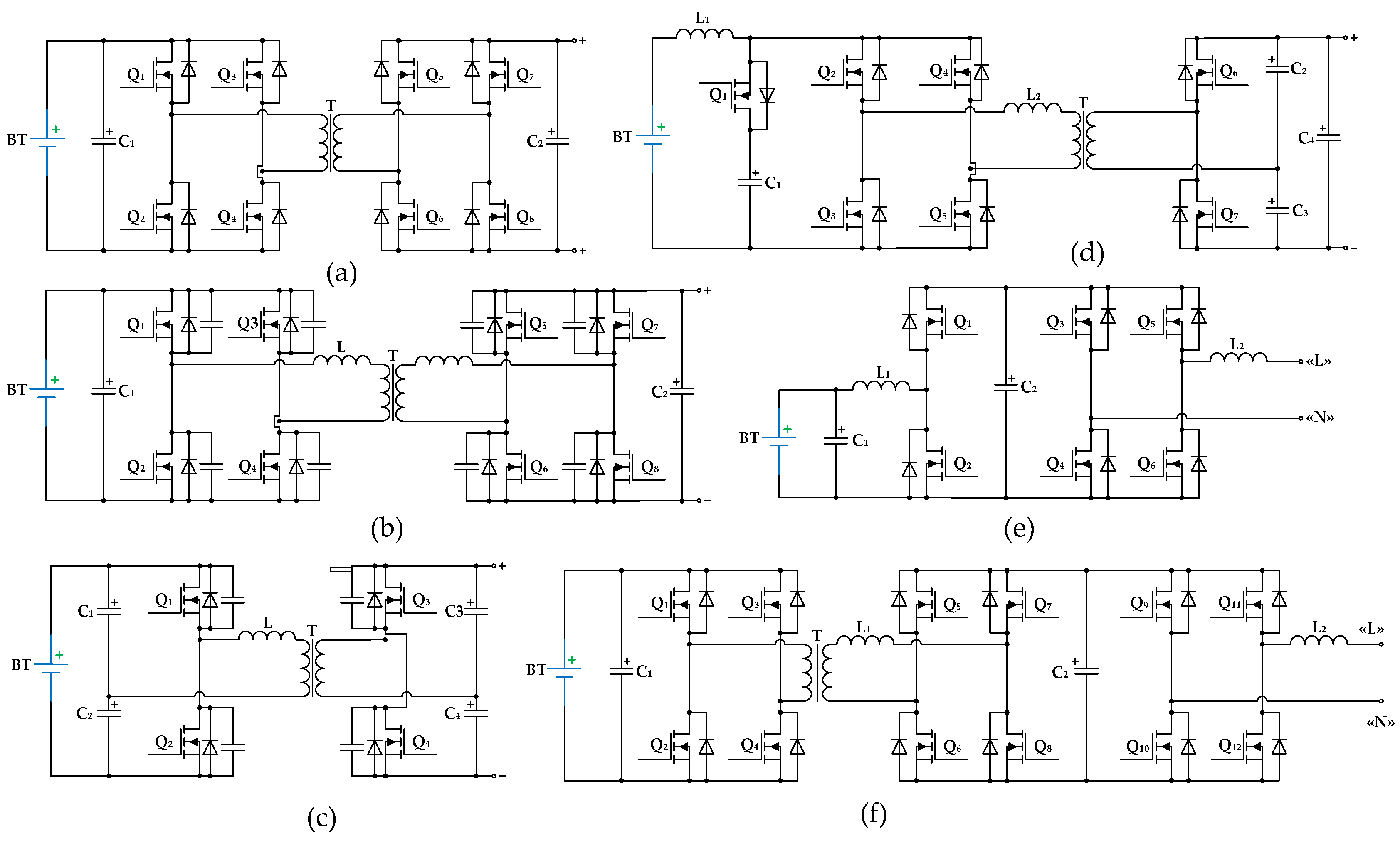
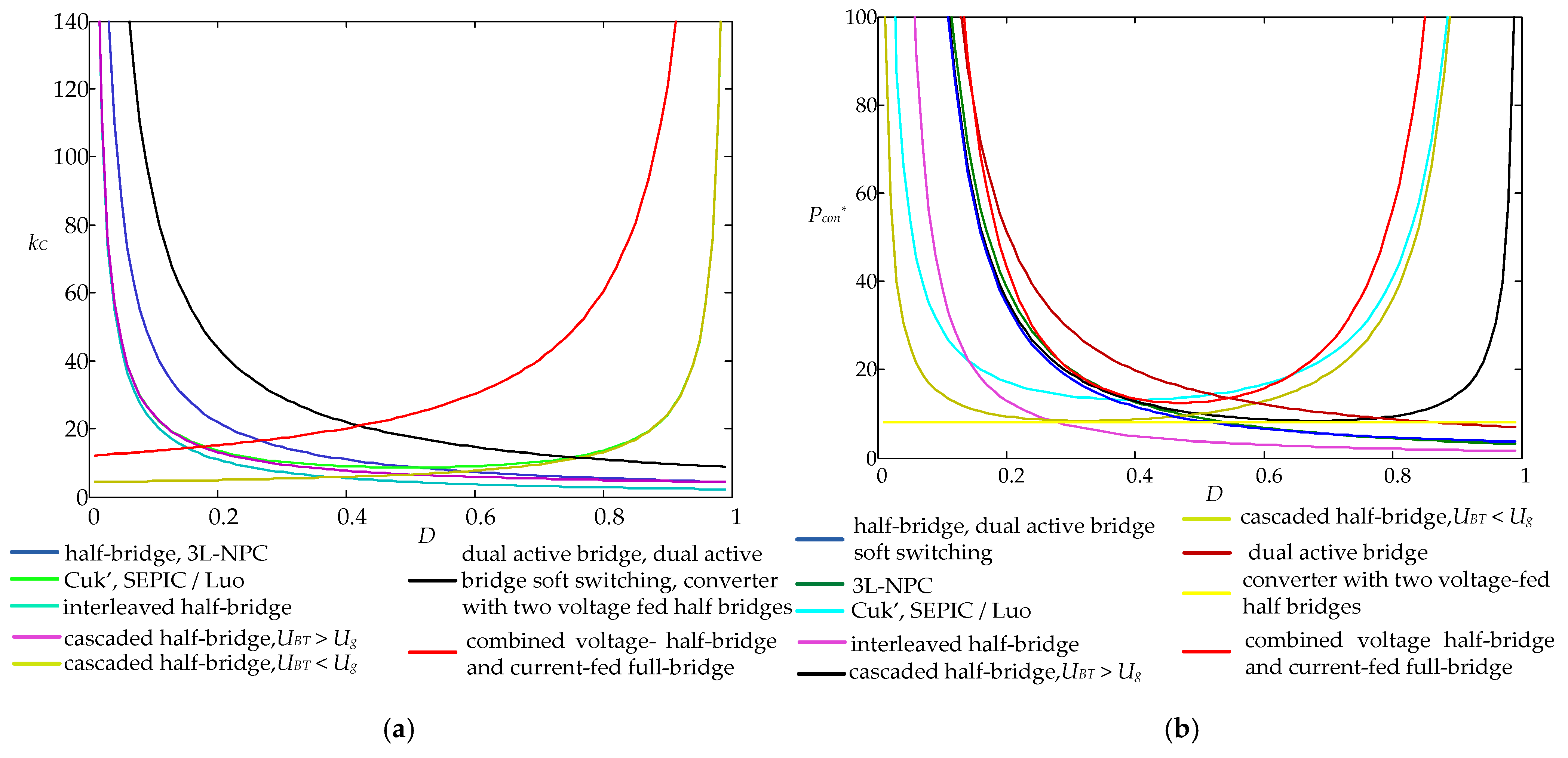
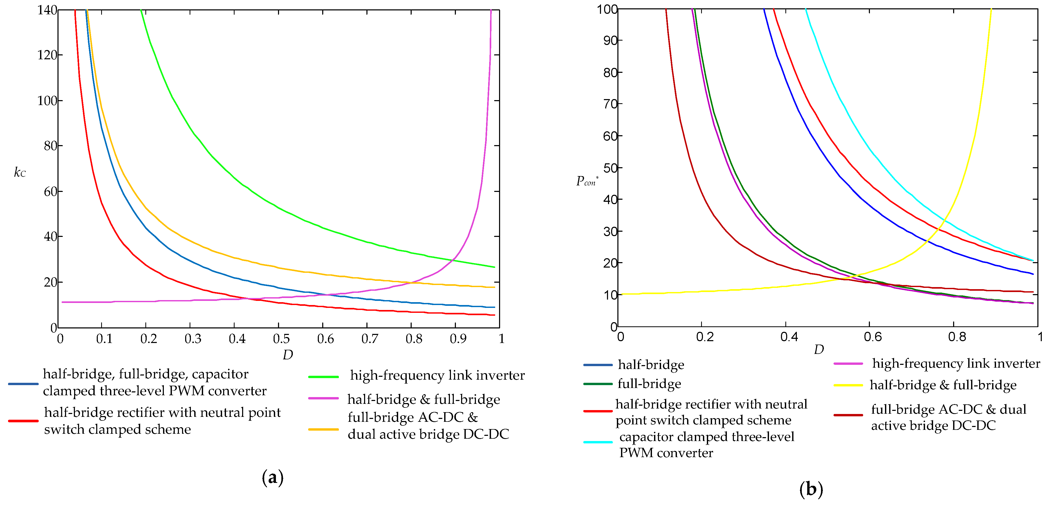
Figure 14 depicts converters for single-stage storage applications, and Table 6 compares them based on the parameters kC and Pcon*, whereas two-stage solutions are shown in Figure 15 and Table 7, respectively.
As usual, the voltage gains of the power converters used in energy storage applications are different. This means that the duty cycle values and power loss values (Pcon*) are different depending on which way the power converters are used. For instance, a full-bridge converter, shown in Figure 9k, operates as a boost converter with duty cycle D1 when energy is stored and as a buck converter with duty cycle D2 when delivering energy to the power grid. The relationship between the parameters D1 and D2 is equal to:
Thus, power loss Pcon* estimation depends on the direction of energy transfer. As long as the same amount of energy is sent in both directions, the power loss weight formula is used with weight factor w = 0.5:
where Pcon1* is the power loss value for operation in energy storage mode with duty cycle D1, and Pcon2* is the power loss value for operation in delivering energy to the power grid with duty cycle D2.
In two-stage DC–AC energy storage applications, the first and second stages operate independently, so their operation is defined by four duty cycles, i.e., D1, D2 for the first stage and D3, D4 for the second stage. However, DC–DC two-stage applications always contain AC links that are used for electric isolation and soft-switching. Therefore, one of the stages always works in passive mode as a rectifier with the same duty cycle.
Derived results in Figure 16 and Figure 17 make it clear that more effective applications are designed with basic half- and full-bridge topologies with improved dynamic loss. For DC–DC applications, there are cascaded and interleaved half-bridge topologies and 3L-NPC converters, whereas effective DC–AC applications are based on full-bridge, and full-bridge and half-bridge topologies.
5. High Voltage Gain Converters
Solar panels have relatively low voltage and current and are usually combined with batteries in parallel and series connections. The variation of power in solar radiation and in the parameters of the panels in the battery leads to a decrease in overall efficiency [87] and may cause system instability due to partial shadowing effects [88]. For mitigation of the aforegoing drawbacks, high voltage gain converters are used. The common voltage boosting method, with a high-frequency transformer and high turns ratio n, increases component stress on the secondary size and causes leakage inductance voltage spikes, thus non-isolated converters are often used in practice. A high gain value G for the conventional boost converter is achieved to the detriment of power loss with operation in modes with a close to unity duty cycle [89]. A cascading technique involves a series connection of several converters and expands the total voltage gain value G several times [90]. It increases the cost and complicates the converter design and control. For efficiency improvement the interleaving technique is used [91].
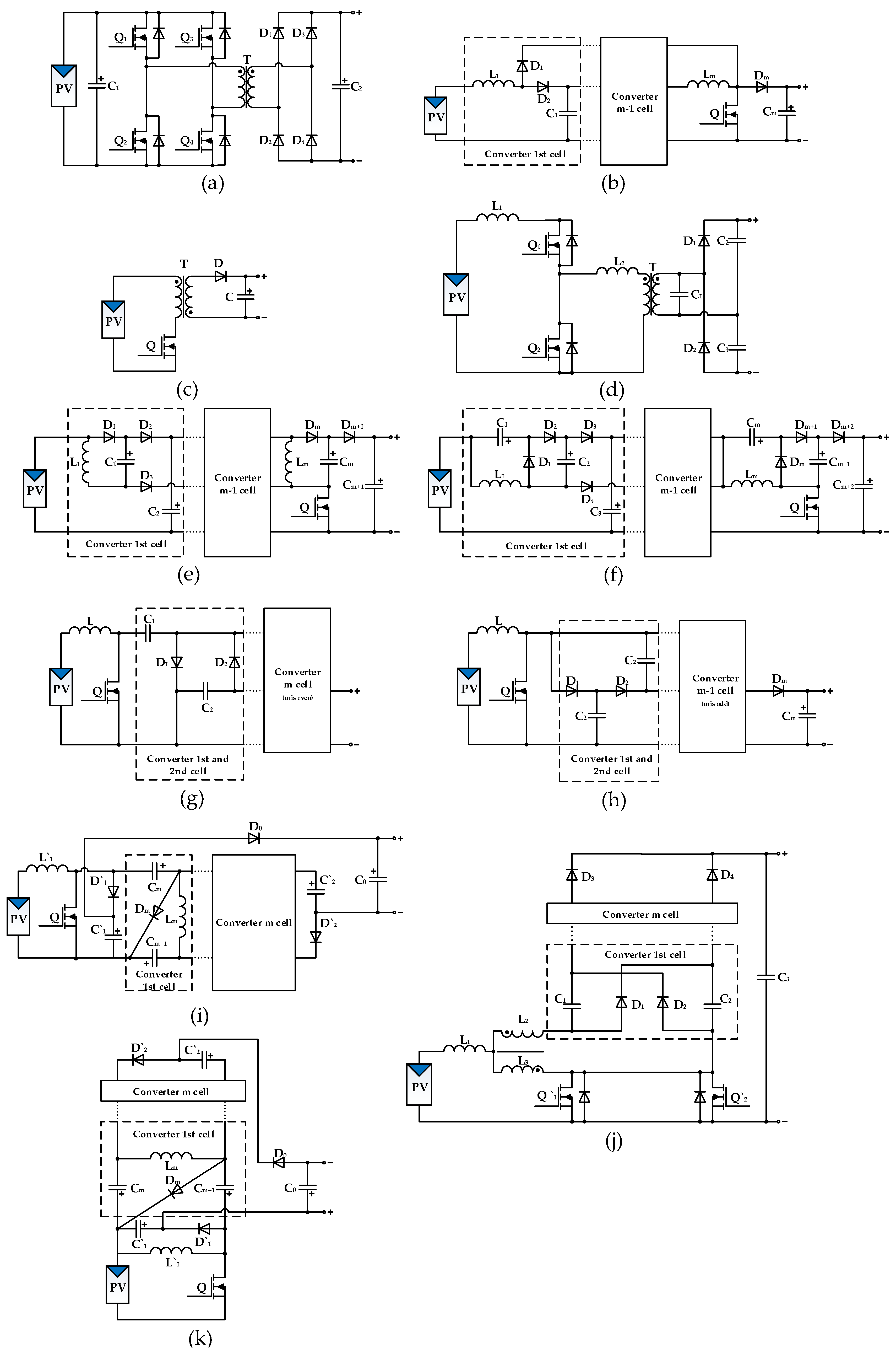
Other DC–DC converters, such as SEPIC and Flyback, can provide galvanic isolation via additional winding on the inductor core. These converters are used for high voltage gain but require additional snubber circuits to mitigate issues caused by leakage inductance [92] and usually suffer from increased transistor overvoltage with factors of 1.5–2.0. Passive dissipative RCD snubbers are commonly used [93], but for high-efficiency solutions more sophisticated active [94,95] or passive [96,97] regenerative snubbers deliver energy leakage inductance on the load or primary energy source. In addition, an isolated solution with leakage inductance allows the implementation of transistor soft-switching as well as voltage doubling, for instance, in an LC parallel current source converter with a voltage doubler [98]. The idea of capacitor voltage doubling is used for a set of multi-cell flying capacitor converters: super lift voltage converter [99], modified voltage lift converter [100], Cockcroft Walton multiplier based boost converter [101], Dickson multiplier based boost converter [101], boost derived MIESC SC-cell converter [102], and buck-boost derived MIESC SC-cell converter [102]. Capacitor voltage doubling is also realized in converters based on a three-state switching cell (3SSC) that is a combination of two switching PWM cells (2SSC) [103]. Such converters have reduced the size, weight, and volume of magnetics and reduced the current stress of switches.
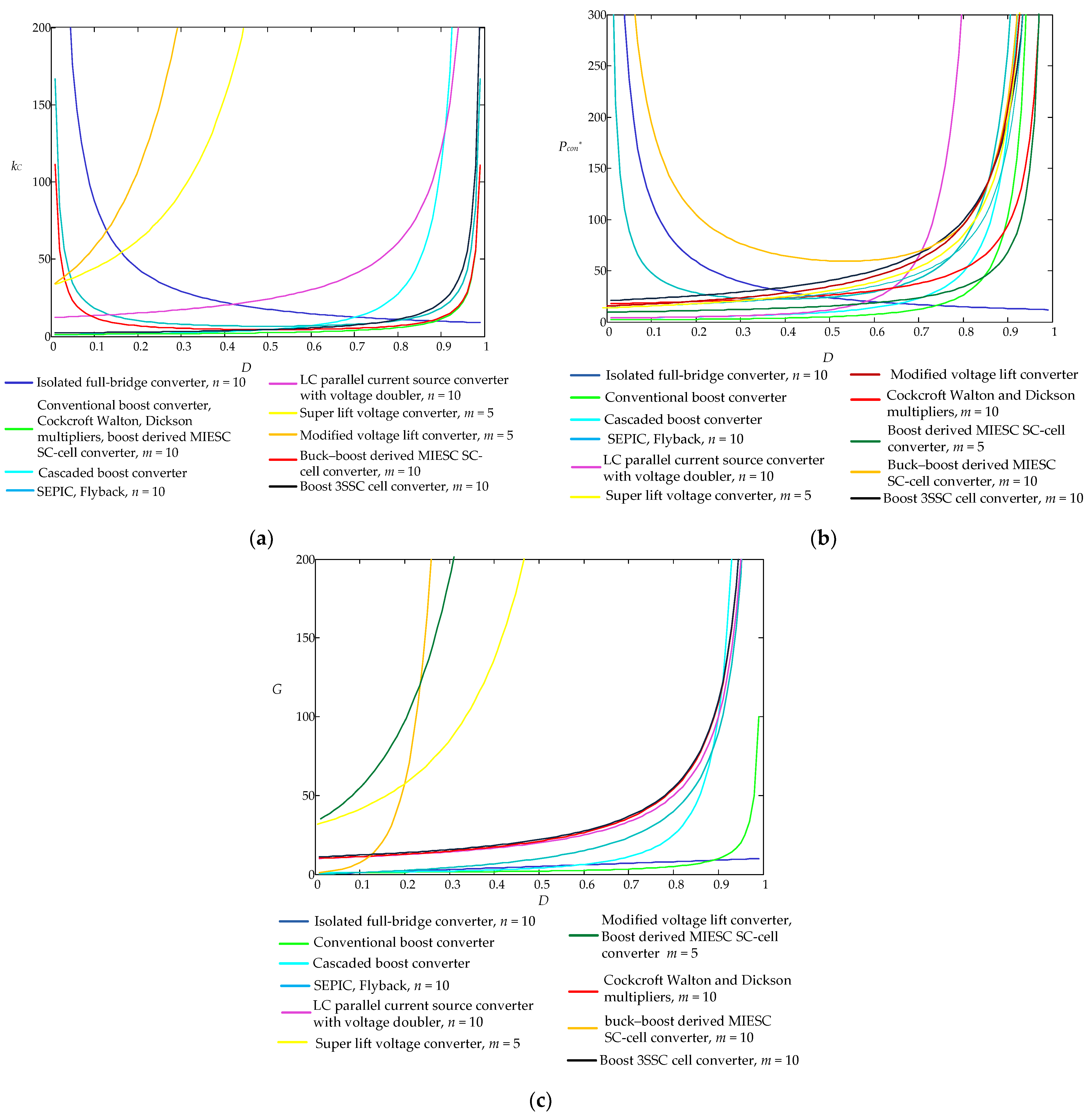
Figure 18 shows the reviewed topologies of high gain converters, whereas Table 8 analyzes the main features of high gain converters, i.e., voltage gain G, switch voltage stress, and basic parameters kC and Pcon*.
As shown in Figure 19a, an essential problem for high gain applications is significant transistor overvoltage. As a result, power converters with lower transistor stress recalculated on the gain unit, such as Cockcroft–Walton and Dickson multiplier-based boost converters, boost derived MIESC SC-cell converters, and boost 3SSC cell converters, are more appealing for high voltage application design.
6. Hybrid PV Applications
Hybrid PV systems are complex solutions that include multiple energy sources, such as a diesel generator [104], a wind turbine or a fuel cell [105]; integrated energy storage with an interruptible power supply function; and multiple AC and/or DC outputs. The system is often used for standalone applications for reliable power supply [106] or as an advanced uninterruptable power system that allows generating or consuming energy from the grid for imbalance elimination of PV systems and load [107]. The hybrid system consists of several stages which, in the common case, are realized with individual power converters, which is the redundant solution. Combining identical converter links makes it possible to reduce the number of elements in the system and simplify control [108]. The simplest case is the use of multi-winding transformers [109]. In non-isolated applications, combinations of cells with boost, buck, and buck-boost converters with unidirectional [110] or bidirectional [111,112,113] energy flow are implemented. For distributed systems, interleaved multi-input solutions are also used [114].
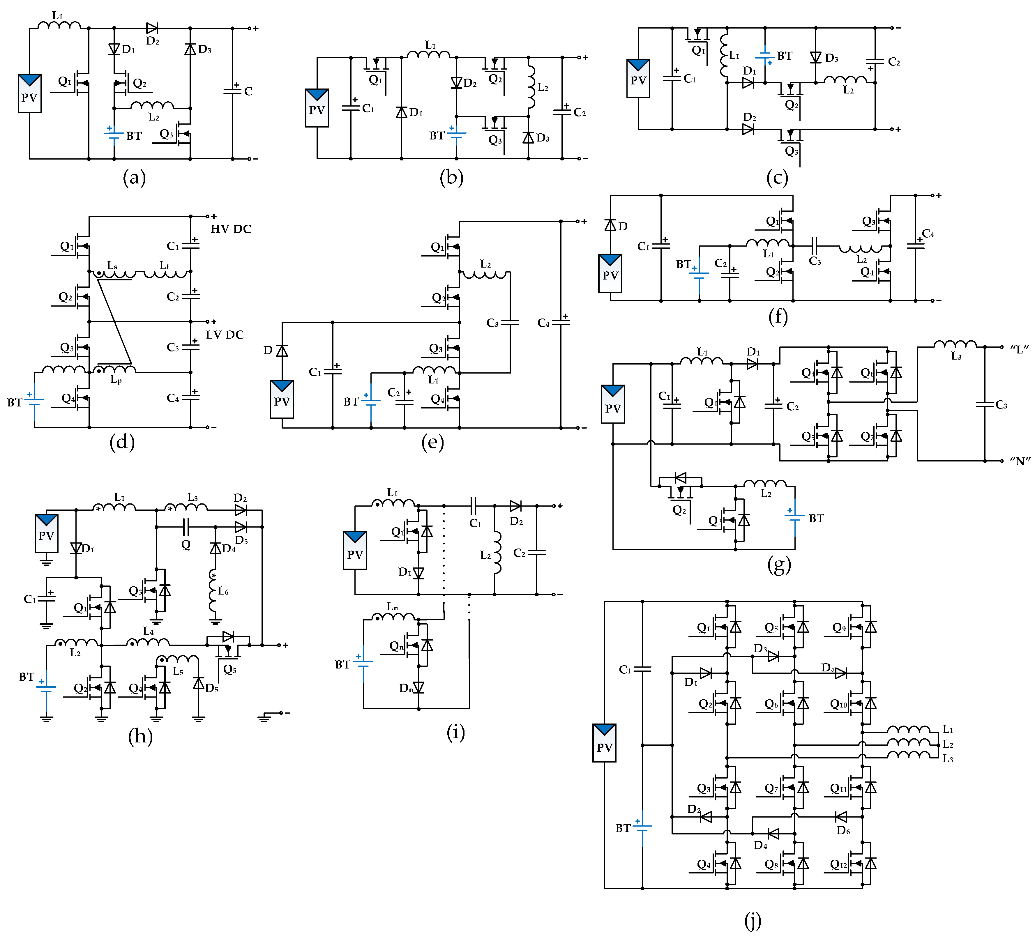
As usual, multi-port solutions are designed for DC–DC [115] or DC–AC [116,117,118,119] applications with renewable sources and energy storage suitable for PV and wind applications as well. Table 9 lists the analytical expressions of the multiport converter parameters shown in Figure 20.
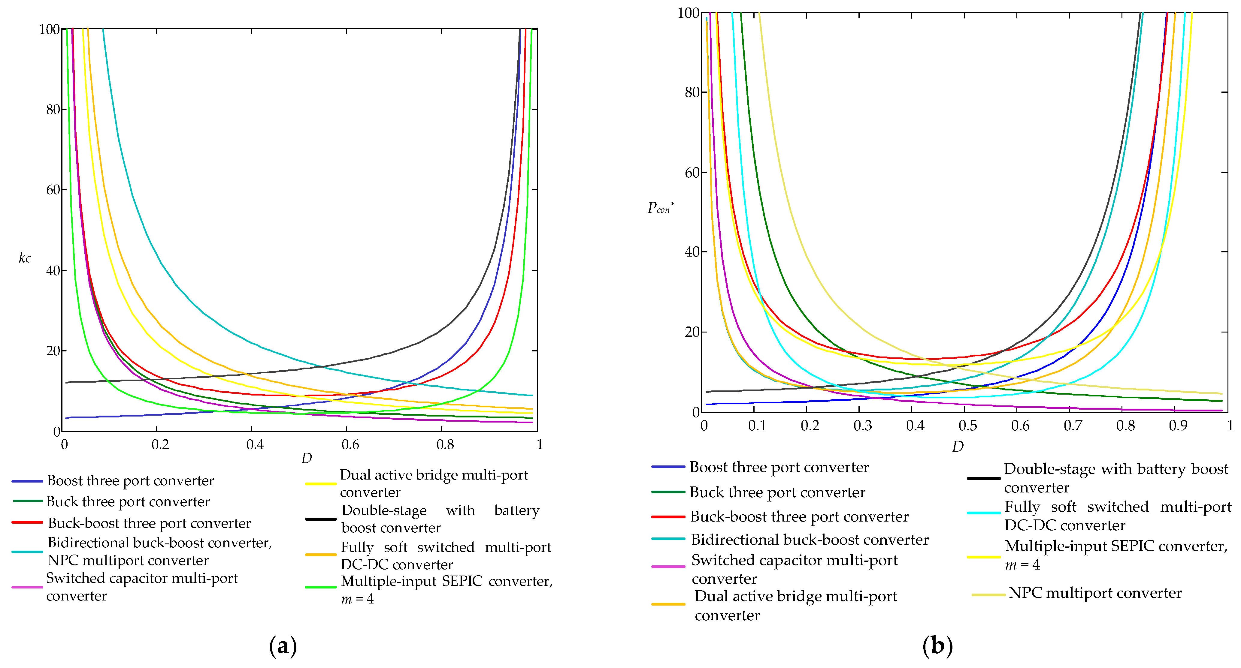
As shown in Figure 21, the lowest values of kC and Pcon* parameters are achieved for converters with basic buck and boost topologies, as well as for more complex switched-capacitor multi-port converters and dual active bridge multi-port converters with soft-switching transistor commutation. However, the analyzed hybrid converters generally have the same number of transistors as common power converters with the same features. The hybrid converters, on the other hand, have about the same power loss and cost as their counterparts with common topologies.
7. Discussion
Derived analytical expressions for cost kc and power loss Pcon* factors are evaluation indicators for selecting the converter topology for PV application design based on duty cycle D. Such parameter representations are strictly related to the converter operation mode and help to define the duty cycle D range of the PV application. However, the comparative analysis of the converter based on kC and Pcon* factors as functions of D, kc = f(D), and Pcon* = f(D), is inconvenient due to their different voltage gains. This is especially true when comparing different types of converters, i.e., buck, boost, and buck-boost converters. It is more informative to analyze parameters kC and Pcon* in some load voltage ranges (UL(min), UL(max)) where the PV application operates for comparative analysis unification. If voltage UL(min) is associated with voltage gain Gmin and voltage UL(max) with voltage gain Gmax, we can define the maximum gain factor Gmax*:
The real gain factor G* of a converter is always varied in the range [1, Gmax*] and may be used as a universal parameter for comparing different types of power converters.
Due to the opportunity to achieve gain factor Gmax* on different duty cycle D ranges [Dmin; Dmax], the range is defined according to providing the lowest cost and/or power loss. According to the specified conditions and obtained results:
- -
- In buck converters, the output voltage maximum value UL(max) is fixed to the input voltage Uin, UL(max) = Uin that corresponds to Dmax = 1;
- -
- In boost converters, the output voltage minimum value UL(min) is fixed to the input voltage Uin, UL(min) = Uin that corresponds to Dmin = 0;
- -
- In buck-boost converters, the lowest values of kc and Pcon* are achieved in the middle of the duty cycle range, D = 0.5. Therefore, for the proper definition of Dmin < 0.5 and Dmax > 0.5, one of the following equations is solved:
The values of UL(min) = f(Dmin) and UL(max) = f(Dmax) are defined depending on the choice of minimization parameter.
After the proposed transformation, parameters kC and Pcon* may be defined based on a function of the parameter G* that varies in the range [1, Gmax*]. Due to this representation, a comprehensive comparison analysis of converters for the defined value of parameter G* may be conducted. However, in real PV applications, because of variations in solar insolation, temperature, battery state of charge, grid voltage, etc., the gain parameter G* varies in range of 1…G*max, and the parameters kc and Pcon* change, respectively. The cost factor kc of the PV application is obviously defined by the largest value of G*max, whereas the power loss parameter Pcon* is defined as an intermediate mean value Pcon(av)* between Pcon*(min) = f(G* = 1) and Pcon*(max) = f(G* = Gmax*). The precise Pcon(av)* value is determined by a weighted function that defines a probability distribution law of G*, p(G*), with values ranging from 1 to Gmax* [120]:
For example, in the case of a continuous uniform distribution, p = 1/(Gmax* − 1) [121] Formula (20) yields:
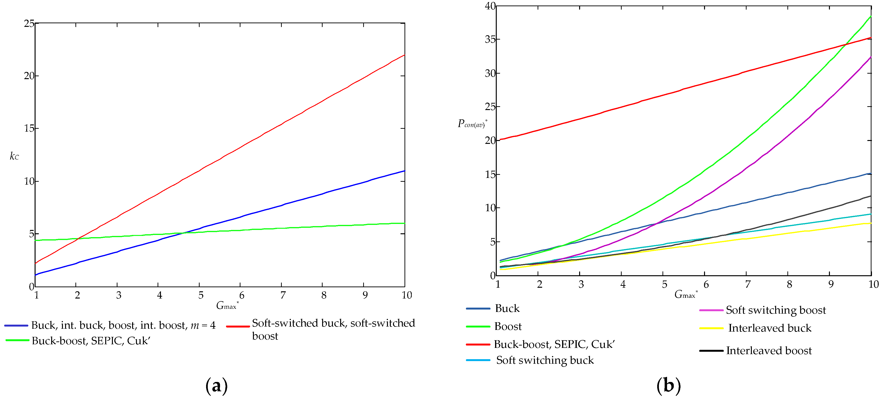
Additionally, analytical expressions of converter efficiency parameters kC and Pcon(av)* for DC–DC converters listed in Table 3 in space of the variable G* are shown in Table 10 and illustrated in Figure 22a,b, respectively.
A representation of the parameters kC and Pcon(av)* with the gain factor G* aids in the estimation of converter features within a given voltage range, as well as the comparison of different converter types (buck, boost and buck-boost). For example, a buck converter has the lowest cost factor kC value for G* ∈ (1; 4.5), whereas a buck-boost converter is preferable for G* ∈ (4.5; ∞) applications. A similar decision may be made for mean power loss Pcon(av)*, which has the lowest value for buck converter modifications in all G* ranges.
Obviously, for different models of semiconductor devices and other probability distribution laws, the results would be different. This allows you to compare power converters based on the PV application’s start-up conditions.
8. Conclusions
Industrial PV solutions contain different kinds of applications designed with power converters as electric energy transformers and interconnectors. Thus, the specific converter requirements vary depending on the application which complicates the selection of the appropriate type of converter for a specific task. The paper highlights generalized criteria that have a critical impact on the efficiency and cost of converter topologies for PV applications that allows performing a comparative analysis in space of two numerical parameters, namely cost and power loss factors, of common PV applications, i.e., grid-on, energy storage, hybrid, and high voltage gain, based on cost and power loss factors.
According to the results of the analysis, the following conclusions are made:
- -
- Basic DC–DC buck and boost topologies, as well as full-bridge topologies for DC-AC applications, have lower cost and power loss factors, whereas more complex interleaved or soft-switching topologies may decrease power loss by increasing the converter total cost;
- -
- For DC–AC applications with a low or medium voltage range, it is advisable to use single-stage DC–AC converters, whereas for wide voltage range applications, two-stage converters have better cost and power loss factors;
- -
- High voltage gain applications suffer from high transistor voltage stress. Therefore, specialized power converter topologies with reduced voltage stress, such as Cockcroft–Walton and Dickson multiplier-based boost converters, boost derived MIESC SC-cell converters, and boost 3SSC cell converters, have the advantage over their counterparts;
- -
- Hybrid converters have approximately the same power loss and cost as power converters with common topologies because of the same number of power transistors;
- -
- For clear analysis of different types of converters, it is better to represent cost and power loss factors in the space of gain factor and analyze the impact of the environment on gain factor probability distribution during operation.
Author Contributions
Conceptualization, I.V.; Formal analysis, I.V. and M.L.; Validation, I.V. and M.L.; Methodology, I.V.; Visualization, M.L. and K.N.; Investigation, M.L., K.N., and B.P.; Writing —original draft, K.N. and B.P.; Resources, O.H.; Writing—review and editing, B.P. and O.H.; Supervision, R.M.S. and O.H; Project administration, R.M.S.; Funding acquisition, R.M.S. All authors have read and agreed to the published version of the manuscript.
Funding
This research was funded by the EU Horizon 2020 Framework Programme Project: 955614—SMARTGYsum—H2020-MSCA-ITN-2020.
Institutional Review Board Statement
Not applicable.
Informed Consent Statement
Not applicable.
Data Availability Statement
Not applicable.
Conflicts of Interest
The authors declare no conflict of interest.
References
- Qazi, A.; Hussain, F.; Rahim, N.A.; Hardaker, G.; Alghazzawi, D.; Shaban, K.; Haruna, K. Towards Sustainable Energy: A Systematic Review of Renewable Energy Sources, Technologies, and Public Opinions. IEEE Access 2019, 7, 63837–63851. [Google Scholar] [CrossRef]
- Statistical Review of World Energy 2021, 70th ed. Available online: https://www.bp.com/content/dam/bp/business-sites/en/global/corporate/pdfs/energy-economics/statistical-review/bp-stats-review-2021-full-report.pdf (accessed on 30 August 2021).
- Shubbak, M.H. Advances in solar photovoltaics: Technology review and patent trends. Renew. Sustain. Energy Rev. 2019, 115, 109383. [Google Scholar] [CrossRef]
- Mehra, V.; Amatya, R.; Ram, R.J. Estimating the value of demand-side management in low-cost, solar micro-grids. Energy 2018, 163, 74–87. [Google Scholar] [CrossRef]
- Romashko, V.J.; Verbitsky, I.V.; Kyrychik, I.I. Energy losses analyze in solar battery maximum power picking system. Tech. Electrodyn. 2014, 4, 55–57. [Google Scholar]
- Clauser, C.; Ewert, M. The renewables cost challenge: Levelized cost of geothermal electric energy compared to other sources of primary energy–Review and case study. Renew. Sustain. Energy Rev. 2018, 82, 3683–3693. [Google Scholar] [CrossRef]
- Tummuru, N.R.; Mishra, M.K.; Srinivas, S. Integration of PV/battery hybrid energy conversion system to the grid with power quality improvement features. In Proceedings of the IEEE International Conference on Industrial Technology (ICIT), Cape Town, South Africa, 25–28 February 2013. [Google Scholar] [CrossRef]
- Hua, C.-C.; Fang, Y.-H.; Wong, C.-J. Improved solar system with maximum power point tracking. IET Renew. Power Gener. 2018, 12, 806–814. [Google Scholar] [CrossRef]
- Darvishzadeh, P.; Redzwan, G.; Ahmadi, R.; Gorji, N.E. Modeling the degradation/recovery of short-circuit current density in perovskite and thin film photovoltaics. Org. Electron. 2017, 43, 247–252. [Google Scholar] [CrossRef]
- Hussaian Basha, C.H.; Rani, C. Performance Analysis of MPPT Techniques for Dynamic Irradiation Condition of Solar PV. Int. J. Fuzzy Syst. 2020, 22, 2577–2598. [Google Scholar] [CrossRef]
- Zhuo, S.; Gaillard, A.; Li, Q.; MA, R.; Paire, D.; Gao, F. Current Ripple Optimization of Four-Phase Floating Interleaved DC-DC Boost Converter under Switch Fault. IEEE Trans. Ind. Appl. 2020, 56, 4214–4224. [Google Scholar] [CrossRef]
- Raghavendra, K.V.G.; Zeb, K.; Muthusamy, A.; Krishna, T.N.V.; Kumar, S.V.S.V.P.; Kim, D.-H.; Kim, M.-S.; Cho, H.-G.; Kim, H.-J. A Comprehensive Review of DC–DC Converter Topologies and Modulation Strategies with Recent Advances in Solar Photovoltaic Systems. Electronics 2020, 9, 31. [Google Scholar] [CrossRef] [Green Version]
- Vinnikov, D.; Chub, A.; Korkh, O.; Liivik, E.; Blaabjerg, F.; Kouro, S. MPPT performance enhancement of low-cost PV microconverters. Sol. Energy 2019, 187, 156–166. [Google Scholar] [CrossRef]
- Kolsi, S.; Samet, H.; Amar, M.B. Design Analysis of DC-DC Converters Connected to a Photovoltaic Generator and Controlled by MPPT for Optimal Energy Transfer throughout a Clear Day. J. Power Energy Eng. 2014, 2, 27–34. [Google Scholar] [CrossRef] [Green Version]
- Bukar, A.L.; Tan, C.W.A. Review on Stand-alone Photovoltaic-Wind Energy System with Fuel Cell: System Optimization and Energy Management Strategy. J. Clean. Prod. 2019, 221, 73–88. [Google Scholar] [CrossRef]
- Bonkile, M.P.; Ramadesigan, V. Power management control strategy using physics-based battery models in standalone PV-battery hybrid systems. J. Energy Storage 2019, 23, 258–268. [Google Scholar] [CrossRef]
- Kumar, A.; Gupta, N.; Gupta, V. A Comprehensive Review on Grid-Tied Solar Photovoltaic System. J. Green Eng. 2017, 7, 213–254. [Google Scholar] [CrossRef]
- Ali Khan, M.Y.; Liu, H.; Yang, Z.; Yuan, X. A Comprehensive Review on Grid Connected Photovoltaic Inverters, Their Modulation Techniques, and Control Strategies. Energies 2020, 13, 4185. [Google Scholar] [CrossRef]
- Mahmood, H.; Michaelson, D.; Jiang, J. A Power Management Strategy for PV/Battery Hybrid Systems in Islanded Microgrids. IEEE J. Emerg. Sel. Top. Power Electron. 2014, 2, 870–882. [Google Scholar] [CrossRef]
- Mira, M.C.; Zhang, Z.; Knott, A.; Andersen, M.A.E. Analysis, Design, Modeling, and Control of an Interleaved-Boost Full-Bridge Three-Port Converter for Hybrid Renewable Energy Systems. IEEE Trans. Power Electron. 2017, 32, 1138–1155. [Google Scholar] [CrossRef] [Green Version]
- Bhattacharjee, A.; Samanta, H.; Banerjee, N.; Saha, H. Development and validation of a real-time flow control integrated MPPT charger for solar PV applications of vanadium redox flow battery. Energy Convers. Manag. 2018, 171, 1449–1462. [Google Scholar] [CrossRef]
- El Aroudi, A.; Haroun, R.; Al-Numay, M.; Huang, M. Multiple-Loop Control Design for a Single-Stage PV-Fed Grid-Tied Differential Boost Inverter. Appl. Sci. 2020, 10, 4808. [Google Scholar] [CrossRef]
- Nassary, M.; Orabi, M.; Ghoneima, M.; El-Nemr, M.K. Single-Phase Isolated Bidirectional AC-DC Battery Charger for Electric Vehicle–Review. In Proceedings of the International Conference on Innovative Trends in Computer Engineering (ITCE), Aswan, Egypt, 2–4 February 2019. [Google Scholar] [CrossRef]
- Sultana, W.R.; Sahoo, S.K.; Sukchai, S.; Yamuna, S.; Venkatesh, D. A review on state of art development of model predictive control for renewable energy applications. Renew. Sustain. Energy Rev. 2017, 76, 391–406. [Google Scholar] [CrossRef]
- Deng, W.; Pei, W.; Li, N.; Zhang, G.; Ding, L.; Kong, L. AC/DC Hybrid Renewable Energy System Coordinated Control and Test Platform. In Proceedings of the 2021 3rd Asia Energy and Electrical Engineering Symposium (AEEES), Chengdu, China, 26–29 March 2021. [Google Scholar] [CrossRef]
- Amir, A.; Amir, A.; Che, H.S.; El Khateb, A.; Rahim, N.A. Comparative Analysis of High Voltage Gain DC-DC Converter Topologies for Photovoltaic Systems. Renew. Energy 2018, 136, 1147–1163. [Google Scholar] [CrossRef] [Green Version]
- Rahman, S.; Khan, I.; Rahman, K.; Al Otaibi, S.; Alkhammash, H.I.; Iqbal, A. Scalable Multiport Converter Structure for Easy Grid Integration of Alternate Energy Sources for Generation of Isolated Voltage Sources for MMC. Electronics 2021, 10, 1779. [Google Scholar] [CrossRef]
- Chen, G.; Liu, Y.; Qing, X.; Wang, F. Synthesis of Integrated Multi-Port DC-DC Converters with Reduced Switches. IEEE Trans. Ind. Electron. 2019, 67, 4536–4546. [Google Scholar] [CrossRef]
- Başoğlu, M.E.; Çakır, B. Comparisons of MPPT performances of isolated and non-isolated DC–DC converters by using a new approach. Renew. Sustain. Energy Rev. 2016, 60, 1100–1113. [Google Scholar] [CrossRef]
- Gorji, S.A.; Sahebi, H.G.; Ektesabi, M.; Rad, A.B. Topologies and Control Schemes of Bidirectional DC–DC Power Converters: An Overview. IEEE Access 2019, 7, 117997–118019. [Google Scholar] [CrossRef]
- Moghassemi, A.; Padmanaban, S. Dynamic Voltage Restorer (DVR): A Comprehensive Review of Topologies, Power Converters, Control Methods, and Modified Configurations. Energies 2020, 13, 4152. [Google Scholar] [CrossRef]
- Ansari, S.; Chandel, A.; Tariq, M. A Comprehensive Review on Power Converters Control and Control Strategies of AC/DC Microgrid. IEEE Access 2020, 9, 17998–18015. [Google Scholar] [CrossRef]
- Undeland, M.N.; Robbins, W.P.; Mohan, N. Power Electronics. In Converters, Applications, and Design, 3rd ed.; John Whiley & Sons: Hoboken, NJ, USA, 1995. [Google Scholar]
- Ha, K.; Lee, C.; Kim, J.; Krishnan, R.; Oh, S.G. Design and development of brushless variable speed motor drive for low cost and high efficiency. Proc. IAS Conf. 2006, 4, 1649–1656. [Google Scholar] [CrossRef]
- IEC 61730-1; Photovoltaic (PV) Module Safety Qualification-Part 1: Requirements for Construction. CENELEC: Brussels, Belgium, 2018.
- IEC 61730-2; Photovoltaic (PV) Module safety Qualification-Part 2: Requirements for Testing. CENELEC: Brussels, Belgium, 2018.
- IEC 62109-1; Safety of Power Converters for Use in Photovoltaic Power Systems–Part 1: General Requirements. CENELEC: Brussels, Belgium, 2010.
- IEC 62109-2; Safety of power Converters for Use in Photovoltaic Power Systems-Part 2: Particular Requirements for Inverters. CENELEC: Brussels, Belgium, 2011.
- Wang, G.; Wang, F.; Magai, G.; Lei, Y.; Huang, A.; Das, M. Performance comparison of 1200V 100A SiC MOSFET and 1200V 100A silicon IGBT. In Proceedings of the 2013 IEEE Energy Conversion Congress and Exposition, Denver, CO, USA, 15–19 September 2013. [Google Scholar] [CrossRef] [Green Version]
- Datasheet of the Transistor C2M0080170P. Available online: https://cms.wolfspeed.com/app/uploads/2020/12/C2M0080170P.pdf (accessed on 9 October 2021).
- Erickson, R.; Maksimovic, D. Fundamentals of Power Electronics, Ser. Power Electronics; Springer: Berlin/Heidelberg, Germany, 2001. [Google Scholar]
- Datasheet of the diode C5D25170H. Available online: https://cms.wolfspeed.com/app/uploads/2020/12/C5D25170H.pdf (accessed on 9 October 2021).
- Jain, S.; Agarwal, V. A Single-Stage Grid-Connected Inverter Topology for Solar PV Systems with Maximum Power Point Tracking. IEEE Trans. Power Electron. 2007, 22, 1928–1940. [Google Scholar] [CrossRef] [Green Version]
- Altin, N.; Ozdemir, S.; Komurcugil, H.; Sefa, I.; Biricik, S. Two-stage grid-connected inverter for PV systems. In Proceedings of the 2018 IEEE 12th International Conference on Compatibility, Power Electronics and Power Engineering, Doha, Qatar, 10–12 April 2018. [Google Scholar] [CrossRef]
- Zebarjadi, M.; Askarzadeh, A. Optimization of a reliable grid-connected PV-based power plant with/without energy storage system by a heuristic approach. Sol. Energy 2016, 125, 12–21. [Google Scholar] [CrossRef]
- Xiao, W.; El Moursi, M.S.; Khan, O.; Infield, D. Review of grid-tied converter topologies used in photovoltaic systems. IET Renew. Power Gener. 2016, 10, 1543–1551. [Google Scholar] [CrossRef] [Green Version]
- Zhang, Y..; Sen, P.C. A new soft-switching technique for buck, boost, and buck~boost converters. IEEE Trans. Ind. Appl. 2003, 39, 1775–1782. [Google Scholar] [CrossRef]
- Verbytskyi, I.; Bondarenko, O.; Liivik, E. Control features of multi cell-type current regulator for resistance welding. In Proceedings of the 2017 IEEE 58th International Scientific Conference on Power and Electrical Engineering of Riga Technical University (RTUCON), Doha, Qatar, 10–12 April 2018. [Google Scholar] [CrossRef]
- Jyotheeswara Reddy, K.; Sudhakar, N. High Voltage Gain Interleaved Boost Converter With Neural Network Based MPPT Controller for Fuel Cell Based Electric Vehicle Applications. IEEE Access 2018, 6, 3899–3908. [Google Scholar] [CrossRef]
- Zeb, K.; Uddin, W.; Khan, M.A.; Ali, Z.; Ali, M.U.; Christofides, N.; Kim, H.J. A comprehensive review on inverter topologies and control strategies for grid connected photovoltaic system. Renew. Sustain. Energy Rev. 2018, 94, 1120–1141. [Google Scholar] [CrossRef]
- Keyhani, H.; Toliyat, H.A. Single-Stage Multi string PV Inverter With an Isolated High-Frequency Link and Soft-Switching Operation. IEEE Trans. Power Electron. 2014, 29, 3919–3929. [Google Scholar] [CrossRef]
- Khodabandeh, M.; Afshari, E.; Amirabadi, M. A Single-Stage Soft-Switching High-Frequency AC-Link PV Inverter: Design, Analysis, and Evaluation of Si-based and SiC-based Prototypes. IEEE Trans. Power Electron. 2018, 34, 2312–2326. [Google Scholar] [CrossRef]
- Lopez, O.; Freijedo, F.D.; Yepes, A.G.; Fernandez-Comesana, P.; Malvar, J.; Teodorescu, R.; Doval-Gandoy, J. Eliminating ground current in a transformerless photovoltaic application. IEEE Trans. Energy Convers. 2010, 25, 140–147. [Google Scholar] [CrossRef]
- Xiao, H.; Xie, S. Leakage current analytical model and application in single-phase transformerless photovoltaic grid-connected inverter. IEEE Trans. Electromagn Compat. 2010, 52, 902–913. [Google Scholar] [CrossRef]
- Zhang, L.; Sun, K.; Xing, Y.; Xing, M. H6 Transformerless Full-Bridge PV Grid-Tied Inverters. IEEE Trans. Power Electron. 2014, 29, 1229–1238. [Google Scholar] [CrossRef]
- Ahmed, M.H.; Wang, M.; Hassan, M.A.S.; Ullah, I. Power Loss Model and Efficiency Analysis of Three-phase Inverter Based on SiC MOSFETs for PV Applications. IEEE Access 2019, 7, 75768–75781. [Google Scholar] [CrossRef]
- Escobar, G.; Martinez-Rodriguez, P.R.; Pool, E.I.; Pena-Quintal, A.E.; Vazquez, G.; Sosa, J.M. A model-based controller of a three-level stacked-cell grid connected converter. In Proceedings of the IECON 2015-41st Annual Conference of the IEEE Industrial Electronics Society, Yokohama, Japan, 9–12 November 2015. [Google Scholar] [CrossRef]
- Mamadaminov, U.M. Advanced Inverters and Their Functionalities for Distributed Solar Generation; Energy Engineering III, Spring; Oregon Institute of Technology: Wilsonville, OR, USA, 2014. [Google Scholar]
- Hidalgo, R.; Abbey, C. Integrating distributed generation with Smart Grid enabling technologies. In Proceedings of the IEEE PES Conference on Innovative Smart Grid Technologies Latin America SGT LA, Medellin, Colombia, 19–21 October 2011. [Google Scholar] [CrossRef]
- Talha, M.; Amir, A.; Raihan, S.R.S.; Abd Rahim, N. Grid-connected photovoltaic inverters with low-voltage ride through for a residential-scale system: A review. Int. Trans. Electr. Energy Syst. 2020, 31, e12630. [Google Scholar] [CrossRef]
- Taul, M.G.; Wang, X.; Davari, P.; Blaabjerg, F. An Overview of Assessment Methods for Synchronization Stability of Grid-Connected Converters Under Severe Symmetrical Grid Faults. IEEE Trans. Power Electron. 2019, 34, 9655–9670. [Google Scholar] [CrossRef] [Green Version]
- Geddada, N.; Karanki, S.B.; Mishra, M.K. Synchronous reference frame based current controller with SPWM switching strategy for DSTATCOM applications. In Proceedings of the 2012 IEEE International Conference on Power Electronics, Drives and Energy Systems (PEDES), Bengaluru, India, 16–19 December 2012. [Google Scholar] [CrossRef]
- Chappa, H.; Thakur, T. Voltage instability detection using synchrophasor measurements: A review. Int. Trans. Electr. Energy Syst. 2020, 30, 12343. [Google Scholar] [CrossRef]
- Calleja, H.; Jimenez, H. Performance of a grid connected PV system used as active filter. Energy Convers. Manag. 2004, 45, 2417–2428. [Google Scholar] [CrossRef]
- Verbytskyi, Y.V. Double Fourier series using for calculating modulating signals spectrum. Tekhnichna Elektrodynamika 2014, 4, 96–98. [Google Scholar]
- Adewuyi, O.B.; Shigenobu, R.; Ooya, K.; Senjyu, T.; Howlader, A.M. Static voltage stability improvement with battery energy storage considering optimal control of active and reactive power injection. Electr. Power Syst. Res. 2019, 172, 303–312. [Google Scholar] [CrossRef]
- Pinnangudi, B.; Kuykendal, M.; Bhadra, S. Smart Grid Energy Storage. Power Grid 2017, 93–135. [Google Scholar] [CrossRef]
- Liu, S.; Xie, X.; Yang, L. Analysis, Modeling and Implementation of a Switching Bi-directional Buck-Boost Converter Based on Electric Vehicle Hybrid Energy Storage for V2G System. IEEE Access 2020, 8, 65868–65879. [Google Scholar] [CrossRef]
- Pakkiraiah, B.; Sukumar, G.D. Research Survey on Various MPPT Performance Issues to Improve the Solar PV System Efficiency. J. Sol. Energy 2016, 2016, 8012432. [Google Scholar] [CrossRef] [Green Version]
- Yang, J.-H.; Jeong, K.-I.; Kwon, J.-M. Energy storage system with PV generation and online UPS functions. In Proceedings of the 2014 IEEE 36th International Telecommunications Energy Conference (INTELEC), Vancouver, BC, Canada, 28 September–2 October 2014. [Google Scholar] [CrossRef]
- Li, K.; Zhao, J.; Ma, Q.; Xu, H. Hierarchy control of power quality for wind–battery energy storage system. IET Power Electron. 2014, 7, 2123–2132. [Google Scholar] [CrossRef]
- Li, X.; Wang, S. A review on energy management, operation control and application methods for grid battery energy storage systems. CSEE J. Power Energy Syst. 2019, 7, 1026–1040. [Google Scholar] [CrossRef]
- Hannan, M.A.; Hoque, M.M.; Hussain, A.; Yusof, Y.; Ker, P.J. State-of-the-Art and Energy Management System of Lithium-Ion Batteries in Electric Vehicle Applications: Issues and Recommendations. IEEE Access 2018, 6, 19362–19378. [Google Scholar] [CrossRef]
- Ortúzar, M.; Dixon, J.; Moreno, J. Ultracapacitor-Based Auxiliary Energy System for an Electric Vehicle: Implementation and Evaluation. IEEE Trans. Ind. Electron. 2007, 54, 2147–2156. [Google Scholar] [CrossRef]
- Fernandez, G. A Bidirectional Buffered Charging Unit for EV’s (BBCU). In Proceedings of the International Power Electronics Conference (IPEC-Niigata 2018-ECCE Asia), Niigata, Japan, 20–24 May 2018. [Google Scholar] [CrossRef]
- Schupbachj, R.M.; Bald, C. Comparing DC-DC Converters for Power Management in Hybrid Electric Vehicles. In Proceedings of the IEEE International Electric Machines and Drives Conference, Madison, WI, USA, 1–4 June 2003; Volume 3, pp. 1369–1374. [Google Scholar] [CrossRef]
- Czogalla, J.; Li, J.; Sullivan, C.R. Automotive Application of Multi-Phase Coupled-Inductor DC-DC Converter. In Proceedings of the IEEE Industry Applications Conference, Salt Lake City, UT, USA, 12–16 October 2003; Volume 3, pp. 1524–1529. [Google Scholar] [CrossRef]
- Farhangi, B.; Toliyat, H.A. Modeling and Analyzing Multiport Isolation Transformer Capacitive Components for Onboard Vehicular Power Conditioners. IEEE Trans. Ind. Electron. 2015, 62, 3134–3142. [Google Scholar] [CrossRef]
- Inoue, S.; Akagi, H. A Bi-Directional DC/DC Converter for an Energy Storage System. In Proceedings of the APEC 07-Twenty-Second Annual IEEE Applied Power Electronics Conference and Exposition, Anaheim, CA, USA, 25 February–1 March 2007. [Google Scholar] [CrossRef]
- Xu, X.; Khambadkone, A.M.; Oruganti, R. A Soft-Switched Back-to-Back Bi-directional DC/DC Converter with an FPGA based Digital Control for Automotive applications. In Proceedings of the IECON 2007-33rd Annual Conference of the IEEE Industrial Electronics Society, Taipei, Taiwan, 5–8 November 2007. [Google Scholar] [CrossRef]
- Jang, S.-J.; Lee, T.W.; Lee, W.C.; Won, C.Y. Bidirectional DC to DC Converters for Fuel Cell Generation System. Power Electron. Spec. Conf. 2004, 6, 4722–4728. [Google Scholar] [CrossRef]
- Lin, B.R.; Hung, T.L. Single-phase half-bridge converter topology for power quality compensation. Electr. Power Appl. IEE Proc. 2002, 149, 351–359. [Google Scholar] [CrossRef]
- Lin, B.R.; Hung, T.L.; Huang, C.H. Bi-directional single-phase half-bridge rectifier for power quality compensation. Electr. Power Appl. IEE Proc. 2003, 150, 397–406. [Google Scholar] [CrossRef]
- Korkh, O.; Blinov, A.; Vinnikov, D. Analysis of Oscillation Suppression Methods in the AC-AC Stage of High Frequency Link Converters. In Proceedings of the IEEE 60th International Scientific Conference on Power and Electrical Engineering of Riga Technical University (RTUCON), Riga, Latvia, 7–9 October 2019. [Google Scholar] [CrossRef]
- Bilgin, B.; Emadi, A.; Krishnamurthy, M. Universal input battery charger circuit for PHEV applications with the simplified controller. In Proceedings of the Applied Power Electronics Conference and Exposition (APEC), Fort Worth, TX, USA, 6–11 March 2011; pp. 815–820. [Google Scholar] [CrossRef]
- Segaran, D.; Holmes, D.G.; McGrath, B.P. High performance bi-directional AC-DC converters for PHEV with minimized DC bus capacitance. In Proceedings of the IECON 37th Annual Conference on IEEE Industrial Electronics Society, Melbourne, Australia, 7–10 November 2011; pp. 3620–3625. [Google Scholar] [CrossRef]
- Odamov, U.O.; Kamilov, M.M.; Niyazov, S.K.; Song, K. Research of the efficiency of the solar battery operations in real exploitation conditions. Sci. Rep. Bukhara State Univ. 2021, 5, 2–17. [Google Scholar] [CrossRef]
- Saidi, A.S.; Slimene, M.B.; Khlifi, M.A. Transient stability analysis of photovoltaic system with experimental shading effects. Eng. Technol. Appl. Sci. Res. 2018, 8, 3592–3597. [Google Scholar] [CrossRef]
- Araujo, S.V.; Torrico-Bascope, R.P.; Torrico-Bascope, G.V.; Menezes, L. Step-up converter with high voltage gain employing three-state switching cell and voltage multiplier. In Proceedings of the 2008 IEEE Power Electronics Specialists Conference, Rhodes, Greece, 15–19 June 2008; pp. 2271–2277. [Google Scholar] [CrossRef]
- Ahmad, J.; Pervez, I.; Sarwar, A.; Tariq, M.; Fahad, M.; Chakrabortty, R.K.; Ryan, M.J. Performance Analysis and Hardware-in-the-Loop (HIL) Validation of Single Switch High Voltage Gain DC-DC Converters for MPP Tracking in Solar PV System. IEEE Access 2021, 9, 48811–48830. [Google Scholar] [CrossRef]
- Arunkumari, T.; Indragandhi, V. An overview of high voltage conversion ratio DC-DC converter configurations used in DC micro-grid architectures. Renew. Sustain. Energy Rev. 2017, 77, 670–687. [Google Scholar] [CrossRef]
- Blinov, A.; Verbytskyi, I.; Zinchenko, D.; Vinnikov, D.; Galkin, I. Modular Battery Charger for Light Electric Vehicles. Energies 2020, 13, 774. [Google Scholar] [CrossRef] [Green Version]
- Norrga, S. Experimental Study of a Soft-Switched Isolated Bidirectional AC DC Converter Without Auxiliary Circuit. IEEE Trans. Power Electron. 2006, 21, 1580–1587. [Google Scholar] [CrossRef]
- Kummari, N.; Chakraborty, S.; Chattopadhyay, S. An Isolated High-Frequency Link Microinverter Operated with Secondary-Side Modulation for Efficiency Improvement. IEEE Trans. Power Electron. 2018, 33, 2187–2200. [Google Scholar] [CrossRef]
- Nayak, P.; Rajashekara, K.; Pramanick, S. Soft-Switched Modulation Technique for a Single-Stage Matrix-Type Isolated DC–AC Converter. IEEE Trans. Ind. Appl. 2019, 55, 7642–7656. [Google Scholar] [CrossRef]
- Tibola, G.; Lemmen, E.; Duarte, J.L.; Barbi, I. Passive Regenerative and Dissipative Snubber Cells for Isolated SEPIC Converters: Analysis, Design, and Comparison. IEEE Trans. Power Electron. 2017, 32, 9210–9222. [Google Scholar] [CrossRef] [Green Version]
- Blinov, A.; Verbytskyi, I.; Peftitsis, D.; Vinnikov, D. Regenerative Passive Snubber Circuit for High-Frequency Link Converters. IEEE J. Emerg. Sel. Top. Ind. Electron. 2021, 3, 252–257. [Google Scholar] [CrossRef]
- Blinov, A.; Kosenko, R.; Chub, A.; Vinnikov, D. Snubberless boost full-bridge converters: Analysis of soft-switching performance and limitations. Int. J. Circ. Theor. Appl. 2019, 47, 884–908. [Google Scholar] [CrossRef]
- Luo, F.L.; Ye, H. Positive output super-lift converters. IEEE Trans. Power Electron. 2003, 18, 105–113. [Google Scholar] [CrossRef]
- Zhang, S.; Xu, J.; Yang, P. A single-switch high gain quadratic boost converter based on voltage-lift technique. In Proceedings of the 10th International Power & Energy Conference (IPEC), Ho Chi Minh City, Vietnam, 12–14 December 2012; pp. 71–75. [Google Scholar] [CrossRef]
- Axelrod, B.; Berkovich, Y.; Shenkman, A.; Golan, G. Diode-capacitor voltage multipliers combined with boost-converters: Topologies and characteristics. IET Power Electron. 2012, 5, 873–884. [Google Scholar] [CrossRef]
- Wu, G.; Ruan, X.; Ye, Z. Nonisolated High Step-Up DC-DC Converters Adopting Switched-Capacitor Cell. IEEE Trans. Ind. Electron. 2015, 62, 383–393. [Google Scholar] [CrossRef]
- Tofoli, F.L.; de Souza Oliveira, D.; Torrico-Bascopé, R.P.; Alcazar, Y.J.A. Novel Nonisolated High-Voltage Gain DC–DC Converters Based on 3SSC and VMC. IEEE Trans. Power Electron. 2012, 27, 3897–3907. [Google Scholar] [CrossRef]
- Zhang, J.; Huang, L.; Shu, J.; Wang, H.; Ding, J. Energy Management of PV-diesel-battery Hybrid Power System for Island Stand-alone Micro-grid. Energy Procedia 2017, 105, 2201–2206. [Google Scholar] [CrossRef]
- Cano, A.; Jurado, F.; Sánchez, H.; Fernández, L.M.; Castañeda, M. Optimal sizing of stand-alone hybrid systems based on PV/WT/FC by using several methodologies. J. Energy Inst. 2014, 87, 330–340. [Google Scholar] [CrossRef]
- Ghaffari, A.; Askarzadeh, A. Design optimization of a hybrid system subject to reliability level and renewable energy penetration. Energy 2020, 193, 116754. [Google Scholar] [CrossRef]
- Noshahr, J.B.; Mohamadi, B.; Kermani, M.; Kermani, M. Operational Planning of Inverter Control in a grid-connected Microgrid with hybrid PV and BESS. In Proceedings of the 2020 IEEE International Conference on Environment and Electrical Engineering and 2020 IEEE Industrial and Commercial Power Systems Europe (EEEIC/I & CPS Europe), Madrid, Spain, 9–12 June 2020. [Google Scholar] [CrossRef]
- Vahid, S.; EL-Refaie, A. A Novel Topology for an Extendable Isolated DC-DC Multi-port Power Converter with a Multipurpose Hybrid Energy Storage System. In Proceedings of the 2020 IEEE Energy Conversion Congress and Exposition (ECCE), Detroit, MI, USA, 11–15 October 2020. [Google Scholar] [CrossRef]
- Pereira, T.; Hoffmann, F.; Zhu, R.; Liserre, M. A Comprehensive Assessment of Multiwinding Transformer-Based DC-DC Converters. IEEE Trans. Power Electron. 2021, 36, 10020–10036. [Google Scholar] [CrossRef]
- Wu, H.; Xing, Y.; Xia, Y.; Sun, K. A family of non-isolated three-port converters for stand-alone renewable power systems. In Proceedings of the IECON 2011-37th Annual Conference of the IEEE Industrial Electronics Society, Melbourne, Australia, 7–10 November 2011. [Google Scholar] [CrossRef]
- Zhang, M.; Xing, Y.; Wu, H.; Lu, Y.; Sun, K. Performance evaluation of a non-isolated bidirectional three-port power converter for energy storage applications. In Proceedings of the 2016 IEEE 8th International Power Electronics and Motion Control Conference (IPEMC-ECCE Asia), Hefei, China, 22–26 May 2016; pp. 2703–2708. [Google Scholar] [CrossRef]
- Sato, Y.; Uno, M.; Nagata, H. Nonisolated Multiport Converters Based on Integration of PWM Converter and Phase-Shift Switched-Capacitor Converter. IEEE Trans. Power Electron. 2019, 35, 455–470. [Google Scholar] [CrossRef]
- Faraji, R.; Farzanehfard, H. Fully Soft Switched Multi-Port DC-DC Converter with High Integration. IEEE Trans. Power Electron. 2020, 36, 1901–1908. [Google Scholar] [CrossRef]
- Kwasinski, A. Identification of Feasible Topologies for Multiple-Input DC-DC Converters. IEEE Trans. Power Electron. 2009, 24, 856–861. [Google Scholar] [CrossRef]
- Balaji, C.; Chellammal, N.; Sanjeevikumar, P.; Bhaskar, M.S.; Holm-Nielsen, J.B.; Leonowicz, Z.; Masebinu, S.O. Non-Isolated High-Gain Triple Port DC-DC Buck-Boost Converter with Positive Output Voltage for Photovoltaic Application. IEEE Access 2020, 2020, 3003192. [Google Scholar] [CrossRef]
- Thang, T.V.; Ahmed, A.; Kim, C.I.; Park, J.H. The flexible system architecture of stand-alone PV power generation with the energy storage device. IEEE Trans. Energy Convers. 2015, 30, 1386–1396. [Google Scholar] [CrossRef]
- Amirabadi, M.; Toliyat, H.A.; Alexander, W.C. A multiport ac link PV inverter with reduced size and weight for a stand-alone application. IEEE Trans. Ind. Appl. 2013, 49, 2217–2228. [Google Scholar] [CrossRef]
- Hassan, S.Z.; Mumtaz, S.; Kamal, T.; Khan, L. Performance of grid-integrated photovoltaic/fuel cell/ electrolyzer/battery hybrid power system. In Proceedings of the 2015 Power Generation Systems and Renewable Energy Technologies, PGSRET, Islamabad, Pakistan, 10–11 June 2015. [Google Scholar] [CrossRef]
- Jayasinghe, S.D.; Vilathgamuwa, D.M.; Madawala, U.K. Diodeclamped three-level inverter-based battery/supercapacitor direct integration scheme for renewable energy systems. IEEE Trans. Power Electron. 2011, 26, 3720–3729. [Google Scholar] [CrossRef]
- Rangu, S.K.; Lolla, P.R.; Dhenuvakonda, K.R.; Singh, A.R. Recent trends in power management strategies for optimal operation of distributed energy resources in microgrids: A comprehensive review. Int. J. Energy Res. 2020, 44, 9889–9911. [Google Scholar] [CrossRef]
- David, F. Probability and Statistics for Computer Science; Springer International Publishing: Berlin/Heidelberg, Germany, 2018; p. 367. [Google Scholar] [CrossRef]
Figure 1.
A family of power curves for different solar insolation powers: (a) as functions of voltage U, P = f (U); (b) as functions of current I, P = f (I).
Figure 1.
A family of power curves for different solar insolation powers: (a) as functions of voltage U, P = f (U); (b) as functions of current I, P = f (I).

Figure 2.
Equivalent load resistance RL(eq) tuning with a power converter.

Figure 3.
The Impact of MPPT input current shape on the value of solar battery power: (a) continuous current; (b) current with ripple ΔI; (c) discontinuous current.
Figure 3.
The Impact of MPPT input current shape on the value of solar battery power: (a) continuous current; (b) current with ripple ΔI; (c) discontinuous current.

Figure 4.
Providing continuous current: (a) natural for power converters with the series-connected inductor L; (b) with an additional capacitor CF for a converter with a series transistor.
Figure 4.
Providing continuous current: (a) natural for power converters with the series-connected inductor L; (b) with an additional capacitor CF for a converter with a series transistor.

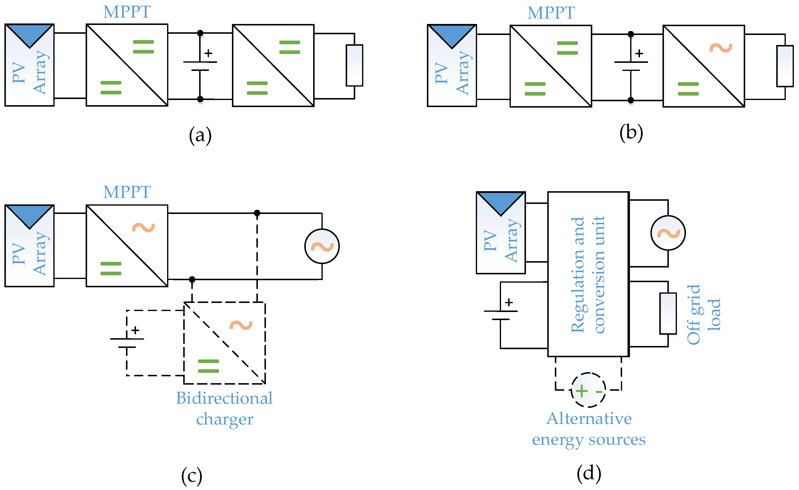
Figure 5.
Common PV applications: (a) standalone DC systems; (b) standalone AC systems; (c) on-grid AC systems with energy storage; and (d) hybrid systems.
Figure 5.
Common PV applications: (a) standalone DC systems; (b) standalone AC systems; (c) on-grid AC systems with energy storage; and (d) hybrid systems.

Figure 6.
The current shape of a transistor in a DC–DC hard-switching converter.

Figure 7.
Transistor current shape for AC–DC and DC–AC hard-switching converters.

Figure 8.
On-grid application structures that are commonly used include: (a) two-stage on-grid application; (b) single-stage on-grid application; and (c) distributed two-stage applications.
Figure 8.
On-grid application structures that are commonly used include: (a) two-stage on-grid application; (b) single-stage on-grid application; and (c) distributed two-stage applications.

Figure 9.
Converter topologies for grid-based applications: (a) buck; (b) boost; (c) buck-boost; (d) SEPIC; (e) Cuk’; (f) soft-switching buck; (g) soft-switching boost; (h) interleaved buck; (i) interleaved boost; (j) half-bridge; (k) full-bridge; (l) three phase full-bridge; (m) H5; (n) H6; (o) HERIC; (p) 3L-NPC; (q) 3L-SC.

Figure 10.
DC–DC converters: (a) cost factor kC; (b) normalized power loss Pcon*.

Figure 11.
DC–AC converters: (a) cost factor kC; (b) normalized power loss Pcon*.

Figure 12.
DC–AC converters: (a) the cost factor kC; (b) the normalized power loss Pcon*.

Figure 13.
The following are typical energy storage converter topologies: (a) single-stage DC–DC application; (b) single-stage DC–AC application; (c) two-stage isolated DC–DC application; (d) two-stage DC–AC application.
Figure 13.
The following are typical energy storage converter topologies: (a) single-stage DC–DC application; (b) single-stage DC–AC application; (c) two-stage isolated DC–DC application; (d) two-stage DC–AC application.

Figure 14.
Converters for single-stage storage applications: (a) half-bridge; (b) Cuk’; (c) SEPIC/Luo; (d) interleaved half-bridge; (e) cascaded half-bridge; (f) half-bridge rectifier with neutral point switch clamped scheme; (g) capacitor clamped three-level; (h) high-frequency-link inverter.
Figure 14.
Converters for single-stage storage applications: (a) half-bridge; (b) Cuk’; (c) SEPIC/Luo; (d) interleaved half-bridge; (e) cascaded half-bridge; (f) half-bridge rectifier with neutral point switch clamped scheme; (g) capacitor clamped three-level; (h) high-frequency-link inverter.

Figure 15.
Converters for two-stage storage applications: (a) dual active bridge; (b) dual active bridge soft-switching; (c) with two voltage-fed half-bridges; (d) combined voltage- half-bridge and current-fed full-bridge; (e) half-bridge and full-bridge; (f) full-bridge DC–AC and dual active bridge DC–DC.

Figure 16.
The cost factor kC and normalized power loss Pcon∗ of DC–DC energy storage (a) Cost factor kC; (b) normalized power loss Pcon* in DC–DC energy storage converters.
Figure 16.
The cost factor kC and normalized power loss Pcon∗ of DC–DC energy storage (a) Cost factor kC; (b) normalized power loss Pcon* in DC–DC energy storage converters.

Figure 17.
The parameters for DC–AC applications (a) Cost factor kC; (b) normalized power loss Pcon* in DC–AC energy storage converters.
Figure 17.
The parameters for DC–AC applications (a) Cost factor kC; (b) normalized power loss Pcon* in DC–AC energy storage converters.

Figure 18.
High voltage gain converters: (a) isolated full-bridge; (b) cascaded boost converter; (c) flyback; (d) LC parallel resonant converter with voltage doubler; (e) super lift voltage converter; (f) modified voltage lift converter; (g) Cockcroft–Walton multiplier based boost converter; (h) Dickson multiplier based boost converter; (i) boost derived MIESC SC-cell converter; (j) boost 3SSC cell converter; (k) buck-boost derived MIESC SC-cell converter.

Figure 19.
In high voltage gain converters: (a) cost factor kC; (b) normalized power loss Pcon*; and (c) voltage gain G.
Figure 19.
In high voltage gain converters: (a) cost factor kC; (b) normalized power loss Pcon*; and (c) voltage gain G.

Figure 20.
Hybrid converters: (a) boost three-port converter; (b) buck three-port converter; (c) buck-boost three-port converter; (d) bidirectional buck-boost converter; (e) switched capacitor multi-port converter; (f) dual active bridge multi-port converter; (g) double-stage with battery boost converter; (h) fully soft-switched multi-port DC–DC converter; (i) multiple-input SEPIC converter; (j) NPC multiport converter.

Figure 21.
Hybrid converter parameters: (a) cost factor kC; (b) normalized power loss Pcon*.

Figure 22.
Comparative analysis of the DC–DC converter’s effectiveness in space of the variable G*: (a) cost factor kC; (b) normalized mean power loss Pcon(av)*.
Figure 22.
Comparative analysis of the DC–DC converter’s effectiveness in space of the variable G*: (a) cost factor kC; (b) normalized mean power loss Pcon(av)*.


Table 1.
Common PV application descriptions and requirements.
| PV Application | Modifications |
|---|---|
| 1. Standalone PV applications [15,16] |
|
| 2. On-grid PV applications [17,18] | |
| 3. Hybrid PV applications [19,20] |
Table 2.
Normalized power loss of the transistor and diode for DC–DC converters.
| Power Loss Type | Converter Type | ||
|---|---|---|---|
| Hard-Switching | Soft-Switching | Resonant | |
| Transistor static power loss, PTst* | |||
| Transistor dynamic power loss, PTd* | 0 | 0 | |
| Diode static power loss, PDst* | |||
| Diode dynamic power loss, PDd* | 0 | 0 | |
Table 3.
The cost factor kC and the normalized power loss for common DC–DC and DC–AC converters.
| Converter Topology | kC | Pcon * |
|---|---|---|
| DC–DC converters | ||
| Buck [12], Figure 9a | ||
| Boost [12], Figure 9b | ||
| Buck-boost, SEPIC, Cuk’ [12], Figure 9c–e | ||
| Soft-switching buck [47], Figure 9f | ||
| Soft-switching boost [47], Figure 9g | ||
| Interleaved buck [48], Figure 9h, m cells | ||
| Interleaved boost [49], Figure 9i, m cells | ||
| DC–AC converters | ||
| Half-bridge [50],Figure 9j | ||
| Full-bridge [50], Figure 9k | ||
| Triple-bridge [50], Figure 9l | ||
| H5 [55], Figure 9m | ||
| H6 [55], Figure 9n | ||
| HERIC [55],Figure 9o | ||
| 3L-NPC [56], Figure 9p | ||
| 3L-SC [57], Figure 9q | ||
Table 4.
The full-bridge converter is used to calculate the cost factor kC and the normalized power loss for single- and two-stage applications.
Table 4.
The full-bridge converter is used to calculate the cost factor kC and the normalized power loss for single- and two-stage applications.
| kC | Pcon * | |
|---|---|---|
| Single-stage application with a full-bridge converter | ||
| Two-stage application with buck and full-bridge converters |
Table 5.
List of additional converter functions.
| Opportunities for Power Grid Control | Converter Function | Control Strategy |
|---|---|---|
| Reactive power control [58] | Independent reactive and active power generation | Sinusoidal pulse width modulation (SPWM), space vector modulation (SVM) or hysteresis modulation in dq or αβ space |
| Voltage stabilization [60,61,62,63,64,65] | Voltage and frequency ride through, voltage sag detection, reactive power generation | For frequency synchronization: zero-crossing method and the phase-locked-loop. For sag detection: RMS value estimator, synchronous rotating reference frame, wavelet, and Fourier transform. For power generation: SPWM, SVM or hysteresis modulation in dq or αβ space |
| Grid power quality control [62] | Controlled injected current | SPWM or hysteresis modulation, frequency synchronization |
Table 6.
A Comparative analysis of single-stage energy storage converter effectiveness.
| Converter Topology | kC | Pcon * |
|---|---|---|
| DC–DC converters | ||
| Half-bridge [74], Figure 14a | ||
| 3L-NPC [75], Figure 9q | ||
| Cuk’ [76], Figure 14b, SEPIC/Luo [76], Figure 14c | ||
| Interleaved half-bridge [77], Figure 14d | ||
| If UBT > Ug → Cascaded half-bridge [78], Figure 14e If UBT < Ug → | ||
| DC–AC converters | ||
| Half-bridge, Figure 9j | ||
| Full-bridge, Figure 9k | ||
| Half-bridge rectifier with neutral point switch clamped scheme [82], Figure 14f | ||
| Capacitor clamped three-level PWM converter [83], Figure 14g | ||
| High-frequency link inverter [84], Figure 14h | ||
Table 7.
A Comparative analysis of the two-stage energy storage converters’ effectiveness.
| Converter Topology | kC | Pcon * |
|---|---|---|
| DC–DC converters | ||
| Dual active bridge, Figure 15a | ||
| Dual active bridge soft-switching [79], Figure 15b | ||
| Converter with two voltage-fed half-bridges [80], Figure 15c | 8 | |
| Combined-voltage half-bridge and current-fed full-bridge [81], Figure 15d | ||
| DC–AC converters | ||
| Half-bridge and full-bridge [85], Figure 15e | ||
| Full-bridge DC–AC and dual active bridge DC–DC [86], Figure 15f | ||
Table 8.
High voltage gain converters: comparative analysis.
| Converter Topology | G | kC | Pcon* |
|---|---|---|---|
| Isolated full-bridge, Figure 18a | nD | ||
| Conventional boost converter, Figure 9b | |||
| Cascaded boost converter [90], Figure 18b | |||
| SEPIC [92], Figure 9d, Flyback [92], Figure 18c | |||
| LC parallel current source converter with voltage doubler [98], Figure 18d | |||
| Super lift voltage converter [99], m cells, Figure 18e | |||
| Modified voltage lift converter [100], m cells, Figure 18f | |||
| Cockcroft–Walton and Dickson multiplier based boost converter [101], m cells, Figure 18g,h | |||
| Boost derived MIESC SC-cell converter [102], m cells, Figure 18i | |||
| Buck-boost derived MIESC SC-cell converter [102], m cells, Figure 18j | |||
| Boost 3SSC cell converter [103], m cells, Figure 18k |
Table 9.
A comparative analysis of the effectiveness of the hybrid converter.
| Converter Topology | kC | Pcon * |
|---|---|---|
| Boost three-port converter [110], Figure 20a | ||
| Buck three-port converter [110], Figure 20b | ||
| Buck-boost three-port converter [110], Figure 20c | ||
| Bidirectional buck-boost converter [111], Figure 20d | ||
| Switched capacitor multi-port converter [112], Figure 20e | ||
| Dual active bridge multi-port converter [112], Figure 20f | ||
| Double-stage with battery boost converter [116], Figure 20g | ||
| Fully soft-switched multi-port DC-DC converter [113], Figure 20h | ||
| Multiple-input SEPIC converter, m cells [114], Figure 20i | ||
| NPC multiport converter [110], Figure 20j |
Table 10.
Comparative analysis of the DC–DC converter’s effectiveness in space of the variable G*.
| Converter Topology | kC | Pcon(av) * |
|---|---|---|
| Buck | ||
| Boost | ||
| Buck-boost, SEPIC, Cuk’ | ||
| Soft-switching buck | ||
| Soft-switching boost | ||
| Interleaved buck | ||
| Interleaved boost |
Publisher’s Note: MDPI stays neutral with regard to jurisdictional claims in published maps and institutional affiliations. |
© 2022 by the authors. Licensee MDPI, Basel, Switzerland. This article is an open access article distributed under the terms and conditions of the Creative Commons Attribution (CC BY) license (https://creativecommons.org/licenses/by/4.0/).
Share and Cite
MDPI and ACS Style
Verbytskyi, I.; Lukianov, M.; Nassereddine, K.; Pakhaliuk, B.; Husev, O.; Strzelecki, R.M. Power Converter Solutions for Industrial PV Applications—A Review. Energies 2022, 15, 3295. https://doi.org/10.3390/en15093295
AMA Style
Verbytskyi I, Lukianov M, Nassereddine K, Pakhaliuk B, Husev O, Strzelecki RM. Power Converter Solutions for Industrial PV Applications—A Review. Energies. 2022; 15(9):3295. https://doi.org/10.3390/en15093295
Chicago/Turabian StyleVerbytskyi, Ievgen, Mykola Lukianov, Kawsar Nassereddine, Bohdan Pakhaliuk, Oleksandr Husev, and Ryszard Michał Strzelecki. 2022. "Power Converter Solutions for Industrial PV Applications—A Review" Energies 15, no. 9: 3295. https://doi.org/10.3390/en15093295
Note that from the first issue of 2016, this journal uses article numbers instead of page numbers. See further details here.