Article

Modeling, Simulation and Analysis of Intermediate Fixed Piezoelectric Energy Harvester

1
School of Mechanical and Power Engineering, Henan Polytechnic University, Jiaozuo 454000, China
2
Office of Educational Research, Shandong Traffici Technician College, Linyi 276000, China
*
Author to whom correspondence should be addressed.
Energies 2022, 15(9), 3294; https://doi.org/10.3390/en15093294
Submission received: 17 March 2022 / Revised: 17 April 2022 / Accepted: 27 April 2022 / Published: 30 April 2022

Abstract

:
To address the problem that piezoelectric energy harvesters are difficult to apply in certain environments, this paper establishes the theoretical study of the intermediate fixed disc piezoelectric energy harvester (IFDPEH) based on the unimorph under concentrated force. The reliability of the model was indirectly verified by numerical simulation and Computer-Aided Engineering (CAE) simulation. The effects of load, radius ratio (piezoelectric layer/intermediate support), thickness ratio (piezoelectric layer/total thickness), and elastic modulus ratio (substrate/piezoelectric layer) on electrical energy were studied. The results indicate that the radius/thickness ratios of the IFDPEH based on aluminum and beryllium bronze are 0.05/0.31 and 0.05/0.48, respectively. In addition, through parameter comparison, it is found that the most important parameters affecting IFDPEH power are radius ratio and large load. The results are demonstrated to be meaningful for broadening the application of piezoelectric energy harvesters by the derived closed-form equations for the electrical energy along the diameters of the piezoelectric discs in the z-direction.

1. Introduction

In view of the self-supply requirements of low-power electronic products, devices under harsh conditions such as the seaside or unmanned desert areas, self-driving cars, and household safety systems, as well as the difficulty in replacing the built-in batteries in the equipment and the resulting pollution of the environment, almost ubiquitous forms of available environmental energy—such as the liquid flow of waves, the swing of air objects, the operation of mechanical equipment, and the vibration of cars, and so on—has gradually attracted attention. The energy-harvesting devices based on the principles of electromagnetic, electrostatic, capacitance, friction, and piezoelectric has become a focus in the field of energy recovery [1]. The energy conversion of a piezoelectric vibrator is to convert vibration energy into electrical energy by using its piezoelectric effect. Due to the sensitivity of the low-frequency piezoelectric energy harvester to vibration, it can be easily placed in microelectromechanical systems (MEMS) [2]. It has many advantages, such as relatively simple structure and large functional density, high conversion efficiency, no electromagnetic interference, no pollution, and so on. Therefore, research on using piezoelectric energy-harvesting devices to replace the batteries of micro-generators for the power supply of wireless sensors and other devices has also moved to the center of major scientific research platforms.
As well as summarized by Kim and Mourad, scholars have done a lot of significant research on piezoelectric materials and structure analysis on beams, disks, and cymbals [3,4]. However, most relevant studies are based on the previous two forms of piezoelectric vibrators to improve their structure, section shape, stress mode, and other aspects, rather than exploring energy harvest technology. Tudor et al. designed two prototypes for the power supply of MEMS, conducted theoretical research and experiments on resonance frequency, open circuit, and load output varying with amplitude, and tested them on an automobile engine, which could generate a peak power of 3.9 mW [5]. Zhang et al. proposed the application of periodic gravity and rotating wheel road noise excitation. The test results demonstrated that at the low frequency of 6 Hz, the output power of the equipment was 12 and 50 times higher than that of road-noise-only excitation or periodic gravity excitation, respectively [6]. Cheol et al. set a cantilever beam behind the front bumper decorative grille of new energy electric vehicles. The real vehicle test shows that when the vehicle runs at 90 km/s, the voltage of the device can reach 60.25 V and the power can reach 18.7 mW. While in [7], a cymbal-shaped energy harvester was mounted on a car tire. Test results showed that the maximum output voltage, and power, together with electrical energy of the device is about 3.5 V, 2.8 mW, and 24 J/rev respectively, which provide energy to two sensors of the tire. Atthapol et al. designed a light-duty electric multi-purpose bicycle based on piezoelectric. The test shows that the device can store 3200 mA with a 5 V battery, and output 11.5 V voltage and 1.2 mA current at the normal cycle speed generated at 13.6 mW [8]. A novel piezoelectric disk energy harvester was developed by [9]. Under the test condition of 10 g mass and 9.8 m/s2 acceleration, the maximum output power of the energy harvester with 19 mm diameter and 6 mm hole can reach 8.34 mW. Li et al. made a double piezoelectric energy harvester. Experiments showed the optimal peaking voltage along with the root mean square power of 36.07 V, 5.31 V, and 5.47 mW, 0.05 mW, for the two energy harvesters, respectively, under constant driving conditions (1000 r/min) [10]. Abdel et al. designed a piezoelectric stacked suspension spring device. The results showed that when the vehicle is excited by a resonant frequency of 1.46 Hz and an acceleration amplitude of 0.5 g, the maximum voltage as well as the power value captured in the quarter car model are 19.11 volts and 36.74 mW. The recovered voltage is increased by 75.6% as well as the power by 53.4% for the semi-vehicle model [11].
With the acceleration of the demand for piezoelectric applications, how to improve the electric energy of piezoelectric structure devices has become a hot issue. Therefore, the majority of scholars have been enriched in theoretical modeling. From Andrzej et al [12]. the finite element method is used to solve the axis-symmetric piezoelectric twin wafer problem, and it is theoretically proved that the electrical signal generated by the circular transducer clamped on the outer edge of the piezoelectric wafer is zero. Then in [13], they assume that the strain of the lead zirconate titanate (PZT) plate presented a linear distribution with the thickness. The parameters such as the size of PZT substrate and bonding layer material and their corresponding mechanical properties were analyzed. Under the same structure, Kim S et al. studied the impacts of geometric parameters along with electrode configurations to obtain electrical energy from piezoelectric plates under a uniform distributed load and carried out subsequent experimental verification [14,15]. In Prasad et al.’s study, the equilibrium equation of a piezoelectric unimorph circular diaphragm containing one or more piezoelectric layers is derived, and the closed solution is obtained when the disc piezoelectric layer diameter is smaller than the diameter of the substrate [16]. Wischke et al. applied the coupled-field finite element method to evaluate the electrical energy from disks of different sizes [17]. A similar research program for harvesters was presented in [18], which is an analysis model of the piezoelectric composite circular diaphragm by using the Raleigh Method, and analyzed the optimal structural parameters of a piezoelectric harvester under the boundary conditions of simply supported and fixed supports was analyzed. Finally, it was concluded that simply supported piezoelectric energy capture devices have higher energy recovery efficiency and are more suitable for energy acquisition applications. Changki et al. also further studied the structure and obtained the expression of the total output power of the device under a uniform load. In their study, attention was paid to key elements, such as the bonding layer in the composite piezoelectric oscillator, and the factors that may reduce the energy collection performance were analyzed. The optimal design parameters were determined and verified by experiments [19,20]. While most scholars focus on linear parameter analysis, Dai et al. focused on the use of the Eulerian Lagrange principle and the Galerkin method, the nonlinear distributed parameter model of the energy harvester under the combined action of base vibratior and vortex-induced vibrations was established to study the performance of the electrical load resistance, wind speed, as well as base acceleration for the coupling frequency, electro-mechanical damping, along with the energy harvester performance [21]. Skaliukh et al. modeing of nonuniform pre-polarized piezoelectric ceramic sensors. It is shown that the initial polarization field has an important effect on the displacement and deformation distribution of the converter [22]. Yuan et al. studied the nonlinear behavior established a lumped parameter model of a piezoelectric energy harvester with a fixed circular composite plate around the periphery and determined the parameters through experiments [23]. Thereafter, Iman. et al. comprehensively modeled the fixed circular plate around the piezoelectric layer by taking into account the electric field generated along the diameter of the piezoelectric layer to optimize the polarization boundary of the clamped piezoelectric disc. The findings show that the location of the zero-strain point is related to the radius of the piezoelectric layer and the substrate [24].
In recent years, most scholars are very interested in piezoelectric energy harvesters under the action of the fluid. Xie et al. established a mathematical model of output charge and voltage of piezoelectric plates by the Airy linear wave theory in combination with the elastic beam model, which can be applied in ocean wave energy recovery and achieve up to 30 W recovered power [25]. Wahad et al. also modeled and simulated it, and obtained the relationship between its open-circuit output voltage, maximum deflection, as well as internal stress and device size, and applied pressure amplitude [26]. On the other hand, Moeenfard et al. used the random vibration theory to model a stationary disk piezoelectric energy harvester around the plate and obtained the statistical parameters of the dynamic characteristics of the plate and the captured energy voltage [27]. Hegde et al. modeled a circular piezoelectric energy harvester in acoustic energy mode and analyzed the effects of equivalent circuit parameters, deflection values, linearity, and frequency response on its voltage. Experiments showed that a customized piezoelectric crystal speaker could generate a voltage of 40 mV at 140 dB [28]. Eghbali et al. proposed two kinds of piezoelectric energy harvesters which contributed to the efficiency of the energy harvesters. Through finite element modeling and experimental tests, it is shown that the two improved resonant frequencies are much lower than the traditional resonators, and the amplification coefficients can reach 10.2 V and 13.3 V [29].
Summarizing the above review, for the piezoelectric energy harvester under the action of fluid, whether it is linear or nonlinear problems, most scholars are around the surrounding fixed disc piezoelectric energy harvester as the research object to discuss the change of electrical parameters. However, with the wide application of the piezoelectric energy harvester in the environment, its fixation mode will also change under special environmental conditions. Aiming to broaden the applicability of the piezoelectric energy harvester, this paper presents an intermediate fixed-disc piezoelectric energy harvester (IFDPEH). For this theoretical study, a comprehensive analytical model was included, followed by a parametric study to improve the electrical energy of the IFDPEH. The electric energy equation of the IFPEH is derived by analyzing boundary conditions under concentrated force. This change is a function of radius ratio (PZT layer to substrate ratio), thickness ratio (PZT layer to piezoelectric vibrator ratio), elastic modulus ratio (substrate to PZT ratio), and concentrated force amplitude.

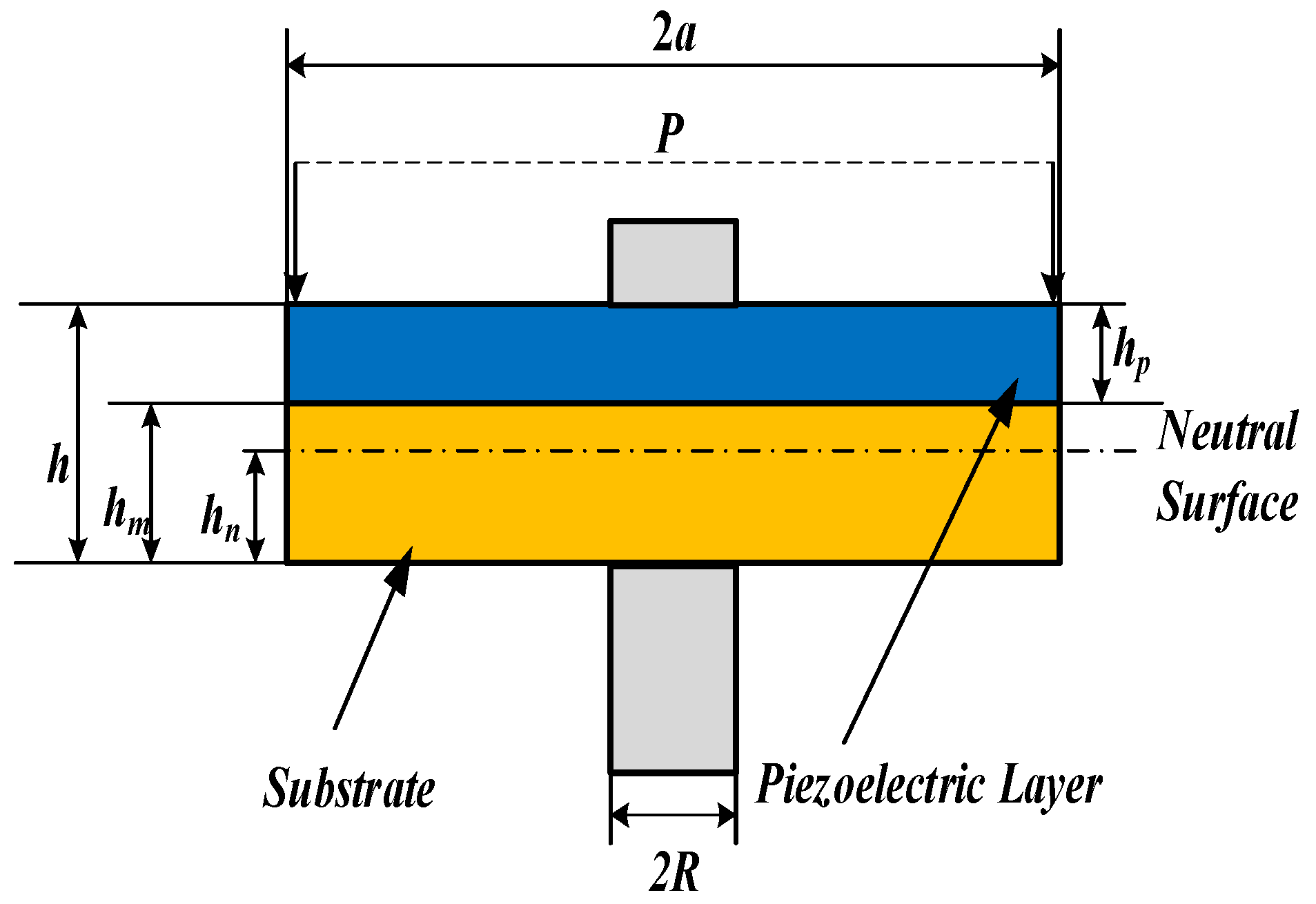
2. Mechanical Modelling

Compared with the commonly used cantilever piezoelectric energy harvester, the circular piezoelectric energy harvester has the advantages of strong bearing capacity and simple series structure [30]. When the PZT is subjected to external force, it will bend and deform, thus generating a charge on its surface. The amount of charge depends on its stress distribution and deformation shape [31]. For the IFDPEH shown in Figure 1, there are few directly available conclusions. Under the condition of intermediate fixation, the disc-shaped piezoelectric vibrator generates deflection deformation under external force, and the deflection is the largest at the outer edge of the PZT. The structure has a piezoelectric layer bonded to the metal substrate. This paper considers that the bonding between layers is perfect, and the thickness is not large, so it is neglected. At this point, the electrical energy generation is determined by the material, thickness, external load, as well as boundary conditions of the piezoelectric vibrator.
In Figure 1, a is the radius of the PZT, b is the radius of the substrate, and R = la is the radius of the intermediate support bar. While h is the overall thickness, hp = bh is the thickness of the piezoelectric ceramic, the metal base plate thickness is hm = (1 − bh, and l and β are defined as the radius ratio and the thickness ratio. In addition, hc is the length from the neutral surface to the bottom of the substrate, and the subscripts m, p, and c respectively represent the metal substrate, piezoelectric ceramics, and the composite structure bonded between the substrate and PZT.
According to the literature [32], the distance between the middle boundary layer and the bottom of the substrate is as follows:
h n = E m h 3 / ( 1 v m 2 ) + E p ( h 2 h m 2 ) / ( 1 v p 2 ) 2 [ E m h m / ( 1 v m 2 ) + E p h p / ( 1 v p 2 ) ] = φ h φ = ζ ( 1 β ) 2 ( 1 v p 2 ) + [ 1 ( 1 β ) 2 ] ( 1 v m 2 ) 2 [ ζ ( 1 β ) ( 1 v p 2 ) + β ( 1 v p 2 ) ]
where Em and Ep are Young’s modulus of the substrate and PZT materials, respectively. z is the ratio of Young’s modulus. vm and vp are Poisson’s ratio of substrate and PZT materials, respectively. φ is the thickness coefficient of the neutral surface.
Referring to the plate-shell theory and related knowledge [33,34], the governing equations of transverse deflection, bending, and shear of circular plate under concentrated force P are obtained as follows:
4 w = 1 r d d r ( r d d r ( 1 r d d r ( r d w d r ) ) ) = 0
w = A r 2 + B r 2 ln r + C ln r + K
where w is the deflection of the plate in the z-direction, and r is the distance from the plate center to the deformation point.
According to the Equation (3), the bending moment, the moment in angular direction, and the shear force, are as follows:
M r = D c ( d 2 w d r 2 + v c r d w d r )
M θ = D c ( v c d 2 w d r 2 + 1 r d w d r )
Q = D c ( d 3 w d r 3 + 1 r d 2 w d r 2 1 r 2 d w d r )
where D c = E c h 3 / ( 12 ( 1 v c 2 ) ) is the equivalent bending stiffness of the composite circular plate. Ec and vc are the equivalent young’s modulus and equivalent Poisson’s ratio, respectively.
According to the literature [13], the equivalent Young’s modulus Ec and equivalent Poisson’s ratio vc of the PZT-metal composite parts can be summed as follows:
E c = E p [ β + ( 1 β ) ζ + ( 1 β ) β ζ ( v m v p ) 2 β ( 1 v m 2 ) + ( 1 β ) ( 1 v p 2 ) ζ ]
v c = ( 1 v m 2 ) β v p + ( 1 β ) ( 1 v p 2 ) v m ζ β ( 1 v m 2 ) + ( 1 β ) ( 1 v p 2 ) ζ
Under the action of concentrated force, the boundary condition of IFDPH is
{ w = 0 , d w / d r = 0 ( r = R ) Q = P , M = 0 ( r = a )
The expressions of A, B, C, and K can be obtained according to Equations (4)–(9), as shown in Table 1.

3. Electric Energy Calculation Model

According to the generalized Hooke’s Law in the elastic theory of materials, when a shear force is ignored, the differential equation of a small deflection of piezoelectric ceramics can be written as follows [35]:
σ 1 = E p 1 v p 2 ( S 1 + v p S 2 ) σ 2 = E p 1 v p 2 ( S 2 + v p S 1 )
where σ1 is the radial stress component; σ2 is the circumferential stress component; and S1 is the radial strain, and S2 is the circumferential strain, which can be expressed as:
S 1 = z d 2 w d r 2 ; S 2 = z r d w d r
This IFDPEH is made up of PZT-4, elastic substrate, and intermediate struts. Referring to the piezoelectric constitutive equation, the relationship between the parameters in the electromechanical coupling effect of this structure can be obtained [36]:
S 1 = S 11 D T 1 + S 12 D T 2 + S 2 D 3 S 2 = S 12 D T 1 + S 11 D T 1 + S 1 D 3 E 3 = g 31 ( T 1 + T 2 ) + β 33 T D 3
Using Equations (11) and (12), the following can be obtained:
{ T 1 = E p 1 v p 2 ( S 1 + v p S 2 ) g 31 E p 1 v p D 3 T 2 = E p 1 v p 2 ( S 2 + v p S 1 ) g 31 E p 1 v p D 3 E 3 = g 31 E p z 1 v p 2 ( d 2 w d r 2 + 1 r d w d r ) + β 33 T D 3
where T1 and T2 are the radials and compressive stress of the piezoelectric materials, respectively. E3 and D3 are the electric field strength together with the potential shift along the z-direction, respectively; E p = 1 / S 11 D is the Young’s modulus of the piezoelectric material. S 11 D and S 22 D are elastic compliance coefficients, and g 31 is the piezoelectric stress constant.
We can get the electric field strength of the IFDPEH under the action of external forces from Equations (10) to (13) as:
E 3 = β 33 S D 3 g 31 E p z 1 v p [ 4 A + 4 B ( 1 + ln r ) ]
where β 33 S = β 33 T [ 1 + ( ( 2 g 31 2 E p ) / ( β 33 T ( 1 v p ) ) ) ] is the permittivity.
By integrating Equation (14) in the z direction, we get:
V g = ( h h n ) h n h m E 3 d z = h β β 33 S D 3 + h 2 β E p g 31 ( 2 2 α β ) 2 ( 1 v P ) × [ 4 A + 4 B ( 1 + ln r ) ]
The expression of the electric displacement can be solved as:
D 3 = V g h β β 33 S ( 2 2 α β ) g 31 E p h 2 β 33 S ( 1 v P ) × [ 4 A + 4 B ( 1 + ln r ) ]
The charge generated by the piezoelectric electrode can be obtained by surface integration of Equation (16). Since the electrode is on the equipotential surface here, the voltage is not affected by the change of radius of the vibrator under compression, and hence the charge quantity can be expressed as follows:
Q 0 = 2 π R a D 3 r d r = C f r V g π ( 2 2 α β ) g 31 E p h ( 1 v P ) β 33 S × [ 2 A ( a 2 R 2 ) + B ( ( 2 a 2 ln a ) ( 2 R 2 ln R ) + ( a 2 R 2 ) ) ]
where C f r = π ( a 2 R 2 ) / ( β h β 33 S ) is the free capacitance of the IFDPEH. Equation (17) is the charge generated when the concentrated force and the external electric field coexist. For the IFDPEH, the applied electric field Vg is 0, so the charges generated under the concentrated force is:
Q = 2 π R a D 3 r d r = C f r V g π ( 2 2 α β ) g 31 E p h ( 1 v P ) β 33 S × [ 2 A ( a 2 R 2 ) + B ( ( 2 a 2 ln a ) ( 2 R 2 ln R ) + ( a 2 R 2 ) ) ]
With the relationship from charge to voltage, the expression for the open-circuit voltage generated by IFDPEH under the action of a concentrated force can be obtained as follows:
V = Q C f r = ( 2 2 α β ) β g 31 E p h 2 ( 1 v P ) ( a 2 R 2 ) × [ 2 A ( a 2 R 2 ) + B ( 2 a 2 ( 1 + ln a ) 2 R 2 ( 1 + ln R ) ( a 2 R 2 ) ) ]
Therefore, the electric energy generated by the IFDPEH under concentrated force can be written as follows:
E = 1 2 C f r V 2 = π β h 3 2 β 33 S ( a 2 R 2 ) × [ ( 2 2 α β ) E p g 31 ( 1 v P ) · H ] 2
H = 2 A ( a 2 R 2 ) + B ( ( 2 a 2 ln a ) ( 2 R 2 ln R ) + ( a 2 R 2 ) )

4. Results and Discussion

Aiming to better analyze the deformation curve of the IFDPEH piezoelectric layer under a concentrated force source and the influence factors of electric energy, the impacts of several geometric parameters will be studied in this paper. The diameter as well as the thickness of the IFDPEH, are 34 mm and 0.55 mm, respectively. The related performance parameters of the piezoelectric plate and substrate materials are shown in Table 2.

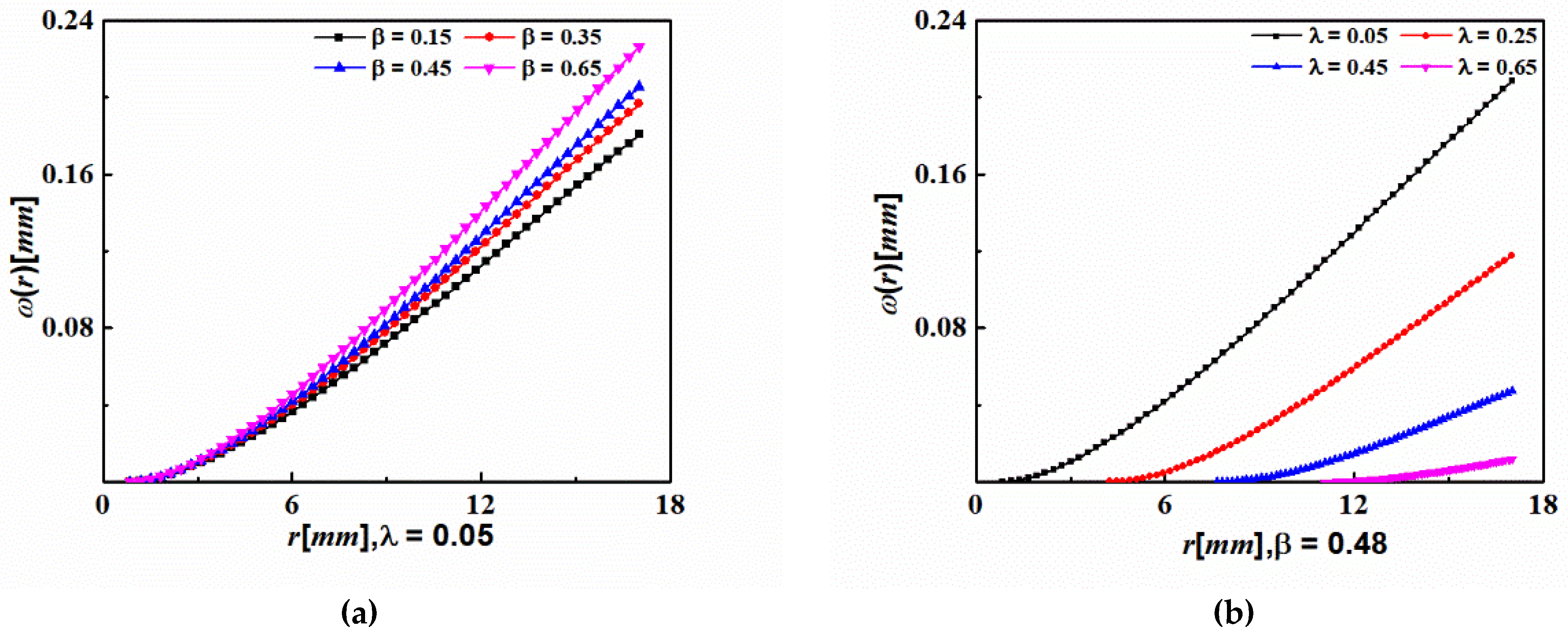
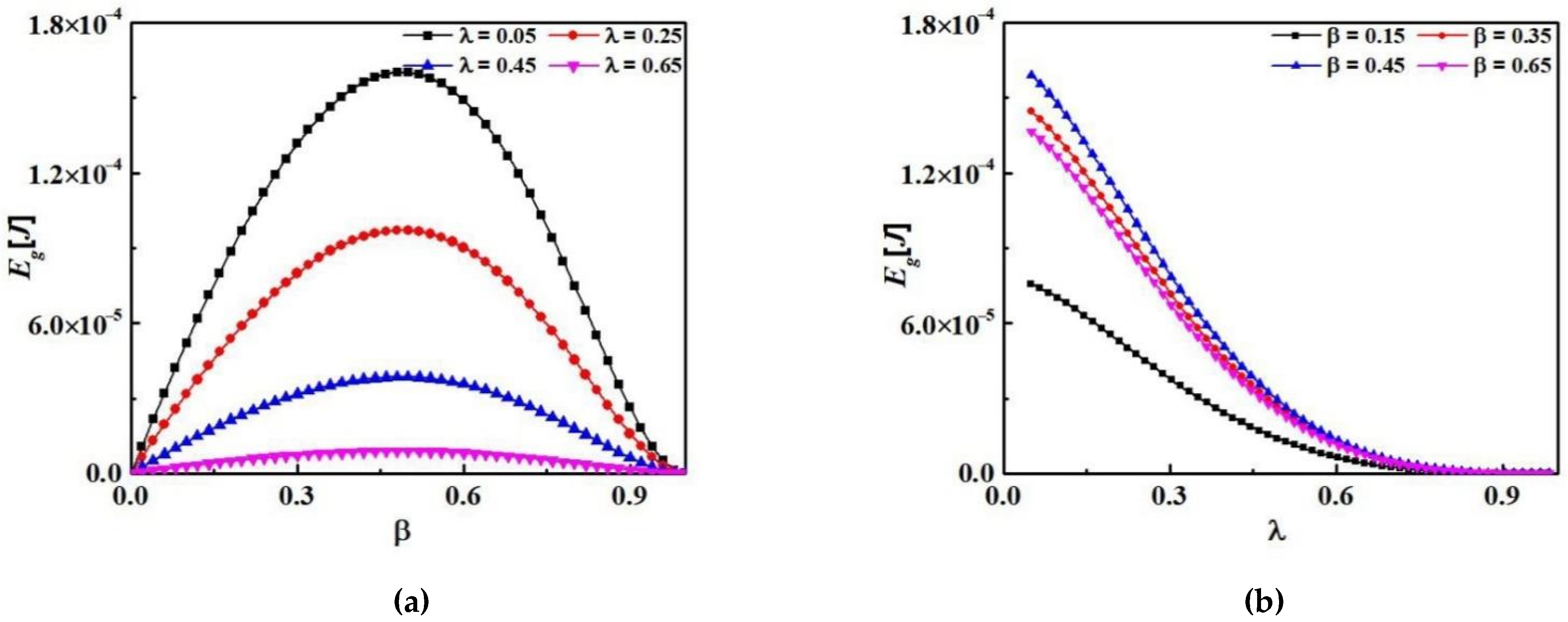
4.1. Parameter Analysis under Constant Load

In Figure 2, using Equation (20), the electric energy of the IFDPEH under concentrated force (25 N) is shown as a function of the radius ratio (λ) and the thickness ratio (β). Obviously, each radius ratio has an optimal thickness ratio to maximize its electrical energy, and its values are different. When the radius ratio is too large, that is, the PZT area is too small, and the electrical energy decreases sharply. When the thickness ratio is too large or too small, the electrical energy even decreases to zero, which is similar to clamped piezoelectric circular plates [31]. When the radius ratio is 0.05 and the thickness ratio is 0.48, the maximum electric energy can be obtained, as shown in Figure 3.
Figure 3 shows the deflection curves of the IFDPEH under different structural parameters, indicating that the radius ratio and thickness ratio have effects on the deformation deflection of the IFDPEH. When the radius ratio is constant, the deflection increases as the thickness ratio decreases. With a constant thickness ratio, the deflection increases as the radius ratio decreases. The larger the radius ratio is, the more obvious the decreasing trend of the deflection is. In comparison, the radius ratio has more influence on the deflection.
Figure 4 shows the 2D model of the IFDPEH under concentrated load when the radius ratio is 0.3. Figure 4 clearly shows that in the 2D model simulation (through the operation of Ansys workbench software, including the finite element division, path setting, and modelling analysis), the deflection is the smallest at the inner boundary of r = R. On the contrary, the maximum deflection is at the outer boundary of r = a. Therefore, this is basically consistent with Figure 3, which also proves the reliability of the mathematical model in the paper.
In Figure 5, since the electric energy of the IFDPEH is related to its deflection under load deformation, when the radius ratio is close to 1 (equivalent to the concentrated force acting on the middle support), the structure has no piezoelectric layer, and the electric energy is naturally 0. To avoid this situation, the structural design of the piezoelectric energy harvester should be as small as possible. On the other hand, when the radius is relatively small (that is, equivalent to a point similar to the middle support), the deflection deformation of IFDPEH is relatively large, that is, the electric energy will also produce the optimal value. Besides, when the radius ratio is constant, the electrical energy begins to decrease when the thickness ratio reaches 0.48, that is, the optimal thickness ratio corresponding to the optimal electrical energy is 0.48.
According to the above mathematical model, the deflection line and electric energy of the IFDPEH under concentrated loads are also sensitive by the piezoelectric layer and the metal substrate material. It can be seen from Figure 6 that due to the different structural dimensions of the intermediate fixed piezoelectric vibrator, the elastic modulus ratio corresponding to the optimal electric energy is also different. When the radius ratio is constant, although the best modulus of elasticity ratio decreases with the decrease of thickness ratio, the corresponding maximum electric energy increases. On the other hand, with the determination of the thickness ratio, the optimal modulus of elasticity ratio hardly influences the radius ratio (or even shows no change), but the corresponding greatest electrical energy increases as the radius ratio decreases. The phenomenon shown in Figure 5 that is the electrical energy of the IFDPEH being affected by the radius ratio, thickness ratio, as well as elastic modulus ratio, in this respect, this is the equivalent of a clamped piezoelectric circular plate. In fact, the elastic modulus ratio is the same, and the thickness ratio is different. The stiffness of the IFPDEH leads to different deflections under a load, resulting in different electrical energy. However, as the thickness ratio is small, the decrease of the elastic modulus ratio of the substrate can improve the electrical energy generated by the IFDPEH under a concentrated load.
Figure 7 indicates the influence curve of the thickness ratio in the electric energy generation of the IFDPEH between aluminum and beryllium bronze substrates. For a steady value of the radius ratio, the optimal thickness ratio of the maximum electrical energy corresponding in the IFDPEH with substrate is also different. In particular, when the thickness ratio reaches 0.31, the electric energy generated by the aluminum substrate is the largest, and the difference with that of beryllium bronze substrate is also the largest. Moreover, since IFDPEH uses a small modulus of elasticity ratio, it can be seen to play a role in improving its electrical energy when 0 < β < 0.48, but as the thickness ratio continues to increase, the electrical energy generated by the substrate with a smaller elastic modulus decreases.

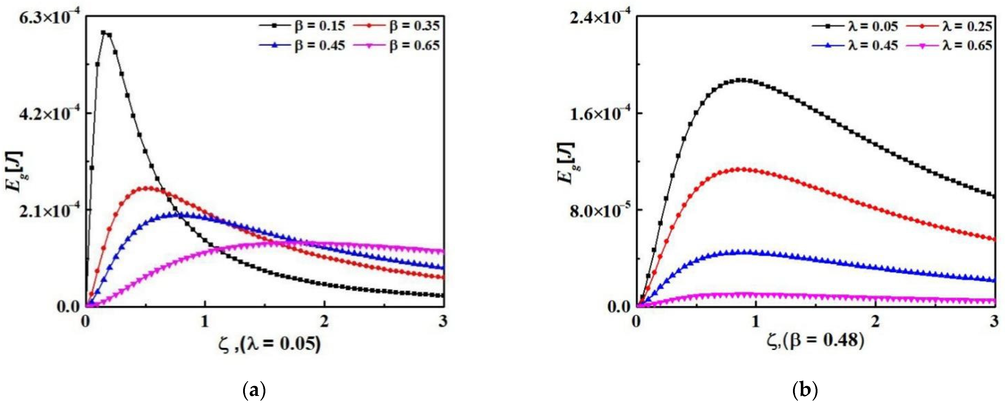
4.2. Parameter Analysis under Variable Load

At this point, the substrate is made of beryllium bronze, as the thickness ratio is constant, so electrical energy increases in response to increasing load or radius ratio, and electrical energy increases while the substrate thickness ratio remains constant, as shown in Figure 8. On the other hand, the smaller the radius ratio, the greater the amplitude of electric energy increase in the same load. It can be observed that in a certain thickness ratio, the smaller the radius ratio, the greater the increase of electrical energy. The reason for this situation is that the PZT layer with a smaller radius ratio has a larger coverage range, and the deflection deformation of the IFDPEH is affected, so the electric energy gradually increases.

5. Conclusions

Based on the deformation equation along the z-direction of the piezoelectric disk diameter, a closed-form equation was derived for the electric energy of the IFDPEH. Moreover, the numerical simulation of it under different substrates is carried out, and the factors affecting the electric energy are analyzed. These parameters are the radius ratio of the piezoelectric layer and the intermediate support, the thickness ratio of the piezoelectric layer and the substrate layer, the elastic modulus ratio of different substrates, and the variable load. On the other hand, the deflection change cloud chart of the 2D model is established by CAE simulation software, which indirectly verifies the accuracy of the model. When the ratio of the radius of the intermediate support to the radius of the piezoelectric plate is (0.05) and the external force is the same, the radius/thickness ratios of the IFDPEH based on aluminum and beryllium bronze are 0.05/0.31 and 0.05/0.48, respectively. To verify the effectiveness of the results, the optimal parameters affecting the optimal electrical energy of the IFDPEH are compared with the results reported in other forms of piezoelectric harvester [18,24]. Our results show that:
  • Compared with the clamped piezoelectric circular plates, the influence of parameter thickness ratio and elastic modulus ratio on electrical energy is similar.
  • The difference is as follows:
    (1)
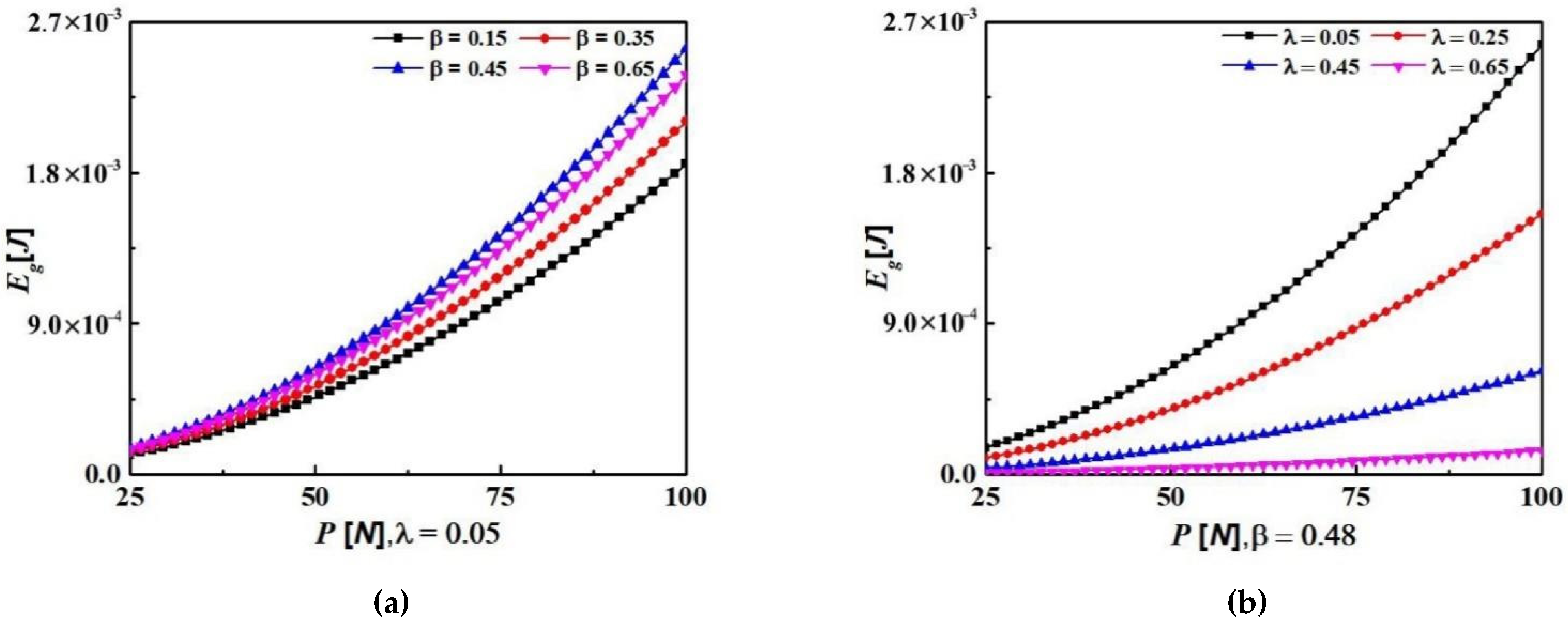
    When the thickness ratio is constant, with the gradual increase of the load, the smaller the radius ratio, the greater the increase of electric energy. This is because the smaller the radius ratio is, the larger the coverage of the piezoelectric layer is, thus affecting the deflection deformation of the IFDPEH, and the electric energy gradually increases.
    (2)
    In this paper, the influence of radius ratio on the IFDPEH’s electrical energy is greater than the thickness ratio when the load condition is certain.
    (3)
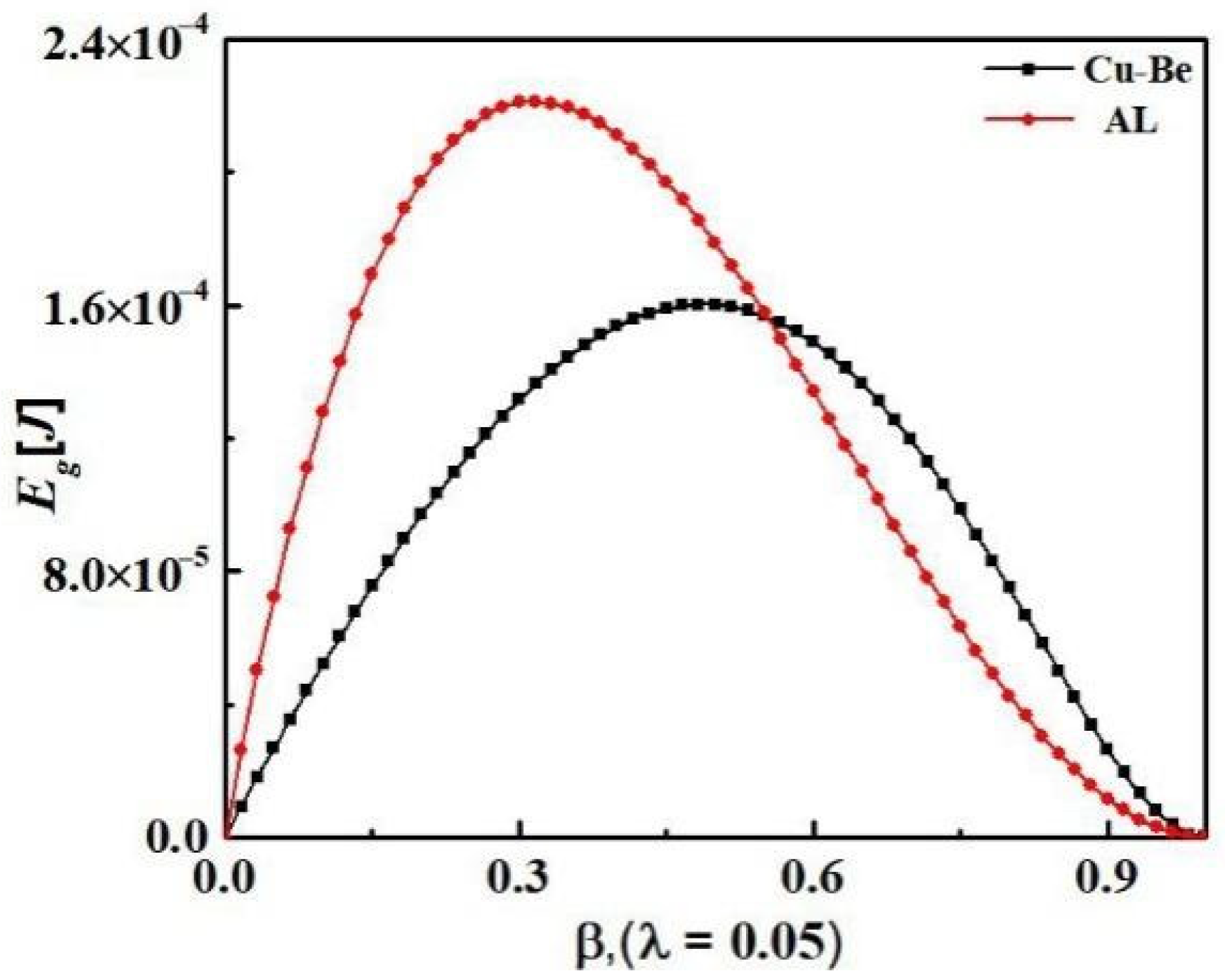
    The use of metal substrates with low modulus of elasticity and small radii to maximize the load strength within the allowable stress range of the material helps to increase the electrical energy of the IFDPEH under concentrated forces.

Author Contributions

Conceptualization, B.L. and Y.W.; methodology, formal analysis, Y.W.; data curation, software, Y.L.; investigation, resources, Y.Z.; writing—original draft preparation, Y.W.; writing—review and editing, B.L. and Y.W.; funding acquisition, B.L. All authors have read and agreed to the published version of the manuscript.

Funding

This research was funded by the Science and Technology Research Project of Henan Province, grant number 182102310843; and the Fundamental Research Funds for the Universities of Henan Province, grant number NSFRF200403.

Institutional Review Board Statement

Not applicable.

Informed Consent Statement

Not applicable.

Data Availability Statement

Not applicable.

Conflicts of Interest

The authors declare no conflict of interest.

References

  1. Ryu, H.; Yoon, H.J.; Kim, S.W. Hybrid Energy Harvesters: Toward Sustainable Energy Harvesting. Adv. Mater. 2019, 31, 1802898. [Google Scholar] [CrossRef] [PubMed]
  2. Covaci, C.; Gontean, A. Piezoelectric Energy Harvesting Solutions: A Review. Sensors 2020, 20, 3512. [Google Scholar] [CrossRef] [PubMed]
  3. Kim, H.S.; Kim, J.; Kim, J. A review of piezoelectric energy harvesting based on vibration. Int. J. Precis. Eng. Manuf. 2011, 12, 1129–1141. [Google Scholar] [CrossRef]
  4. Al-Yafeai, D.; Darabseh, T.; Mourad, A.I. A State-of-the-Art Review of Car Suspension-Based Piezoelectric Energy Harvesting Systems. Energies 2020, 13, 2336. [Google Scholar] [CrossRef]
  5. Glynne-Jones, P.; Tudor, M.J.; Beeby, S.P.; White, N.M. An electromagnetic, vibration-powered generator for intelligent sensor systems. Sens. Actuators A Phys. 2004, 110, 344–349. [Google Scholar] [CrossRef] [Green Version]
  6. Zhang, Y.; Zheng, R.; Shimono, K.; Kaizuka, T.; Nakano, K. Effectiveness Testing of a Piezoelectric Energy Harvester for an Automobile Wheel Using Stochastic Resonance. Sensors 2016, 16, 1727. [Google Scholar] [CrossRef] [PubMed] [Green Version]
  7. Esmaeeli, R.; Aliniagerdroudbari, H.; Hashemi, S.R.; Alhadri, M.; Zakri, W.; Batur, C.; Farhad, S. Design, modeling, and analysis of a high performance piezoelectric energy harvester for intelligent tires. Int. J. Energy Res. 2019, 43, 5199–5212. [Google Scholar] [CrossRef]
  8. Jettanasen, C.; Songsukthawan, P.; Ngaopitakkul, A. Development of Micro-Mobility Based on Piezoelectric Energy Harvesting for Smart City Applications. Sustainability 2020, 12, 2933. [Google Scholar] [CrossRef] [Green Version]
  9. Xu, C.; Li, Y.; Yang, T. Optimization of Non-Uniform Deformation on Piezoelectric Circular Diaphragm Energy Harvester with a Ring-Shaped Ceramic Disk. Micromachines 2020, 11, 963. [Google Scholar] [CrossRef]
  10. He, L.; Zhao, D.; Li, W.; Wu, X.; Cheng, G. A dual piezoelectric energy harvester with contact and non-contact driven by inertial wheel. Mech. Syst. Signal Process. 2021, 146, 106994. [Google Scholar] [CrossRef]
  11. Darabseh, T.; Al Yafeai, D.; Mourad, A.H.I.; Almaskari, F. Piezoelectric method-based harvested energy evaluation from car suspension system: Simulation and experimental study. Energy Sci. Eng. 2021, 9, 417–433. [Google Scholar] [CrossRef]
  12. Dobrucki, A.B.; Pruchnicki, P. Theory of piezoelectric axisymmetric bimorph. Sens. Actuators A Phys. 1997, 58, 203–212. [Google Scholar] [CrossRef]
  13. Li, S.; Chen, S. Analytical analysis of a circular PZT actuator for valveless micropumps. Sens. Actuators A Phys. 2003, 104, 151–161. [Google Scholar] [CrossRef]
  14. Kim, S.; Clark, W.W.; Wang, Q. Piezoelectric Energy Harvesting with a Clamped Circular Plate: Analysis. J. Intell. Mater. Syst. Struct. 2005, 16, 847–854. [Google Scholar] [CrossRef]
  15. Kim, S.; Clark, W.W.; Wang, Q. Piezoelectric Energy Harvesting with a Clamped Circular Plate: Experimental Study. J. Intell. Mater. Syst. Struct. 2005, 16, 855–863. [Google Scholar] [CrossRef]
  16. Prasad, S.A.N.; Gallas, Q.; Horowitz, S.; Homeijer, B.; Sankar, B.V.; Cattafesta, L.N.; Sheplak, M. Analytical Electroacoustic Model of a Piezoelectric Composite Circular Plate. AIAA J. 2006, 44, 2311–2318. [Google Scholar] [CrossRef]
  17. Wischke, M.; Goldschmidtboeing, F.; Woias, P. A low cost generator concept for energy harvesting applications. In Proceedings of the TRANSDUCERS 2007—2007 International Solid-State Sensors, Actuators and Microsystems Conference, Lyon, France, 10–14 June 2007; pp. 875–878. [Google Scholar]
  18. Junwu, K.; Jinhao, Q.; Kehong, T.; Kongjun, Z.; Chenghui, S. Modeling and simulation of piezoelectric composite diaphragms for energy harvesting. Int. J. Appl. Electromagn. Mech. 2009, 30, 95–106. [Google Scholar] [CrossRef]
  19. Mo, C.; Radziemski, L.J.; Clark, W.W. Analysis of piezoelectric circular diaphragm energy harvesters for use in a pressure fluctuating system. Smart Mater. Struct. 2010, 19, 025016. [Google Scholar] [CrossRef]
  20. Mo, C.; Radziemski, L.J.; Clark, W.W. Experimental validation of energy harvesting performance for pressure-loaded piezoelectric circular diaphragms. Smart Mater. Struct. 2010, 19, 075010. [Google Scholar] [CrossRef]
  21. Dai, H.L.; Abdelkefi, A.; Wang, L. Piezoelectric energy harvesting from concurrent vortex-induced vibrations and base excitations. Nonlinear Dyn. 2014, 77, 967–981. [Google Scholar] [CrossRef]
  22. Skaliukh, A.S.; Soloviev, A.N.; Oganesyan, P.A. Modeling of Piezoelectric Elements with Inhomogeneous Polarization in ACELAN. Ferroelectrics 2015, 483, 95–101. [Google Scholar] [CrossRef]
  23. Yuan, T.C.; Yang, J.; Chen, L.Q. Nonlinear dynamics of a circular piezoelectric plate for vibratory energy harvesting. Commun. Nonlinear Sci. Numer. Simul. 2018, 59, 651–656. [Google Scholar] [CrossRef]
  24. Mehdipour, I.; Honarvar, F. Finding the optimum polarization boundary line for enhancing the performance of clamped piezoelectric circular plates. Appl. Math. Model. 2021, 91, 1141–1153. [Google Scholar] [CrossRef]
  25. Xie, X.D.; Wang, Q.; Wu, N. Energy harvesting from transverse ocean waves by a piezoelectric plate. Int. J. Eng. Sci. 2014, 81, 41–48. [Google Scholar] [CrossRef]
  26. Rahman, W.U.; Khan, F.U. Modeling and simulation of flow-based circular plate type piezoelectric energy harvester for pipeline’s monitoring. In Proceedings of the 2019 22nd International Multitopic Conference (INMIC), Islamabad, Pakistan, 29–30 November 2019; pp. 1–6. [Google Scholar]
  27. Bakhtiari-Shahri, M.; Moeenfard, H. Energy harvesting from unimorph piezoelectric circular plates under random acoustic and base acceleration excitations. Mech. Syst. Signal Process. 2019, 130, 502–523. [Google Scholar] [CrossRef]
  28. Hegde, V.; Yellampalli, S.S.; Ravikumar, H.M. Simulation, mathematical modeling, fabrication and experimental analysis of piezoelectric acoustic sensor for energy harvesting applications. Microsyst. Technol. 2020, 26, 1613–1623. [Google Scholar] [CrossRef]
  29. Eghbali, P.; Younesian, D.; Moayedizadeh, A.; Ranjbar, M. Study in circular auxetic structures for efficiency enhancement in piezoelectric vibration energy harvesting. Sci. Rep. 2020, 10, 16338. [Google Scholar] [CrossRef]
  30. Shuang, W.; Baozhan, L. Mechanism and status of typical piezoelectric energy harvester. Electron. Compon. Mater. 2018, 37, 1–11. (In Chinese) [Google Scholar]
  31. Wang, S.; Kan, J.; Wang, B.; Yang, Z.; Ling, R.; Xu, H.; Cheng, G. Modeling and simulation of a piezodisc generator under central load. Int. J. Appl. Electromagn. Mech. 2013, 41, 349–360. [Google Scholar] [CrossRef]
  32. Zheng, L.; Zhigang, Y.; Junwu, K.; Lisheng; Bo, Y.; Dan, L. Theoretical and simulation analysis of piezoelectric liquid resistance captor filled with pipeline. Mater. Res. Express 2018, 5, 35517. [Google Scholar] [CrossRef] [Green Version]
  33. Timoshenko, S.; Woinowsky-Krieger, S. Theory of Plates and Shells; McGraw-Hill: New York, NY, USA, 1959. [Google Scholar]
  34. Vinson. Structural Mechanics: The Behavior of Plates and Shells (Book); Wiley: Hoboken, NJ, USA, 1974. [Google Scholar]
  35. Du, X.; Zhang, M.; Chang, H.; Wang, Y.; Yu, H. Micro windmill piezoelectric energy harvester based on vortex-induced vibration in tunnel. Energy 2022, 238, 121734. [Google Scholar] [CrossRef]
  36. Uchino, K. Advanced Piezoelectric Materials; Woodhead Publishing: Sawston, UK, 2010. [Google Scholar]
Figure 1. Structure of intermediate fixed disk piezoelectric energy harvester (IFDPEH).
Energies 15 03294 g001
Figure 2. Effects of radius ratio as well as thickness ratio on IFDPEH electrical energy.
Energies 15 03294 g002
Figure 3. Effects of radius ratio as well as thickness ratio on the deformation curve of IFPDEH. (a) When the radius ratio is 0.05, the thickness ratios are 0.15, 0.35, 0.45 and 0.65 respectively; (b) When the thickness ratio is 0.48, the radius ratios are 0.05, 0.25, 0.45 and 0.65 respectively.
Energies 15 03294 g003
Figure 4. Deformation of the IFPDEH under concentrated load along the z-direction of the piezoelectric single crystal layer with a radius ratio of 0.3. (a) deflection of the disc is not exhibited; (b) deflection of the disc is exhibited.
Energies 15 03294 g004
Figure 5. Effects of radius ratio and thickness ratio on the electrical energy of IFPDEH. (a) the radius ratio is 0.05, 0.25, 0.45, and 0.65; (b) the thickness ratio is 0.15, 0.35, 0.45, and 0.65.
Energies 15 03294 g005
Figure 6. Effects of modulus of elasticity ratio on the electrical energy of the IFPDEH. (a) When the radius ratio is 0.05, the thickness ratios are 0.15, 0.35, 0.45 and 0.65 respectively; (b) When the thickness ratio is 0.48, the radius ratios are 0.05, 0.25, 0.45 and 0.65 respectively.
Energies 15 03294 g006
Figure 7. Effects of thickness ratio on IFPDEH electrical energy under different substrates.
Energies 15 03294 g007
Figure 8. Effects of variable loading on electrical energy for IFDPEH with different radius/thickness ratios. (a) When the radius ratio is 0.05, the thickness ratios are 0.15, 0.35, 0.45 and 0.65, respectively; (b) When the thickness ratio is 0.48, the radius ratios are 0.05, 0.25, 0.45 and 0.65, respectively.
Energies 15 03294 g008
Table 1. Expressions for A, B, C, and K.
CoefficientsExpressions
A P a 2 D c ( 1 + v c ) [ 2 R 2 ( v c 1 ) a 2 [ R 2 ( v c 1 ) a 2 ( 1 + v c ) ] ( 1 + ( 1 + v c ) ln a R ) + 3 + v c + 2 ( 1 + v c ) ln a ]
B P a / ( 4 D c )
C P a R 2 2 D c [ a 2 ( 1 + v c ) + R 2 ( v c 1 ) ] [ 1 + ( 1 + v c ) ln a R ]
K P a R 2 4 D c [ [ R 2 ( v c 1 ) ( 2 a 2 ( 1 + v c ) ln R ) ] a 2 ( 1 + v c ) [ a 2 ( 1 + v c ) R 2 ( v c 1 ) ] + 3 + v c 2 ( 1 + v c ) + ln a R ]
Table 2. Parameters of material property.
Materials E p ,   E m [ 10 10   N / m 2 ] g 31 [ 10 3   V m / N ] ε 0 [ 10 12   F / m ] v p , v m
Cu-Be12.5 0.35
AL7.3 0.33
PZT-48.210.68.850.3
Publisher’s Note: MDPI stays neutral with regard to jurisdictional claims in published maps and institutional affiliations.

