

Adaptive Virtual Synchronous Generator Based on Model Predictive Control with Improved Frequency Stability

Abstract
:1. Introduction
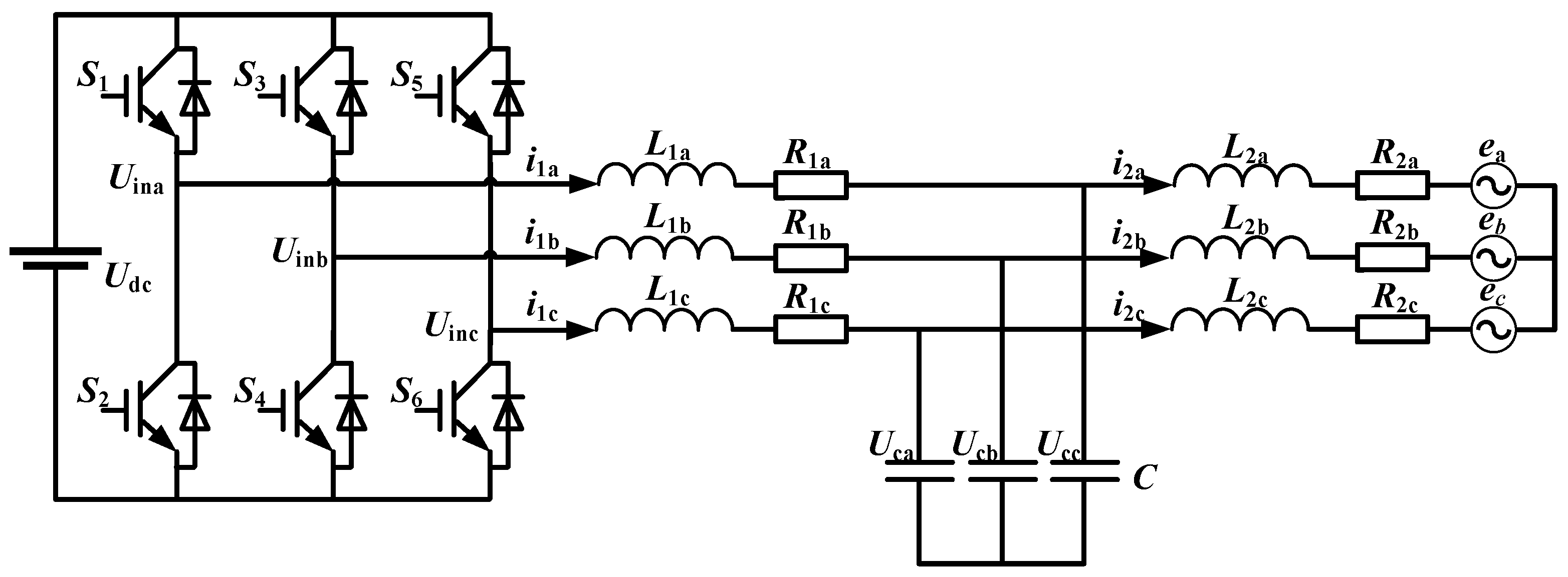
2. Mathematical Model of LCL Grid-Connected Inverter
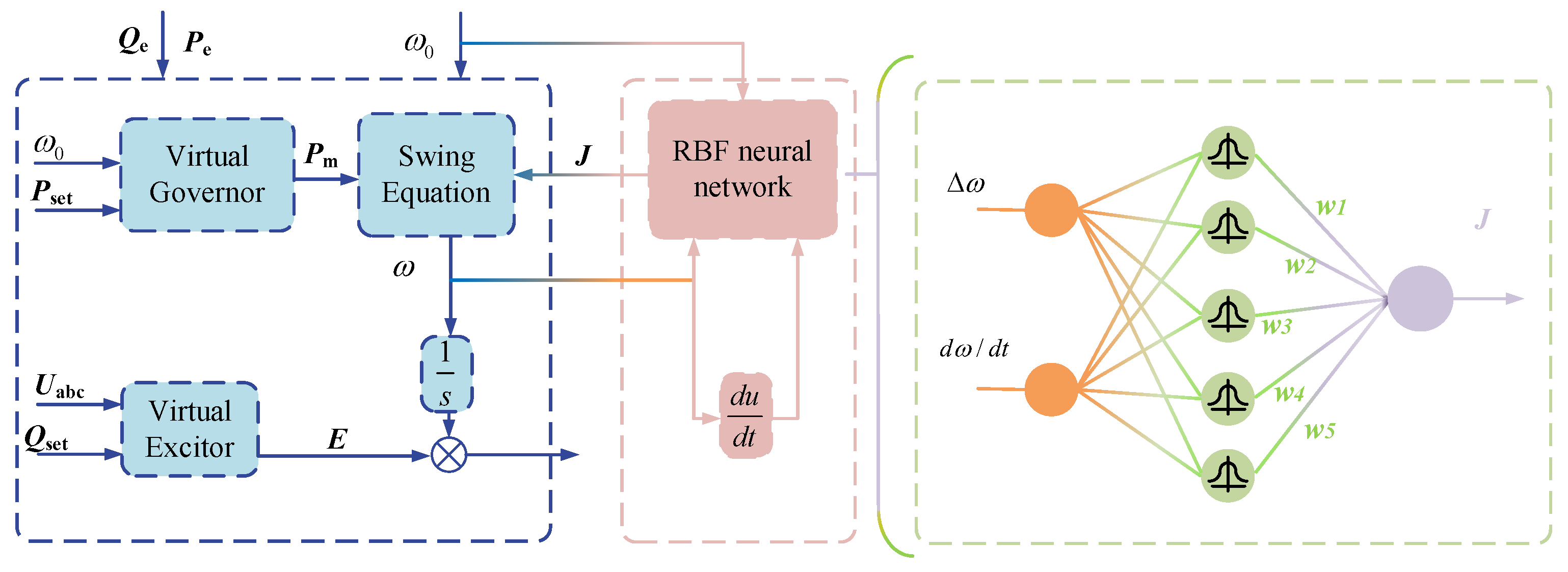
3. Principle and Design of RBF Adaptive Virtual Synchronous Generator
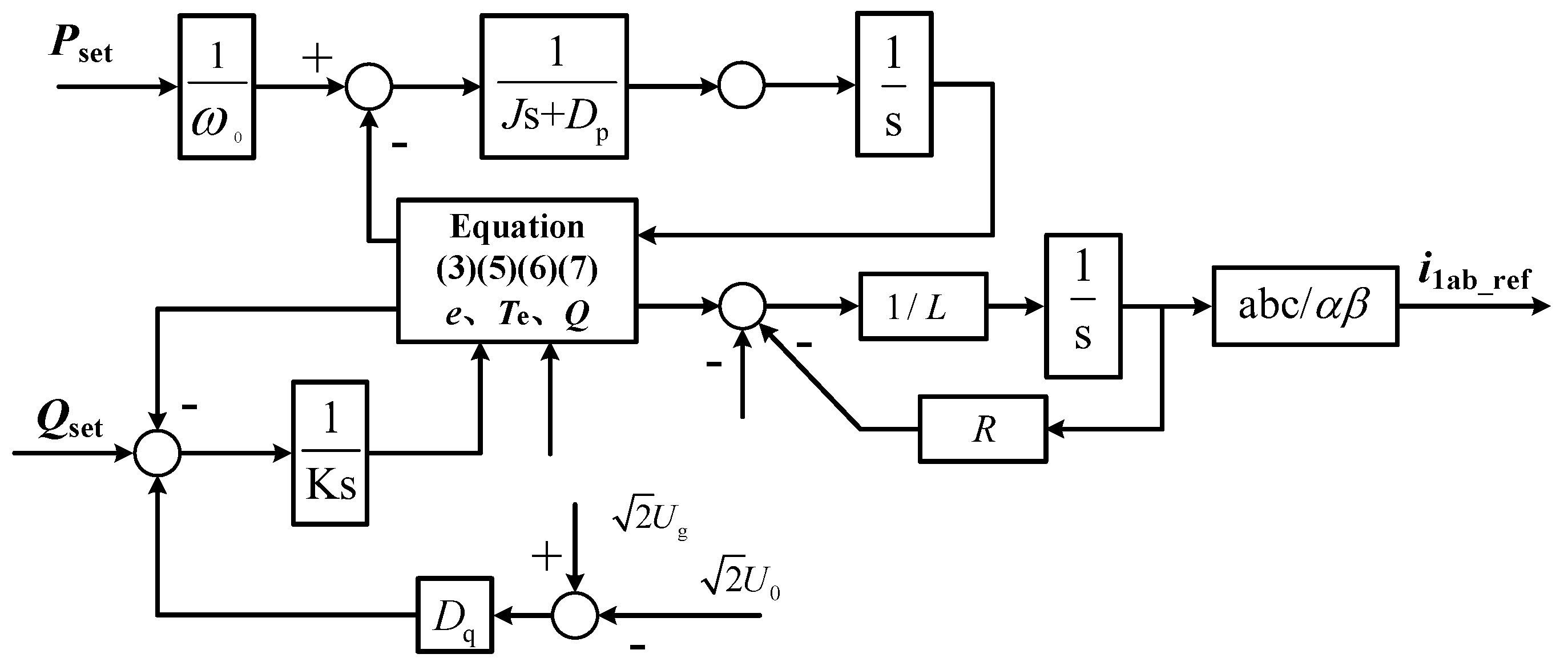
3.1. The Basic Principle of Virtual Synchronous Generator
3.2. RBF Neural Network
3.3. The Establishment and Analysis of Adaptive Model
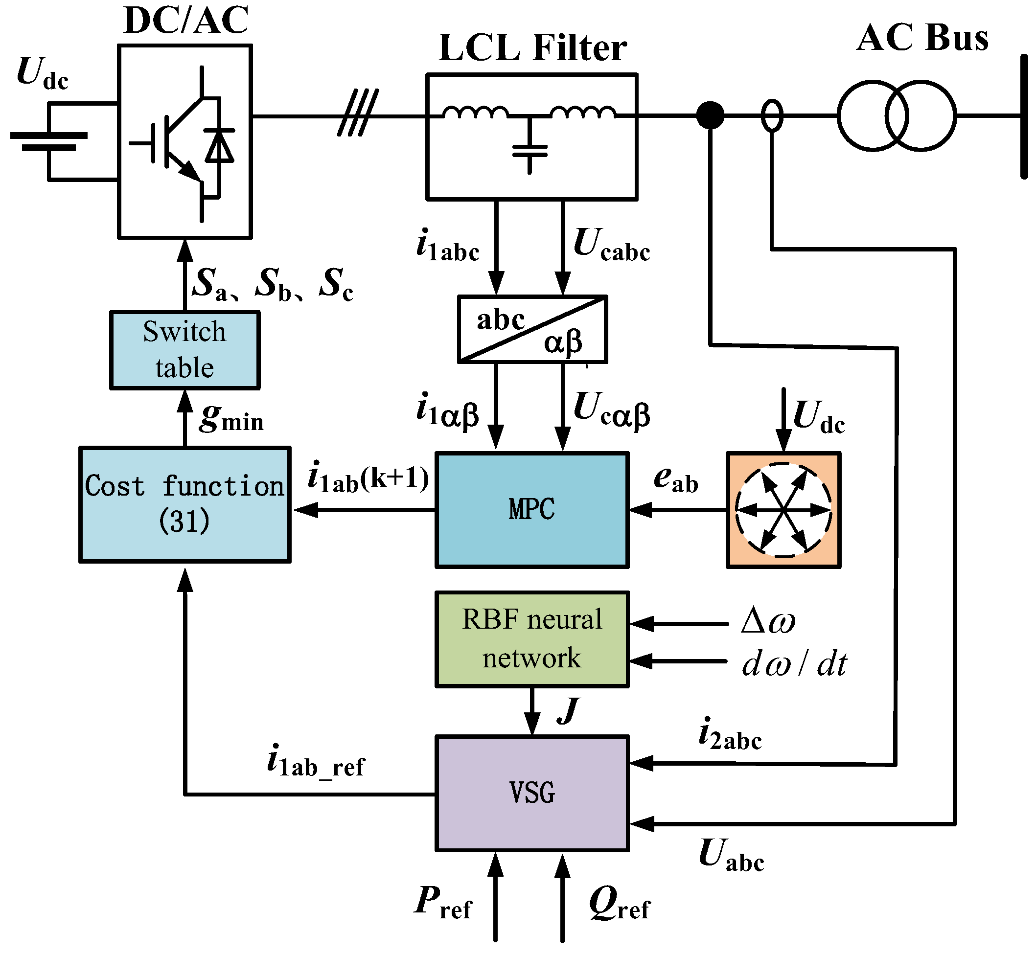
4. Proposed Control Strategy
4.1. Model Predictive Current Control Algorithm
4.2. Topology
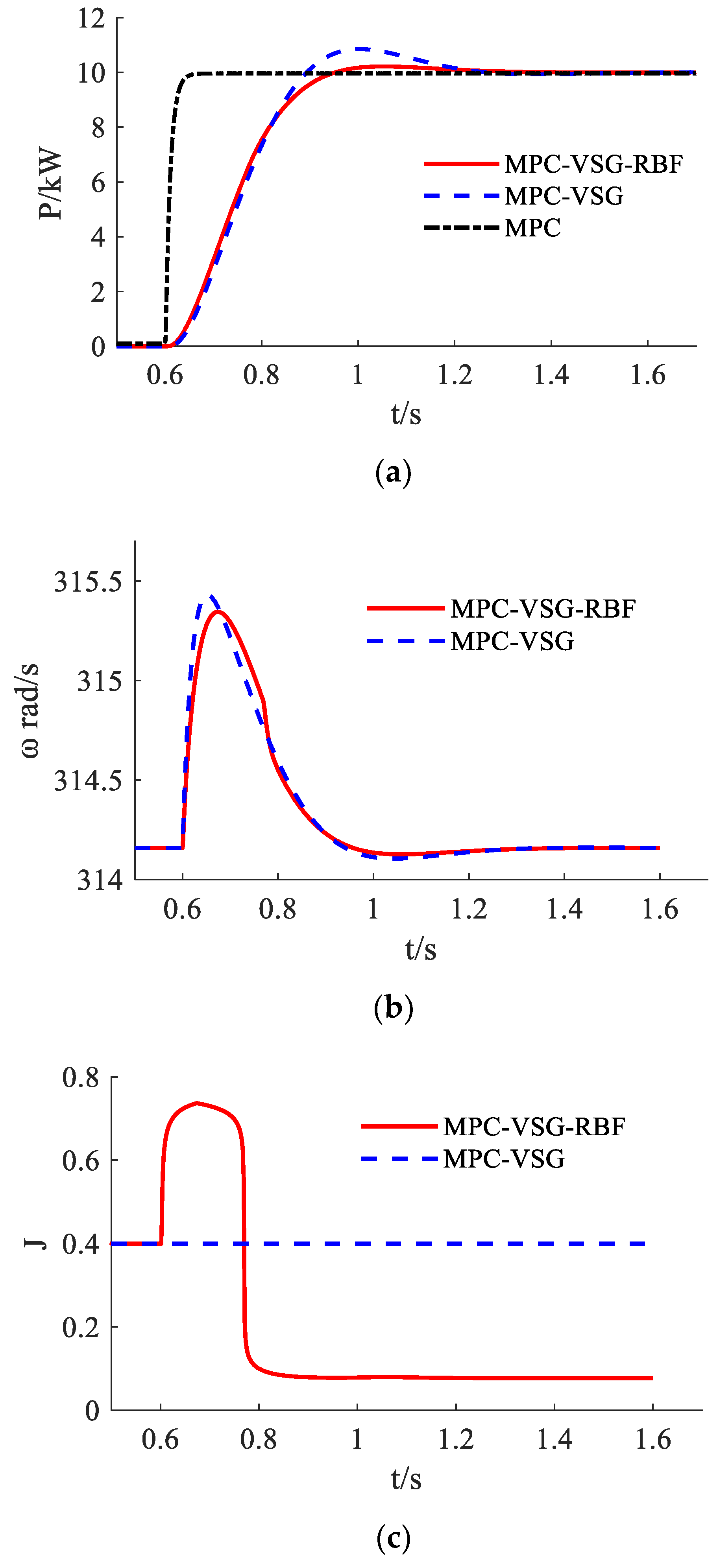
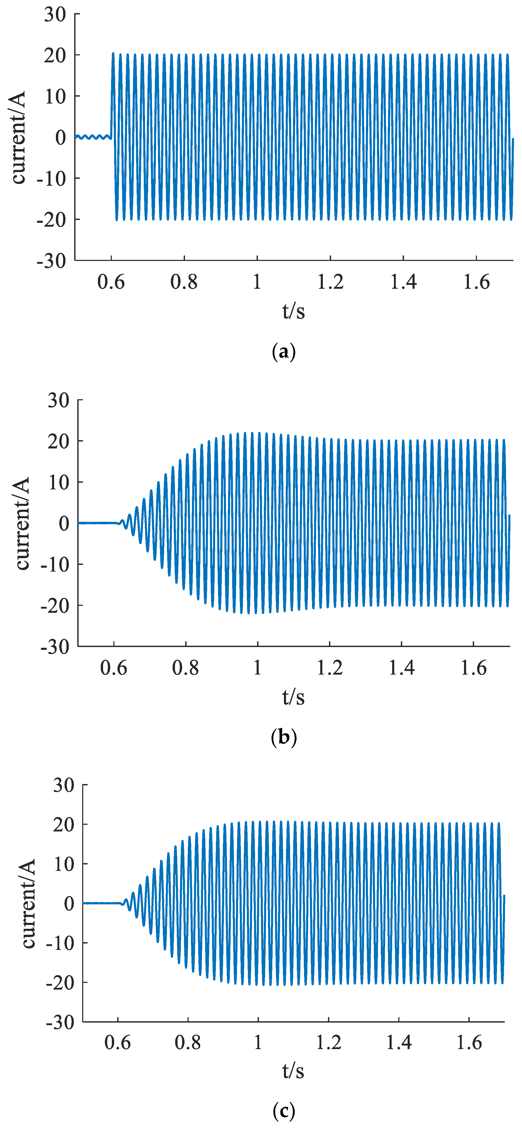
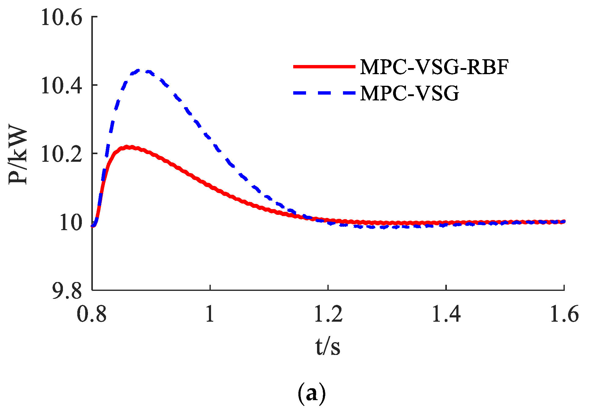
5. Results
6. Conclusions
- (1)
- A VSG is introduced into the model predictive control algorithm. The advantages of the two are effectively combined, which not only reduces the parameter setting, but also provides certain inertial support for the power grid;
- (2)
- Based on VSG control, optimization control of RBF virtual moment of inertia adaptive adjustment is proposed. It effectively solves the power fluctuation and overcurrent problems of traditional VSG control in the transient process, and improves the active power and frequency stability of independent micro-grid;
- (3)
- The traditional MPC control strategy is compared with the proposed MPC-VSG-RBF control method of simulation. The control strategy applied in this paper can improve the inertial response capability of the independent micro-grid and optimize the transient process of the system when the power of the grid is abrupt.
Author Contributions
Funding
Data Availability Statement
Conflicts of Interest
References
- Elmouatamid, A.; Ouladsine, R.; Bakhouya, M.; Kamoun, N.E.; Khaidar, M.; Zine-Dine, K. Review of Control and Energy Management Approaches in Micro-Grid Systems. Energies 2020, 14, 168. [Google Scholar] [CrossRef]
- Nazir, M.I.; Hussain, I.; Ahmad, A.; Khan, I.; Mallik, A. System Modeling and Reliability Assessment of Microgrids: A Review. Sustainability 2022, 14, 126. [Google Scholar] [CrossRef]
- Morovati, S.; Zhang, Y.C.; Djouadi, S.M.; Tomsovic, K.; Wintenberg, A.; Olama, M. Robust Output Feedback Control Design for Inertia Emulation by Wind Turbine Generators. IEEE Trans. Power Syst. 2021, 36, 5056–5067. [Google Scholar] [CrossRef]
- Hong, Q.T.; Ji, L.; Blair, S.M.; Tzelepis, D.; Karimi, M.; Terzija, V.; Booth, C.D. A New Load Shedding Scheme with Consideration of Distributed Energy Resources’ Active Power Ramping Capability. IEEE Trans. Power Syst. 2022, 37, 81–93. [Google Scholar] [CrossRef]
- Aljafari, B.; Vasantharaj, S.; Indragandhi, V.; Vaibhav, R. Optimization of DC, AC, and Hybrid AC/DC Microgrid-Based IoT Systems: A Review. Energies 2022, 15, 6813. [Google Scholar] [CrossRef]
- Villalón, A.; Rivera, M.; Salgueiro, Y.; Muoz, J.; Dragievi, T.; Blaabjerg, F. Predictive Control for Microgrid Applications: A Review Study. Energies 2020, 13, 2454. [Google Scholar] [CrossRef]
- Walz, S.; Liserre, M. Hysteresis Model Predictive Current Control for PMSM with LC Filter Considering Different Error Shapes. IEEE Open J. Power Electron. 2020, 1, 190–197. [Google Scholar] [CrossRef]
- Saeed, M.; Song, W.; Yu, B.; Wu, X. Low-Complexity Deadbeat Model Predictive Current Control with Duty Ratio for five-phase PMSM Drives. IEEE Trans. Power Electron. 2020, 35, 12085–12099. [Google Scholar] [CrossRef]
- Güler, N.; Biricik, S.; Bayhan, S.; Komurcugil, H. Model Predictive Control of DC-DC SEPIC Converters with Auto-tuning Weighting Factor. IEEE Trans. Ind. Electron. 2020, 68, 9433–9443. [Google Scholar] [CrossRef]
- Shetgaonkar, A.; Lekic, A.; Torres, J.L.R.; Palensky, P. Microsecond Enhanced Indirect Model Predictive Control for Dynamic Power Management in MMC Units. Energies 2021, 14, 3318. [Google Scholar] [CrossRef]
- Zhou, D.; Quan, Z.; Li, Y. Hybrid Model Predictive Control of ANPC Converters with Decoupled Low-Frequency and High-Frequency Cells. IEEE Trans. Power Electron. 2020, 35, 8569–8580. [Google Scholar] [CrossRef]
- Guo, X.; Xiao, M.; Gao, Y.E.; Wang, Q.; Wan, Y. Fix-frequency robust power model predictive control method for three-phase PWM rectifiers under unbalanced grid conditions. J. Power Electron. 2020, 20, 1283–1294. [Google Scholar] [CrossRef]
- Zhou, D.; Ding, L.; Li, Y.W. Two-Stage Optimization-Based Model Predictive Control of 5L-ANPC Converter-Fed PMSM Drives. IEEE Trans. Ind. Electron. 2020, 68, 3739–3749. [Google Scholar] [CrossRef]
- Du, W.; Fu, Q.; Wang, H. Power system small-signal angular stability affected by virtual synchronous generators. IEEE Trans. Power Syst. 2019, 34, 3209–3219. [Google Scholar] [CrossRef]
- Chen, M.; Zhou, D.; Blaabjerg, F. Modelling, Implementation, and Assessment of Virtual Synchronous Generator in Power Systems. J. Mod. Power Syst. Clean Energy 2020, 8, 399–411. [Google Scholar] [CrossRef]
- Wu, W.H.; Chen, Y.D.; Zhou, L.M.; Luo, A.; Zhou, X.P.; He, Z.X.; Yang, L.; Xie, Z.W.; Liu, J.M.; Zhang, M.M. Sequence Impedance Modeling and Stability Comparative Analysis of Voltage-Controlled VSGs and Current-Controlled VSGs. IEEE Trans. Ind. Electron. 2019, 66, 6460–6472. [Google Scholar] [CrossRef]
- Du, W.J.; Dong, W.K.; Wang, Y.; Wang, H.F. Small-Disturbance Stability of a Wind Farm with Virtual Synchronous Generators under the Condition of Weak Grid Connection. IEEE Trans. Power Syst. 2021, 36, 5500–5511. [Google Scholar] [CrossRef]
- Zhang, X.Y.; Liu, H.Z.; Fu, Y.; Li, Y.G. Virtual Shaft Control of DFIG-Based Wind Turbines for Power Oscillation Suppression. IEEE Trans. Sustain. Energy 2022, 13, 2316–2330. [Google Scholar] [CrossRef]
- Hou, X.C.; Sun, Y.; Zhang, X.; Lu, J.H.; Wang, P.; Guerrero, J.M. Improvement of Frequency Regulation in VSG-Based AC Microgrid via Adaptive Virtual Inertia. IEEE Trans. Power Electron. 2020, 35, 1589–1602. [Google Scholar] [CrossRef]
- Ren, M.W.; Li, T.; Shi, K.; Xu, P.F.; Sun, Y.X. Coordinated Control Strategy of Virtual Synchronous Generator Based on Adaptive Moment of Inertia and Virtual Impedance. IEEE J. Emerg. Sel. Top. Circuits Syst. 2021, 11, 99–110. [Google Scholar] [CrossRef]
- Li, J.; Wen, B.; Wang, H. Adaptive Virtual Inertia Control Strategy of VSG for Micro-Grid Based on Improved Bang-Bang Control Strategy. IEEE Access 2019, 7, 39509–39514. [Google Scholar] [CrossRef]
- Fu, S.Q.; Sun, Y.; Li, L.; Liu, Z.J.; Han, H.; Su, M. Power Oscillation Suppression in Multi-VSG Grid by Adaptive Virtual Impedance Control. IEEE Syst. J. 2022, 16, 4744–4755. [Google Scholar] [CrossRef]
- Gao, Z.X.; Zhao, J.B.; Yang, X.H.; Yao, F.J.; Fang, J.F. RBF-Based Adaptive Control Strategy of Rotational Inertia and Damping Coefficient for VSG. Electr. Power Constr. 2022, 43, 132–139. [Google Scholar]
- Yang, X.H.; Yao, F.J.; Hao, P.F.; Lu, H. Adaptive inertia control for VSG based on improved RBF neural network. Electr. Meas. Instrum. 2021, 58, 112–117. [Google Scholar]
- Ren, L.T.; Guo, H.; Dou, Z.L.; Wang, F.; Zhang, L.J. Modeling and Analysis of the Harmonic Interaction between Grid-Connected Inverter Clusters and the Utility Grid. Energies 2022, 15, 3490. [Google Scholar] [CrossRef]
- Chen, L.; Tang, J.G.; Dong, H.; Hu, R.Z.; Wang, X.C.; Chen, H.K.; Islam, M.R.; Deng, X.Y. Study of Resistive Superconducting Fault Current Limiters for Stability Improvement of VSG-Controlled Multiple Microgrid Clusters. IEEE Trans. Appl. Supercond. 2022, 32, 5600907. [Google Scholar] [CrossRef]


| Sa | Sb | Sc | Uinα | Uinβ |
|---|---|---|---|---|
| −1/3 Udc | /3 Udc | |||
| −1/3 Udc | /3 Udc | |||
| −2/3 Udc | ||||
| 2/3 Udc | ||||
| 1/3 Udc | /3 Udc | |||
| 1/3 Udc | /3 Udc | |||
| Definition | Value | Definition | Value |
|---|---|---|---|
| Converter input voltage Udc | 700 V | Power grid frequency fg | 50 Hz |
| Output power P | 10 kW | Power grid voltage Ug | 380 V |
| Filter inductor L1 | 5 mH | Inertia J | 0.4 Kg·m2 |
| Filter resistor R1 | 1 Ω | Damping coefficient Dp | 22.1 |
| Filter capacitance C | 3 µF | Reactive power ring Dq | 1605 |
| Filter inductor L2 | 5 mH | Reactive power ring K | 19.8 |
| Filter resistor R2 | 1 Ω |
| Control | MPC-VSG | MPC-VSG-RBF- | ||
|---|---|---|---|---|
| Indicator | ||||
| active power increases | Overshoot of P | 380 W | 220 W | |
| Settling time of P | 0.675 s | 0.6 s | ||
| Overshoot of ω | 0.2 rad/s | 0.1 rad/s | ||
| grid frequency disturbance | Overshoot of P | 440 W | 220 W | |
| Settling time of P | 0.55 s | 0.46 s | ||
| Overshoot of ω | 0.06 rad/s | 0.03 rad/s | ||
Publisher’s Note: MDPI stays neutral with regard to jurisdictional claims in published maps and institutional affiliations. |
© 2022 by the authors. Licensee MDPI, Basel, Switzerland. This article is an open access article distributed under the terms and conditions of the Creative Commons Attribution (CC BY) license (https://creativecommons.org/licenses/by/4.0/).
Share and Cite
Yang, X.; Li, H.; Jia, W.; Liu, Z.; Pan, Y.; Qian, F. Adaptive Virtual Synchronous Generator Based on Model Predictive Control with Improved Frequency Stability. Energies 2022, 15, 8385. https://doi.org/10.3390/en15228385
Yang X, Li H, Jia W, Liu Z, Pan Y, Qian F. Adaptive Virtual Synchronous Generator Based on Model Predictive Control with Improved Frequency Stability. Energies. 2022; 15(22):8385. https://doi.org/10.3390/en15228385
Chicago/Turabian StyleYang, Xuhong, Hui Li, Wei Jia, Zhongxin Liu, Yu Pan, and Fengwei Qian. 2022. "Adaptive Virtual Synchronous Generator Based on Model Predictive Control with Improved Frequency Stability" Energies 15, no. 22: 8385. https://doi.org/10.3390/en15228385