Article

Modern Methods of Strengthening and Sealing Salt Mines

by
Andrzej Gonet
1,*,
Stanisław Stryczek
1 and
Marcin Kremieniewski
2
1
Faculty of Drilling, Oil and Gas, AGH University of Science and Technology, Al. Mickiewicza 30, 30-059 Cracow, Poland
2
Oil and Gas Institute—National Research Institute, 25A Lubicz Str., 31-503 Cracow, Poland
*
Author to whom correspondence should be addressed.
Energies 2022, 15(14), 5303; https://doi.org/10.3390/en15145303
Submission received: 14 June 2022 / Revised: 12 July 2022 / Accepted: 20 July 2022 / Published: 21 July 2022
(This article belongs to the Special Issue Latest Technologies and Tools in Drilling Systems)

Abstract

:
In order to ensure safe working conditions for miners underground, many works are carried out in mines to strengthen and seal mining excavations. This article presents the successfully applied technology for removing water inflow from the unique Salt Mine. Failure to take such action may ultimately lead to the flooding of the “Wieliczka” Salt Mine (KSW). On the basis of the authors’ research studies, some of the implemented works at the “Wieliczka” Salt Mine are presented, the purpose of which is to better protect the mine against the risk of flooding with water. Thanks to this, the mine can safely survive for many more years. This article presents two innovative technologies in salt mines: (1) sealing of the rock mass surrounding the Kościuszko shaft casing in the “Wieliczka” Salt Mine, where jet injection was used as the basic method of making an anti-filter screen outside the shaft casing and classic injection as a supplementary method for sealing the anthropogenic embankment; (2) reconstruction of the internal pillar of safety by implementing a patented technology called “pipeline injection” on the example of the Mina cross-section, in which a catastrophic water inflow was previously created that threatened the existence of the “Wieliczka” Salt Mine. The first method consists of making an anti-filter screen, which is located outside the shaft housing. Unfortunately, it is not possible to perform injection works from inside the shaft housing, because the Kosciuszko shaft, as a ventilation shaft, must be open constantly. To solve this problem, it is designed as the main technology known as jet grouting, which is supplemented by pressure injection at a depth of up to several meters with continuous monitoring of the condition of the casing during injection works. The second example concerns the reconstruction of the internal pillar of mine safety in the area of the northern border of the salt deposit. In this case, the catastrophic hazard is documented, as evidenced by the inflow to the Mina transverse, which is located on the fourth level of the mine. This task was successfully completed by the implementation of a patented technological solution called pipeline injection, the details of which are discussed in this article.

1. Introduction

Globally, mines from which various types of raw materials are extracted are most often closed after the end of their operation. This process is technically, technologically and economically demanding. However, not every mine follows this route, because some of them, due to their geological, technical and artistic values, are protected for future generations as very interesting museum objects. One such mine is the “Wieliczka” Salt Mine, which, thanks to its unique values, was entered on the 1st UNESCO World Cultural and Natural Heritage List in 1978 [1,2]. The Wieliczka salt deposit was created in the Neogene and was beautifully developed as a result of intense geological processes [3,4,5]. It was operated from the 13th century to 1996. As a result of more than seven centuries of mining activity, the mine has 9 main levels, more than 220 km of galleries called transverse and longitudinal beams, and over 6.5 million m³ of chambers in which you can admire beautiful sculptures and bas-reliefs made of salt. Currently, the mine focuses on tourism, sanatorium and educational activities. A significantly simplified diagram of the mining excavations and KSW shafts is shown in Figure 1.
In order to achieve the above goals, it is necessary to carry out specialized security works, the main goal of which is to limit the water inflow to the mine by tight reconstruction of the internal safety pillar, as well as improving the stability of mining excavations [6]. The inflow of water to salt mines can pose a catastrophic threat to them. This is why it is so important to monitor and carry out works securing the mines [6,7]. On the basis of the scientific and research studies of the authors, this publication presents the implemented, selected works at the “Wieliczka” Salt Mine, aimed at saving the mine from flooding and securing it in such a way that it will be possible to admire it for many years to come [8].
Due to the imprecise identification of geological and hydrogeological conditions in the earlier stages, errors related to the exploitation of salt were not avoided. In many cases, they led to disastrous inflows of water along with clay and sand [6,8] surrounding the salt deposit. Such breach of the surrounding clay-gypsum cover with mining excavations led to leakages in some places of the mine. One such tributary was the inflow to the Mina transverse (Figure 2) located on the 4th level of the mine and at a depth of approximately 170 m, which began on 13 April 1992 and caused many problems for both the mine and the city of Wieliczka [1,5].

2. Water Inflow through the Mine Workings Reaching the Ground Surface

Most often, water from precipitation and underground tributaries enters the mines through leaks. They occur at the contact of the rock mass with the shaft casings, which are necessary for the proper operation of the mine, or with filling holes [8,9], which are used to fill selected mine workings with sand. One such facility was the Kosciuszko shaft, which is very important for the mine. It acts as a ventilation and exhaust shaft. The Kosciuszko shaft was built in the 18th century. Currently, its depth is 324 m, and it has a wall, barrel lining at the length from the core to a depth of 62.0 m, and a circular lining along the remaining length of the shaft pipe. The geological conditions around the Kosciuszko Shaft were determined on the basis of geological and engineering studies [10]. Such works are performed prior to the commencement of drilling works and on the basis of profiling of the core holes drilled from the shaft cellar in the axis of the anti-filtration partition (Table 1). The main argument in favor of choosing this shaft for the description in this article is the implementation of jet grouting technology. Additionally, this method is supplemented by a pressure injection [11,12] to seal and strengthen the near-surface area of the casing with the use of a specially developed system for monitoring the casing’s behavior during injection works.
From a depth of 12.5 m to a depth of 45 m, there are deposits of clay and gypsum, which were not waterlogged. Two water horizons are distinguished in the analyzed geological profile of the shaft. The first occurs in the depth range from 1.6 to 4.6 m in the embankment formations mixed with Quaternary silts and sand, and stabilizes at a depth of 1.6 to 3.0 m. The second aquifer in the Quaternary formations is drilled at a depth of approximately 8.0 m below the ground level, i.e., on the border of the dust ceiling. The water level in these formations stabilizes on the ground surface. This horizon is infiltrated with Quaternary deposits. The waterlogged soil facie in this horizon is highly susceptible to liquefaction. The water flowing into the shaft are sodium-chloride brines with mineralization ranging from 27 to approximately 300 g/dm3. The mineralization of the upper two horizons ranges from 27 to 50 g/dm3. Mineralization of leakages from the salt deposit or from technical water, occurring in the vicinity of the inlets and accumulating in the sump, reaches approximately 300 g/dm3. All water leaks are characterized by a high content of SO4 ions, ranging from approximately 0.7 to 4.7 g/dm3, which makes them strongly sulphate aggressive towards cement. Sometimes there is aggressive CO2 in the water, and the pH of the water ranges from 7.0 to 7.8. Due to the strong sulphate and carbonic acid aggressiveness of the water, surface and structural protection of concrete structures made in the shaft is required, as well as the appropriate selection of a cement slurry that can be used in injection holes. The inability to turn off the shaft makes it impossible to seal its housing from the inside. Therefore, it was decided to design an anti-filter screen outside the shaft housing, the task of which was to minimize the water inflow to the shaft.

2.1. Drilling Holes and Injection Technology

After a comprehensive analysis of geological and engineering, hydrogeological and technical conditions, it was decided that drilling and injection works would be best carried out from the level of the shaft cellar. In this case, the distances of the openings from the shaft housing are significantly reduced, and at the same time the number of openings necessary to form the anti-filter screen is reduced in relation to the design of openings around the shaft headroom building. The disadvantage of such a solution is a significant limitation resulting from the height of the shaft cellar room, which is 2.20 m, and the mine infrastructure existing there. However, when selecting the injection technology, the assumed purpose of the works, geological, hydrogeological and technical conditions as well as the safety of the shaft support, the structure of which cannot be damaged during sealing works, are taken into account. Therefore, in order to seal the Kosciuszko shaft, the main method is jet grouting [13,14,15], and the complementary method of pressure injection [16,17]. Due to the very large variation in the lithological surroundings of the shaft lining, it was decided that out of 88 holes, 4 would be core drilled. This action facilitates making decisions regarding the selection of cement slurry recipes and parameters of the injection technology [14]. The injection holes are designed as vertical holes [13] close to the outer shaft housing. The length of the holes depends on the drilled ceiling of the water-impermeable layer and the applied insulation overlap. Drilling and injection works are carried out as the so-called first, second and third execution, which guarantees the formation of a tight anti-filtration screen outside the shaft housing. Geopolymeric slurries and a superplasticizer are used for sealing works, thanks to which it significantly improves the rheological properties of the cement slurry and increases its resistance against corrosion. These holes are injected right after they are drilled to the depth of 25.0 m. Subsequent holes are drilled to a depth of 15.0 m and the slurry is injected into the rock mass while pulling the drill string out of the hole. Throughout the screen, first, second and third order holes are distinguished, for which injection parameters are individually selected, i.e., pressure and pumping capacity, rotational speed and lifting speed of the drill string [18,19]. Due to the poor recognition of the strength of the shaft lining and ensuring its safety, the first injection is made at a pressure of 5.0 MPa, and the next injections are made at increasing pressures, which are 15.0, 18.0, 25.0, 27.0 and 30.0 MPa. Only the latter pressure causes the sealing slurry to penetrate into the shaft. Therefore, in 6 consecutive holes, the reduced pressure of slurry pumping to 20.0 MPa is applied. In the next well, an attempt was made to increase the injection pressure of the slurry to 25.0 MPa, which leads to the breakthrough of the slurry into the shaft. After analyzing the data from displacement monitoring, visual monitoring and direct observations, it was decided to use the injection pressure of 20.0 MPa in the next 15 wells. In the next stage of works, after the completion of 32 wells, it was decided to increase the injection pressure to 26.0 MPa. During this time, no significant penetration of the sealing slurry into the shaft was observed. A pressure of 30.0 MPa was applied to the last 31 holes. Other important parameters of injection technology are worth mentioning:
-
Slurry pumping expenditure from 75 to 170 dm3/min.
-
Drill string lifting speed from 0.2 to 0.4 m/min.
-
Drill speed from 22.5 to 125.0 rpm.
-
Number of injection nozzles 2.
-
Diameter of injection nozzles from 2 to 3 mm.
In the course of sealing the glass, in addition to the above-mentioned parameters of the injection technology, the following calculations are made: hydraulic power in the nozzles, dynamic pressure of the slurry, unit energy, unit work and speed of the slurry outflow from the injection nozzles. A comprehensive analysis of geological, hydrogeological and technical conditions as well as analysis of the parameters of the injection technology allows us to refine the appropriate technology for sealing the Kosciuszko shaft lining. The observed initial inflow of water and injection cement slurry to the shaft take place mainly through the places of weakening of the wall lining. They are caused by the construction of anchors, platforms or struts or other elements that violate the continuity of the shaft housing. Subsequent inflow of fluids through cracks or weakening surfaces of the mortar by chemical corrosion are of a secondary nature. An important aspect is that in the course of the works, despite increasing the injection pressure, penetrations of the sealing slurry into the shaft occurred with less and less intensity. This proves the successive sealing of the rock mass through the production of interconnecting injection columns forming an anti-filter screen and indirect strengthening of the rock mass around the shaft. As a result of the performed works protecting the shaft lining, it is estimated that injection columns with a diameter of approximately 400 mm and a total length of 1313 m were created; using 347 m3 of cement slurry. As a result of these works, a tight anti-filter screen was created around the Kosciuszko shaft housing. Pressure injection was applied to all orifices immediately after completion of jet grouting injection. Their length is from 1.5 to 2.5 m, and the injection is carried out through a mechanical packer fastened in the floor of the shaft basement, while maintaining one pressing zone in each of the holes. The injection of the injection slurry takes place at a pressure not greater than 0.3 MPa. The criterion for ending the injection is to maintain the pressure of 0.3 MPa for 30 min, or to compress the volume of the sealing slurry equal to 0.5 m3/meter of the hole. 42.0 m3 of slurry is packed into the above caulking holes.

2.2. System for Monitoring the Sealing Process in the Kosciuszko Shaft

Before the main injection works, a special monitoring system [20] was designed and installed in the shaft, which covered the entire scope of security works. In particular, the shaft casing and the impact of the slurry injection process into the rock mass through the boreholes. The following criteria were established:
(a)
Normal—If the displacement has reached the value of ±0.5 mm/1 m, injection works can still be carried out, but with a reduced output of the pumping pump and the pressure of pumping the slurry not increasing.
(b)
Warning—If the displacement has reached the value of ±1.5 mm/1 m, stop pumping the slurry and observe the displacement in the shaft housing and the pressure on the pressure gauge of the discharge pump. After the technological break and the deformation returns to normal, the injection of the slurry can be repeated, but with a reduced slurry expenditure.
The entire control and measurement system is fully functional in practice and is recommendable for similar works in mining shafts. The place of monitoring of the shaft casing sealing process is also the injection and drilling station. Observations and measurements begin with drilling the hole, which makes it possible to identify the lithological profile and assign it to technological drilling parameters. There is a drilling card for this purpose. The place of monitoring is also the position of the sealing slurry preparation, for which specific recipes are developed. After the individual components of the slurry have been thoroughly mixed with water, control tests should be carried out. The next place of inspection is the slurry pumping station, where the pressure of slurry injection through the holes into the rock mass is recorded. All the recommendations for starting the pressing of the slurry as well as the entire cycle of slurry injection should be precisely followed. A sufficient and decisive condition for discontinuing the injection of slurry into the well is the presence of at least one of the following conditions:
-
Maintenance of the admissible pressure of slurry indicated on the pump for 10 min.
-
Forcing the permissible volume of the slurry into the injection zone.
-
The displacement of the shaft casing, recorded with control and measurement equipment, exceeding the value of ±3.0 mm/1 m, then the injection of the slurry should be stopped immediately and a stand-up position should be ordered, carrying out intensive monitoring and analysis of the situation. Only after returning to the normal state (±0.5 mm/1 m), injection works can be resumed.
A very important element of the entire monitoring is the video observation system for the shaft casing, which shows the image from four cameras simultaneously on the monitor located on the shaft core. The telemetric monitoring system consists of modules for observation in five horizontal sections and one vertical line along the entire length of the monitored fragment of the shaft. In addition, observations of changes in the inclination are carried out using geodetic biaxial inclinometers. During the sealing process of the Kosciuszko Shaft, a very important role is played by the system of measuring changes in length, aimed at determining the linear deformations along the tested direction. The designed system enables the determination of length changes along the main shaft axes in five cross-sections and along the plumb line. The cross-sectional monitoring system, on the other hand, consists of two mutually perpendicular strain gauge bases on each of the selected observation horizons. Monitoring in the vertical profile is carried out in four sections between the measurement horizons. All data are presented in graphical and tabular form. In addition, continuous control of changes in the inclination of the shaft components during injection is carried out, by installing on each measurement horizon precise Nivel 220 inclinometers by Leica. The observation data are transferred to a computerized control system and supplements the monitoring data. From a technological point of view, an important element of the system is the module of automatic notification of persons authorized to inform about exceeding the assumed alerting levels. Notification can be sent electronically and is additionally displayed on the monitor screen.

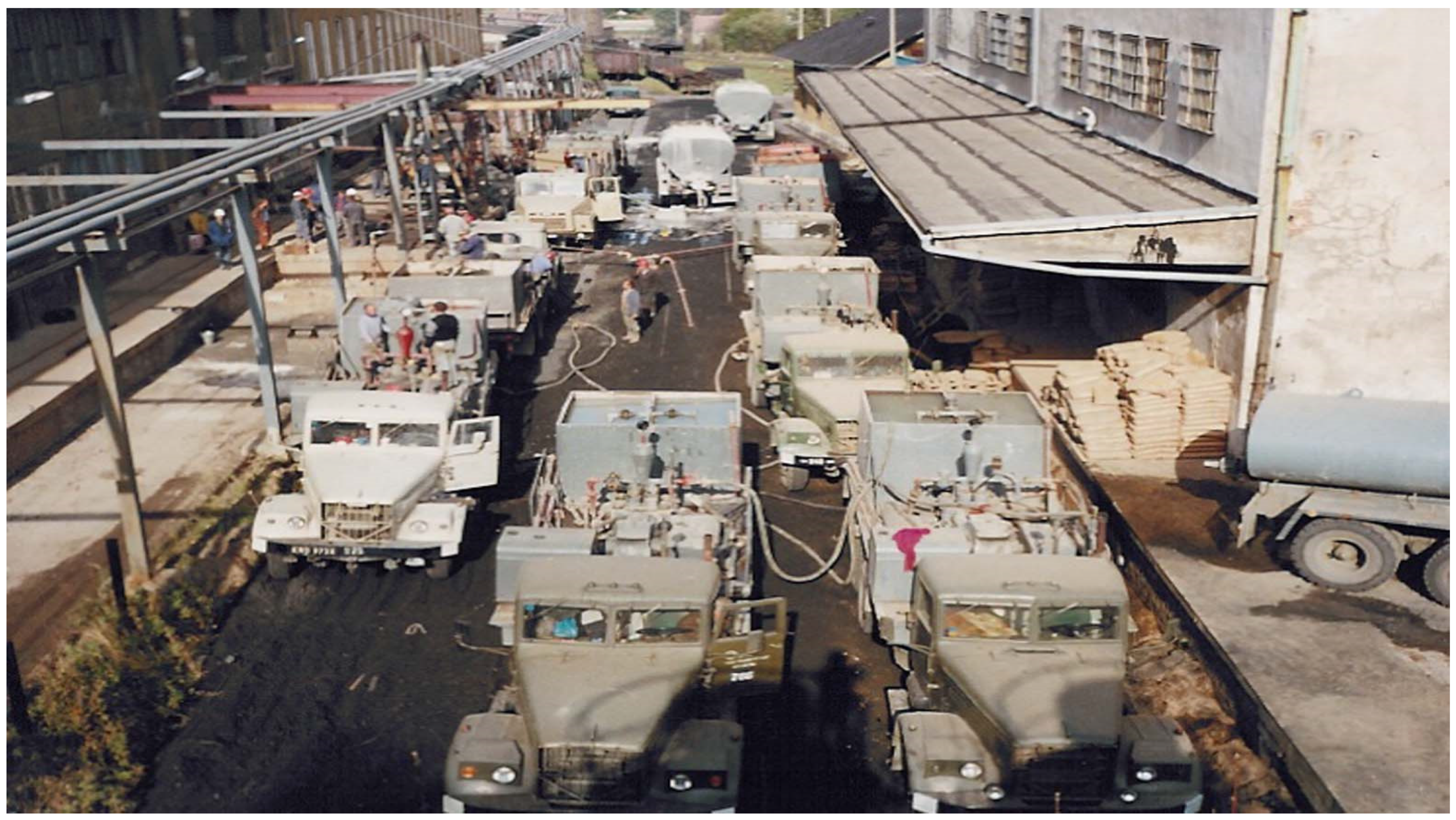
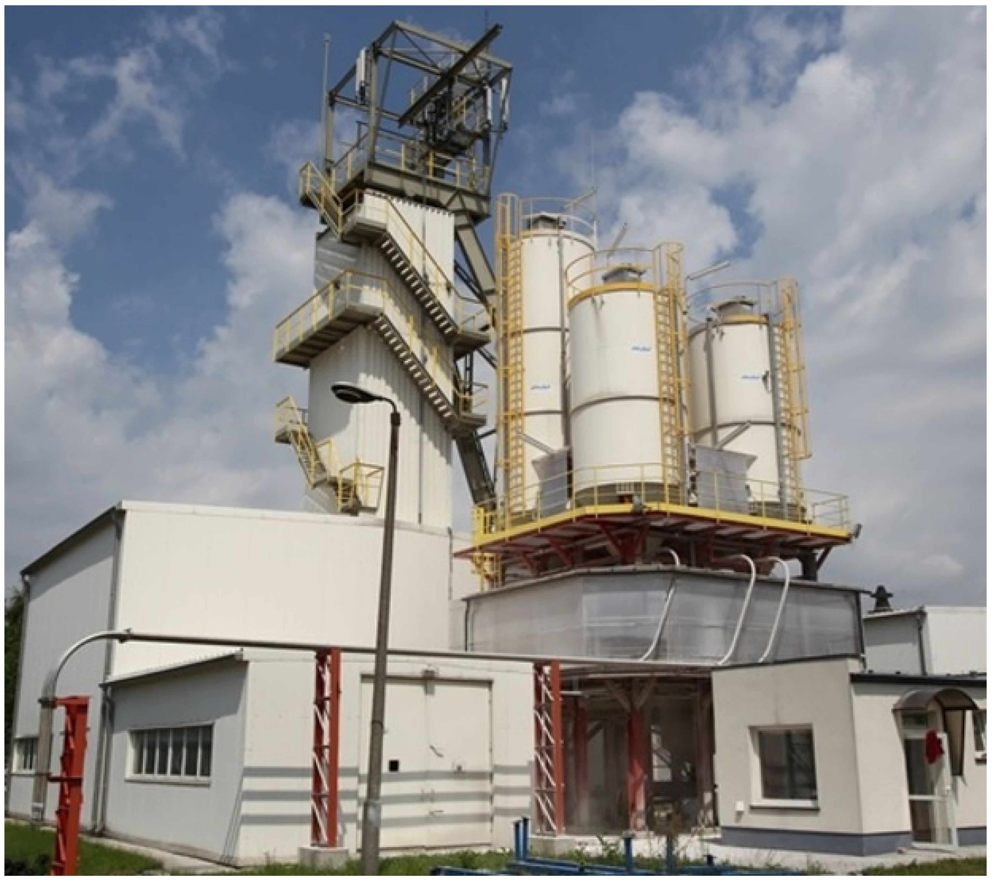
3. Pipeline Injection

Every year, the number of exploited mine workings increases, making it necessary to seal exploited mines worldwide. As a result of many years of experience, various technological solutions have been developed that allow the injection of sealing slurries in order to fill free rock spaces or to eliminate physical discontinuities of the rock mass. The disastrous inflow to the Mina transverse [9], which started on 13 April 1992, significantly contributed to the development of the pipeline injection. The transverse is located on the 4th level of the mine (Figure 2) and at a depth of approximately 170 m. Rescue work [1] covers a wide range; inter alia, drilling two holes from the ground surface, i.e., the hydrogeological R-I (Figure 2) and the research R-II. During the injection of the slurry, hydraulic connectivity was found between the R-II borehole and the Poniatowski cross-sections on level III and the Kunegunda cross-section on the higher level II. This event confirms that the rock mass in the immediate vicinity of the Mina cross-section is of low strength and poses a direct threat to unique objects on a global scale.
The potential inflow of water to these crossbars may pose a direct threat to the tourist route and the facilities located there, and poses a serious threat to the entire “Wieliczka” Salt Mine. In order to save the Wieliczka mine, it was proposed to liquidate the final sections of the Kunegunda and Poniatowski cross-sections [21], located above the Mina cross-section, and thus to rebuild the internal safety pillar [22]. However, then a problem arose regarding the method of their tight liquidation, as only such a procedure could be implemented. The following difficulties were identified in the implementation of the idea in question:
-
How to transport huge amounts of materials (binders, additives, and admixtures) included in the formulas of sealing slurries [23,24,25] to their destination, if there are no rails enabling the transport of materials, the excavations were approximately 4 m2 in diameter, and in some places there were embankments rocks from the ceiling.
-
As in the workings described above, make a continuous large volume of cement slurry.
-
Where to find a place to set up pumps for slurry injection.
-
What are the recipes of the slurries for filling the voids in the transverse ends and how to secure the given section of the transverse section to ensure that the prepared slurry will not spill uncontrolled and will ensure tight filling of the voids to be liquidated.
An original method is the pipeline injection method, which can be implemented in any mine, both during its normal operation and during its transformation into a historic object or even during its decommissioning. The pipeline injection method, with proper design and execution, allows for tight filling of the voids intended for liquidation. This solution has been patented and its owner is the AGH University of Science and Technology Stanisław Staszic in Krakow. This method was first implemented in the “Wieliczka” Salt Mine [14,26]. The currently used constructions of forcing and venting pipelines enable accurate and tight filling of voids in the backfilled mining excavation and make it possible to seal cavities in the roof of the excavation. By analyzing the current level of technical, technological and organizational possibilities and making the economic balance for the project, it can be concluded that the most economical technology is the surface preparation and injection of the sealing slurry.
This technology, compared to the subsurface method, has the following advantages:
-
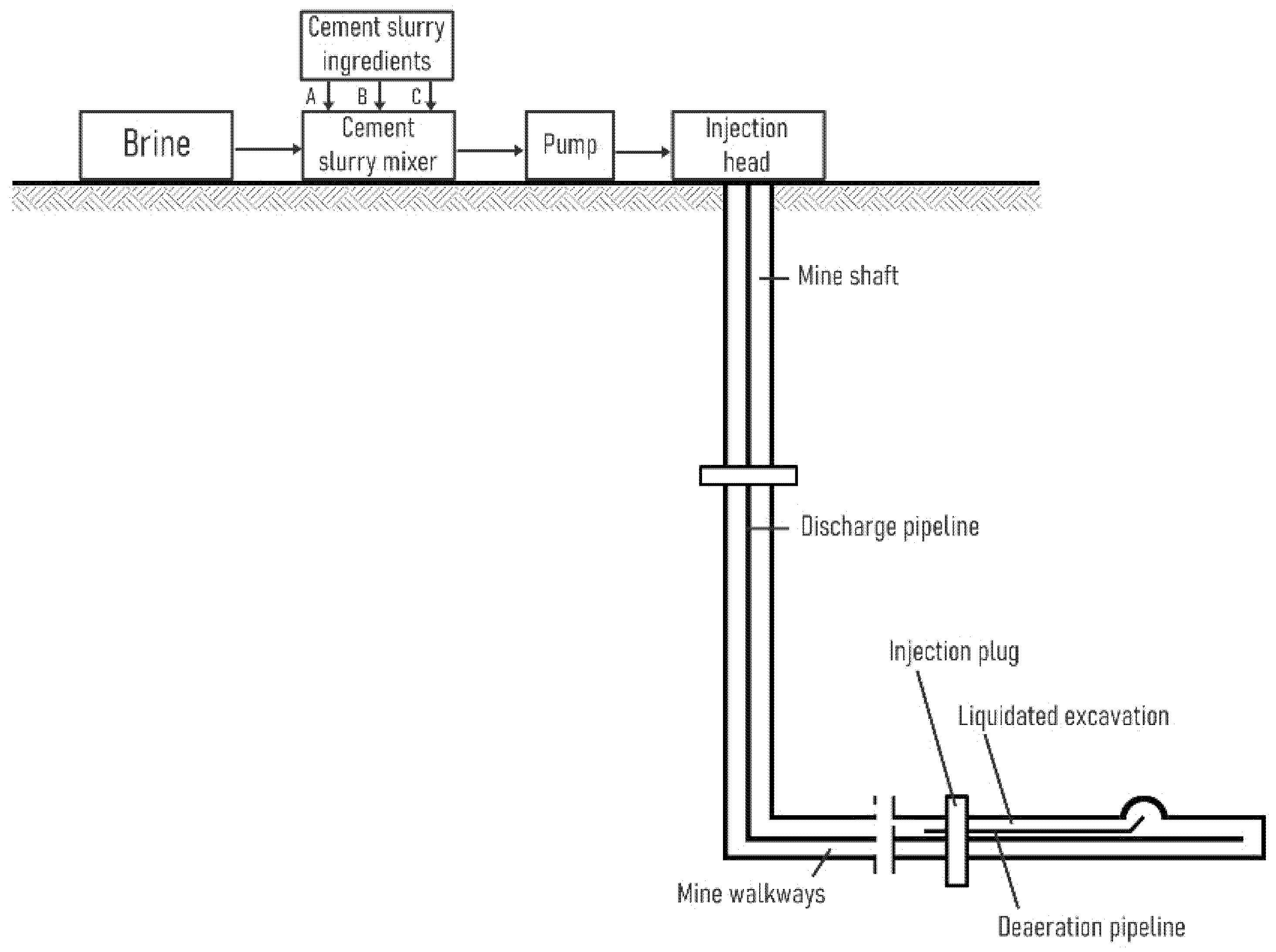
Thanks to the preparation of the sealing slurry on the surface, it is not necessary to transport individual components through the shaft deep into the mine, thus shortening the time of filling the voids in the rock mass.
-
On the surface, there are much more favorable conditions for making the slurry than in mining excavations, because it is possible to fully control and modify the rheological and strength parameters [27,28].
-
Using the technology of surface injection of the sealing slurry, the time of people staying in the area of the filled excavation is reduced to a minimum, which increases work safety.
-
Typical surface equipment can be used to prepare the slurry, which does not have to meet the stringent requirements of mining regulations regarding the use of devices and machines in underground workings.
The main advantage of this technology is the possibility of making the slurry and its injection from the ground surface to the liquidated ends of mining excavations (Figure 3).
In the first attempt to implement a pipeline injection, a discharge pipeline was installed in the Kosciuszko shaft. It connects the pumps and the injection head located on the ground with the end of the discharge pipeline located at the end of the crossbar to be liquidated. The discharge pipeline can be used many times, but after the injection works are completed, the slurry must be effectively flushed with fully saturated brine.
During pipeline injection, it is very important [26,29,30,31]:
-
Having appropriate machines, devices and equipment for the preparation and injection of the slurry into the closed mining excavations.
-
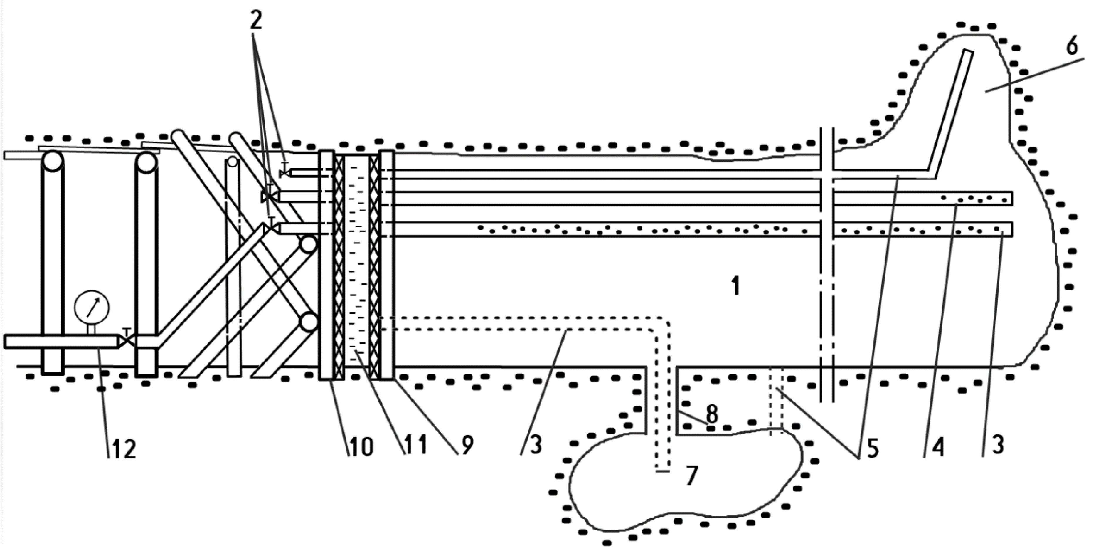
Designing the arrangement of discharge, air-pressure and vent pipelines in the liquidated rock mass space.
-
Control of gate valves, which are mounted on each pipeline in front of the sealing plug.
-
Exercise particular caution when overvoltage of the pipeline supplying the slurry to the liquidated area from the discharge pipeline to the venting and pressure pipeline and, in the final phase, to the deaeration pipeline.
The pipeline injection method allows to tightly fill the voids formed in the roof of the excavation by appropriately covering the pressure and venting pipelines (Figure 4) and to properly make the sealing plug.
In the initial stage of implementation, preparation and injection are carried out with the use of classic devices and accessories used for cementing deep boreholes (Figure 5).
First, the final sections of these cross-sections, which were located in the mine’s hazard zone and in the vicinity of the Mina cross-section, were dismantled. An total of 342 m3 of sealing slurry, prepared in saturated brine, was pumped beyond the injection dam into the Poniatowski cross-section. The Kunegunda transverse, located on the second higher level, was liquidated by filling its final 92 m length with sealing slurry by injecting 458 m3 of slurry. In order to eliminate these cross-sections, original recipes of the cement slurry were developed and implemented [23,32,33,34], prepared on the surface and pressed with previously built-in pipelines in the shaft and selected sidewalks to the ends of the cross-sections to be liquidated. After the pipeline injection had been proven in practice, the “Wieliczka” Salt Mine commissioned the design and construction of a specialized injection node located near the Kościuszko shaft, which was used to transport the slurry in the subsequent stages of injection works (Figure 6).
In the worst geomechanical condition, in the vicinity of the Mina transverse, there was the Badenia transverse (Figure 2), which is located on the 5th level, and in a cave-like condition along with the excavations leading to it. Additionally, this case was dealt with. First, a hole was drilled from the level IV from the Mina transverse, with a location corresponding to the location of the injection plug in the Badenia transverse. Then, the sealing slurry was fed through this opening into the transverse of Badenia in portions of a special recipe with a short setting time in order to make a sealing plug at the fifth level as quickly as possible. In the same way, successive holes were drilled through which the slurry was injected until it appeared at the outlet of the adjacent hole, and according to this principle, the designed section of the transverse was filled with slurry through the holes.

4. Conclusions

1.
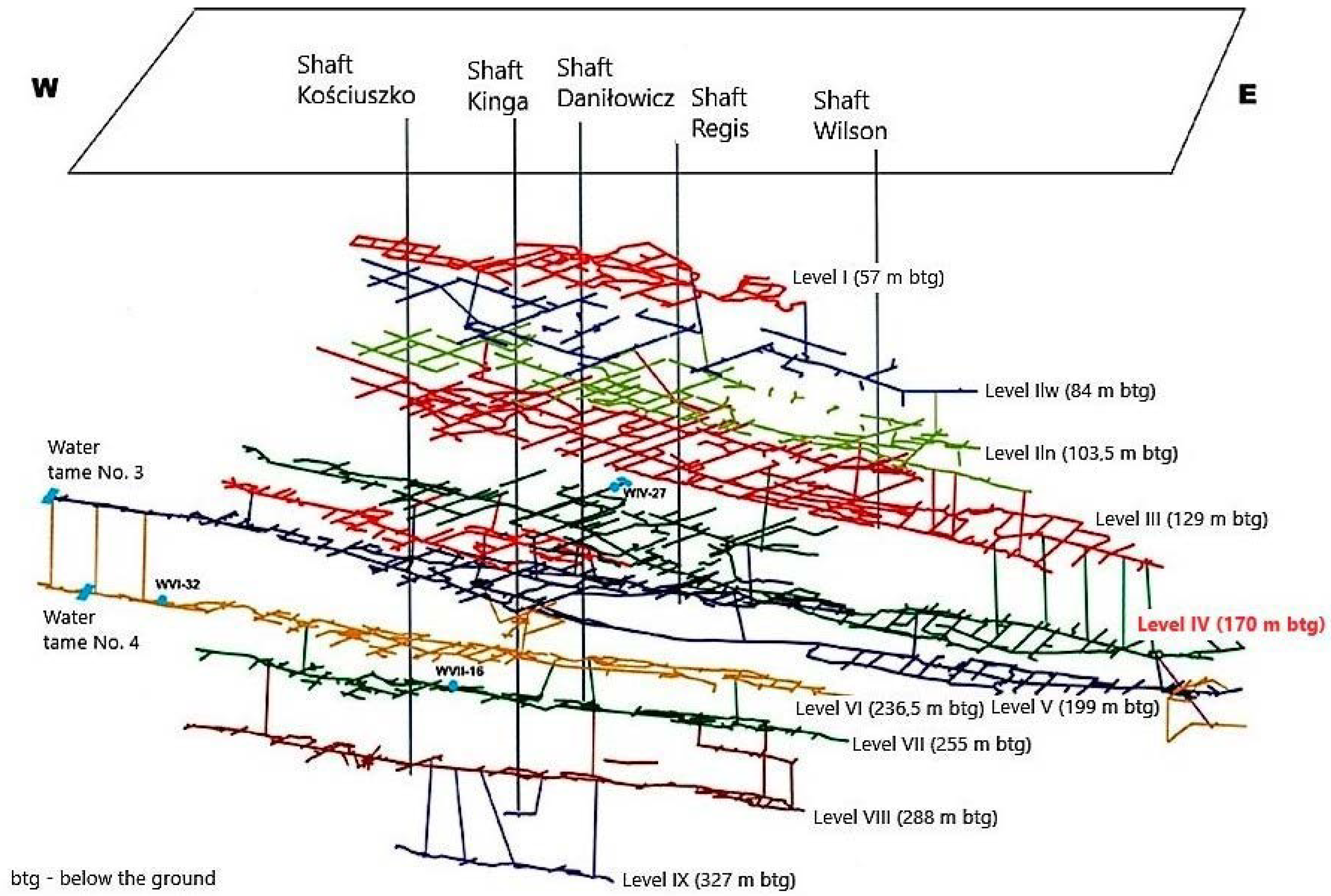
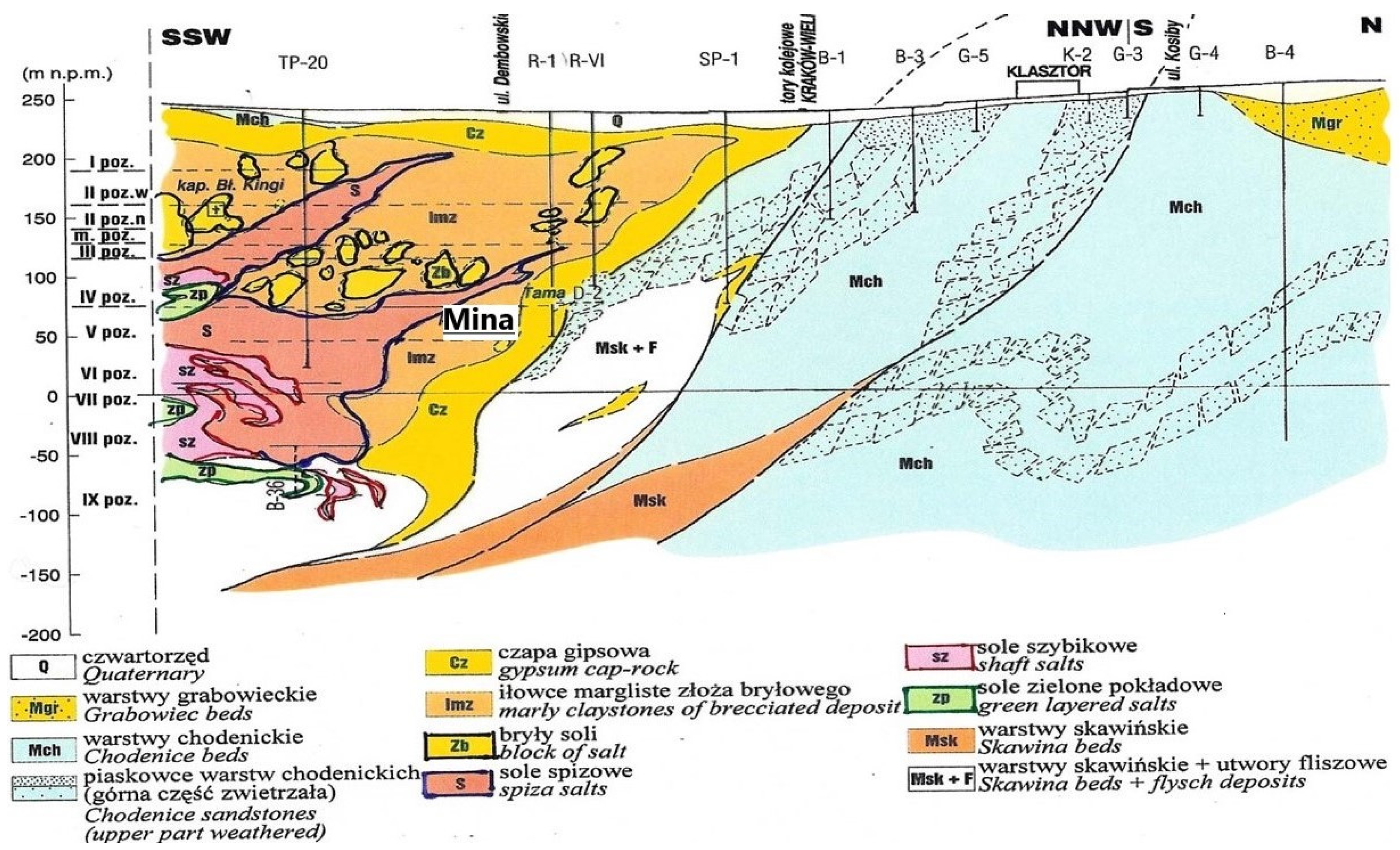
Water inflow is a problem for any mine. It is particularly dangerous if water inflow occurs in salt mines located in unfavorable geological and hydrogeological conditions, additionally with large amounts of water inflow and with a significant share of the solid phase. Such a case took place in the Mina crosshead in the “Wieliczka” Salt Mine.
2.
In order to limit the inflow of water to the Kosciuszko Shaft, a vertical anti-filtration screen was designed in the vicinity of its outer casing. The use of the main jet-grouting method and a supplementary method of pressure injection to seal the subsurface anthropogenic embankment under the floor slab of the shaft basement has proved to be an effective technology.
3.
To ensure the safety of the Kosciuszko shaft casing, a special control and measurement system was designed and installed, which during the injection works signaled one of the three states of the casing: normal, warning or alarm. In the case of the jet grouting technology used to strengthen and seal the shaft lining, it is recommended to monitor displacements and use video monitoring as well as to constantly control changes in the inclination of the shaft components during injection.
4.
The use of the pipeline injection method is recommended for the reconstruction of the internal safety pillar and for tight filling of voids in mines, especially salt.
5.
Pipeline injection technology, compared to other methods of tight filling of voids in mines, is characterized by:
-
Reduced transport time of materials from the ground surface to their final destination, thus shortening the time of filling voids in the rock mass.
-
More favorable conditions for making the slurry on the ground surface than in mining excavations.
-
Shorter time spent by employees in the area of the filled excavation compared to underground methods, which increases work safety.
6.
After eliminating the cross-sections in the northern part of the Wieliczka salt deposit, the conducted gravimetric and microgravimetric studies as well as hydrogeological observations confirmed a significant reconstruction of the northern surroundings of the salt deposit.

Author Contributions

Conceptualization, S.S.; Data curation, A.G.; Formal analysis, S.S. and M.K.; Funding acquisition, A.G.; Investigation, S.S. and M.K.; Methodology, A.G.; Project administration, A.G., S.S. and M.K.; Resources, M.K.; Validation, A.G.; Visualization, M.K.; Writing—original draft, A.G. and S.S.; Writing—review & editing, M.K. All authors have read and agreed to the published version of the manuscript.

Funding

This research was funded by Polish Ministry of Science and Higher Education, grant number 16.16.190.779.

Institutional Review Board Statement

Not applicable.

Informed Consent Statement

Not applicable.

Data Availability Statement

Not applicable.

Conflicts of Interest

The author declares no conflict of interest.

References

  1. Hanik, M.; Klimowski, S. Wieliczka Siedem Wieków Polskiej Soli; Interpress: Warszawa, Poland, 1988. [Google Scholar]
  2. Porzucek, S.; Loj, M.; d’Obyrn, K. Surface Microgravity Monitoring of Underground Water Migration: A Case Study in Wieliczka, Poland. Energies 2022, 15, 4012. [Google Scholar] [CrossRef]
  3. Team under Supervision of Aleksander Garlicki. Studium Możliwości Likwidacji Zagrożenia Wodnego Dla Zabytkowej Kopalni Soli Wieliczka za Pomocą Bariery Drenażowej Lub Ekranu Izolującego; Projekt Badawczy Zamawiany KBN nr PBZ 066-01. Faculty of Geology, Geophysics and Environment Protection, AGH University of Science and Technology: Kraków, Poland, 1995; Unpublished work. [Google Scholar]
  4. Garlicki, A.; Gonet, A.; Stryczek, S. Reinforcement of Saline Rock Mass on the Example of the Salt Mine Wieliczka. Frontiers of Rock Mechanics and Sustainable Development in the 21th Century. In Proceedings of the ISRM International Symposium: Second Asian Rock Mechanics Symposium, Beijng, China, 11–14 September 2001; pp. 581–583. [Google Scholar]
  5. Sun, Y.; Li, G.; Zhang, J.; Qian, D. Stability Control for the Rheological Roadway by a Novel High-Efficiency Jet Grouting Technique in Deep Underground Coal Mines. Sustainability 2019, 11, 6494. [Google Scholar] [CrossRef] [Green Version]
  6. Guan, C.; Yang, Y. Field Study on the Waterstop of the Rodin Jet Pile Method in a Water-Rich Sandy Gravel Stratum. Appl. Sci. 2019, 9, 1709. [Google Scholar] [CrossRef] [Green Version]
  7. Cao, C.; Shi, C.; Lei, M. A Simplified Approach to Design Jet-Grouted Bottom Sealing Barriers for Deep Excavations in Deep Aquifers. Appl. Sci. 2019, 9, 2307. [Google Scholar] [CrossRef] [Green Version]
  8. Gonet, A.; Stryczek, S. Projekt Techniczno-Technologiczny Wzmocnienia Górotworu w Otoczeniu Poprzeczni Mina Pomiędzy Tamą Wodną a Tamą T-4. Faculty of Drilling, Oil and Gas, AGH University of Science and Technology: Kraków, Poland, 1993; Unpublished work. [Google Scholar]
  9. Materiały Sympozjum Warsztaty 2001 nt. “Zagrożeń Naturalnych w Górnictwie”, Polska Akademia Nauk, Wieliczka, 29 May–1 June 2001.
  10. Gonet, A.; Stryczek, S.; Winid, B. Opracowanie Sposobu Likwidacji Otworu Podsadzkowego TP-17, na Odcinku od Powierzchni Terenu do Stropu Komory Lebzeltern w Kopalni Soli “Wieliczka”. Faculty of Drilling, Oil and Gas, AGH University of Science and Technology: Kraków, Poland, 2005; Unpublished work. [Google Scholar]
  11. Gonet, A.; Stryczek, S.; Brudnik, K. Technologia likwidacji otworów podsadzkowych w kopalniach soli. Drill. Oil Gas 2008, 25, 293–298. [Google Scholar]
  12. Severino, A.; Wahrhaftig, A.d.M.; Tiutkin, O.; Gubashova, V.; Neduzha, L. Effective Jet-Grouting Application for Improving the State of Deformation of Landmarks. Buildings 2022, 12, 368. [Google Scholar] [CrossRef]
  13. Gonet, A.; Stryczek, S.; Wojnar, W. Projekt Robót Geologicznych dla Rozpoznania Warunków Geologiczno-Inżynierskich W rejonie szybu Kościuszko w Kopalni Soli “Wieliczka”. WWNiG: Kraków, Poland, 2013; Unpublished work. [Google Scholar]
  14. Gonet, A.; Stryczek, S. Opracowanie Technologii Uszczelniania Szybów Górniczych Przez Kopalnię Soli “Wieliczka”. WWNiG: Kraków, Poland, 2015; Unpublished work. [Google Scholar]
  15. Inazumi, S.; Shakya, S.; Komaki, T.; Nakanishi, Y. Numerical Analysis on Performance of the Middle-Pressure Jet Grouting Method for Ground Improvement. Geosciences 2021, 11, 313. [Google Scholar] [CrossRef]
  16. PN-EN 12716; Wykonawstwo Specjalnych Robót Geotechnicznych-Iniekcja Strumieniowa. Polski Komitet Normalizacyjny: Warszawa, Poland, 2002.
  17. Farhangi, V.; Karakouzian, M.; Geertsema, M. Effect of Micropiles on Clean Sand Liquefaction Risk Based on CPT and SPT. Appl. Sci. 2020, 10, 3111. [Google Scholar] [CrossRef]
  18. Kremieniewski, M. Rola plastyfikatora w projektowaniu zaczynu lekkiego o podwyższonej stabilności sedymentacyjnej. Nafta-Gaz 2019, 9, 571–578. [Google Scholar] [CrossRef]
  19. Kremieniewski, M.; Błaż, S.; Stryczek, S.; Wiśniowski, R.; Gonet, A. Effect of Cleaning the Annular Space on the Adhesion of the Cement Sheath to the Rock. Energies 2021, 14, 5187. [Google Scholar] [CrossRef]
  20. Verfel, J. Injektovani Hornin a Vystavba Podziemnych Sten; MUS: Bradlo, Slovakia; Bratislava, Slovakia, 1992. [Google Scholar]
  21. Stryczek, S.; Gonet, A.; Pawlikowska, J. Iniekcja Otworowa. Arkada 1999, 2, 22–23. [Google Scholar]
  22. Jaśkowski, W.; Lipecki, T. Projekt Wykonania Instalacji Monitorującej Przebieg Uszczelniania Szybu Górniczego Wraz z jej Zabudową w Szybie Kościuszko od Zrębu Szybu do Poziomu I. FAGH: Kraków, Poland, 2014; Unpublished work. [Google Scholar]
  23. Gonet, A.; Stryczek, S.; Mazurek, J. Projekt Techniczny Doszczelniania Poprzeczni Kunegunda i Poniatowski Oraz Szczelnej Likwidacji chodnika Dobudowa do Szybu Regis Wraz z Występującym w Jego Czole Wyciekiem W II w-7. Faculty of Drilling, Oil and Gas, AGH University of Science and Technology: Krakow, Poland, 1995; Unpublished work. [Google Scholar]
  24. Kremieniewski, M. Influence of Graphene Oxide on Rheological Parameters of Cement Slurries. Energies 2020, 13, 5441. [Google Scholar] [CrossRef]
  25. Kremieniewski, M. Wpływ drobnoziarnistej krzemionki na parametr czasu oczekiwania na cement—WOC. Nafta-Gaz 2019, 11, 683–690. [Google Scholar] [CrossRef]
  26. Gonet, A.; Stryczek, S. Sposób wypełniania pustych przestrzeni górotworu Opis patentowy PL 170267 B1.—Zgłosz nr 299334 z dn 1993-06-14; Opubl. 1996-11-29. Available online: https://uprp.gov.pl/sites/default/files/wup/1996/11/wup11_1996.pdf (accessed on 13 June 2022).
  27. Gonet, A.; Stryczek, S.; Garlicki, A.; Szybist, A. Projekt Techniczny Likwidacji Poprzeczni Mina na Odcinku od Tamy Wodnej do Tamy T-4 w Kopalni Soli “Wieliczka”. Faculty of Geology, Geophysics and Environment Protection, AGH University of Science and Technology: Krakow, Poland, 2011; Unpublished work. [Google Scholar]
  28. Kremieniewski, M. Ultra-Lightweight Cement Slurry to Seal Wellbore of Poor Wellbore Stability. Energies 2020, 13, 3124. [Google Scholar] [CrossRef]
  29. Kremieniewski, M. Zmiana wczesnej wytrzymałości na ściskanie pod wpływem wybranych środków poprawiających stabilność sedymentacyjną. Nafta-Gaz 2020, 7, 466–473. [Google Scholar] [CrossRef]
  30. Stryczek, S.; Gonet, A. Dobór Zaczynów do Wzmacniania Górotworu Solnego; Materiały Sympozjum Warsztaty 2001. Zagrożenia naturalne w górnictwie, Wieliczka, 29 maja–1 czerwca 2001. Polska Akademia Nauk IGSMiE: Krakow, Poland, 2001; pp. 327–335.
  31. Gonet, A.; Stryczek, S. Iniekcja Rurociągowa i Otworowa Nowoczesnym Sposobem Zabezpieczania Kopalń. In Proceedings of the Materiały Sympozjum Warsztaty 2001, Wieliczka, Poland, 29 May–1 June 2001; Zagrożenia naturalne w górnictwie; Polska Akademia Nauk IGSMiE: Krakow, Poland, 2001; pp. 319–325. [Google Scholar]
  32. Kremieniewski, M. Influence of Hblock Fine-Grained Material on Selected Parameters of Cement Slurry. Energies 2022, 15, 2768. [Google Scholar] [CrossRef]
  33. Kremieniewski, M. Zaczyny o obniżonej gęstości stosowane w warunkach występowania komplikacji w otworze wiertniczym. Nafta-Gaz 2021, 11, 736–743. [Google Scholar] [CrossRef]
  34. Gonet, A.; Stryczek, S.; Garlicki, A.; Brylicki, W. Protection of Salt Mines against Water Inflow Threat on the Example of Wieliczka Salt Mine: Salt 2000. In Proceedings of the 8th World Salt Symposium, Hague, The Netherlands, 7–11 May 2000; Elsevier: Amsterdam, The Netherlands, 2000; pp. 363–368. [Google Scholar]
Figure 1. A simplified diagram of the workings of the “Wieliczka” Salt Mine.
Energies 15 05303 g001
Figure 2. Geological cross-section through the northern part of the salt deposit in Wieliczka [9].
Energies 15 05303 g002
Figure 3. Scheme of pipeline injection [11].
Energies 15 05303 g003
Figure 4. Diagram of a mining excavation showing the longitudinal section with an installation for filling its end part [27] (modified): 1—mining excavation intended for liquidation; 2—bolts; 3—discharge pipeline; 4—discharge–discharge pipeline perforated on a certain length; 5—venting pipeline; 6—ceiling cavern; 7—sub-level cavern; 8—borehole made in the bottom of the excavation; 9—sealing dam I; 10—2nd sealing dam; 11—sealing plug; 12—pipeline injecting the slurry from the mine surface to the mine being closed.
Energies 15 05303 g004
Figure 5. Preparation and injection of the slurry to the Poniatowski transverse [21].
Energies 15 05303 g005
Figure 6. Injection node [9].
Energies 15 05303 g006
Table 1. Separate generalized facies in the immediate vicinity of the Kosciuszko shaft [10].
Facies
Designation
Facies Thickness, mFacies Development
W-12.0–3.0Uncontrolled embankment: concrete rubble, brick rubble, sand or clay mixed with pieces of wood, clay or sand
W-21.0–7.0Dusty clay, hard plastic and plastic
W-32.0–3.0Dusty clays, soft and liquid dusts
W-43.0–12.5Hard plastic loafers
Publisher’s Note: MDPI stays neutral with regard to jurisdictional claims in published maps and institutional affiliations.

