Review

Recent Progress on Hydrogen Storage and Production Using Chemical Hydrogen Carriers

1
Department of Process Engineering and Chemical Technology, Faculty of Chemistry, Gdańsk University of Technology, 11/12 Narutowicza Street, 80-233 Gdańsk, Poland
2
Department of Chemistry and Technology of Functional Materials, Faculty of Chemistry, Gdańsk University of Technology, 11/12 Narutowicza Street, 80-233 Gdańsk, Poland
*
Authors to whom correspondence should be addressed.
Energies 2022, 15(14), 4964; https://doi.org/10.3390/en15144964
Submission received: 16 June 2022 / Revised: 1 July 2022 / Accepted: 4 July 2022 / Published: 6 July 2022

Abstract

:
Depleting fossil fuel resources and anthropogenic climate changes are the reasons for the intensive development of new, sustainable technologies based on renewable energy sources. One of the most promising strategies is the utilization of hydrogen as an energy vector. However, the limiting issue for large-scale commercialization of hydrogen technologies is a safe, efficient, and economical method of gas storage. In industrial practice, hydrogen compression and liquefaction are currently applied; however, due to the required high pressure (30–70 MPa) and low temperature (−253 °C), both these methods are intensively energy consuming. Chemical hydrogen storage is a promising alternative as it offers safe storage of hydrogen-rich compounds under ambient conditions. Although many compounds serving as hydrogen carriers are considered, some of them do not have realistic perspectives for large-scale commercialization. In this review, the three most technologically advanced hydrogen carriers—dimethyl ether, methanol, and dibenzyltoluene—are discussed and compared. Their potential for industrial application in relation to the energy storage, transport, and mobility sectors is analyzed, taking into account technological and environmental aspects.

1. Introduction

Decarbonization of the energy, production, and transport sectors is an urgent global target. Renewable energy sources, such as wind and solar energy, are considered green alternatives to depleting fossil fuels [1]. However, the seasonal fluctuation of energy produced by windmills or photovoltaic cells results in regional the under- and overproduction of electricity. To overcome these irregularities and the imbalances between regions of energy generation and consumption, hydrogen is proposed as one of the most promising energy carriers [2]. According to the power-to-gas concept (P2G), the energy produced by renewables can be used for water electrolysis. The obtained hydrogen can be stored, transported, distributed, and used when needed to generate electricity, as a fuel in hydrogen-powered vehicles, or as a feedstock in the chemical industry [3]. Currently, hydrogen is mostly consumed directly at the location where it is produced. Only 5% of obtained hydrogen is traded on the market [4]. In the future, hydrogen storage and long-distance transport will play more significant roles.
Before the worldwide commercialization of hydrogen-based technologies, several issues need to be addressed. Although hydrogen is considered a green and efficient energy carrier due to its zero-emission combustion and high gravimetric energy density (120–143 MJ/kg), its storage and transport are challenging [5]. This is mainly because of its low volumetric energy density (0.017 MJ/L) [6]. Other problems are the explosive character of hydrogen, small size, and low dynamic viscosity, which may result in gas losses during storage. Hydrogen diffuses in steel at elevated temperatures and pressures, causing corrosion [7].
At present, the most technologically advanced methods of hydrogen storage are compression, liquefaction, and their combination [5]. These storage options are characterized by high hydrogen purity and security demands due to high pressure (30–70 MPa) and low temperature (−253 °C), respectively. Under storage conditions, hydrogen density is increased (39.22 kg/m3 at 70 MPa and 70.8 kg/m3 at −253 °C [2,8]). However, the maintenance of such conditions is highly energy consuming. Liquid hydrogen storage requires insulated cryogenic tanks, from which boil-off losses may occur [2]. Thus, alternative methods that ensure high efficiency and safety of storage are intensively investigated. For large-scale storage of gaseous hydrogen, underground reservoirs can be utilized, among which artificial salt caverns are the most suitable [9,10]. Compared with aboveground hydrogen tanks, geological formations are better protected against external stimuli (e.g., terrorist attacks, fires, and others). Due to the physicochemical and mechanical properties of salt rocks, the caverns ensure safe and efficient hydrogen storage at a high pressure [11,12]. However, the suitable salt deposits are distributed irregularly; thus, the utilization of this type of hydrogen storage strongly depends on localization [13]. Another method of storage is based on the physical adsorption of the gas on porous materials with a large specific area [14]. Examples of effective sorbents are metal–organic frameworks (MOFs) [15], porous carbon-based materials [16], and zeolites [17]. The materials are usually cost-efficient and offer low binding energy and relatively fast kinetics in charge and discharge processes. However, compared with compression and liquefaction of hydrogen, there is still little experience with hydrogen sorption, and the most advanced research is carried out only on the laboratory scale [18]. Due to low gravimetric and volumetric hydrogen density, which can be obtained by this method, the sorption can be considered only for small-scale hydrogen storage. An alternative to physisorption can be the storage of hydrogen in the form of metal or chemical hydrides. In metal hydrides, hydrogen is directly bound to the metallic center or as a part of a complex ion. Hydrogen release is obtained by thermo- or hydrolysis. Although a high hydrogen density can be gained, thermal decomposition usually requires high temperatures. Additionally, solid wastes are often generated. Similarly, as in hydrogen physisorption, the development of this storage option needs to be carried out [5].
Among chemical hydrides are hydrogen carriers, in which hydrogen is linked by a covalent bond to a carbon, nitrogen, or boron atom [19,20]. In this storage system, a hydrogen-lean form is transformed by exothermic hydrogenation to a hydrogen-rich compound, which ensures hydrogen storage under ambient or near-ambient conditions in contrast to the storage of compressed or liquid hydrogen [21]. If a hydrogen-rich form is liquid or gaseous under ambient conditions, it can be easily integrated into an existing fuel (gasoline, oil, natural gas) infrastructure. When needed, hydrogen can be released from a hydrogen-rich form via endothermic dehydrogenation. Until now, many systems have been investigated for chemical H2 storage. Among them, ammonia [22], methane [23], dimethyl ether [24], methanol [25], and formic acid [26] can serve as examples. Handling all these compounds is easier than molecular hydrogen due to narrower explosive limits and milder storage conditions (Table 1). They are so-called “circular” hydrogen carriers as in each hydrogenation–dehydrogenation cycle, a new batch of material is needed, similarly as in the case of fossil fuels [27]. However, if they are produced from green hydrogen (obtained, for instance, from water electrolysis) and atmospheric nitrogen or carbon dioxide, the total cycle is carbon neutral. Upon dehydrogenation of the abovementioned carriers, the mixture of hydrogen and another gas (nitrogen or carbon dioxide) is obtained. Thus, a gas separation step may be required depending on the hydrogen application. Liquid organic hydrogen carriers (LOHCs) are aromatic compounds that can be reversibly hydrogenated and dehydrogenated at elevated temperatures [19,28]. In contrast to circular H2 carriers, the hydrogen-lean form of LOHCs is liquid or solid under ambient conditions; thus, the hydrogen released upon dehydrogenation can be easier separated. The LOHC systems, such as toluene–methylcyclohexane [29], benzene-cyclohexane [30], naphthalene-decalin [31], and dibenzyltoluene-perhydrodibenzyltoluene [32], were investigated. Although these compounds have rather high hydrogen storage capacities, some of them are too toxic (such as benzene or naphthalene) or too volatile (such as toluene–methylcyclohexane) to be considered for real-life applications. In addition, toluene, benzene, and naphthalene and their hydrogenated counterparts are flammable, which is not favorable from the safety point of view. In comparison, dibenzyltoluene is nonflammable, nontoxic, and nonmutagenic or noncarcinogenic [33]. Moreover, dehydrogenation of aromatic compounds usually requires high temperatures, which increases operational costs. The presence of heteroatoms in rings reduces the amount of heat required for hydrogen release, as in the case of perhydrocarbazole (Table 1) [34]. However, its hydrogen-lean form obtained after dehydrogenation is solid (melting point equal to 68 °C [28]), which complicates the technical use of this system. To avoid solidification, the tank has to be heated above N-ethylcarbazole melting point, or the dehydrogenation degree has to be limited to around 90%. Another barrier to utilizing this and other heteroaromatic systems (derivatives of indole) on a large scale is their high price [19].
This review aims to present the current state of knowledge on chemical hydrogen carriers having the highest potential for large-scale application. The three most technologically advanced systems are analyzed and compared: dimethyl ether, methanol, and dibenzyltoluene. As all of these compounds are tested on a technical scale, we strongly believe that they will be key players in industry decarbonization.

2. Methanol

2.1. General Properties and Applications

Methanol is the primary representative of the group of alcohols. Its structure includes a methyl and a hydroxyl group, resulting in a molecular weight equal to 32.04 g/mol. In Table 2 are listed the basic physicochemical properties of methanol. Under normal conditions it is a transparent, colorless, flammable liquid. It may be mixed with majority of organic solvents and water. In everyday work with this reagent, special care should be taken due to its high toxicity and almost immediate absorption through the digestive system, respiratory system, or skin [36]. Its boiling point (BP) is estimated to be 64.7 °C, which proves the safety of storage at room temperature. The BP temperature is higher in comparison with other hydrogen carriers, such as ammonia; however, due to high flammability and volatility even at low concentrations, safety handling is still demanding. The flash points of methanol range from 12 to 15.6 °C, and the flammability limits in air at lower and upper limits are 6.0% and 36.5%, respectively. Therefore, the safety storage of methanol requires effectively avoiding the formation of explosive methanol/air mixtures by keeping it below the lower explosion limit, eliminating ignition sources, or keeping them at a safe distance [36].
Generally, the applications of methanol may be classified into three main groups, including the chemical industry (as a substrate for other syntheses), energy (in gas turbines and direct heat generation), and fuel (as a fuel additive and in direct/indirect methanol fuel cells). Methanol is currently used as a substrate for chemical synthesis, such as esterification or acetic acid production; cleaning agent; solvent in inks; resins; dyes. It plays a particularly important role as a solvent used in the production of pharmaceutical products. The interest in this compound in the fuel sector has been growing recently. It has been recognized and classified as a clean fuel for internal combustion engines due to the possibility of its synthesis using carbon dioxide and hydrogen, low soot emission after the combustion process, and high oxygen content per molecule. The high oxygen content in the CH3OH formula allows for the reduction of combustion temperature, thus inhibiting the formation of nitrogen oxides [40,41].
Methanol fuel cells are currently implemented in the industry. They have already found applications as energy source in portable devices, such as mobile phones, laptop computers, and portable hearing aid devices [36,42,43]. Methanol fuel cells may be constructed in direct or indirect technology. In direct methanol fuel cells (DMFCs), the chemical energy of methanol is directly transformed into electric energy, in which MeOH is converted in the presence of oxygen to a water molecule and then carbon dioxide. Despite many advantages of DMFCs, the technical limitations should be also considered. DMFCs require the usage of high-purity methanol. Another issue that should be addressed is to limit or completely inhibit the methanol crossover from another to cathode in DMFCs through the membrane due to the electro-osmotic drag mechanism. The methanol crossover results in the lowering of cathode potential, leading to lower performance. Currently, global research is focused on obtaining new, improved membranes, minimizing the effect of methanol crossover. Another concern is the need for further works on the development of the stage of separation of the released carbon dioxide from the vapors of unreacted methanol (and water). Currently proposed separation solutions focus on anode outlet cooling or implementation gas separation membranes [44,45,46]. Another issue is the degradation of the cell with prolonged use as a result of the catalyst’s aggregation and dissolution and electrode structure destruction. Moreover, the generated water during MeOH oxidation may be corrosive for the fuel cell membranes [47]. The indirect technology employs methanol as an easy-to-store hydrogen carrier. Under standard conditions, it is a liquid that is easy to transport. An application of methanol in indirect methanol fuel cells (IMFCs), also called reformed methanol fuel cells (RMFCs), as a hydrogen carrier may be the solution of technical problems related to the direct use of methanol as a fuel. Among other promising hydrogen carriers, methanol is characterized with high gravimetric and volumetric hydrogen density. The idea behind indirect fuel cells is to convert methanol to hydrogen-rich gas. The previously generated H2-containing gas is fed into the fuel cell. The gas is obtained by steam reforming of methanol (MSR). The lack of a C–C bond in a methanol molecule allows for efficiently reforming to hydrogen at relatively low temperatures (up to 300 °C) [48,49].

2.2. MeOH Synthesis

On an industrial scale, methanol is produced via low-pressure catalytic conversion of synthetic gas. Synthetic gas used for methanol synthesis may originate from reforming, partial oxidation, or gasification of fossil fuels, including coal and natural gas. Industrial plants for methanol production involves three main modules: syngas generation, methanol synthesis, and methanol distillation [36]. Currently, the methanol synthesis process is carried out at a pressure from 50 to 100 bar (in most cases, 50–80) and in the temperature range of 220–230 °C over the copper catalyst CuO/ZnO/Al2O3 (CZA) promoted with variable stabilizing additives, including zirconium, chromium, and magnesium compounds [37,50].
The reaction of methanol synthesis proceeds according to the equations below:
The carbon monoxide conversion:
CO + 2 H 2 CH 3 OH , Δ H 0 = 90.6   kJ / mol
The carbon dioxide hydrogenation:
CO 2 + 3 H 2 CH 3 OH + H 2 O , Δ H 0 = 49.4   kJ / mol
The reverse water–gas shift (RWGS):
CO 2 + H 2 CO + H 2 O , Δ H 0 = 41.2   kJ / mol
The process of methanol synthesis is highly exothermic, thus requiring constant removal of heat generated during the reaction. The temperature of the methanol process should be maintained below 300 °C in order to prevent the sintering of copper particles, which is apparently from poisoning, one of the main factors of catalyst deactivation. The efficiency of the methanol synthesis process depends on the process parameters (temperature, pressure) and the properties of the copper catalyst [36,37,50,51,52]. As methanol synthesis is a well-known process in the industry, in the sections below are presented the latest literature reports on steam methanol reformation, including catalyst, reactor configuration, and alternative systems for the MSR.

2.3. Hydrogen Generation from Methanol

Methanol, as a liquid hydrogen carrier, may be used for high-purity hydrogen production. Among thermochemical processes for syngas production, methanol steam reforming (MSR), autothermal reforming of methanol (ATRM), methanol decomposition (MD), and partial oxidation of methanol (POM) may be distinguished. Among them, from the point of view of obtaining a gas stream as rich in hydrogen as possible, steam reforming seems to be the most appropriate due to the highest content of hydrogen in an outlet stream when referring to the process equation (see Table 3) [38]. In the case of the decomposition of methanol, the content of carbon monoxide in the stream of products is much higher. In addition, higher process temperatures are required, but they favor the formation of undesirable products. Partial oxidation of methanol (POM) is an interesting alternative to steam reforming, mainly due to the lack of the need to continuously supply external thermal energy for heating the system due to the exothermic nature of the process. What is more, the generated heat can be utilized in other production nodes. However, POM also has disadvantages; in particular, the CO content is much higher compared with methanol steam reforming. What is more, during this process, methoxy and formate species are generated, which may be a contamination of the generated gas. Methanol may also interact with nitrogen oxides, leading to the formation of HONO, formate, and formate radicals. The process of fuel combustion is inextricably linked to the generation of nitrogen oxides. Nitrogen oxides are one of the smog constituents that have a detrimental effect on the nervous system. Their source can be both the fuels themselves contaminated with nitrogen compounds and air. Pure methanol burns with no nitrogen oxides; moreover, the addiction of first-order alcohols (methanol, ethanol) to the combustion system allows for the reduction of nitrogen oxide emissions [53,54,55]. The last method for obtaining hydrogen-rich gas from methanol is autothermal reforming, combining POM and MSR. The combination of these two processes allows the efficient use of the heat generated during oxidation to maintain the steam reforming reaction. Nevertheless, due to the differences in the orientation of the processes, it is necessary to strictly control the processes and strictly specialized catalysts [38,56,57,58,59].
Steam reforming of methanol (MSR) proceeds according to the following equation [60,61]:
CH 3 OH +   H 2 O CO 2 + 3 H 2 ,   Δ H 298 = + 49.4 kJ mol ,  
The process of methanol steam reforming is conducted mainly under atmospheric pressure at variable temperatures in the range of 200–400 °C and a methanol-to-steam ratio (1:1 [62], 1:2 [63], 1.3:5). Referring to the stoichiometric equation in the outlet stream, there are three moles of hydrogen per mole of carbon dioxide. However, during the MSR process, side reactions are taking place, including methanol decomposition:
CH 3 OH CO 2 + 2 H 2 ,   Δ H 298 = + 90.5 kJ mol ,
and reverse water–gas shift (RWGS):
CO +   H 2 O   CO 2 + H 2 ,   Δ H 298 = 41.1 kJ mol ,
Due to the side reactions, in addition to hydrogen and carbon dioxide, small amounts of carbon monoxide occur in the reformate. Combining the MSR with fuel cells (MFCs) would require the removal of CO before the introduction into an MFC unit. The presence of carbon monoxides can poison the membranes present in fuel cells [60]. Therefore, it is important to control the content of carbon monoxide in the reformate in order to maintain acceptable CO levels before the introduction to membranes of fuel cells. The removal of excess carbon monoxide may be achieved using swing adsorption methods (PSA—pressure swing adsorption, TSA—temperature swing adsorption, and VSA—vacuum swing adsorption) [64], selective methanation [60], preferential oxidation, and membrane separation methods [65]. A new system that combines fuels cells, a methanol steam reformer, and methanation units is currently being developed. Xing et al. [60] investigated the efficiency of a fuel cell integrated with a methanol steam reformer and methanation reactor in order to reduce the harmful impact of carbon monoxide on the fuel cell membranes. The methanation requires other catalysts to perform the reaction of carbon monoxide and hydrogen to methane and water [60].

Process Parameters and Catalysts for MSR
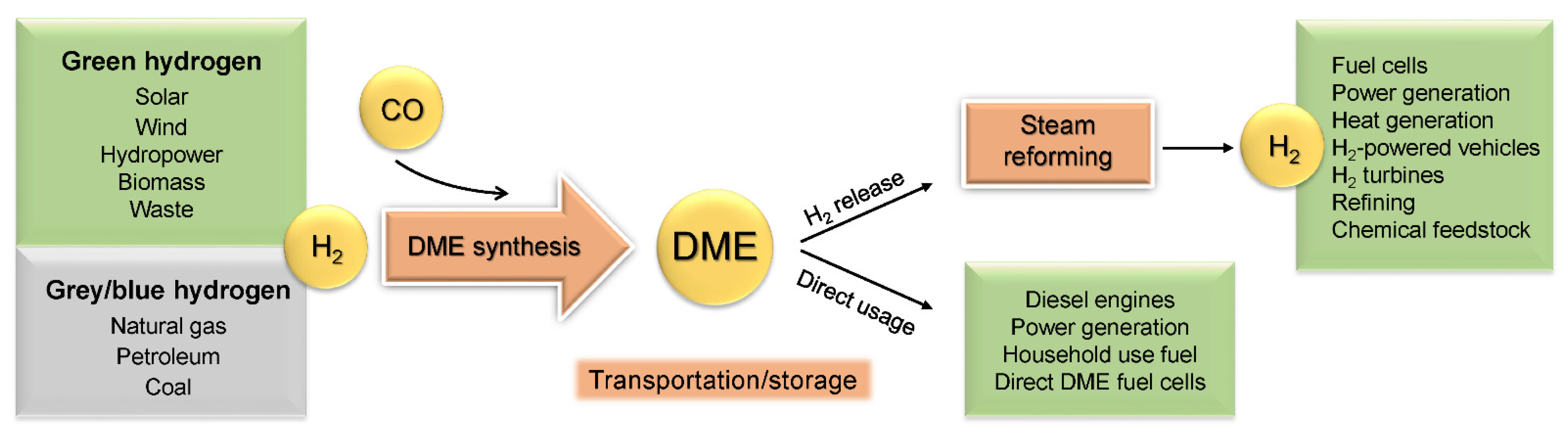
The process of methane steam reforming takes place in the presence of a catalyst. The release of hydrogen from a methanol molecule may be performed in both homogeneous and heterogeneous systems. The heterogeneous system using a solid catalyst is preferred due to the simplicity of the catalyst separation of generated gas products, unreacted methanol, and water. However, the dehydrogenation of methanol in the homogeneous phase allows for the direct transfer of hydrogen for homogeneous hydrogenation reaction systems [56]. Heterogeneous catalysts applied for the MSR are mainly based on copper or noble metal particles supported on materials of high surface area. However, using of carbide catalysts was also reported [66,67]. Among conventional copper catalysts, commercial CuO/ZnO/Al2O3 and its modification are widely applied mainly due to their availability, high activity, and low price. Nonetheless, copper catalysts suffer from deactivation due to copper particles sintering at temperatures above 300 °C [68] and coking with amorphous and graphitic coke [69]. Another factor affecting the activity of methanol steam reforming is also the acidity of the catalyst [63]. Very strong acid sites lead to the occurrence of side reactions that decrease the selectivity towards hydrogen. The proposed modifications of the catalysts are most broadly related to the improvement of the dispersion of copper particles and the enhancement of their redox properties [68]. Therefore, combining copper species with other active phases, including nickel, platinum, palladium [57,66], zirconium [69], cobalt, and strontium [70], to form heterodimers, alloys, perovskites, or core–shell structures, allowing for increasing and maintaining a high degree of dispersion, has been the subject of intensive research. In Table 4 are presented the characteristics of selected catalysts for MSR and their activity in order to vary process parameters. The performance of MSR catalysts apart from process parameters results from preparation technique, added promoters, and selected support. Among reported preparation techniques for MSR catalysts, the wet impregnation, hydrothermal, coprecipitation, sol–gel, carburization, and solid-phase approaches may be distinguished [57,62,63,68,71,72]. The proposed modifications of the catalysts are most broadly related to the improvement of the dispersion of copper particles and the enhancement of their redox properties [68]. Among promoters for copper catalysts, ZrO2 [68,69], Ga2O3 [73], TiO2 [66], ZnO [71], CeO2 [57,68,74], MgO [71,75], yttrium [72], lithium, sodium potassium [75], and lanthanum [76] have been reported. The amount of promoter added to the catalyst structure strongly affects the catalytic activity; therefore, the selection of the appropriate promoter content is crucial for the activity and selectivity of the methanol steam reforming process. Cheng et al. [71] investigated the effect of magnesium promoter content on Cu/ZnO/Al2O3 catalytic activity. The content of a magnesium promoter ranged from 0% to 7%. They found that increasing Mg up to 5% in the catalysts results in enhancing hydrogen generation. After exceeding the optimal value to 7%, the yield of H2 generation decreases. Apart from the influence of the magnesium amount on the efficiency of hydrogen generation, its influence on the selectivity of the process was observed. Along with the increasing hydrogen generation efficiency, an increased proportion of carbon monoxide was observed. The increased presence of CO resulted from the side reaction between H2 and CO2. Zhao et al. [63] investigated the effect of the modification of copper catalysts supported on y-Al2O3/Al with titanium. The evaluated copper-to-titanium ratio equaled 0, 1.5, 1.9, 2.5, and 3.2. They found that optimal doping with Ti species increases the surface area, stabilizes the copper dispersion, enhances the adsorption of methanol, and improves the copper redox performance by facilitating electron transfer from Cu to Ti. Moreover, the addition of titanium promotes the reduction of the acidity of the catalyst, thus limiting the occurrence of side reactions. It was also reported that a basic promoter, including Na, K, Mg, may be used as a sorbent for generated carbon dioxide, allowing for obtaining a gas stream with an even higher hydrogen content [75].
As supports, mesoporous silica KIT-6 [68], CeO2 [57], y-Al2O3 [63], Al2O3 [71], TiO2 [66], zeolites [69,75], and ZrO2 [77] were used. The role of support includes not only proving the dispersion for copper particles and preventing sintering. Moreover, supports of a highly developed surface area, micro- and mesoporous structures, also contribute to effective heat and mass transfer, promoting the activation, diffusion, and migration of the reactants and intermediated and reaction products [69]. Some reducible supports are reported to strongly interact with active-phase-forming redox couples (e.g., Cu2+/Cu0 and Ce3+/Ce4+ [57].
The efficiency of hydrogen generation and its selectivity strongly depends on process conditions. Ma et al. [62] investigated the effect of MSR temperature on the level of methanol conversion and product distribution in the outlet stream over molybdenum carbide wirelike catalysts. They found that along with the rise of the process temperature, the level of MeOH conversion increased. However, as the process temperature increased from 200 to 400 °C, they noticed a decrease in the hydrogen generation selectivity of the process. Above 250 °C, there was a significant increase in the CO and CH4 contents in the outlet stream up to 10 mol. % and a decrease in the H2 content from 80 to 60 mol. %. Similar results were obtained by Zhao et al. [63]. They also investigated the effect of process temperature on effectivity and selectivity over Ti–Cu–y-Al2O3/Al catalysts. They found that above 275 °C, practically all of the methanol was converted. As the process temperature increased, an increase in the selectivity towards the formation of carbon monoxide was observed. In contrast to the results published by Ma et al. [62], the hydrogen generation efficiency also increased with the process temperature. Araize et al. [57] also observed an increase in hydrogen generation efficiency with increasing temperature, from 0% at 100 °C up to 80% above 250 °C

3. Dimethyl Ether

3.1. General Properties and Applications

Dimethyl ether (DME) is the simplest ether with the chemical formula CH3OCH3. Under normal conditions, it is found as a colorless gas. It can be easily condensed at a temperature of −25 °C and atmospheric pressure, or at a pressure of about 0.5 MPa at a temperature of 25 °C. Therefore, it is widely used and stored in liquid form [78]. Table 5 summarizes selected physicochemical parameters of DME.
DME is a multipurpose fuel and chemical feedstock that can be used in a wide variety of applications, from transportation fuels to power generation and the production of olefins, synthesis gas, and hydrogen [80,81]. Currently, DME is mainly used as an aerosol propellant as an alternative to banned ozone-depleting chlorofluorocarbons (CFCs). Its global warming potential is much lower than that of CFCs. In terms of safety, dimethyl ether is nontoxic and nonmutagenic. However, it should be noted that it is flammable and therefore, requires, proper handling [82,83]. DME also plays an important role as a chemical feedstock. It is used as a substitute for methanol for the synthesis of light olefins and synthetic gasoline. Many other important chemicals can be obtained from DME, including dimethyl sulfate, acetic acid, and methyl acetate [84,85,86,87]. Furthermore, DME has gained great interest as an alternative fuel for diesel, gasoline, and LPG [79,88,89,90,91]. As a compound with high oxygen content (34.8 wt %), it has very good combustion properties. DME does not generate particulate matter (PM) in the combustion process as it has no C–C bonds in its chemical structure. As a “clean” fuel, DME also produces no SOx, while the emissions of NOx and CO are significantly lower compared with conventional fuels. DME has a low autoignition temperature and a high cetane number (55–60); hence, after minor modifications, it can be used in compression-ignition engines. DME is also widely used as a high-quality fuel for household use.
In recent years, DME has attracted interest as a chemical hydrogen carrier [24,80,92,93]. DME has a high gravimetric H2 density (13 wt %) and a higher volumetric H2 density than liquid H2, which are equal to 86.9 kg-H2/m3 and 70.9 kg-H2/m3, respectively [94]. Furthermore, DME has excellent characteristics in storage and transportation. Unlike hydrogen, it can be easily liquefied [95]. Due to the similar properties to LPG, the existing LPG infrastructure can be used for the transport and storage of DME with neither additional safety nor technical precautions [96]. DME has a narrower flammability limit by volume in the air (3.4–17%) compared with H2 (4–74%) [78,94]. Dimethyl ether is nontoxic; hence, there is no danger of contamination in the case of leaking, as with other chemical hydrogen carriers, such as methanol. It is noncorrosive, which is also beneficial in terms of handling and transportation [78]. DME can be easily converted back via steam reforming into high-quality synthesis gas or hydrogen if required, which can then be used, for instance, in fuel cells [24,93,97]. It is important to note that as DME can be used directly as fuel or in direct DME fuel cells (DDMEFCs), direct utilization of DME can be also performed without the need for decomposition [79,98,99,100]. The possible schematic route of DME synthesis, transportation, and utilization is shown in Figure 1.

3.2. DME Synthesis

DME can be produced from a variety of raw materials, including natural gas, coal, petroleum, and biomass [95,101,102,103]. In general, there are two methods of DME production—conventional indirect method and the more recently developed direct technology [78]. Figure 2 shows schematically the indirect and direct methods of dimethyl ether synthesis. The conventional process for DME production is an indirect (two-step) synthesis process whose first step involves natural gas or other feedstock reforming, followed by conversion of the generated synthesis gas to methanol, and the second step is dehydration of methanol to DME [95]. The direct method involves the production of DME directly from synthesis gas on a hybrid catalyst capable of catalyzing both methanol synthesis and its dehydration in a single step [78,96,104]. Particularly, the direct hydrogenation of carbon dioxide to dimethyl ether has attracted great attention [24,105,106]. The utilization of CO2 and renewable H2 to generate dimethyl ether can constitute a key strategy to introduce renewable in the chemical industry chain.
The direct synthesis of dimethyl ether from synthesis gas can be expressed in the following reactions: methanol synthesis from CO (Equation (7)) and methanol dehydration (Equation (8)). Water–gas shift (WGS) reaction (Equation (9)) and methanol synthesis from CO2 (Equation (10)) may also occur. The overall reaction is given by Equation (11) [78]. In the case of synthesis gas containing H2 and CO2, overall reaction is expressed by Equation (12), and reversed WGS reaction may take place [24].
CO + 2 H 2 CH 3 OH ,   Δ H = 90.4 kJ mol ,
2 CH 3 OH CH 3 OCH 3 + H 2 O ,   Δ H = 23.0 kJ mol ,
CO + H 2 O CO 2 + H 2 ,   Δ H = 41.0 kJ mol ,
CO 2 + 3 H 2 CH 3 OH + H 2 O ,   Δ H = 49.4 kJ mol ,
3 CO + 3 H 2   CH 3 OCH 3 + CO 2 ,   Δ H = 245.8   kJ / mol
2 CO 2 + 6 H 2   CH 3 OCH 3 + 3 H 2 O ,   Δ H = 122   kJ / mol
The direct synthesis route of DME takes advantage of a lower thermodynamic limitation due to further in situ conversion of methanol to DME, which shifts its thermodynamic equilibrium towards the formation of more methanol, resulting in higher synthesis gas conversion. Therefore, compared with the indirect route, the direct method leads to lower DME production costs and, hence, is more preferable [96,107,108]. The direct DME synthesis process is most often carried out in a fixed bed reactor or a slurry reactor. The operational temperature used is in the range of 240–280 °C, and the pressure in the range of 30–80 bar [78,96,109,110]. Catalysts for the direct synthesis of DME are bifunctional catalysts consisting of a metallic function for the synthesis of methanol and an acidic function for the dehydration of methanol to DME. Commonly, the CuO–ZnO–Al2O3 (CZA) catalyst is used as a component for methanol synthesis, while solid acid catalysts, such as γ-Al2O3, various zeolites (H-ZSM, HBFZ, HY, H-mordenite), and silica–alumina composites, are well known for dehydrating methanol to DME [109,111,112]. In the case of catalytic hydrogenation of CO2 to DME, the conversion of CO2 over the CZA catalyst was reported to be not sufficient. A good alternative for CZA are Cu/ZnO catalysts containing ZrO2 and TiO2 instead of Al2O3, allowing for higher process efficiency [24,106,113,114,115].
DME production technologies and catalysts are well known and have been extensively reviewed in the literature [24,78,79,95,96,112,116,117]. Furthermore, they are used in the industry by companies, such as Haldor Topsoe, JFE Holdings, and Korea Gas Corporation (KOGAS) [104,107,118,119]. Therefore, the following part of the work focuses on advances in technology for hydrogen release from DME.

3.3. Steam Reforming of DME

Many approaches have been studied to produce hydrogen from DME, such as partial oxidation [120,121,122], autothermal reforming [123,124], and steam or dry reforming [125]. Similarly, as described for MeOH in Section 2.3, DME steam reforming (DME SR) is the most preferable method due to the advantage of having the highest theoretical hydrogen yield; thus, it is the most widely studied method [93,97,126,127,128]. As dimethyl ether has no C–C bonds, it can be reformed at a relatively low temperature (250–450 °C) [128]. Moreover, reaction takes place under low pressure (most often atmospheric pressure); thus, the process does not require an apparatus withstanding high pressures. Optimal process parameters highly depend on the type of catalyst used. Typically, a process is carried out in a fixed bed reactor [129,130,131,132,133]; less frequently, a fluidized bed reactor is used [134].
The steam reforming of dimethyl ether proceeds via two moderately endothermic reactions: the hydrolysis of DME to methanol (Equation (13)) and the steam reforming of methanol (Equation (14)). The overall reaction of dimethyl ether steam reforming is expressed by Equation (15).
CH 3 OCH 3 + H 2 O     2 CH 3 OH ,   Δ H = 37 kJ mol ,
CH 3 OH + H 2 O     3 H 2 + CO 2 ,   Δ H = 49 kJ mol ,
CH 3 OCH 3 + 3 H 2 O     6 H 2 + 2 CO 2 ,   Δ H = 135 kJ mol ,
Carbon monoxide can be formed by reverse water–gas shift reaction (RWGS) (Equation (16)). In addition, under high reforming temperatures or in the case of a strong acidic catalyst, methane can be generated due to DME decomposition (Equation (17)) [135,136].
CO 2 + H 2     CO + H 2 O
CH 3 OCH 3     CH 4 + CO + H 2
Hydrolysis of DME is an equilibrium-limited reaction and is considered the rate-limiting step of the overall reaction of DME steam reforming. Since hydrolysis of DME is a slow step, steam reforming of DME requires higher reaction temperatures than steam reforming of methanol (>250 °C). Tanaka et al. [137] performed thermodynamic calculations on the equilibrium of DME hydrolysis (Equation (13)) and revealed that high DME conversion could not be attained by only hydrolysis of DME. The equilibrium conversion of methanol (Equation (14)) is high in the temperature range for DME steam reforming. Therefore, if methanol conversion by steam reforming (Equation (14)) is high enough, the equilibrium of DME hydrolysis (Equation (13)) will shift to the forward direction, leading to high DME conversion.

Process Parameters and Catalysts for DME SR

As the steam reforming of DME involves two steps, similarly to the direct synthesis of DME, bifunctional catalysts are needed [138]. The bifunctional catalyst consists of both acid sites responsible for the hydrolysis of dimethyl ether and metallic sites for methanol reforming. The hydrolysis of DME takes place over solid acid catalysts, most often alumina or zeolites, while methanol reforming is performed over metallic catalysts, such as Pd-, Pt-, and most often Cu-based catalysts. Depending on the catalyst used, optimal conditions for DME SR vary. Therefore, below we summarize and compare DME SR processes over different catalysts up to date. Selected processes of DME SR over different catalysts and different conditions and their effect on DME conversion and H2 production are summarized in Table 6. The stability of the catalyst was also inserted, as it is a crucial factor in terms of long-term process efficiency. To the best of our knowledge, there are no reports regarding higher-scale technologies for DME SR; hence, we described technologies tested on the laboratory scale.
The Cu-based catalysts are promising in terms of cost effectiveness and activity. The most widely used metallic catalyst for steam reforming of DME is Cu/ZnO/Al2O3. However, common Cu-based catalysts are prone to deactivation due to the sintering of Cu particles [134,141]. With the aim of increasing the durability of Cu-based catalysts, modified catalysts, such as Cu–spinel oxides or alloy, have been tested [128,129,131,137]. Faungnawakij et al. [129] proposed the Cu-based spinel oxides CuB2O4 (B = Fe, Mn, Cr, Ga, Al, or Fe0.75Mn0.25) mixed with γ-Al2O3 for DME steam reforming. They reported that the stability of B metal oxides and the interaction between Cu species and B metal oxides significantly contributed to the catalytic activity and durability. The descending order of the activity was as follows: CuFe2O4, CuFe1.5Mn0.5O4 > CuAl2O4 > CuCr2O4 > CuMn2O4 > CuGa2O4. However, only CuFe2O4, CuFe1.5Mn0.5O4, CuCr2O4, and CuMn2O4 were highly stable at a reforming temperature of 350 °C and at 25 h on stream exhibited DME conversion almost equal to ~84%, ~85%, ~79%, and ~69% respectively. Hydrogen production at 25 h on stream was almost equal to ~31 mL/min for CuFe2O4, ~28 mL/min for CuFe1.5Mn0.5O4, ~26 mL/min for CuCr2O4, and ~23 mL/min for CuMn2O4. In another work by Faungnawakij et al. [142], they further investigated the deactivation and regeneration behaviors of a composite catalyst, CuFe2O4/γ-Al2O3, in the temperature range of 255–380 °C. They revealed that a catalyst deactivated due to the concomitant effects of copper sintering and carbon formation may be regenerated by calcination in air in the temperature range of 500–700 °C. By regeneration in this way, a catalyst degraded after 1100 h of steam reforming achieved the redispersion of copper species through spinel reformation and carbon burning simultaneously, resulting in the full recovery of catalytic performance.
Wang et al. [131] investigated the possibility of the inhibition of sintering Cu particles by the modification of a catalyst with Ni. With this aim, they examined Cu–Ni/γ-Al2O3 catalysts with different metal contents for dimethyl ether reforming at 350 °C. They revealed that Ni improved the dispersion of Cu, increased the interaction between copper and support, and thus inhibited the sintering of Cu particles. The optimal catalyst molar composition was Cu/Ni/Al2O3 = 2:1:17, which exhibited stability over 30 h of experimental test within an almost complete conversion of DME and a H2 production rate above 50 mmol/gh. In addition, they demonstrated that nickel addition suppressed the activity of copper in Cu–Ni–Al2O3 towards catalyzing water–gas shift (WGS) reaction (Equation (18)), resulting in syngas with a higher content of CO than CO2.
CO + H 2 O     CO 2 + H 2
Noble-metal-based catalysts have been reported to be highly active and heat resistant. Ledesma et al. [130] investigated catalytic monoliths containing 1% Pd supported on CeO2, ZrO2, CeZr0.5O2, MnO2, SnO2, Al2O3, WO3, or WO3–ZrO2 in DME steam reforming in the temperature range of 360–550 °C. Among all tested catalysts, Pd/Al2O3, Pd/ZrO2, Pd/CeO2, and Pd/WO3 were the most active for DME conversion, with Pd/ZrO2 showing the highest yield of hydrogen (~31%, ~46%, ~56%, and ~67% at 360, 420, 480, and 550 °C, respectively) with the lowest CH4 yield (~3% at 360 and 420 °C, ~0% at 480 and 550 °C). Yoshida et al. [132] investigated the steam reforming of DME over a PdZn/Al2O3 catalyst at in temperature range of 300–400 °C. DME conversion increased with temperature from ~60% to ~100%, while H2 yield increased from ~45% to ~90%. Moreover, no catalyst deactivation was observed over the tested catalyst during the reaction run at 400 °C for 6 h. In addition, they performed 6 h stability tests over the common catalyst Cu–ZnO/Al2O3 at 400 °C. In contrast, in this case, both DME conversion and H2 yield decreased with reaction time on stream from ~52% to ~40% and from ~25% to ~17%, respectively. Lian et al. [133] investigated the modification of a molybdenum carbide catalyst with Pt in order to improve the stability of the catalyst. Both catalysts were tested in the steam reforming of DME at 300–500 °C. The 2%Pt–Mo2C/Al2O3 catalyst resulted in an enhanced catalytic performance in the DME SR reaction, as the highest DME conversion rate increased from 45.7% to nearly 100%, and the H2 production rate increased from 1079 to 1605 µmol/ming at 350 °C. In comparison with an unmodified catalyst, the Pt–Mo2C/Al2O3 catalyst exhibited better low-temperature activity and lower yields of CO and CH4 byproducts. In order to compare the stability of catalysts, experimental tests were performed at 350 °C within 50 h time on stream. The Pt–Mo2C/Al2O3 catalyst was more stable with only 20% loss of its initial conversion after 50 h on stream, while the DME conversion rate decreased from 96.2% to 25% after a 12 h stability test over an unmodified catalyst. The better stability of a Pt-modified catalyst was attributed to the acceleration of the consumption of intermediate oxygen species on the catalyst surface and the lower onset temperature of DME SR reaction (from 400 °C for unmodified catalyst to 350 °C after modification with Pt), which prevented molybdenum carbide from being oxidized.
DME steam reforming effectivity strongly depends on the acidic catalyst that is active for DME hydrolysis. Solid acid catalysts, such as zeolites and γ-Al2O3, are widely used as DME hydrolysis catalysts [93,127,137,143]. Metal catalysts supported on ZSM-5 zeolite are reported to be active below 300 °C due to its strong acid sites. Nonetheless, it leads to coke formation, and thus deactivation. On the other hand, Al2O3 with weaker acid sites has been reported to be more resistant to coke deposition [137,144,145]. However, such systems require higher temperatures compared with zeolites. Faungnawakij et al. [139] investigated the role of a solid–acid catalyst on the hydrolysis and steam reforming of DME. Various zeolites (H-modernite and ZSM-5 type) and alumina catalysts that provide a variety of acid properties were mechanically mixed with CuFe2O4 spinel and tested in steam reforming in the temperature range of 200–450 °C. The effects of different solid acid functions on DME SR are summarized in Table 7. It was found that not only the acid amount of the acidic catalysts but also the type of acid site and the acid strength affect the steam reforming and DME hydrolysis activity. Zeolites exhibited high activity for DME SR in the low temperature range of 250–275 °C, since the hydrolysis could effectively proceed over strong Brønsted acid sites approaching the equilibrium. Alumina catalysts possessing Lewis acid sites were active in the higher temperature range of 300 to 450 °C. A catalyst with γ-Al2O3 exhibited the highest DME conversion and hydrogen production with the optimum reforming temperature at 350–375 °C. Moreover, this catalyst showed the highest stability for DME hydrolysis with high durability for 25 h.
Wang et al. [140] examined an amorphous silica–alumina composite with regulated acidity for the efficient production of hydrogen via steam reforming of dimethyl ether. In this aim, they mixed silica–alumina of different acidities with metallic Cu–ZnO–Al2O3 and carried out DME SR processes over obtained bifunctional catalysts. The processes were performed in the temperature range of 300–350 °C. Similarly, they indicated that the total amount of acidic sites was the crucial factor in determining the reforming performance of the hybrid catalyst. A catalyst with the highest amount of acid sites (mainly weak sites) exhibited the highest DME conversion and the highest H2 yield around 70% at 300 °C. Moreover, by increasing the reaction temperature from 300 to 350 °C, the DME conversion and hydrogen yield further increased to nearly 100%. In addition, they performed a stability test at 350 °C, and both DME conversion and hydrogen yield were kept over 66 h without any observable decreases.

4. Dibenzyltoluenes

Among attractive liquid organic hydrogen carriers (LOHCs), the dibenzyltoluene (H0-DBT)/perhydrodibenzyltoluene (H18-DBT) system is of particular interest [32]. It was first proposed for this application in 2014 by Brückner et al. [146]; however, the hydrogen-lean form (H0-DBT) has been used in the industry since the 1960s as a heat transfer oil (sold under the trade name Marlotherm SH, Farolin, or Diphyl) [147]. The oil is available in technical quantities at a relatively low price in the form of an isomeric mixture (2–4 EUR/kg on a ton scale) [148]. In 2013 Hydrogenious LOHC Technologies GmbH (Erlangen, Germany) started to commercialize hydrogen storage technologies based on mono- and dibenzyltoluene systems [20]. Currently, the company offers plants with a hydrogen release capacity starting from 1.5 tons per day [149]. A French company, Framatome has been testing the H0-DBT/H18-DBT LOHC system since 2014 in the power-to-hydrogen concept [28]. This industrial-scale demonstration of DBT-based technology is a consequence of preferable properties of these compounds for chemical hydrogen storage.

4.1. Properties of DBT

Dibenzyltoluenes are liquid aromatic compounds of well-documented physicochemical and toxicological properties (Table 8) [150,151]. They are characterized by a high hydrogen storage capacity of 6.2% wt (58 g of H2 per L of H18-DBT), corresponding to 2.05 kWh kg−1 [28]. A wide range of temperatures in which DBTs are in a liquid state ensures convenient transport and storage even at subzero temperatures without transition to a solid phase. Low vapor pressure enables the easy separation of hydrogen from the H0-DBT/H18-DBT system by the simple condensation of the H2 carrier and the production of pure hydrogen (>99.98% of purity) [20]. Their hydrocarbon character permits the handling of this carrier in the existing infrastructure for liquid fuels. An important fact is that H0-DBT is nonflammable, nontoxic, and nonmutagenic or noncarcinogenic. The toxicity potential indicator (TPI) of H0-DBT is 13.8 TPI/mg (values: 0 for a substance with no known hazard and 100 for a highly hazardous substance). However, for the hydrogenated form, H18-DBT, no toxicity data are available. Both H0-DBT and H18-DBT are characterized by good thermal stability—their working temperature is in the range of 70–380 °C [27]. The weaker point of the system is its relatively high viscosity, which increases pumping resistance. At low temperatures, the increasing viscosity can be problematic from a technical point of view.
The benzyltoluene (H0-BT)/perhydrobenzyltoluene (H12-BT) system is characterized by lower dynamic viscosity than H0-DBT/H18-DBT (3.94 and 6.97 mPa s for H0-BT and H12-BT, respectively); thus, it is more convenient for winter applications [20]. However, the benefits of DBT over BT are its higher boiling point and low vapor pressure as well as slightly higher volumetric hydrogen storage density (58 vs. 56 kg-H2/m3 for DBT and BT, respectively) [20].

4.2. Reversible Hydrogen Storage

Hydrogenation and dehydrogenation of aromatic compounds are a mature technology, frequently applied, for example, in the refining industry. Thus, the implementation of H0-DBT/H18-DBT on a big scale is not particularly challenging.
The DBT molecule consists of three aromatic rings, which can be hydrogenated in three steps by nine moles of H2. Thus, besides the final product, H18-DBT, intermediate products with different degrees of aromatic ring saturation (H6-DBT, H12-DBT) can be formed. Studies of H0-DBT hydrogenation with Ru/Al2O3 as a catalyst carried out by Do et al. [147] showed that two side rings of DBT molecule are saturated in the first stages, and the middle ring is hydrogenated last. The authors concluded that the saturation of the middle ring is the rate-controlling step, and it takes place only when almost all DBT molecules are converted into H12-DBT when Ru/Al2O3 is used. As H0-DBT is sold as an isomeric mixture, in the hydrogenated product, many compounds can be present (isomers of fully hydrogenated form, but also partially saturated compounds). Hydrogenation is an exothermic, catalytic process; however, it requires increased temperature and pressure. The obtained product molecule, H18-DBT, stores nine moles of hydrogen, which can be released on demand in an endothermic process. The dehydrogenation is usually carried out under normal or slightly increased pressure and at high temperatures in the presence of an appropriate catalyst. The schematic representation of the H0-DBT/H18-DBT system is shown in Figure 3.

4.2.1. Hydrogenation Process

The saturation of hydrogen-lean H0-DBT to hydrogen-rich H18-DBT is a catalytic process carried out at high pressure and elevated temperatures, which depend on the type of used catalyst (Table 9). Typically, noble-metal-derived, eggshell catalysts are applied due to their high activity and selectivity [152]. Ru- and Rh-bearing materials are usually suitable for catalyzing the reaction at temperatures below 220 °C, whereas Pt-based catalysts are used for hydrogenation above 220 °C [20]. Jorschick et al. [153] determined that increasing the temperature of reaction catalyzed by Ru/Al2O3 or Rh/Al2O3 decreases the activity of the catalysts and results in by-product formation (Table 10). The analysis of the gas phase after hydrogenation showed the presence of impurities, such as carbon dioxide, and C1–C3 alkanes. It was postulated that CO2 originates from traces of water in a catalytic support and technical-grade H0-DBT, whereas methane is formed due to decomposition side reactions. At temperatures higher than 200 °C, the methane concentration in the off-gas increased significantly, especially in the case of Ru-catalyzed reaction, which indicates that the catalyst promotes hydrocracking reactions. The increase in temperature for Pt- and Pd-catalyzed reactions did not have such a drastic effect on methane generation. In the hydrogenated mixture, besides gaseous products, other impurities are lower-boiling compounds (such as benzyltoluene, benzene, toluene) and higher-boiling compounds, which are present in commercial H0-DBT (i.e., Marlotherm SH).
Shi et al. [155] investigated the effect of various supports (Al2O3, hydroxyapatite (HAP), activated carbon, and mesoporous silica (SBA-15)) on Pt catalyst activity for the hydrogenation of H0-DBT. Under the process conditions (30–40 bar, 140 °C), the performance of the catalysts bearing 5% of Pt can be set in the order: Pt/Al2O3 > Pt/SBA-15 > Pt/HAP > Pt/C. The DBD (dielectric barrier discharge) plasma modification of Al2O3 ensured higher activity of 3% Pt/Al2O3 in comparison with the respective catalyst with unmodified support due to the increased amount of hydroxyl groups on the Al2O3 surface [157].
Although noble metal-based materials are effective catalysts for H0-DBT hydrogenation, their large-scale utilization is not a perfect solution due to the metal price and scarcity. Ali et al. [32] reported that Raney-Ni could be a cost-effective catalyst for DBT hydrogenation. They compared the material activity with two other catalysts, 5% Ru/Al2O3 and 5% Pd/Al2O3, using a stirring-type reaction under a low pressurized system (9 bar). The most favorable temperature of the process was 170 °C, and the catalytic performance decreased in the order: Raney-Ni > Pd/Al2O3 > Ru/Al2O3. Under these conditions, the application of a Raney-Ni catalyst ensured 21% of hydrogenation. The utilization of another Ni-based catalyst, NiSat 310, allowed much higher hydrogen loading (98%) when higher pressure (15 bar) was applied [156]. These results indicate an interesting direction for future works on DBT hydrogenation catalysts.
Hydrogenation of H0-DBT can be carried out by using not only pure hydrogen but also hydrogen-rich mixtures, which is very attractive from an economical point of view [20]. Gaseous mixtures with high hydrogen content can be a side product of technological processes (e.g., catalytic reforming, coal pyrolysis), whereas wet hydrogen is obtained after water electrolysis. Their direct utilization for chemical hydrogen storage without the need for gases’ separation can eliminate investment and operation costs related to purification units (like PSA (pressure swing adsorption)). Jorschick et al. [153] tested H0-DBT hydrogenation by wet hydrogen (20 mol. % water) to evaluate the necessity of hydrogen drying after water electrolysis. Experiments carried out over alumina-supported Ru, Rh, Pd, and Pt showed that the presence of water slightly decreases the reaction rate of all catalysts except Ru. However, for a reaction with this catalyst, a much higher concentration of methane and carbon dioxide in the off-gas was detected with a comparison with hydrogenation by pure hydrogen (6605 vs. 1502 ppm and 95 vs. 8 ppm for CH4 and CO2, respectively, Table 10). In the case of a Pt-bearing catalyst, the presence of water had the most significant inhibition effect on the final hydrogenation step to H18-DBT. The productivity P80–90 dropped from 1.59 gH2 gcat−1 min−1 with pure hydrogen to 0.30 gH2 gcat−1 min−1 with 20 mol. % water, resulting in only 46% conversion to H18-DBT. Dürr et al. [154] determined that the methane–hydrogen mixture, which can be obtained from the catalytic methane decomposition, has no adverse effect on the reaction rate of H0-DBT hydrogenation over Ru/Al2O3 at 180 °C. Under experimental conditions (pH2 = 40 bar, pCH4 = 20 bar), a slight increase in hydrogen uptake was observed, which was explained by a reduction of the system viscosity (due to dissolved methane) and a resulting improvement in hydrogen diffusion into the liquid phase. In the case of a hydrogen-rich mixture containing up to 30% of carbon dioxide, the activity of alumina-supported Ru, Rh, Pd, and Pt catalysts towards methanation was evaluated [158]. Due to this competitive process, in which hydrogen reacts with carbon dioxide, forming methane and water (ΔH = −165 kJ/mol), the hydrogenation of H0-DBT can be less efficient [20]. Under measurement conditions (tested temperatures: 100–240 °C), none of the catalysts achieved complete hydrogenation. Although very active in reaction with pure hydrogen, the Pt-based catalyst in the presence of carbon dioxide revealed very low effectiveness (DoH: 2%). Ru/Al2O3 strongly promoted undesired methanation reaction. The highest activity for H0-DBT hydrogenation at low temperatures showed Rh/Al2O3, whereas Pd-based material was characterized by the lowest selectivity to methane formation at temperatures above 200 °C. Analogous experiments carried out with Rh/C showed that the support change increased the productivity (from 0.39 to 0.84 gH2 gcat−1 min−1 for Al2O3 and C support, respectively) and reduced the methane-to-carbon dioxide ratio in the off-gas (from 0.075 to 0.002) [159]. Jorschick et al. [4] described that short injections of CO to the system hydrogenated with pure hydrogen lead to the deactivation of alumina-supported Ru, Rh, Pd, and Pt catalysts. However, the conversion of carbon oxide to methane resulted in the regeneration of all four catalysts over the process time. Among tested catalysts, Pd/Al2O3 showed the best compatibility with CO, even when a mixture with 10% CO was continuously added to the system at a temperature of 320 °C. In the case of Ru, Rh, and Pt catalysts, the presence of CO in the feedstock led to permanent deactivation. The results described above show that among tested catalysts, the most suitable for a hydrogen-containing mixture is Pd/Al2O3. Thus, Jorschick et at. [4] evaluated the utilization of this catalyst for multicomponent gas mixtures. Hydrogenation experiments with model mixtures resembling the composition of the gas obtained in the natural gas steam reforming process (78% H2, 20% CO2, and 2% CO) and coke oven gas (60% H2, 31% CH4, 7% CO, 2% CO2) revealed good selectivity of the catalyst towards the desired reaction at 270 and 300 °C, respectively.

4.2.2. Dehydrogenation Process

The release of hydrogen from H18-DBT is an endothermic reaction with enthalpy equal to 65.4 kJ mol−1, which corresponds to around 27% of the lower heating value (LHV) of hydrogen [20]. Hydrogenious LOHC Technologies GmbH states that their release plants of hydrogen outlet 1.5 t per day require 780 kWth of heat [149]. On the one hand, the necessity of such high thermal energy involves high operation costs, but on the other hand, it ensures the system safety. A much lower heat of the dehydrogenation would cause the incidental release of stored hydrogen if a tank with hydrogen-rich compounds and catalytically active metals warms up in the sunshine.
The most commonly tested catalysts for H18-DBT dehydrogenation are summarized in Table 11. As in dehydrogenation, elevated temperatures are required, and a suitable catalyst should not only show good selectivity but also display high resistance against thermal deactivation (sintering). Brückner et al. [146] determined that among tested commercial catalysts, the most efficient was activated carbon-supported platinum material (1% wt). After 3.5 h of the process carried out at 290 °C, the degree of dehydrogenation (DoD) was 98%. Contrary to the results obtained for hydrogenation, alumina support was less effective for dehydrogenation than activated carbon. The Pd-bearing catalysts supported on Al2O3 and C were less active than Pt materials. Ali et al. [160] determined that the optimum temperature of dehydrogenation is 290 °C when 3% Pt/Al2O3 is used. A higher temperature (320 °C) ensures higher DoD values; however, it also promotes undesired side reactions, such as ring opening and cracking of DBT [155]. The increase in Pt loading on catalysts obtained by Ali et al. [160] resulted in a higher DoD at 290 °C (71.1–90.2% for Pt loading on Al2O3 1–5% wt). Similar findings were described for this catalyst by Modisha et al. [161]. At 320 °C, DoD was 50%, 80%, 96% for 0.5%, 1%, and 2% wt, respectively. The authors reported that at low temperatures (290 °C), the dehydrogenation kinetics is slow, but hydrogen is obtained with high purity (99.99%). At a higher temperature (320 °C), the reaction runs faster; however, more methane is generated, and hydrogen purity decreases to 99.96%. Bimetallic Pt–Pd and Pd-based catalysts (supported on Al2O3) tested in the range of 260–320 °C showed a much lower activity in dehydrogenation than pure Pt/Al2O3. The activation energy values for 1% wt Pt/Al2O3, 1% wt Pd/Al2O3, and 1:1% wt Pt–Pd/Al2O3 were: 205, 84, and 66 kJ/mol, respectively.
Modisha et al. [156] investigated the cyclic hydrogenation/dehydrogenation of DBT under stress conditions. The hydrogenation process was carried out in the presence of NiSat 310 (Table 3) at 150 °C, and under 15 bar, whereas for dehydrogenation, higher temperatures were used: 300 °C for cycles 1–5 (2 h of the process for each cycle), 320 °C for cycles 6–10 (time—3 h), and 340 °C for cycles 11–16 (time—4 h). As a catalyst for dehydrogenation, 1% wt Pt/Al2O3 was used. The average DoH for all cycles was 98%, and the content of by-products increased from 0.4 to 5.3 mol. %. The analysis of the products of dehydrogenation showed that after the first five cycles, the number of by-products was 4.7 mol. %. The increase in dehydrogenation temperature resulted in 5.8 and 6.5 mol. % of by-products for 320 and 340 °C, respectively. Based on a chromatographic analysis, it was determined that besides gaseous by-products (CH4, CO2), compounds such as monobenzyltoluenes (MBTs), benzene, xylenes, toluene, and benzylmethylfluorenes were formed under the process conditions. It was reported that a Ni-based catalyst promotes isomerization and Pt-catalyzed hydrogenation produces less side products.
Jorschick et al. [4] evaluated the purity of released hydrogen from H18-DBT charged previously by H2/CO2/CO mixture (78:20:2 v/v). Under 0.3% wt Pt/Al2O3 and dehydrogenation temperatures of 290, 300, and 310 °C, the purity of generated hydrogen was lower, but after 60 min, all physically bound gases escaped from the reactor, and the purity of hydrogen increased (99.99%). At the highest tested temperature and a longer reaction time, the purity decreased to 99.97%. The detected contaminants were short-chain alkanes (250 ppm), cyclic hydrocarbons (10 ppm), carbon dioxide (13 ppm), and carbon monoxide (7 ppm).
Generally, hydrogenation and dehydrogenation of H2 storing materials are carried out in two separated reactors [19,21,27]. This setup makes the hydrogen storage process more complex and limits the flexibility of the system due to extended heating time, which is necessary to bring a reactor from standby to operation conditions. Developing a DBT hydrogenation/dehydrogenation technology in one reactor may offer high dynamics in switching from hydrogen charging to its release and ensure heat integration between these two processes. Shi et al. [155] applied 3% wt Pt/Al2O3 as a catalyst for both hydrogenation and dehydrogenation carried out in a single batch reactor. Optimal temperatures of 140 and 270 °C for hydrogenation and dehydrogenation were determined to ensure a low number of side products. Five cycles of integrated hydrogenation and dehydrogenation showed a decrease in hydrogenation capacity and an increase in hydrogen storage efficiency upon the cycles. It was concluded that the lower activity of the catalysts resulted from carbon deposition on the catalyst surface and side reactions of DBT.

5. Comparison of MeOH, DME, and DBT Properties and H2 Storage Technologies

The properties of particular candidates for the hydrogen carrier are compared in Table 12. The highest volumetric density of hydrogen among the described carriers is that of methanol. It is equal to 99 kg-H2/m3, which is 1.4 times higher than that of liquid hydrogen. However, MeOH is highly toxic, which causes difficulties in handling and may cause serious issues in the case of leakage. Moreover, the compound is flammable. Dimethyl ether has a slightly lower H2 volumetric density, equal to 87 kg-H2/m3, which is 1.2 times higher than that of liquid hydrogen. What is more, it has the highest gravimetric hydrogen density (13 wt %) among investigated H2 carriers. Contrary to methanol, it is nontoxic. Under normal conditions, DME is found in gaseous form, but it can be easily liquefied; thus, it is most often used and transported in the industry in liquid form. Due to its properties similar to LPG, the existing LPG infrastructure can be used for its transport and use. On the other hand, DBT is characterized by the lowest gravimetric and volumetric hydrogen density, 6.2 wt % and 58 kg-H2/m3, respectively. However, it takes great advantage of the possibility of cyclic use and good properties, such as nontoxicity and nonflammability. Moreover, this H2 carrier is compatible with the existing fossil fuel transport infrastructure.
Hydrogen storage technologies are different for all investigated carriers. These technologies are listed in Table 13 along with the process parameters, the most common catalysts and their advantages and disadvantages summarized. MeOH and DME allow for the one-way transport of H2—from production to the utilization sites. The key steps in this technology are the synthesis and subsequent release of hydrogen in processes, such as partial oxidation, autothermal reforming, and steam or dry reforming. Among them, steam reforming of these H2 carriers seems to be the most preferable due to the advantage of having the highest theoretical hydrogen yield. The syntheses of DME and MeOH can be carried out using a wide variety of raw materials, including natural gas, coal, petroleum, and biomass. Attention should be paid to the possibility of the utilization of CO2 for synthesis. Combined with the use of renewable hydrogen, it is a very promising method in terms of sustainable development. For the synthesis of MeOH, catalysts based on Cu, most often CuO/ZnO/Al2O3, are used. In the case of direct DME synthesis, bifunctional catalysts combining a metal function (as the aforementioned CZA) and acid sites for methanol dehydration, mainly alumina and zeolites, are used.
Different from MeOH and DME, the technology of hydrogen storage in DBT is based on the cyclic use of the same carrier for hydrogenation and dehydrogenation sequentially. Besides, H2-rich mixtures can also be used for the hydrogenation of DBT, which is a great advantage from an economic point of view. DBT hydrogenation can be carried out under conditions of lower temperatures (150–260 °C) and lower pressure (3–50 bar) compared with the syntheses of MeOH and DME (220–230 °C, 50–100 bar; 240–280 °C, 30–80 bar, respectively). Although the hydrogenation conditions are more favorable in this case, the hydrogen capacity in DBT is much lower. The most commonly used catalysts for DBT hydrogenation are noble metal catalysts (Pt-, Pd-, Ru-, Rh-based catalysts); however, the use of nickel-based catalysts has also been reported with the aim of reducing costs.
The release of hydrogen from all compared carriers takes place mainly in conditions of low temperature and atmospheric pressure. Similar to the first stage, the hydrogen release stage is catalytic. The use of the same catalyst for both steps should be considered as this would simplify the process, thus reducing costs. This is possible with MeOH, DME, and DBT. In the case of MeOH, copper-based catalysts can be used for both synthesis and steam reforming (e.g., commercial CZA). Similarly, for DME synthesis and its steam reforming, bifunctional catalysts containing a metallic function (for MeOH synthesis and MeOH reforming, respectively) and acid function (for MeOH dehydration and DME hydrolysis respectively) are needed; hence, one catalyst could be used for both of these steps. For DBT, both hydrogenation and dehydrogenation were successfully performed using the same Pt/Al2O3 catalyst.
The generated hydrogen can then be used in H2 fuel cells, for power and heat generation, H2 powered vehicles, and more. However, the possibility of contamination in the gaseous product and the introduction of additional steps in its purification (e.g., PSA or membrane separation methods) should be considered. Besides CO2, the presence of CO and short-chain hydrocarbon by-products have been reported. For DBT, other impurities present even before hydrogenation in a commercial substance, such as benzyltoluene, benzene, and toluene, should be considered. It should be emphasized that due to their beneficial properties, both MeOH and DME can be used directly without the need for decomposition, as a fuel or in direct MeOH fuel cells or direct DME fuel cells.

6. Final Remarks

Diminishing of raw materials for the current fossil fuel economy and a growing demand for energy require a transition to the new economy regime. The hydrogen economy can make a significant contribution to making the energy sector independent of oil, natural gas, and coal, although such a transition is challenging. One of challenges that need to be overcome to successfully implement a future hydrogen economy is storage and transport technology. Due to the high energy demand related to the compression and liquefaction of hydrogen, the low volumetric energy density, and the explosive nature of hydrogen, research was undertaken on the hydrogen storage and transport strategies. With this aim, numerous compounds, such as porous carbon-based materials, MOFs, zeolites, and chemical hydrogen carriers have been tested. However, as we described in this work, many of these compounds are of no practical importance from the perspective of large-scale applications due to factors such as safety concerns, toxicity, low hydrogen capacity, very high costs, and lack of appropriate infrastructure. Therefore, emphasis must be placed on the development of effective hydrogen technologies so that a sustainable energy economy may become a reality. Among the available hydrogen storage strategies, using chemical hydrogen carriers seems to be the most promising. Although these technologies include many operations, such as production of the chemicals, separation, catalyst production and recovery, and dehydrogenation, they seem to be the most convenient compared with the currently used hydrogen storage technologies. Due to their high gravimetric capacity of hydrogen, the ease of hydrogenation and hydrogen release (moderate process conditions, low energy costs, no complicated apparatus), and the opportunity to use the existing oil and gas infrastructure, these seemingly complex technologies compared with the currently used hydrogen storage technologies turn out to be extremely interesting and constitute a great path for further development.
A suitable H2 carrier designed for energy storage and transport and as a fuel for mobility applications should fulfill several requirements. Considering energy storage, factors such as storage capacity and energy demands are essential. An ideal material for this application should have high stability, which ensures the safety of the storage system and many cycles of hydrogenation–dehydrogenation. The material should be readily available and nonexpensive. For energy transport, next to availability, the toxicological properties of the carrier are crucial. The material should be nontoxic, nonflammable, and stable under transportation conditions. The successful application of H2 carriers in the mobility sector requires a high storage capacity and a high energy density of the material. These factors affect the size and weight of onboard fuel tanks. According to the specifications of the US Department of Energy (DOE), the current onboard targets are 1.5 kWh/kg (corresponding to 4.5 wt %), 1.0 kWh/L, and USD 10/kWh [162]. The process dynamics and dehydrogenation temperature are other factors that have to be considered for mobility applications. In an ideal situation, the heat demand of dehydrogenation is covered by waste heat from a fuel cell. However, if the temperature ensuring fast dehydrogenation is higher than 180 °C, the heat demand is difficult to realize by PEM fuel cells [163]. The purity of hydrogen released from the system is also of high importance, as contaminants (such CO) may poison a fuel cell catalyst.
From a practical point of view, the proposed recommendations for hydrogen carriers seem to be too restrictive and practically impossible to meet by most of the available solutions, and thus, compromises should be sought. Taking into account the functional aspects of hydrogen carriers and the expectations of representatives of the oil and gas industry, we should focus on what is currently available on the market and can be adapted to transport hydrogen using various carriers. The following points propose considerations for each of the examples described in the work, based on cooperation with the oil and gas sector in relation to the three most important aspects of the use of hydrogen carriers.

6.1. Energy Storage

In energy storage, it would theoretically seem that one of the most important points is the hydrogen storage capacity. Although this is a crucial factor, it should be noted that from a technological point of view, the ease of obtaining hydrogen from the support is equally important in relation to its hydrogen capacity. This applies not only to the technology of reversing the hydrogen enclosure reaction in a chemical compound, but also to the operation and complexity of the equipment for recovering hydrogen from the carrier, as well as the size of the installation itself. Taking into account the technological requirements and the production process of hydrogen recovery from the carrier, DBT seems to be the most sensible of the analyzed compounds for energy storage.
A relatively high storage capacity of DBT makes this material a good option for energy storage. DBT is in liquid form in a wide range of temperatures, which ensures the effective separation of released hydrogen from the storage system. High temperatures of hydrogenation–dehydrogenation processes provide stability to the stored liquid. However, the consequence of dehydrogenation conditions are increased operation costs. Nevertheless, comparing with MeOH and DME, DBT does not need advance installation for the reforming and separation of the products.
Additional problems with storing hydrogen in MeOH and DME are the toxicity of MeOH and the explosiveness of DME. Based on industrial experience, it is much easier to secure the possibility of DME storage, as the explosion limits are subject to limits and the possibility of creating an explosive atmosphere can be effectively prevented, much easier than in the case of compressed/liquefied hydrogen. Unfortunately, when it comes to toxic compounds, such as MeOH, their use for storage is possible only in protected areas because they are harmful even in case of small leakage. On the other hand, leakage protection solutions are widely available in the industry. Both DME and MeOH should be seriously taken into consideration due to a very high hydrogen density and many other applications in the industry.

6.2. Energy Transport

DBTs are a good candidate for energy transport. Actually, the technology of DBT usage in such applications has already been stated. Hydrocarbon character, low melting point, and high boiling point cause this H2 carrier to be compatible with existing fossil fuel transport infrastructure. H0-DBTs have well-documented physicochemical and toxicological properties. They are considered safe for environment compounds. However, the properties and biological activity of the hydrogen-rich form H18-DBT have not been widely investigated yet.
When it comes to methanol and DME, they should not cause problems in transport from a physicochemical point of view. Under normal conditions, methanol is liquid, whereas DME condenses under slight pressure. Unfortunately, taking into account the safety issues, they seem to pose a risk in transport. Methanol is highly toxic and potentially very harmful and dangerous to both the environment and humans. It requires special safety measures and tight devices when loading and unloading the tanker, and a possible accident of the tanker or damage to the pipeline will always be associated with the risk of a negative impact on the environment. Dimethyl ether seems to be a much better choice as it is considered environmentally friendly [164], and although it poses little risk due to its flammable and explosive properties, it is much safer to transport than natural gas or hydrogen.
Considering that all three carriers can be successfully transported both in tanks and by pipelines, and only methanol in the event of a leak poses a direct threat to the environment and human life due to its toxicity even at low concentrations, mainly DBT and DME should be considered for the transport of hydrogen. Both compounds have a relatively high hydrogen density, and possible leakage into the environment has much less negative consequences than MeOH. In addition, they can be placed on the market using the existing network of pipelines and conventional transport without the billions of investment costs needed for the eventual transport of hydrogen in pure form.

6.3. Mobility

Due to kinetic and thermodynamic reasons, DBTs do not have significant potential in onboard applications. Unfortunately, apart from promising properties as a hydrogen carrier, the use of a heavy organic compound as a fuel or a hydrogen source for fuel cells does not seem to be implementable. The situation looks better in the case of methanol, which theoretically can be used as a fuel [41]. Unfortunately, in this case, strong toxic and corrosive properties and a very low cetane number have a significant more negative impact on its applicability. DME is much better in terms of use in mobility. Due to its high cetane number and high energy efficiency during combustion in a diesel engine, it seems to be an ideal substitute for it. A slight modification of the engine and the power supply system allows for the elimination of diesel fuel with virtually zero particulate emissions [165]. DME does not have to be converted to hydrogen for mobile applications as in this respect, it can be a standalone fuel, and when such a need arises, it can be directed to obtain hydrogen for other purposes in accordance with the previously described processes. From the analyzed hydrogen carriers, DME seems to be the best for the purposes of using the generally understood mobility in the market.
Taking into account the analysis of using the presented hydrogen carriers in energy storage, energy transport, and mobility, we can conclude that all of them have not only theoretical but also confirmed practical potential to be implemented in a growing hydrogen market. Depending on the specific use, energy prices, and availability of the infrastructure, all of them can be widely used simultaneously in different places of a future “hydrogen world”.

Author Contributions

Conceptualization, E.P., N.Ł., I.W. and A.R.; writing—original draft preparation, E.P., N.Ł., I.W. and A.R.; writing—review and editing, E.P. and J.G.; supervision, J.G.; project administration, J.G.; funding acquisition, J.G. All authors have read and agreed to the published version of the manuscript.

Funding

This research received no external funding.

Informed Consent Statement

Not applicable.

Data Availability Statement

Not applicable.

Conflicts of Interest

The authors declare no conflict of interest.

References

  1. European Commission. A Hydrogen Strategy for a Climate-Neutral Europe; Com(2020) 301; European Commission: Brussels, Belgium, 2020. [Google Scholar]
  2. Abdin, Z.; Zafaranloo, A.; Rafiee, A.; Mérida, W.; Lipiński, W.; Khalilpour, K.R. Hydrogen as an energy vector. Renew. Sustain. Energy Rev. 2020, 120, 109620. [Google Scholar] [CrossRef]
  3. Wolf, E. Large-Scale Hydrogen Energy Storage. In Electrochemical Energy Storage for Renewable Sources and Grid Balancing; Elsevier: Amsterdam, The Netherlands, 2015; pp. 129–142. [Google Scholar] [CrossRef]
  4. Jorschick, H.; Vogl, M.; Preuster, P.; Bösmann, A.; Wasserscheid, P. Hydrogenation of liquid organic hydrogen carrier systems using multicomponent gas mixtures. Int. J. Hydrogen Energy 2019, 44, 31172–31182. [Google Scholar] [CrossRef]
  5. Eberle, U.; Felderhoff, M.; Schüth, F. Chemical and physical solutions for hydrogen storage. Angew. Chem. Int. Ed. 2009, 48, 6608–6630. [Google Scholar] [CrossRef] [PubMed]
  6. Mazloomi, K.; Gomes, C. Hydrogen as an energy carrier: Prospects and challenges. Renew. Sustain. Energy Rev. 2012, 16, 3024–3033. [Google Scholar] [CrossRef]
  7. Kanezaki, T.; Narazaki, C.; Mine, Y.; Matsuoka, S.; Murakami, Y. Effects of hydrogen on fatigue crack growth behavior of austenitic stainless steels. Int. J. Hydrogen Energy 2008, 33, 2604–2619. [Google Scholar] [CrossRef]
  8. Wijayanta, A.T.; Oda, T.; Purnomo, C.W.; Kashiwagi, T.; Aziz, M. Liquid hydrogen, methylcyclohexane, and ammonia as potential hydrogen storage: Comparison review. Int. J. Hydrogen Energy 2019, 44, 15026–15044. [Google Scholar] [CrossRef]
  9. Aftab, A.; Hassanpouryouzband, A.; Xie, Q.; Machuca, L.L.; Sarmadivaleh, M. Toward a Fundamental Understanding of Geological Hydrogen Storage. Ind. Eng. Chem. Res. 2022, 61, 3233–3253. [Google Scholar] [CrossRef]
  10. Gabrielli, P.; Poluzzi, A.; Kramer, G.J.; Spiers, C.; Mazzotti, M.; Gazzani, M. Seasonal energy storage for zero-emissions multi-energy systems via underground hydrogen storage. Renew. Sustain. Energy Rev. 2020, 121, 109629. [Google Scholar] [CrossRef]
  11. Tarkowski, R. Underground hydrogen storage: Characteristics and prospects. Renew. Sustain. Energy Rev. 2019, 105, 86–94. [Google Scholar] [CrossRef]
  12. Portarapillo, M.; Di Benedetto, A. Risk assessment of the large-scale hydrogen storage in salt caverns. Energies 2021, 14, 2856. [Google Scholar] [CrossRef]
  13. Crotogino, F.; Schneider, G.S.; Evans, D.J. Renewable energy storage in geological formations. Proc. Inst. Mech. Eng. Part A J. Power Energy 2018, 232, 100–114. [Google Scholar] [CrossRef]
  14. Andersson, J.; Grönkvist, S. Large-scale storage of hydrogen. Int. J. Hydrogen Energy 2019, 44, 11901–11919. [Google Scholar] [CrossRef]
  15. Langmi, H.W.; Ren, J.; North, B.; Mathe, M.; Bessarabov, D. Hydrogen storage in metal-organic frameworks: A review. Electrochim. Acta 2014, 128, 368–392. [Google Scholar] [CrossRef]
  16. Yürüm, Y.; Taralp, A.; Veziroglu, T.N. Storage of hydrogen in nanostructured carbon materials. Int. J. Hydrogen Energy 2009, 34, 3784–3798. [Google Scholar] [CrossRef] [Green Version]
  17. Langmi, H.W.; Walton, A.; Al-Mamouri, M.M.; Johnson, S.R.; Book, D.; Speight, J.D.; Edwards, P.P.; Gameson, I.; Anderson, P.A.; Harris, I.R. Hydrogen adsorption in zeolites A, X, Y and RHO. J. Alloys Compd. 2003, 356–357, 710–715. [Google Scholar] [CrossRef]
  18. Moradi, R.; Groth, K.M. Hydrogen storage and delivery: Review of the state of the art technologies and risk and reliability analysis. Int. J. Hydrogen Energy 2019, 44, 12254–12269. [Google Scholar] [CrossRef]
  19. Niermann, M.; Beckendorff, A.; Kaltschmitt, M.; Bonhoff, K. Liquid Organic Hydrogen Carrier (LOHC)—Assessment based on chemical and economic properties. Int. J. Hydrogen Energy 2019, 44, 6631–6654. [Google Scholar] [CrossRef]
  20. Jorschick, H.; Preuster, P.; Bösmann, A.; Wasserscheid, P. Hydrogenation of aromatic and heteroaromatic compounds-a key process for future logistics of green hydrogen using liquid organic hydrogen carrier systems. Sustain. Energy Fuels 2021, 5, 1311–1346. [Google Scholar] [CrossRef]
  21. Makepeace, J.W.; He, T.; Weidenthaler, C.; Jensen, T.R.; Chang, F.; Vegge, T.; Ngene, P.; Kojima, Y.; de Jongh, P.E.; Chen, P.; et al. Reversible ammonia-based and liquid organic hydrogen carriers for high-density hydrogen storage: Recent progress. Int. J. Hydrogen Energy 2019, 44, 7746–7767. [Google Scholar] [CrossRef]
  22. Chatterjee, S.; Kumar Parsapur, R.; Huang, K.-W. Limitations of Ammonia as a Hydrogen Energy Carrier for the Transportation Sector. ACS Energy Lett. 2021, 6, 4390–4394. [Google Scholar] [CrossRef]
  23. Saxena, S.; Kumar, S.; Drozd, V. A modified steam-methane-reformation reaction for hydrogen production. Int. J. Hydrogen Energy 2011, 36, 4366–4369. [Google Scholar] [CrossRef]
  24. Catizzone, E.; Freda, C.; Braccio, G.; Frusteri, F.; Bonura, G. Dimethyl ether as circular hydrogen carrier: Catalytic aspects of hydrogenation/dehydrogenation steps. J. Energy Chem. 2021, 58, 55–77. [Google Scholar] [CrossRef]
  25. Frei, M.S.; Mondelli, C.; Short, M.I.M.; Pérez-Ramírez, J. Methanol as a Hydrogen Carrier: Kinetic and Thermodynamic Drivers for its CO2-Based Synthesis and Reforming over Heterogeneous Catalysts. ChemSusChem 2020, 13, 6330–6337. [Google Scholar] [CrossRef] [PubMed]
  26. Eppinger, J.; Huang, K.-W. Formic Acid as a Hydrogen Energy Carrier. ACS Energy Lett. 2017, 2, 188–195. [Google Scholar] [CrossRef] [Green Version]
  27. Aakko-Saksa, P.T.; Cook, C.; Kiviaho, J.; Repo, T. Liquid organic hydrogen carriers for transportation and storing of renewable energy—Review and discussion. J. Power Sources 2018, 396, 803–823. [Google Scholar] [CrossRef]
  28. Modisha, P.M.; Ouma, C.N.M.; Garidzirai, R.; Wasserscheid, P.; Bessarabov, D. The Prospect of Hydrogen Storage Using Liquid Organic Hydrogen Carriers. Energy Fuels 2019, 33, 2778–2796. [Google Scholar] [CrossRef]
  29. Shuwa, S.M.; Jibril, B.Y.; Al-Hajri, R.S. Hydrogenation of toluene on Ni-Co-Mo supported zeolite catalysts. Niger. J. Technol. 2018, 36, 1114. [Google Scholar] [CrossRef] [Green Version]
  30. Akamatsu, K.; Ohta, Y.; Sugawara, T.; Kanno, N.; Tonokura, K.; Hattori, T.; Nakao, S.I. Stable high-purity hydrogen production by dehydrogenation of cyclohexane using a membrane reactor with neither carrier gas nor sweep gas. J. Memb. Sci. 2009, 330, 1–4. [Google Scholar] [CrossRef]
  31. Hodoshima, S.; Takaiwa, S.; Shono, A.; Satoh, K.; Saito, Y. Hydrogen storage by decalin/naphthalene pair and hydrogen supply to fuel cells by use of superheated liquid-film-type catalysis. Appl. Catal. A Gen. 2005, 283, 235–242. [Google Scholar] [CrossRef]
  32. Ali, A.; Kumar, G.U.; Lee, H.J. Investigation of hydrogenation of Dibenzyltoluene as liquid organic hydrogen carrier. Mater. Today Proc. 2021, 45, 1123–1127. [Google Scholar] [CrossRef]
  33. Markiewicz, M.; Zhang, Y.Q.; Empl, M.T.; Lykaki, M.; Thöming, J.; Steinberg, P.; Stolte, S. Hazard assessment of quinaldine-, alkylcarbazole-, benzene- and toluene-based liquid organic hydrogen carrier (LOHCs) systems. Energy Environ. Sci. 2019, 12, 366–383. [Google Scholar] [CrossRef]
  34. Peters, W.; Eypasch, M.; Frank, T.; Schwerdtfeger, J.; Körner, C.; Bösmann, A.; Wasserscheid, P. Efficient hydrogen release from perhydro-N-ethylcarbazole using catalyst-coated metallic structures produced by selective electron beam melting. Energy Environ. Sci. 2015, 8, 641–649. [Google Scholar] [CrossRef] [Green Version]
  35. Permissible Exposure Limits, United State Department of Labor, Occupational Safety and Health Administration. Available online: https://www.osha.gov/annotated-pels/table-z-1 (accessed on 15 June 2022).
  36. Bertau, M.; Offermanns, H.; Plass, L.; Schmidt, F.; Wernicke, H.-J. Methanol: The Basic Chemical and Energy Feedstock of the Future; Springer: Heidelberg, Germany; New York, NY, USA; Dordrecht, The Netherlands; London, UK, 2014; Volume 41, ISBN 9783642397080. [Google Scholar]
  37. Dieterich, V.; Buttler, A.; Hanel, A.; Spliethoff, H.; Fendt, S. Power-to-liquid via synthesis of methanol, DME or Fischer–Tropsch-fuels: A review. Energy Environ. Sci. 2020, 13, 3207–3252. [Google Scholar] [CrossRef]
  38. Garcia, G.; Arriola, E.; Chen, W.H.; De Luna, M.D. A comprehensive review of hydrogen production from methanol thermochemical conversion for sustainability. Energy 2021, 217, 119384. [Google Scholar] [CrossRef]
  39. United States Environmental Protection Agency Methanol. Available online: https://iris.epa.gov/ChemicalLanding/&substance_nmbr=305 (accessed on 15 June 2022).
  40. Tian, Z.; Wang, Y.; Zhen, X.; Liu, Z. The effect of methanol production and application in internal combustion engines on emissions in the context of carbon neutrality: A review. Fuel 2022, 320, 123902. [Google Scholar] [CrossRef]
  41. Verhelst, S.; Turner, J.W.; Sileghem, L.; Vancoillie, J. Methanol as a fuel for internal combustion engines. Prog. Energy Combust. Sci. 2019, 70, 43–88. [Google Scholar] [CrossRef] [Green Version]
  42. De Sá, M.H.; Pinto, A.M.F.R.; Oliveira, V.B. Passive direct methanol fuel cells as a sustainable alternative to batteries in hearing aid devices—An overview. Int. J. Hydrogen Energy 2022, 7, 16552–16567. [Google Scholar] [CrossRef]
  43. Velisala, V.; Srinivasulu, G.N.; Srinivasa, B.; Rao, K.V.K. Review on challenges of direct liquid fuel cells for portable application. World J. Eng. 2015, 12, 591–606. [Google Scholar] [CrossRef]
  44. Scott, K.; Xing, L. Direct Methanol Fuel Cells. In Advances in Chemical Engineering; Sundmacher, K., Ed.; Academic Press: New York, NY, USA, 2012; Volume 41, pp. 145–196. ISBN 9780123868749. [Google Scholar]
  45. Samimi, F.; Rahimpour, M.R. Direct Methanol Fuel Cell. In Methanol: Science and Engineering; Basile, A., Dalena, F., Eds.; Elsevier: Amsterdam, The Netherlands, 2018; pp. 381–397. ISBN 9780444640109. [Google Scholar]
  46. Nakagawa, N.; Abdelkareem, M.A.; Sekimoto, K. Control of methanol transport and separation in a DMFC with a porous support. J. Power Sources 2006, 160, 105–115. [Google Scholar] [CrossRef]
  47. Alias, M.S.; Kamarudin, S.K.; Zainoodin, A.M.; Masdar, M.S. Active direct methanol fuel cell: An overview. Int. J. Hydrogen Energy 2020, 45, 19620–19641. [Google Scholar] [CrossRef]
  48. Baydir, E.; Aras, Ö. Methanol steam reforming in a microchannel reactor coated with spray pyrolysis method for durable Cu/ZnO nanocatalyst. J. Anal. Appl. Pyrolysis 2021, 158, 105278. [Google Scholar] [CrossRef]
  49. Kang, J.; Song, Y.; Kim, T.; Kim, S. Recent trends in the development of reactor systems for hydrogen production via methanol steam reforming. Int. J. Hydrogen Energy 2022, 47, 3587–3610. [Google Scholar] [CrossRef]
  50. Niu, J.; Liu, H.; Jin, Y.; Fan, B.; Qi, W.; Ran, J. Comprehensive review of Cu-based CO2 hydrogenation to CH3OH: Insights from experimental work and theoretical analysis. Int. J. Hydrogen Energy 2022, 47, 9183–9200. [Google Scholar] [CrossRef]
  51. Da Silva, M.J. Synthesis of methanol from methane: Challenges and advances on the multi-step (syngas) and one-step routes (DMTM). Fuel Process. Technol. 2016, 145, 42–61. [Google Scholar] [CrossRef]
  52. Ali, K.A.; Zuhairi, A.; Mohamed, A.R. Recent development in catalytic technologies for methanol synthesis from renewable sources: A critical review. Renew. Sustain. Energy Rev. 2015, 44, 508–518. [Google Scholar] [CrossRef]
  53. Koç, M.; Sekmen, Y.; Topgül, T.; Yücesu, H.S. The effects of ethanol-unleaded gasoline blends on engine performance and exhaust emissions in a spark-ignition engine. Renew. Energy 2009, 34, 2101–2106. [Google Scholar] [CrossRef]
  54. Chaichan, M.T.; Ekab, N.S.; Fayad, M.A.; Dhahad, H.A. PM and NOX emissions amelioration from the combustion of diesel/ethanol-methanol blends applying exhaust gas recirculation (EGR). In IOP Conference Series: Earth and Environmental Science; IOP Publishing: Bristol, UK, 2022; Volume 961. [Google Scholar] [CrossRef]
  55. Kovács, M.; Papp, M.; Zsély, I.G.; Turányi, T. Main sources of uncertainty in recent methanol/NOx combustion models. Int. J. Chem. Kinet. 2021, 53, 884–900. [Google Scholar] [CrossRef]
  56. Garg, N.; Sarkar, A.; Sundararaju, B. Recent developments on methanol as liquid organic hydrogen carrier in transfer hydrogenation reactions. Coord. Chem. Rev. 2021, 433, 213728. [Google Scholar] [CrossRef]
  57. Araiza, D.G.; Gómez-Cortés, A.; Díaz, G. Methanol decomposition over bimetallic Cu-M catalysts supported on nanoceria: Effect of the second metal on the catalytic properties. Catal. Today 2020, 356, 440–455. [Google Scholar] [CrossRef]
  58. Chen, W.H.; Shen, C.T.; Lin, B.J.; Liu, S.C. Hydrogen production from methanol partial oxidation over Pt/Al2O3 catalyst with low Pt content. Energy 2015, 88, 399–407. [Google Scholar] [CrossRef]
  59. Hohn, K.L.; Lin, Y.C. Catalytic partial oxidation of methanol and ethanol for hydrogen generation. ChemSusChem 2009, 2, 927–940. [Google Scholar] [CrossRef] [PubMed]
  60. Xing, S.; Zhao, C.; Ban, S.; Su, H.; Chen, M.; Wang, H. A hybrid fuel cell system integrated with methanol steam reformer and methanation reactor. Int. J. Hydrogen Energy 2021, 46, 2565–2576. [Google Scholar] [CrossRef]
  61. Yu, H.; Li, Y.; Xu, C.; Jin, F.; Ye, F.; Li, X. Distinct facets to enhance the process of hydrogen production via methanol steam reforming—A review. Energy Storage Sav. 2022, 1, 53–69. [Google Scholar] [CrossRef]
  62. Ma, Y.; Guan, G.; Phanthong, P.; Li, X.; Cao, J.; Hao, X.; Wang, Z.; Abudula, A. Steam reforming of methanol for hydrogen production over nanostructured wire-like molybdenum carbide catalyst. Int. J. Hydrogen Energy 2014, 39, 18803–18811. [Google Scholar] [CrossRef] [Green Version]
  63. Zhao, J.; Zhang, G.; Liu, H.; Shu, Q.; Zhang, Q. Improved charge transfer and morphology on Ti-modified Cu/γ-Al2O3/Al catalyst enhance the activity for methanol steam reforming. Int. J. Hydrogen Energy 2022, 47, 18294–18304. [Google Scholar] [CrossRef]
  64. Golmakani, A.; Fatemi, S.; Tamnanloo, J. Investigating PSA, VSA, and TSA methods in SMR unit of refineries for hydrogen production with fuel cell specification. Sep. Purif. Technol. 2017, 176, 73–91. [Google Scholar] [CrossRef]
  65. Avgouropoulos, G.; Ioannides, T.; Kallitsis, J.K.; Neophytides, S. Development of an internal reforming alcohol fuel cell: Concept, challenges and opportunities. Chem. Eng. J. 2011, 176–177, 95–101. [Google Scholar] [CrossRef]
  66. Tahay, P.; Khani, Y.; Jabari, M.; Bahadoran, F.; Safari, N. Highly porous monolith/TiO2 supported Cu, Cu-Ni, Ru, and Pt catalysts in methanol steam reforming process for H2 generation. Appl. Catal. A Gen. 2018, 554, 44–53. [Google Scholar] [CrossRef]
  67. Polierer, S.; Guse, D.; Wild, S.; Delgado, K.H.; Otto, T.N.; Zevaco, T.A.; Kind, M.; Sauer, J.; Studt, F.; Pitter, S. Enhanced direct dimethyl ether synthesis from CO2-rich syngas with Cu/ZnO/ZrO2 catalysts prepared by continuous co-precipitation. Catalysts 2020, 10, 816. [Google Scholar] [CrossRef]
  68. Taghizadeh, M.; Abbandanak, M.H. Production of hydrogen via methanol steam reforming over mesoporous CeO2–Cu/KIT-6 nanocatalyst: Effects of polar aprotic tetrahydrofuran solvent and ZrO2 promoter on catalytic performance. Int. J. Hydrogen Energy 2022, 47, 16362–16374. [Google Scholar] [CrossRef]
  69. Chen, M.; Sun, G.; Wang, Y.; Liang, D.; Li, C.; Wang, J.; Liu, Q. Steam reforming of methanol for hydrogen production over attapulgite-based zeolite-supported Cu-Zr catalyst. Fuel 2022, 314, 122733. [Google Scholar] [CrossRef]
  70. Shao, Z.; Shen, Q.; Ding, H.; Jiang, Y.; Li, S.; Yang, G. Synthesis, characterization, and methanol steam reforming performance for hydrogen production on perovskite-type oxides SrCo1-xCuxO3-δ. Ceram. Int. 2022, 48, 11836–11848. [Google Scholar] [CrossRef]
  71. Cheng, Z.; Zhou, W.; Lan, G.; Sun, X.; Wang, X.; Jiang, C.; Li, Y. High-performance Cu/ZnO/Al2O3 catalysts for methanol steam reforming with enhanced Cu-ZnO synergy effect via magnesium assisted strategy. J. Energy Chem. 2021, 63, 550–557. [Google Scholar] [CrossRef]
  72. Khani, Y.; Safari, N.; Kamyar, N.; Bahadoran, F.; Torabi, M. High H2 selectivity with low coke formation for methanol steam reforming over Cu/Y1.5Ce0.84Ru0.04O4 catalyst in a microchannel plate reactor. Int. J. Hydrogen Energy 2022, 47, 971–983. [Google Scholar] [CrossRef]
  73. Ribeirinha, P.; Mateos-Pedrero, C.; Boaventura, M.; Sousa, J.; Mendes, A. CuO/ZnO/Ga2O3 catalyst for low temperature MSR reaction: Synthesis, characterization and kinetic model. Appl. Catal. B Environ. 2018, 221, 371–379. [Google Scholar] [CrossRef]
  74. Liao, M.; Qin, H.; Guo, W.; Gao, P.; Xiao, H. Porous reticular CuO/ZnO/CeO2/ZrO2 catalyst derived from polyacrylic acid hydrogel system on Al2O3 foam ceramic support for methanol steam reforming microreactor. Ceram. Int. 2021, 47, 33667–33677. [Google Scholar] [CrossRef]
  75. Hosseini Abbandanak, M.; Taghizadeh, M.; Fallah, N. High-purity hydrogen production by sorption-enhanced methanol steam reforming over a combination of Cu–Zn–CeO2–ZrO2/MCM-41 catalyst and (Li–Na–K) NO3·MgO adsorbent. Int. J. Hydrogen Energy 2021, 46, 7099–7112. [Google Scholar] [CrossRef]
  76. Khani, Y.; Bahadoran, F.; Safari, N.; Soltanali, S.; Taheri, S.A. Hydrogen production from steam reforming of methanol over Cu-based catalysts: The behavior of ZnxLaxAl1-xO4 and ZnO/La2O3/Al2O3 lined on cordierite monolith reactors. Int. J. Hydrogen Energy 2019, 44, 11824–11837. [Google Scholar] [CrossRef]
  77. Sanches, S.G.; Flores, J.H.; da Silva, M.I.P. Cu/ZnO and Cu/ZnO/ZrO2 catalysts used for methanol steam reforming. Mol. Catal. 2018, 454, 55–62. [Google Scholar] [CrossRef]
  78. Azizi, Z.; Rezaeimanesh, M.; Tohidian, T.; Rahimpour, M.R. Dimethyl ether: A review of technologies and production challenges. Chem. Eng. Process. Process Intensif. 2014, 82, 150–172. [Google Scholar] [CrossRef]
  79. Semelsberger, T.A.; Borup, R.L.; Greene, H.L. Dimethyl ether (DME) as an alternative fuel. J. Power Sources 2006, 156, 497–511. [Google Scholar] [CrossRef]
  80. Styring, P.; Dowson, G.R.M.; Tozer, I.O. Synthetic Fuels Based on Dimethyl Ether as a Future Non-Fossil Fuel for Road Transport from Sustainable Feedstocks. Front. Energy Res. 2021, 9, 663331. [Google Scholar] [CrossRef]
  81. Yoon, E.S.; Han, C. A Review of Sustainable Energy—Recent Development and Future Prospects of Dimethyl Ether (DME); Elsevier Inc.: Philadelphia, PA, USA, 2009; Volume 27. [Google Scholar]
  82. Francisco, J.S. Lifetimes and global warming potentials for dimethyl ether and for fiuorinated ethers: CH3OCF3 (E143a), CHF2OCHF2 (E134), CHF2OCF3 (E125). J. Geophys. Res. Atmos. 1998, 103, 28181–28186. [Google Scholar]
  83. Mollavali, M.; Yaripour, F.; Atashi, H.; Sahebdelfar, S. Intrinsic kinetics study of dimethyl ether synthesis from methanol on γ-Al2O3 catalysts. Ind. Eng. Chem. Res. 2008, 47, 7130. [Google Scholar] [CrossRef] [Green Version]
  84. Jamil, A.K.; Muraza, O.; Miyake, K.; Ahmed, M.H.M.; Yamani, Z.H.; Hirota, Y.; Nishiyama, N. Stable Production of Gasoline-Ranged Hydrocarbons from Dimethyl Ether over Iron-Modified ZSM-22 Zeolite. Energy Fuels 2018, 32, 11796–11801. [Google Scholar] [CrossRef]
  85. Zhou, H.; Wang, Y.; Wei, F.; Wang, D.; Wang, Z. In situ synthesis of SAPO-34 crystals grown onto α-Al2O3 sphere supports as the catalyst for the fluidized bed conversion of dimethyl ether to olefins. Appl. Catal. A Gen. 2008, 341, 112–118. [Google Scholar] [CrossRef]
  86. Li, J.; Han, D.; He, T.; Liu, G.; Zi, Z.; Wang, Z.; Wu, J.; Wu, J. Nanocrystal H[Fe, Al]ZSM-5 zeolites with different silica-alumina composition for conversion of dimethyl ether to gasoline. Fuel Process. Technol. 2019, 191, 104–110. [Google Scholar] [CrossRef]
  87. Cheung, P.; Bhan, A.; Sunley, G.J.; Iglesia, E. Selective carbonylation of dimethyl ether to methyl acetate catalyzed by acidic zeolites. Angew. Chem.-Int. Ed. 2006, 45, 1617–1620. [Google Scholar] [CrossRef]
  88. Arcoumanis, C.; Bae, C.; Crookes, R.; Kinoshita, E. The potential of di-methyl ether (DME) as an alternative fuel for compression-ignition engines: A review. Fuel 2008, 87, 1014–1030. [Google Scholar] [CrossRef]
  89. Wang, Y.; Liu, H.; Huang, Z.; Liu, Z. Study on combustion and emission of a dimethyl ether-diesel dual-fuel premixed charge compression ignition combustion engine with LPG (liquefied petroleum gas) as ignition inhibitor. Energy 2016, 96, 278–285. [Google Scholar] [CrossRef]
  90. Var, D.; Do, T. Production of Clean Transportation Fuel Dimethylether by Dehydration of Methanol Over Nafion Catalyst. Gazi Univ. J. Sci. 2010, 21, 37–41. [Google Scholar]
  91. Kato, M.; Takeuchi, H.; Koie, K.; Sekijima, H.; Kajitani, S.; Chen, Z.L.; Hashimoto, S. A study of dimethyl ether(DME) flow in diesel nozzle. SAE Trans. 2004, 113, 77–85. [Google Scholar] [CrossRef]
  92. Smyrnioti, M.; Theophilos, I. Dimethyl Ether Hydrolysis overWO3/γ-Al2O3 Supported Catalysts. Catalysts 2022, 12, 396. [Google Scholar] [CrossRef]
  93. González-Gil, R.; Herrera, C.; Larrubia, M.Á.; Kowalik, P.; Pieta, I.S.; Alemany, L.J. Hydrogen production by steam reforming of DME over Ni-based catalysts modified with vanadium. Int. J. Hydrogen Energy 2016, 41, 19781–19788. [Google Scholar] [CrossRef]
  94. Takeishi, K.; Akaike, Y. Hydrogen production by dimethyl ether steam reforming over copper alumina catalysts prepared using the sol-gel method. Appl. Catal. A Gen. 2016, 510, 20–26. [Google Scholar] [CrossRef]
  95. Aziz, M. Liquid hydrogen: A review on liquefaction, storage, transportation, and safety. Energies 2021, 14, 5917. [Google Scholar] [CrossRef]
  96. Fortin, C.; Gianfolcaro, N.; Gonzalez, R.; Lohest, J.; Lonneux, A.; Kesnelle, A.; Siliki, N.; Peiffer, T.; Renson, R.; Schmitz, C. Dimethyl Ether, a Review of Production Processes and a Modeling of the Indirect Route; PROJ0012-1; Liege University: Liège, Belgium, 2020. [Google Scholar]
  97. Saravanan, K.; Ham, H.; Tsubaki, N.; Bae, J.W. Recent progress for direct synthesis of dimethyl ether from syngas on the heterogeneous bifunctional hybrid catalysts. Appl. Catal. B Environ. 2017, 217, 494–522. [Google Scholar] [CrossRef]
  98. Yoo, J.H.; Choi, H.G.; Chung, C.H.; Cho, S.M. Fuel cells using dimethyl ether. J. Power Sources 2006, 163, 103–106. [Google Scholar] [CrossRef]
  99. Khoshbin, R.; Haghighi, M. Direct conversion of syngas to dimethyl ether as a green fuel over ultrasound-assisted synthesized CuO-ZnO-Al2O3/HZSM-5 nanocatalyst: Effect of active phase ratio on physicochemical and catalytic properties at different process conditions. Catal. Sci. Technol. 2014, 4, 1779–1792. [Google Scholar] [CrossRef]
  100. Li, Q.; Wu, G.; Johnston, C.M.; Zelenay, P. Direct Dimethyl Ether Fuel Cell with Much Improved Performance. Electrocatalysis 2014, 5, 310–317. [Google Scholar] [CrossRef]
  101. Mevawala, C.; Jiang, Y.; Bhattacharyya, D. Plant-wide modeling and analysis of the shale gas to dimethyl ether (DME) process via direct and indirect synthesis routes. Appl. Energy 2017, 204, 163–180. [Google Scholar] [CrossRef]
  102. Sousa-Aguiar, E.F.; Appel, L.G.; Mota, C. Natural gas chemical transformations: The path to refining in the future. Catal. Today 2005, 101, 3–7. [Google Scholar] [CrossRef]
  103. Li, Y.; Wang, T.; Yin, X.; Wu, C.; Ma, L.; Li, H.; Lv, Y.; Sun, L. 100 t/a-Scale demonstration of direct dimethyl ether synthesis from corncob-derived syngas. Renew. Energy 2010, 35, 583–587. [Google Scholar] [CrossRef]
  104. Ogawa, T.; Inoue, N.; Shikada, T.; Inokoshi, O.; Ohno, Y. Direct Dimethyl Ether (DME) synthesis from natural gas. Stud. Surf. Sci. Catal. 2004, 147, 379–384. [Google Scholar] [CrossRef]
  105. An, X.; Zuo, Y.Z.; Zhang, Q.; Wang, D.Z.; Wang, J.F. Dimethyl ether synthesis from CO2 hydrogenation on a CuO-ZnO-Al2O3-ZrO2/HZSM-5 bifunctional catalyst. Ind. Eng. Chem. Res. 2008, 47, 6547–6554. [Google Scholar] [CrossRef]
  106. Catizzone, E.; Bonura, G.; Migliori, M.; Frusteri, F.; Giordano, G. CO2 recycling to dimethyl ether: State-of-the-art and perspectives. Molecules 2018, 23, 31. [Google Scholar] [CrossRef] [Green Version]
  107. Ohno, Y.; Yoshida, M.; Shikada, T.; Inokoshi, O.; Ogawa, T.; Inoue, N. New direct synthesis technology for DME (dimethyl ether) and its application technology. JFE Tech. Rep. 2006, 8, 34–40. [Google Scholar]
  108. Asthana, S.; Samanta, C.; Bhaumik, A.; Banerjee, B.; Voolapalli, R.K.; Saha, B. Direct synthesis of dimethyl ether from syngas over Cu-based catalysts: Enhanced selectivity in the presence of MgO. J. Catal. 2016, 334, 89–101. [Google Scholar] [CrossRef] [Green Version]
  109. Katurcioglu, T.Y.; Celik, M. A Review on Synthesis of Dimethyl Ether from Syngas Over Bifunctional/Hybrid Catalysts. Glob. J. Pure Appl. Chem. Res. 2019, 7, 1–24. [Google Scholar]
  110. Khadzhiev, S.N.; Ezhova, N.N.; Yashina, O.V. Catalysis in the dispersed phase: Slurry technology in the synthesis of dimethyl ether (Review). Pet. Chem. 2017, 57, 553–570. [Google Scholar] [CrossRef]
  111. Kang, S.H.; Bae, J.W.; Jun, K.W.; Potdar, H.S. Dimethyl ether synthesis from syngas over the composite catalysts of Cu-ZnO-Al2O3/Zr-modified zeolites. Catal. Commun. 2008, 9, 2035–2039. [Google Scholar] [CrossRef]
  112. Bozga, G.; Apan, I.T.; Bozga, R.E. Dimethyl Ether Synthesis Catalysts, Processes and Reactors. Recent Pat. Catal. 2013, 2, 68–81. [Google Scholar] [CrossRef]
  113. Naik, S.P.; Ryu, T.; Bui, V.; Miller, J.D.; Drinnan, N.B.; Zmierczak, W. Synthesis of DME from CO2/H2 gas mixture. Chem. Eng. J. 2011, 167, 362–368. [Google Scholar] [CrossRef]
  114. Wang, S.; Mao, D.; Guo, X.; Wu, G.; Lu, G. Dimethyl ether synthesis via CO2 hydrogenation over CuO—TiO2—ZrO2/HZSM-5 bifunctional catalysts. Catal. Commun. 2009, 10, 1367–1370. [Google Scholar] [CrossRef]
  115. Yang, C.; Ma, Z.; Zhao, N.; Wei, W.; Hu, T.; Sun, Y. Methanol synthesis from CO2-rich syngas over a ZrO2 doped CuZnO catalyst. Catal. Today 2006, 115, 222–227. [Google Scholar] [CrossRef]
  116. Mondal, U.; Yadav, G.D. Perspective of dimethyl ether as fuel: Part I—Catalysis. J. CO2 Util. 2019, 32, 299–320. [Google Scholar] [CrossRef]
  117. Bonura, G.; Cordaro, M.; Cannilla, C.; Mezzapica, A.; Spadaro, L.; Arena, F.; Frusteri, F. Catalytic behaviour of a bifunctional system for the one step synthesis of DME by CO2 hydrogenation. Catal. Today 2014, 228, 51–57. [Google Scholar] [CrossRef]
  118. Ohno, Y.; Yagi, H.; Inoue, N.; Okuyama, K.; Aoki, S. Slurry phase DME direct synthesis technology -100 tons/day demonstration plant operation and scale up study. Stud. Surf. Sci. Catal. 2007, 167, 403–408. [Google Scholar] [CrossRef]
  119. Thottan, M.K.; Chuanyi, J. Dimethyl ether steam reforming catalyst and method for producing the same. No 10/730638, 30 September 2004. [Google Scholar]
  120. Wang, S.; Ishihara, T.; Takita, Y. Partial oxidation of dimethyl ether over various supported metal catalysts. Appl. Catal. A Gen. 2002, 228, 167–176. [Google Scholar] [CrossRef]
  121. Badmaev, S.D.; Pinigina, A.E.; Snytnikov, P.V.; Sobyanin, V.A. CuCeOx/γ-Al2O3 catalyst for low temperature dimethyl ether partial oxidation to hydrogen-rich gas. Mater. Lett. 2021, 302, 130345. [Google Scholar] [CrossRef]
  122. Badmaev, S.D.; Akhmetov, N.O.; Belyaev, V.D.; Kulikov, A.V.; Pechenkin, A.A.; Potemkin, D.I.; Konishcheva, M.V.; Rogozhnikov, V.N.; Snytnikov, P.V.; Sobyanin, V.A. Syngas production via partial oxidation of dimethyl ether over Rh/Ce0.75Zr0.25O2 catalyst and its application for SOFC feeding. Int. J. Hydrogen Energy 2020, 45, 26188–26196. [Google Scholar] [CrossRef]
  123. Nilsson, M.; Pettersson, L.J.; Lindström, B. Hydrogen generation from dimethyl ether for fuel cell auxiliary power units. Energy Fuels 2006, 20, 2164–2169. [Google Scholar] [CrossRef]
  124. Nilsson, M.; Jansson, K.; Jozsa, P.; Pettersson, L.J. Catalytic properties of Pd supported on ZnO/ZnAl2O4/Al2O3 mixtures in dimethyl ether autothermal reforming. Appl. Catal. B Environ. 2009, 86, 18–26. [Google Scholar] [CrossRef]
  125. Asami, K.; Seto, K.; Saima, H.; Mogi, Y. Dry Reforming of Dimethyl Ether with Carbon Dioxide over a Cu-Containing Hybrid Catalyst. Catal. Surv. Asia 2013, 17, 14–19. [Google Scholar] [CrossRef]
  126. Kim, D.; Park, G.; Choi, B.; Kim, Y.B. Reaction characteristics of dimethyl ether (DME) steam reforming catalysts for hydrogen production. Int. J. Hydrogen Energy 2017, 42, 29210–29221. [Google Scholar] [CrossRef]
  127. Galvita, V.V.; Semin, G.L.; Belyaev, V.D.; Yurieva, T.M.; Sobyanin, V.A. Production of hydrogen from dimethyl ether. Appl. Catal. A Gen. 2001, 216, 85–90. [Google Scholar] [CrossRef]
  128. Faungnawakij, K.; Tanaka, Y.; Shimoda, N.; Fukunaga, T.; Kikuchi, R.; Eguchi, K. Hydrogen production from dimethyl ether steam reforming over composite catalysts of copper ferrite spinel and alumina. Appl. Catal. B Environ. 2007, 74, 144–151. [Google Scholar] [CrossRef]
  129. Faungnawakij, K.; Shimoda, N.; Fukunaga, T.; Kikuchi, R.; Eguchi, K. Cu-based spinel catalysts CuB2O4 (B = Fe, Mn, Cr, Ga, Al, Fe0.75Mn0.25) for steam reforming of dimethyl ether. Appl. Catal. A Gen. 2008, 341, 139–145. [Google Scholar] [CrossRef]
  130. Ledesma, C.; Ozkan, U.S.; Llorca, J. Hydrogen production by steam reforming of dimethyl ether over Pd-based catalytic monoliths. Appl. Catal. B Environ. 2011, 101, 690–697. [Google Scholar] [CrossRef]
  131. Wang, X.; Pan, X.; Lin, R.; Kou, S.; Zou, W.; Ma, J.X. Steam reforming of dimethyl ether over Cu-Ni/γ-Al2O3 bi-functional catalyst prepared by deposition-precipitation method. Int. J. Hydrogen Energy 2010, 35, 4060–4068. [Google Scholar] [CrossRef]
  132. Yoshida, H.; Iwasa, N.; Akamatsu, H.; Arai, M. Stable and selective hydrogen production through steam reforming of dimethyl ether with an Al2O3 and PdZn composite catalyst. Int. J. Hydrogen Energy 2015, 40, 5624–5627. [Google Scholar] [CrossRef]
  133. Lian, J.H.; Tan, H.Y.; Guo, C.Q.; Wang, Z.D.; Shi, Y.; Lu, Z.X.; Shen, L.S.; Yan, C.F. A highly active and stable Pt modified molybdenum carbide catalyst for steam reforming of dimethyl ether and the reaction pathway. Int. J. Hydrogen Energy 2020, 45, 31523–31537. [Google Scholar] [CrossRef]
  134. Oar-Arteta, L.; Remiro, A.; Vicente, J.; Aguayo, A.T.; Bilbao, J.; Gayubo, A.G. Stability of CuZnOAl2O3/HZSM-5 and CuFe 2O4/HZSM-5 catalysts in dimethyl ether steam reforming operating in reaction-regeneration cycles. Fuel Process. Technol. 2014, 126, 145–154. [Google Scholar] [CrossRef]
  135. Faungnawakij, K.; Kikuchi, R.; Eguchi, K. Thermodynamic analysis of carbon formation boundary and reforming performance for steam reforming of dimethyl ether. J. Power Sources 2007, 164, 73–79. [Google Scholar] [CrossRef]
  136. Inagaki, R.; Manabe, R.; Hisai, Y.; Kamite, Y.; Yabe, T.; Ogo, S.; Sekine, Y. Steam reforming of dimethyl ether promoted by surface protonics in an electric field. Int. J. Hydrogen Energy 2018, 43, 14310–14318. [Google Scholar] [CrossRef]
  137. Tanaka, Y.; Kikuchi, R.; Takeguchi, T.; Eguchi, K. Steam reforming of dimethyl ether over composite catalysts of γ-Al2O3 and Cu-based spinel. Appl. Catal. B Environ. 2005, 57, 211–222. [Google Scholar] [CrossRef]
  138. Faungnawakij, K.; Shimoda, N.; Viriya-empikul, N.; Kikuchi, R.; Eguchi, K. Limiting mechanisms in catalytic steam reforming of dimethyl ether. Appl. Catal. B Environ. 2010, 97, 21–27. [Google Scholar] [CrossRef]
  139. Faungnawakij, K.; Tanaka, Y.; Shimoda, N.; Fukunaga, T.; Kawashima, S.; Kikuchi, R.; Eguchi, K. Influence of solid-acid catalysts on steam reforming and hydrolysis of dimethyl ether for hydrogen production. Appl. Catal. A Gen. 2006, 304, 40–48. [Google Scholar] [CrossRef] [Green Version]
  140. Wang, S.S.; Song, Y.H.; Zhao, Y.H.; Liu, C.; Xiao, Y.S.; Zhang, Q.; Liu, Z.T.; Liu, Z.W. Amorphous silica-alumina composite with regulated acidity for efficient production of hydrogen via steam reforming of dimethyl ether. Catal. Today 2020, 351, 68–74. [Google Scholar] [CrossRef]
  141. Oar-arteta, L.; Azkoiti, M.J.; Gayubo, A.G.; Vicente, J.; Ere, J.; Olazar, M.; Bilbao, J. Applied Catalysis A: General Causes of deactivation of bifunctional catalysts made up of in DME steam reforming. Appl. Catal. A Gen. 2014, 483, 76–84. [Google Scholar] [CrossRef]
  142. Faungnawakij, K.; Fukunaga, T.; Kikuchi, R.; Eguchi, K. Deactivation and regeneration behaviors of copper spinel-alumina composite catalysts in steam reforming of dimethyl ether. J. Catal. 2008, 256, 37–44. [Google Scholar] [CrossRef] [Green Version]
  143. Takeishi, K.; Suzuki, H. Steam reforming of dimethyl ether. Appl. Catal. A Gen. 2004, 260, 111–117. [Google Scholar] [CrossRef]
  144. Mathew, T.; Yamada, Y.; Ueda, A.; Shioyama, H.; Kobayashi, T. Metal oxide catalysts for DME steam reforming: Ga2O3 and Ga2O3-Al2O3 catalysts with and without copper. Appl. Catal. A Gen. 2005, 286, 11–22. [Google Scholar] [CrossRef]
  145. Zhang, Q.; Fan, F.; Xu, G.; Ye, D.; Wang, W.; Zhu, Z. Steam reforming of dimethyl ether over a novel anodic γ-Al2O3 supported copper bi-functional catalyst. Int. J. Hydrogen Energy 2013, 38, 10305–10314. [Google Scholar] [CrossRef]
  146. Brückner, N.; Obesser, K.; Bösmann, A.; Teichmann, D.; Arlt, W.; Dungs, J.; Wasserscheid, P. Evaluation of industrially applied heat-transfer fluids as liquid organic hydrogen carrier systems. ChemSusChem 2014, 7, 229–235. [Google Scholar] [CrossRef]
  147. Do, G.; Preuster, P.; Aslam, R.; Bösmann, A.; Müller, K.; Arlt, W.; Wasserscheid, P. Hydrogenation of the liquid organic hydrogen carrier compound dibenzyltoluene-reaction pathway determination by 1H NMR spectroscopy. React. Chem. Eng. 2016, 1, 313–320. [Google Scholar] [CrossRef] [Green Version]
  148. Jorschick, H.; Geißelbrecht, M.; Eßl, M.; Preuster, P.; Bösmann, A.; Wasserscheid, P. Benzyltoluene/dibenzyltoluene-based mixtures as suitable liquid organic hydrogen carrier systems for low temperature applications. Int. J. Hydrogen Energy 2020, 45, 14897–14906. [Google Scholar] [CrossRef]
  149. Hydrogenious Technologies GmbH. Available online: https://www.hydrogenious.net/index.php/en/hydrogen-2-2/ (accessed on 15 June 2022).
  150. Müller, K.; Stark, K.; Emelyanenko, V.N.; Varfolomeev, M.A.; Zaitsau, D.H.; Shoifet, E.; Schick, C.; Verevkin, S.P.; Arlt, W. Liquid Organic Hydrogen Carriers: Thermophysical and Thermochemical Studies of Benzyl- and Dibenzyl-toluene Derivatives. Ind. Eng. Chem. Res. 2015, 54, 7967–7976. [Google Scholar] [CrossRef]
  151. Markiewicz, M.; Zhang, Y.Q.; Bösmann, A.; Brückner, N.; Thöming, J.; Wasserscheid, P.; Stolte, S. Environmental and health impact assessment of Liquid Organic Hydrogen Carrier (LOHC) systems-challenges and preliminary results. Energy Environ. Sci. 2015, 8, 1035–1045. [Google Scholar] [CrossRef] [Green Version]
  152. Sisáková, K.; Podrojková, N.; Oriňaková, R.; Oriňak, A. Novel catalysts for dibenzyltoluene as a potential liquid organic hydrogen carrier use—A mini-review. Energy Fuels 2021, 35, 7608–7623. [Google Scholar] [CrossRef]
  153. Jorschick, H.; Bulgarin, A.; Alletsee, L.; Preuster, P.; Bösmann, A.; Wasserscheid, P. Charging a Liquid Organic Hydrogen Carrier with Wet Hydrogen from Electrolysis. ACS Sustain. Chem. Eng. 2019, 7, 4186–4194. [Google Scholar] [CrossRef]
  154. Dürr, S.; Müller, M.; Jorschick, H.; Helmin, M.; Bösmann, A.; Palkovits, R.; Wasserscheid, P. Carbon Dioxide-Free Hydrogen Production with Integrated Hydrogen Separation and Storage. ChemSusChem 2017, 10, 42–47. [Google Scholar] [CrossRef] [PubMed]
  155. Shi, L.; Qi, S.; Qu, J.; Che, T.; Yi, C.; Yang, B. Integration of hydrogenation and dehydrogenation based on dibenzyltoluene as liquid organic hydrogen energy carrier. Int. J. Hydrogen Energy 2019, 44, 5345–5354. [Google Scholar] [CrossRef]
  156. Modisha, P.; Bessarabov, D. Stress tolerance assessment of dibenzyltoluene-based liquid organic hydrogen carriers. Sustain. Energy Fuels 2020, 4, 4662–4670. [Google Scholar] [CrossRef]
  157. Shi, L.; Zhou, Y.; Qi, S.; Smith, K.J.; Tan, X.; Yan, J.; Yi, C. Pt Catalysts Supported on H2 and O2 Plasma-Treated Al2O3 for Hydrogenation and Dehydrogenation of the Liquid Organic Hydrogen Carrier Pair Dibenzyltoluene and Perhydrodibenzyltoluene. ACS Catal. 2020, 10, 10661–10671. [Google Scholar] [CrossRef]
  158. Jorschick, H.; Bösmann, A.; Preuster, P.; Wasserscheid, P. Charging a Liquid Organic Hydrogen Carrier System with H2/CO2 Gas Mixtures. ChemCatChem 2018, 10, 4329–4337. [Google Scholar] [CrossRef]
  159. Jorschick, H. Ein-Reaktor-Konzept und Mischgashydrierung als Verfahrensvarianten zur Effizienzsteigerung in der LOHC-basierten Wasserstoffspeicherung. Ph.D. Thesis, Friedrich-Alexander-Universität Erlangen-Nürnberg, Erlangen, Germany, 2019. [Google Scholar]
  160. Ali, A.; Rohini, A.K.; Noh, Y.S.; Moon, D.J.; Lee, H.J. Hydrogenation of dibenzyltoluene and the catalytic performance of Pt/Al2O3 with various Pt loadings for hydrogen production from perhydro-dibenzyltoluene. Int. J. Energy Res. 2022, 46, 6672–6688. [Google Scholar] [CrossRef]
  161. Modisha, P.; Gqogqa, P.; Garidzirai, R.; Ouma, C.N.M.; Bessarabov, D. Evaluation of catalyst activity for release of hydrogen from liquid organic hydrogen carriers. Int. J. Hydrogen Energy 2019, 44, 21926–21935. [Google Scholar] [CrossRef]
  162. Office of Energy Efficiency & Renewable Energy. Available online: https://www.energy.gov/eere/fuelcells/hydrogen-storage (accessed on 15 June 2022).
  163. Niermann, M.; Timmerberg, S.; Drünert, S.; Kaltschmitt, M. Liquid Organic Hydrogen Carriers and alternatives for international transport of renewable hydrogen. Renew. Sustain. Energy Rev. 2021, 135, 110171. [Google Scholar] [CrossRef]
  164. Takeishi, K. Dimethyl ether and catalyst development for production from syngas. Biofuels 2010, 1, 217–226. [Google Scholar] [CrossRef]
  165. Putrasari, Y.; Lim, O. Dimethyl Ether as the Next Generation Fuel to Control Nitrogen Oxides and Particulate Matter Emissions from Internal Combustion Engines: A Review. ACS Omega 2022, 7, 32–37. [Google Scholar] [CrossRef] [PubMed]
Figure 1. Schematic route of DME synthesis, transportation, and utilization.
Energies 15 04964 g001
Figure 2. Schematic indirect and direct route of dimethyl ether synthesis. Reprinted with permission from Ref. [78]. 2022, Elsevier.
Energies 15 04964 g002
Figure 3. Schematic representation of reversible hydrogen storage by H0-DBT/H18-DBT system.
Energies 15 04964 g003
Table 1. Comparison of selected properties of several H2 carriers with compressed and liquid hydrogen [19,21,35].
Storage MethodStorage ConditionsHydrogen Storage Capacity (% wt)H2 Release ConditionsExplosive Limits (%vol in Air)ToxicityPELs * (ppm)Price
Compressed H270 MPa100Pressure reduction4–75---
Liquid H2−253 °C100Evaporation4–75---
Liquid NH3−33.5 °C, 0.1 MPa17.6Catalytic, T > 400 °C 15–28Toxic50934 USD/t
Formic acidAmbient4.4Catalytic, T > 50 °C18–34Toxic5350 USD/t
Toluene–methylcyclohexane (MCH)Ambient6.1Catalytic, T > 300 °C1.2–7.1 (toluene)
1.2–6.7 (MCH)
Toxic200
500
910 USD/t
Benzene–cyclohexaneAmbient7.2Catalytic, T > 300 °C1.4–8.0 (benzene)
1.3–8.4 (cyclohexane)
Toxic10
300
835 USD/t
N-ethylcarbazole (NEC)–perhydrocarbazoleAmbient5.8Catalytic, T > 150 °C-Toxicnd20 USD/kg
* PELs—permissible exposure limits, Occupational Safety and Health Administration, U.S. Department of Labor, given as 8 h weighted values.
Table 2. Selected physicochemical parameters of methanol [3,36,37,38,39].
Methanol Properties
Molar mass (g/mol) 32.04
Appearance Colorless liquid
Density (g/cm3) 0.792
Melting point (°C) −98
Boiling point (°C) 64.7
Flash point (°C) 12 (closed vessel
15.6 (open vessel)
Autoignition temperature (°C) 470
Cetane number 5
Gravimetric hydrogen density (wt %) 12.5
Volumetric hydrogen density (kgH2/m3) 99
Toxicity
• RfC (reference concentration for inhalation exposure) (mgm−3)2
• RfD (reference dose of oral exposure) (mg/kg day)2
BMDL05 (benchmark dose at 95% lower confidence limit) (mg/kg-day)43.1
Table 3. Characterization of processes for hydrogen production from methanol based on [38,56,57,58,59].
ProcessSummary Reaction/Standard
Enthalpy
Process
Conditions
Advantages/Disadvantages
Methanol steam reforming (MSR) CH 3 OH +   H 2 O   CO 2 + 3 H 2
Δ H 298 = + 49.4 kJ mol
T = 150–350 °C
p = 1 atm
H2O/methanol molar ratio: 1.3–5
Low temperatures and pressure
High methanol conversions
High content of hydrogen in outlet steam
Minimal carbon monoxide content
May be performed in homogeneous and heterogeneous systems
Necessity of steam preheating
Necessity of wastewater management
Methanol
decomposition (MD)
CH 3 OH CO + 2 H 2
Δ H 298 = + 90.5 kJ mol ,
T = 100–450 °C
p = 1–6 atm
Outlet stream rich in carbon monoxide
Temperature increase favors the generation of by-products (e.g., dimethyl ether, methane)
Partial oxidation (POM) CH 3 OH + 0.5 O 2 CO + 2 H 2
Δ H 298 = 192.3 kJ mol ,
T = 30–450 °C
O2/methanol molar ratio: 0.3–0.8
Reduction of heating cost due to the exothermic character of the process
Excess heat may be used in other endothermic processes
High content of CO as a product of the reaction
POM process proceeds through the formation of methoxy and formate groups, which may be present as a by-product
Autothermal
reforming (ATRM)
CH 3 OH + rO 2 + ( 1 2 tr ) H 2 O   ( 3 2 r ) CO 2 + 2 H 2
r <0, 0.5>—ratio between O2 and MeOH in inlet stream
T = 200–550 °C
O2/methanol molar ratio: 0.1–0.6
H2O/methanol molar ratio: 1.0–1.5
Hydrogen-rich gas is generated
Reduction of external heating costs due to the exothermic character of oxidation and use of released heat for reforming triggering
Differences in kinetics of oxidation and methanol reforming enforce strict control of parameters and the selection of a specialized catalyst
Table 4. Characteristics of selected catalysts for MSR and its activity in order to vary process parameters.
CatalystPreparation MethodProcess ConditionsMethanol Conversion (%)Hydrogen Generation YieldCO, CO2 Selectivity/YieldObservations/ConclusionsRef.
Wirelike Mo2CCarburization from aniline at different temperatures: 675, 725, and 750 °CGHSV = 9000 cm3g−1h−1
MeOH:H2O = 1:1
T = 200–400 °C,
p = 1 atm
For the most active catalyst carburized at 675 °C The higher the temperature of the MSR, the higher the levels of methanol conversion, however, with the rise of temperature, the content of CO and CH4.[62]
T = 200 °C, XMeOH = 30%CH2 = 70 mol. %CCO = 0 mol. %
T = 250 °C, XMeOH = 45%CH2 = 67 mol. %CCO = 2 mol. %
T = 300 °C, XMeOH = 85%CH2 = 64 mol. %CCO = 5 mol. %
T = 350 °C, XMeOH = 100%CH2 = 60 mol. %CCO = 4 mol. %
T = 400 °C, XMeOH = 100%CH2 = 60 mol. %CCO = 3 mol. %
Ti-modified Cu/y-Al2O3/AlImpregnation of y-Al2O3/Al support with titanium and copper salts
Cu/Tix (x = 0, 1.5, 1.9, 2.5, 3.2)
GHSV = 4000 cm3g−1h−1
MeOH:H2O = 1:2
T = 225–350 °C,
p = 1 atm
The most active catalyst, where Cu/Ti = 1:1.9 Ti species increases the surface are a, stabilizes the copper dispersion, enhances the adsorption of methanol, and improves copper redox performance by facilitating electron transfer from Cu to Ti. Moreover, the addition of titanium promotes the reduction of the acidity of the catalyst, thus limiting the occurrence of side reactions.[63]
T = 225 °C, XMeOH = 67%, CH2 = 45 molkgcat−1h−1SCO = 1.5%
T = 250 °C, XMeOH = 90%, CH2 = 62 molkgcat−1h−1SCO = 2.5%
T = 275 °C, XMeOH = 95%, CH2 = 65 molkgcat−1h−1SCO = 3.0%
T = 300 °C, XMeOH = ~100%, CH2 = 68 molkgcat−1h−1SCO = 4.0%
T = 325 °C, XMeOH = ~100%, CH2 = 70 molkgcat−1h−1SCO = 5.0%
T = 350 °C, XMeOH = ~100% CH2 = 73 molkgcat−1h−1SCO = 5.1%
CeO2-Cu/KIT-6 promoted with ZrO2Impregnation of KIT-6 with ceria, copper, and zirconium salts. The support was prepared hydrothermallyWHSV = 2 g−1h−1
MeOH:H2O = 1:2
T = 225–350 °C
ZrO2-CeO2-Cu/KIT-6,
XMeOH = 96%,
CeO2-Cu/KIT-6,
XMeOH = 85–92%
ZrO2-CeO2-Cu/KIT-6, SH2 = 99.8%
CeO2-Cu/KIT-6, SH2 = 99.2%
ZrO2-CeO2-Cu/KIT-6,
SCO = 0.7%,
CeO2-Cu/KIT-6, SCO = 0.8%
Promotion with ZrO2 enhanced the performance of the catalysts by stabilizing copper dispersion.[68]
Cu-M/CeO2
M = Pt, Pd, Ni
Wet impregnation of ceria commercial supportT = 100–350 °C,
T = 24 h
At T = 350 °C, methanol conversion drops rapidly along with time. The higher was the content of the modifying metal (Pt, Pd, or Ni), the higher was the activity observedNot determinedNot determinedThe amount and type of the modifying metal (Pt, Pd, Ni) determined the catalytic activity. Hydrogen selectivity was improved in the case of catalysts modified with Pt or Pd.[57]
Mg-promoted Cu/ZnO/Al2O3, Cu/Zn/Al/Mg = 60:30:10:x, x = 0, 3, 5, 7Coprecipitation from nitrate’s salts with sodium carbonate WHSV = 3.84 g−1h−1
MeOH:H2O = 1:1
T = 200 °C,
p = 0.1 MPa
Not determinedH2 STY (molKg−1h−1) The promotion with magnesium enhanced the copper surface area and Cu–ZnO interactions. The optimum content of magnesium equaled 5%. [71]
Cu/Zn/Al/Mg0: 145SCO2 = 99.9%
Cu/Zn/Al/Mg3: 170SCO2 = 99.5%
Cu/Zn/Al/Mg5: 172SCO2 = 99.2%
Cu/Zn/Al/Mg7: 158SCO2 = 99.7%
Cu/ZnO
Cu/ZnO/ZrO2
Coprecipitation from nitrate’s salts with sodium carbonateMeOH/H2O = 1:3
T = 250 °C,
p = 1 atm
Cu/ZnO: XMeOH = 51.8%,
Cu/ZnO/ZrO2: XMeOH = 88.6%,
CH2 = 0.19 molgcat−1h−1
CH2 = 12.6 molgcat−1h−1
SCO = 4.7%
SCO = traces
Zirconium component increases copper–zinc oxide microstrains, thus stabilizing dispersion. [77]
XMeOH = methanol conversion (%); CH2 = hydrogen content in the outlet stream (mol. %); SCO—selectivity towards CO generation (%); SH2—selectivity towards H2 generation (%); WHSV—weight hourly space velocity (time−1); H2 STY—hydrogen space time yield (mol kg−1 h−1), CCO = carbon monoxide content in the outlet stream (mol. %). SCO2—selectivity towards CO2 generation (%).
Table 5. Selected physicochemical parameters of dimethyl ether [78,79,80].
DME Properties
Molar mass (g/mol)46.07
Appearancecolorless gas
Density (g/cm3)1.97 (1 atm, 20 °C)
Liquid density (g/cm3)0.667 (1 atm, −25 °C)
Melting point (°C)−141.5
Boiling point (°C)−24.9
Flash point (°C)−41
Autoignition temperature (°C)235–350
Cetane number55–60
Flammability limit in the air (vol %)3.4–17
Lower heating value (MJ/kg)28.90
Gravimetric hydrogen density (wt %)13
Volumetric hydrogen density (kg-H2/m3)86.9
Table 6. Effect of different catalysts and process parameters on DME steam reforming.
Catalyst ConditionsDME ConversionH2 ProductionCatalyst StabilityRef.
CuZnOAl2O3/HZSM-5 1 275 °C, 1.2 atm ΧDME = 40–44% YH2 = 35–43%9% loss of ΧDME and 19% loss of YH2 after 20 h TOS[134]
CuZnOAl2O3/HZSM-5 315 °C, 1.2 atm ΧDME = 50–80% YH2 = 40–75% 38% loss of ΧDME and 47% loss of YH2 after 6 h TOS[134]
CuFe2O4/HZSM-5 300 °C, 1.2 atm ΧDME = 50–57%YH2 = 45–51% 12% loss of ΧDME and 12% loss of YH2 after 4 h TOS[134]
CuFe2O4/γ-Al2O3350 °C, 1 atmΧDME = 84–95%VH2 = 31–35 mL/min12% loss of ΧDME and 11% loss of VH2 after 25 h TOS[129]
CuFe1.5Mn0.50O4/γ-Al2O3350 °C, 1 atmΧDME = 85–90%VH2 = 28–30 mL/min 5% loss of ΧDME and 7% loss of VH2 after 25 h TOS[129]
CuAl2O4/γ-Al2O3350 °C, 1 atmΧDME = 77–90%VH2 = 24–31 mL/min14% loss of ΧDME and 23% loss of VH2 after 25 h TOS[129]
CuGa2O4/γ-Al2O3350 °C, 1 atmΧDME = 57–86%VH2 = 20–31 mL/min34% loss of ΧDME and 35% loss of VH2 after 25 h TOS[129]
CuCr2O4/γ-Al2O3350 °C, 1 atmΧDME = 79–80%VH2 = 26–27 mL/min1% loss of ΧDME and 4% loss of VH2 after 25 h TOS[129]
CuMn2O4/γ-Al2O3350 °C, 1 atmΧDME = 69–71%VH2 = 23–24 mL/min 3% loss of ΧDME and 4% loss of VH2 after 25 h TOS[129]
Cu–Ni/γ-Al2O3350 °C, 1 atmΧDME ≈ 100%VH2 = 55–70 mmol g−1 h−10% loss of ΧDME and 21% loss of VH2 after 30 h TOS[131]
Pd/ZrO2360 °C, 1 atmΧDME ≈ 50%YH2 ≈ 31%n.d.[130]
420 °C, 1 atmΧDME ≈ 70%YH2 ≈ 46%n.d.
480 °C, 1 atmΧDME ≈ 80%YH2 ≈ 55% n.d.
550 °C, 1 atmΧDME ≈ 100%YH2 ≈ 65%n.d.
PdZn/Al2O3300 °C, 1 atmΧDME ≈ 60%YH2 ≈ 45%n.d.[132]
350 °C, 1 atmΧDME ≈ 98%YH2 ≈ 91%n.d.
400 °C, 1 atmΧDME ≈ 100%YH2 ≈ 92%no ΧDME and YH2 loss after 6 h TOS
Cu/ZnO/Al2O3400 °C, 1 atmΧDME = 52%YH2 = 25%24% loss of ΧDME and 32% loss of YH2 after 6 h TOS[132]
Pt–Mo2C/Al2O3300 °C, 1 atmΧDME = 35%VH2 ≈ 63 mmol g−1 h−1n.d.[133]
350 °C, 1 atmΧDME ≈ 100%VH2 ≈ 96 mmol g−1 h−120% loss of ΧDME after 50 h TOS
400 °C, 1 atmΧDME ≈ 100%VH2 ≈ 90 mmol g−1 h−1n.d.
450 °C, 1 atmΧDME ≈ 100%VH2 ≈ 84 mmol g−1 h−1n.d.
500 °C, 1 atmΧDME ≈ 100%VH2 ≈ 78 mmol g−1 h−1n.d.
CuFe2O4/ZSM-5300 °C, 1 atmΧDME = 65%VH2 = 60 mmol g−1 h−1n.d.[139]
CuFe2O4/H-modernite275 °C, 1 atmΧDME = 70%VH2 = 60 mmol g−1 h−1n.d.[139]
CuFe2O4/Al2O3350 °C, 1 atmΧDME = 70%VH2 = 95 mmol g−1 h−1Stable activity for DME hydrolysis for 25 h [139]
CuZnOAl2O3/ASA300 °C, 1 atmΧDME ≈ 70%YH2 ≈ 70%n.d.[140]
330 °C, 1 atmΧDME ≈ 90%YH2 ≈ 90%n.d.
350 °C, 1 atmΧDME ≈ 100%YH2 ≈ 100%No ΧDME and YH2 loss after 66 h TOS
1 Alkali-treated HZSM-5; YH2—H2 yield; VH2—H2 production rate; ΧDME—DME conversion; n.d.—no data.
Table 7. Effect of different solid acid functions on DME SR over CuFe2O4 spinel–solid acid composite catalysts [139].
Acid FunctionAcid Amount (umol/g)Acid Site StrengthOptimal Temperature (°C)DME Conversion (%)H2 Production (mmol g−1 h−1)
Zeolite-H mordenite720Weak, strong250–27555–7050–60
Zeolite-H mordenite260Strong250–27550–7040–50
Zeolite-MFI(ZSM-5)70Medium250–30030–6530–60
Alumina-γ-Al2O350Medium350–375~70~95
Alumina-TA series182Weak350–375~95~70
Alumina-TA series300Weak, strong350–37590–95~70
Alumina-DK series530Weak, strong400–45070–9555–70
Alumina-NKH series440Weak350–400~9565–70
Alumina-NKH series250Weak375–40090–9560–65
Alumina-NK series360Weak375–42580–9555–60
Table 8. Selected physicochemical properties of H0-DBT and H18-DBT [19,152].
PropertiesDibenzyltoluene (H0-DBT)Perhydrodibenzyltoluene (H18-DBT)
Density (kg L−1)1.040.91
Melting point (°C)−39−45
Boiling point (°C)390354
Ignition temperature (°C)450No data
Dynamic viscosity at 20 °C (mPa s)44.1258
Vapor pressure at 40 °C (Pa)0.070.04
Hazard classes0.9No data
Table 9. Comparison of the catalyzed H0-DBT hydrogenation processes.
CatalystConditionsAmount of the CatalystDegree of Hydrogen Loading (DoH) [%]Reference
Ru/Al2O3
(5% wt)
150 °C, 50 bar, 4 h0.25 mol. %45 [146]
Ru/Al2O3
(0.5 % wt)
180 °C, 30 bar, 5 h0.05 mol. %78[153]
210 °C, 30 bar, 5 h 81
240 °C, 30 bar, 5 h 80
Ru/Al2O3
(5 % wt)
180 °C, 5 bar, 3 h0.25 mol. %~30[154]
180 °C, 10 bar, 3 h ~60
180 °C, 40 bar, 3 h 100
180 °C, 50 bar, 100 min
Rh/Al2O3
(5% wt)
210 °C, 30 bar, 5 h0.05 mol. %~98[153]
Pd/Al2O3
(5% wt)
260 °C, 30 bar, 6 h0.05 mol. %~98[153]
Pt/Al2O3
(0.3% wt)
260 °C, 30 bar, 1 h0.025 mol. %100[153]
Pt/Al2O3
(5% wt)
140 °C, 40 bar, 35 min0.3 mol. %100[155]
Raney-Ni170 °C, 9 bar, 10 h1 g per 10 g H0-DBT21[32]
NiSat 310
(50% wt Ni)
150–170 °C, 3–15 barNo data74–98[156]
Table 10. Gas-phase analysis after catalyzed H0-DBT hydrogenation carried out at different temperatures [153].
Temperature (°C)Ru/Al2O3Rh/Al2O3Pt/Al2O3Pd/Al2O3
CO2 (ppm)CH4 (ppm)CO2 (ppm)CH4 (ppm)CO2 (ppm)CH4 (ppm)CO2 (ppm)CH4 (ppm)
150648545319156835103
1808150240537669325232
2101711,193195154224036327
2404649,994298445436877421
26048154 4304213767457438560
Table 11. Comparison of the catalyzed H18-DBT dehydrogenation processes.
CatalystConditionsAmount of the Catalyst Degree of Dehydrogenation (DoD) (%)Reference
Pt/Al2O3
(5% wt)
270 °C, 3.5 h0.15 mol. %40[146]
Pt/C
(5% wt)
270 °C, 3.5 h0.15 mol. %55[146]
Pt/C
(1% wt)
270 °C, 3.5 h
290 °C, 3.5 h
0.15 mol. %71
98
[146]
Pt/SiO2
(1% wt)
270 °C, 3.5 h0.15 mol. %10[146]
Pd/C
(5% wt)
270 °C, 3.5 h0.15 mol. %16[146]
Pd/Al2O3
(5% wt)
270 °C, 3.5 h0.15 mol. %8[146]
Pt–Pd/Al2O3
(1:1% wt)
320 °C, 80 min0.4 mol. %6[161]
Table 12. Comparison of selected properties of MeOH, DME, and DBT.
MeOHDMEH0-DBT/H18-DBT
Physical stateLiquidGas 1Liquid
Density (g/cm3)0.791.97 21.04/0.91
Melting point (°C)−98−142−39/−45
Boiling point (°C)65−25390/354
Flash point (°C)12−41212
Autoignition temperature (°C)470235–350Not autoflammable
ToxicityHighly toxicNontoxicNontoxic/no data
Gravimetric hydrogen density (wt %)12.5136.2
Volumetric hydrogen density (kg-H2/m3)998758
1 Easily condensable under temperature of −25 °C (atmospheric pressure) or under pressure of about 0.5 MPa (25 °C); 2 liquid density of 0.667 g/cm3 (1 atm, −25 °C).
Table 13. Comparison of MeOH, DME, and DBT technologies for H2 storage.
H2 CarrierHydrogenation/SynthesisDehydrogenation/Steam
Reforming
AdvantagesDisadvantages
ConditionsCatalystsConditionsCatalysts
MeOH220–230 °C,
50–100 bar
CuO/ZnO/Al2O3 (CZA) promoted with variable stabilizing additives (Cr, Zr, Mg compounds)200–400 °C,
1 bar
Cu-based catalysts, mostly CuO/ZnO/Al2O3
modified with various promoters (ZrO2, Ga2O3, TiO2, ZnO, CeO2, MgO)
Low synthesis and steam reforming temperatures
Possibility of CO2 utilization as feedstock
Low pressure of steam reforming
Highest volumetric H2 density
High-pressure synthesis conditions
MeOH toxicity
MeOH flammability
Besides CO2, CO or CH4 may be formed as a side product of steam reforming
DME240–280 °C,
30–80 bar
Bifunctional catalysts: Cu-based metallic function (mostly CZA) and alumina or zeolites as solid acid function (i.e., CZA/HZSM-5, CZA/γ-Al2O3)250–450 °C,
1 bar
Bifunctional catalysts: Cu-based metallic function (mostly Cu spinel) and alumina or zeolites as solid acid function (i.e., CuFe2O4/HZSM-5, CuFe2O4/γ-Al2O3)Low synthesis and steam reforming temperatures
Possibility of CO2 utilization as feedstock
Low pressure of steam reforming
Highest gravimetric H2 density
Nontoxic
High-pressure synthesis conditions
DME flammability
Besides CO2, CO or CH4 may be formed as a side product of steam reforming
DBT150–260 °C,
3–50 bar
Mostly Ru, Rh, and Pt-based catalysts (i.e., Ru/Al2O3, Rh/Al2O3, Pt/Al2O3)270–320 °C
1 bar
Pt- and Pd-based catalysts (i.e., Pt/Al2O3, Pd/C, Pt-Pd/Al2O3)Hydrogenation may be performed under low pressure
Lower hydrogenation temperatures compared with DME and MeOH synthesis
Hydrogen-rich mixtures may be used as feedstock instead of pure H2
Possibility of cyclic hydrogenation and dehydrogenation
Nontoxic and nonflammable
Impurities may be present in the hydrogenated mixture (i.e., benzyltoluene, benzene, toluene)
Besides gaseous by-products (CH4, CO2), compounds such as MBT, benzene, xylenes, toluene, and benzylmethylfluorenes may be formed during dehydrogenation
Publisher’s Note: MDPI stays neutral with regard to jurisdictional claims in published maps and institutional affiliations.

