
Inductive Power Transfer for Electric Vehicle Charging Applications: A Comprehensive Review

 , ,
, ,  , and
, and
Abstract
:1. Introduction
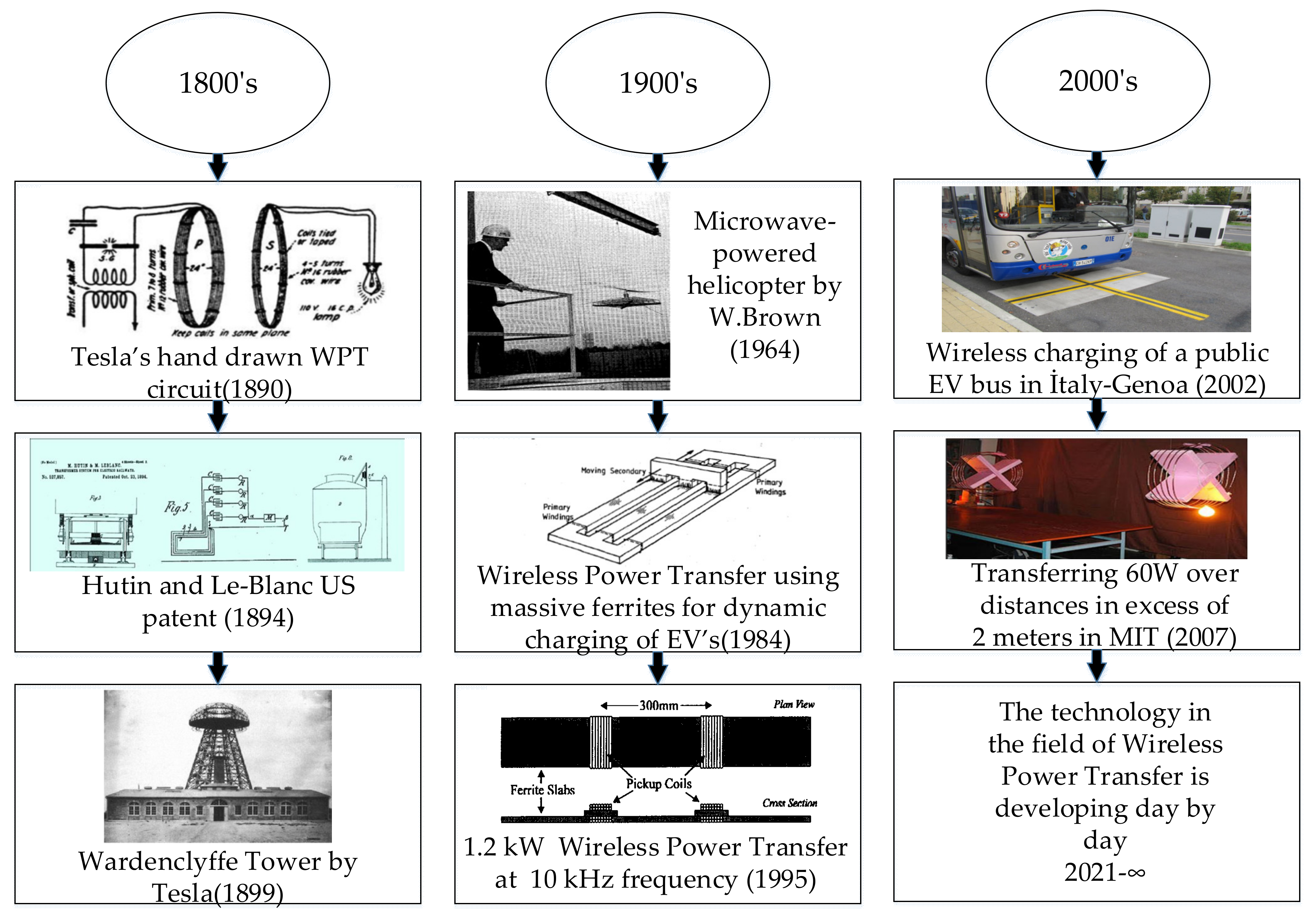
2. History of WPT
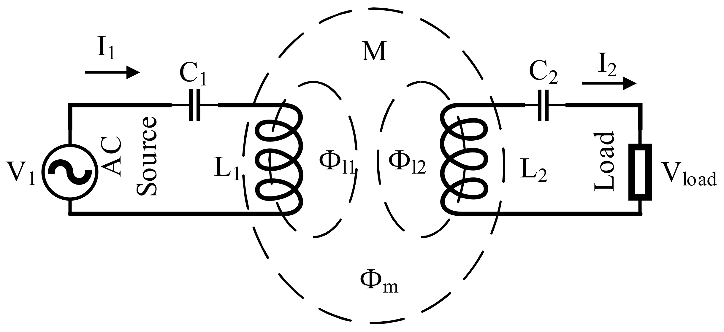
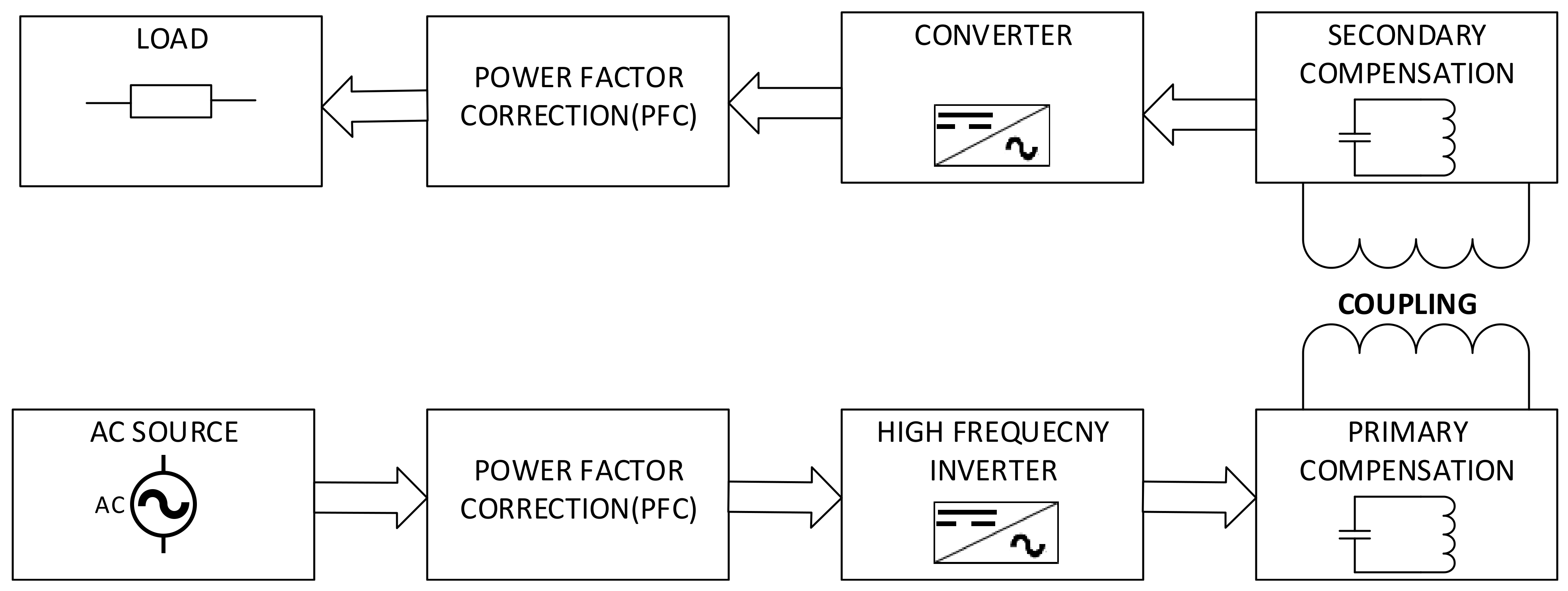
3. Fundamentals of IPT Systems
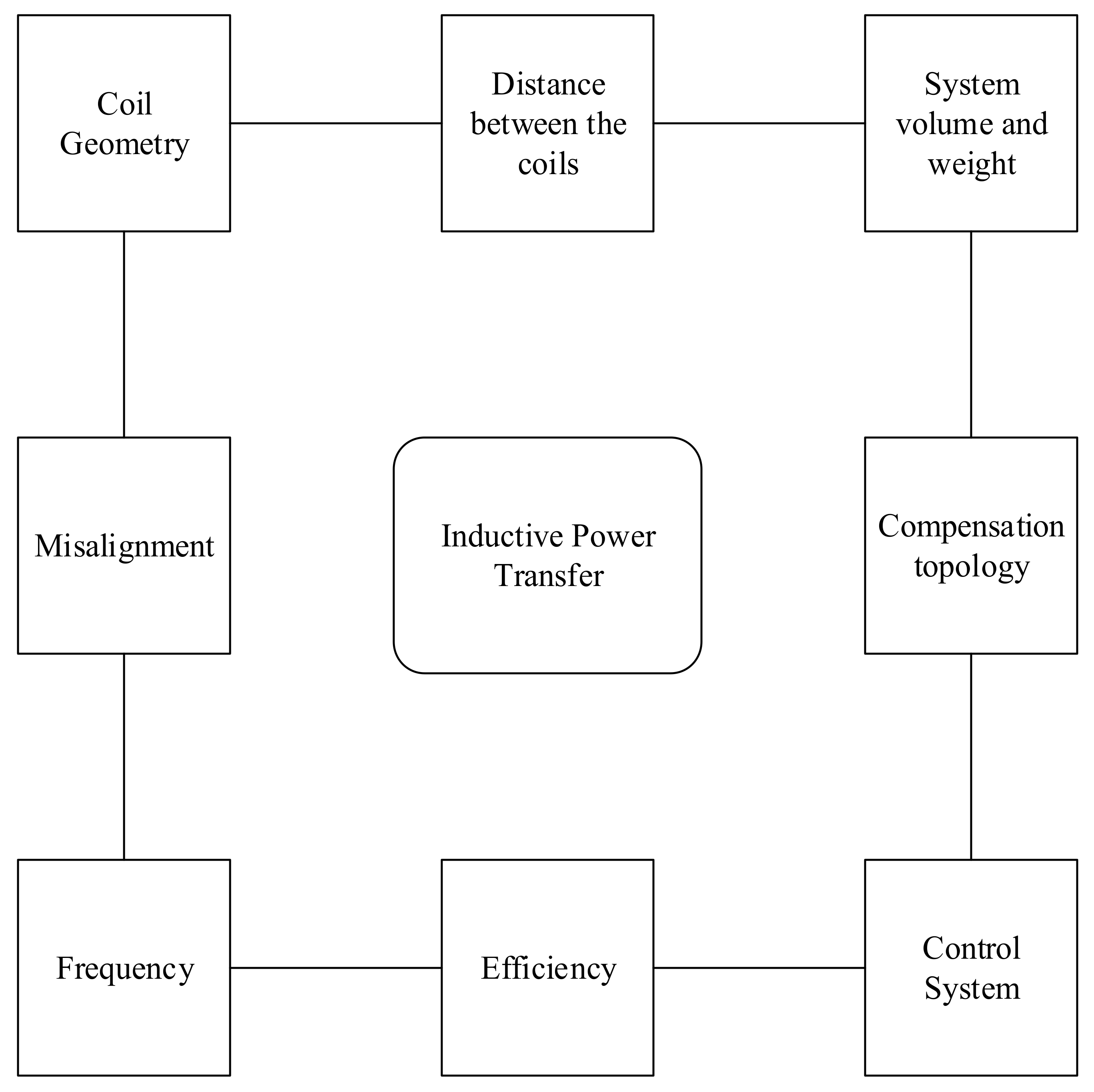
4. Design Considerations in IPT Systems
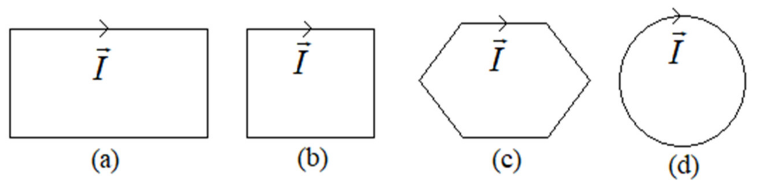
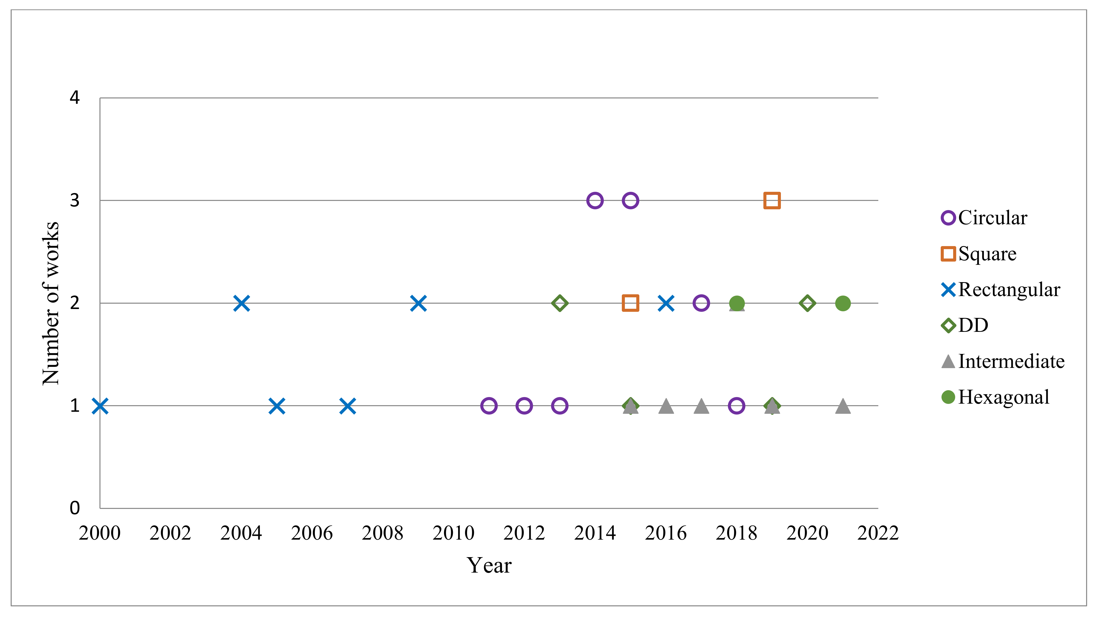
4.1. Coil Design
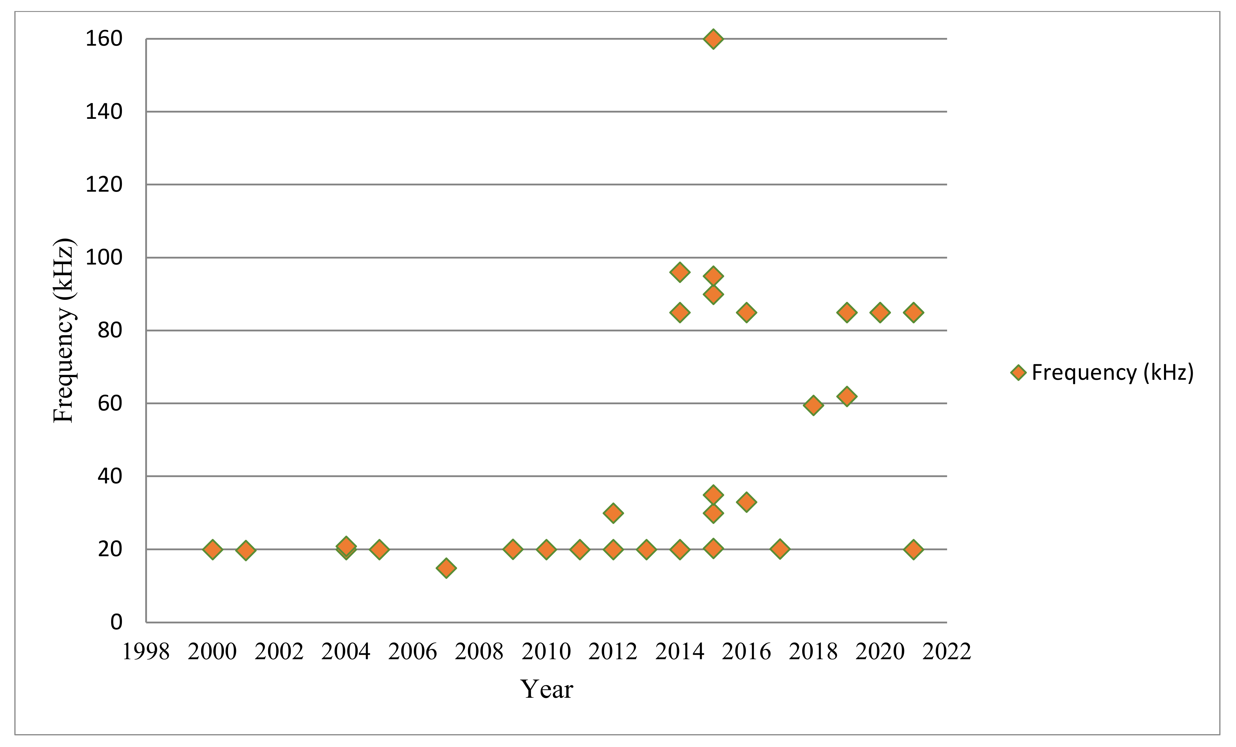
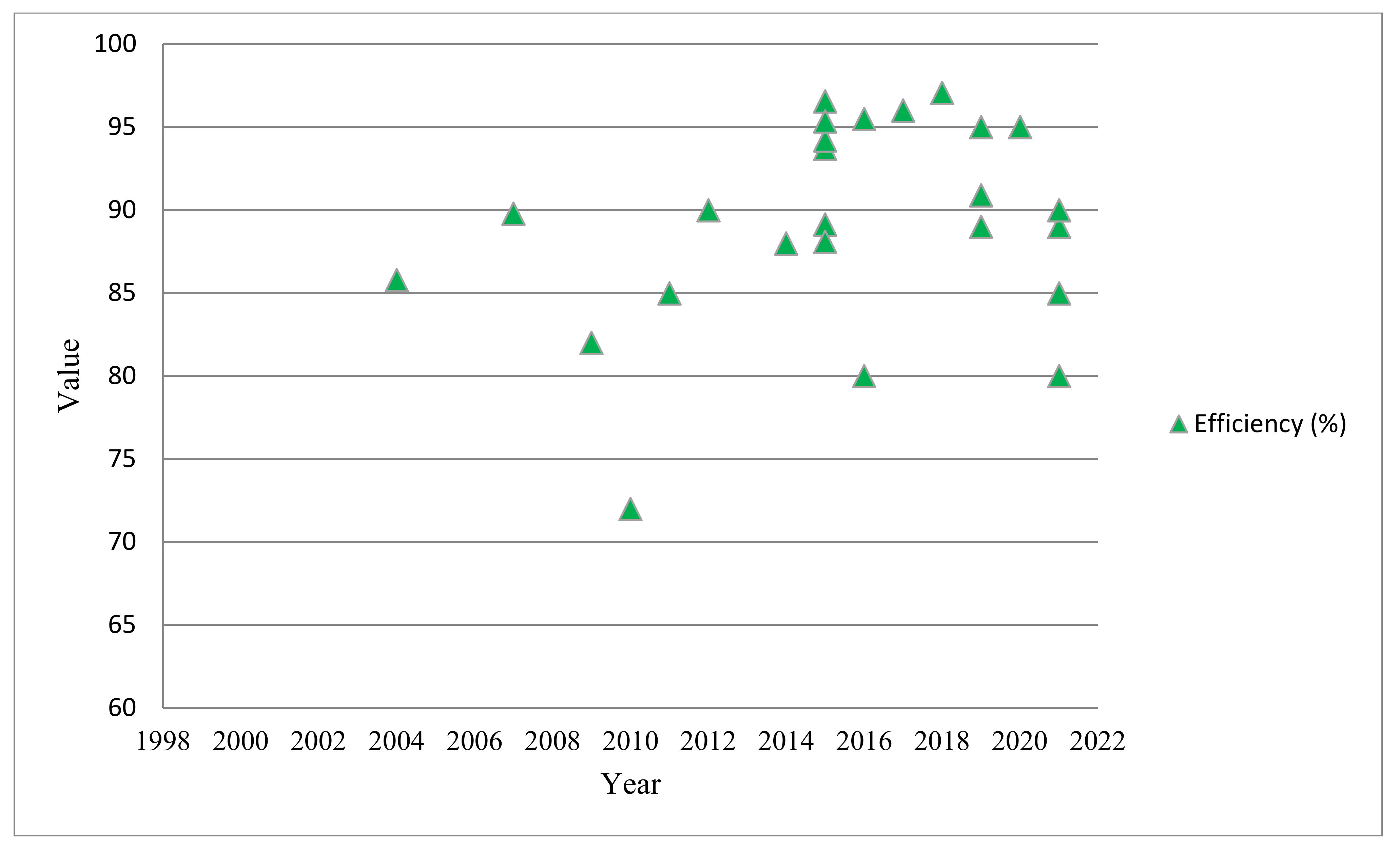
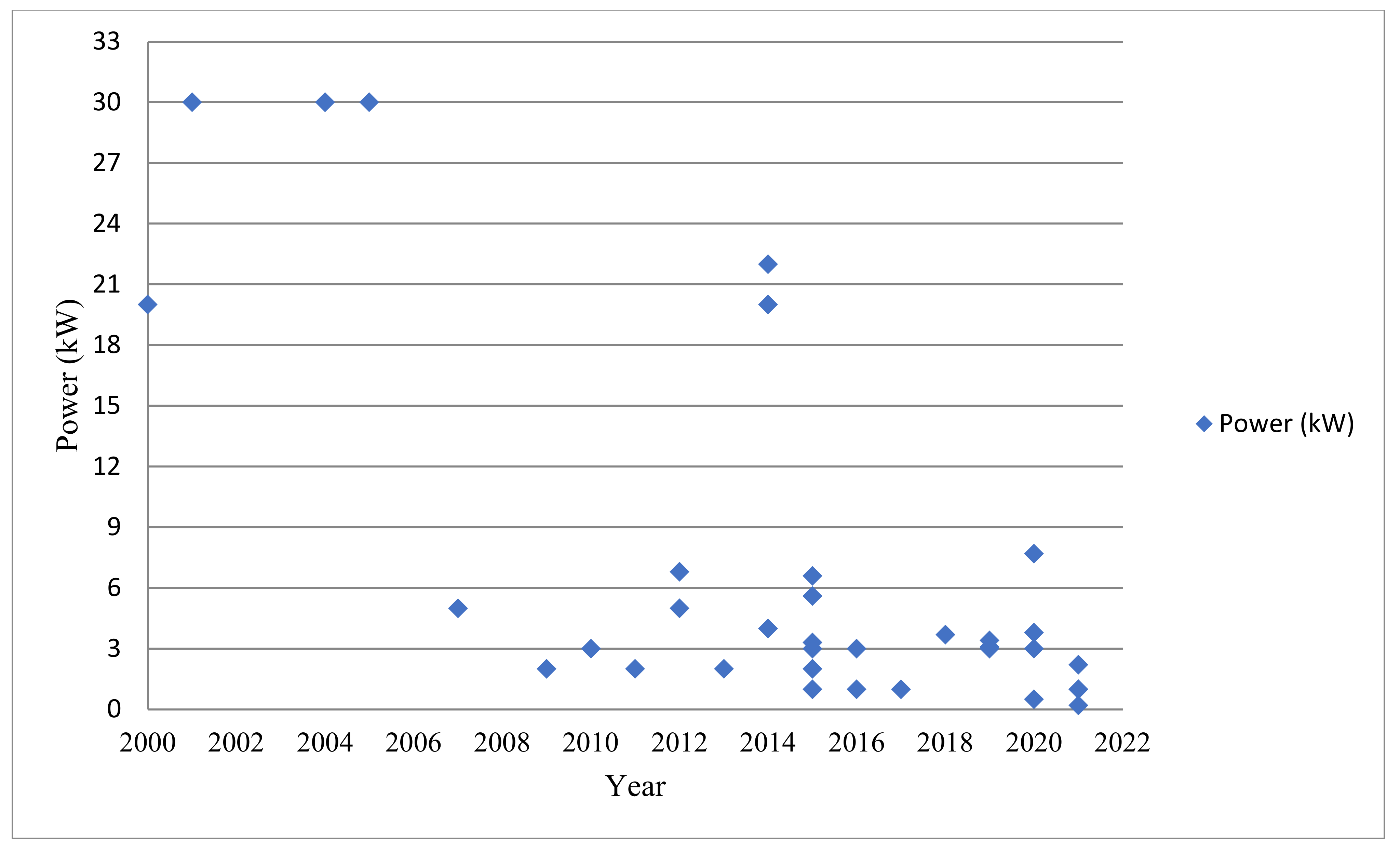
4.2. Operating Frequency, Power and Efficiency
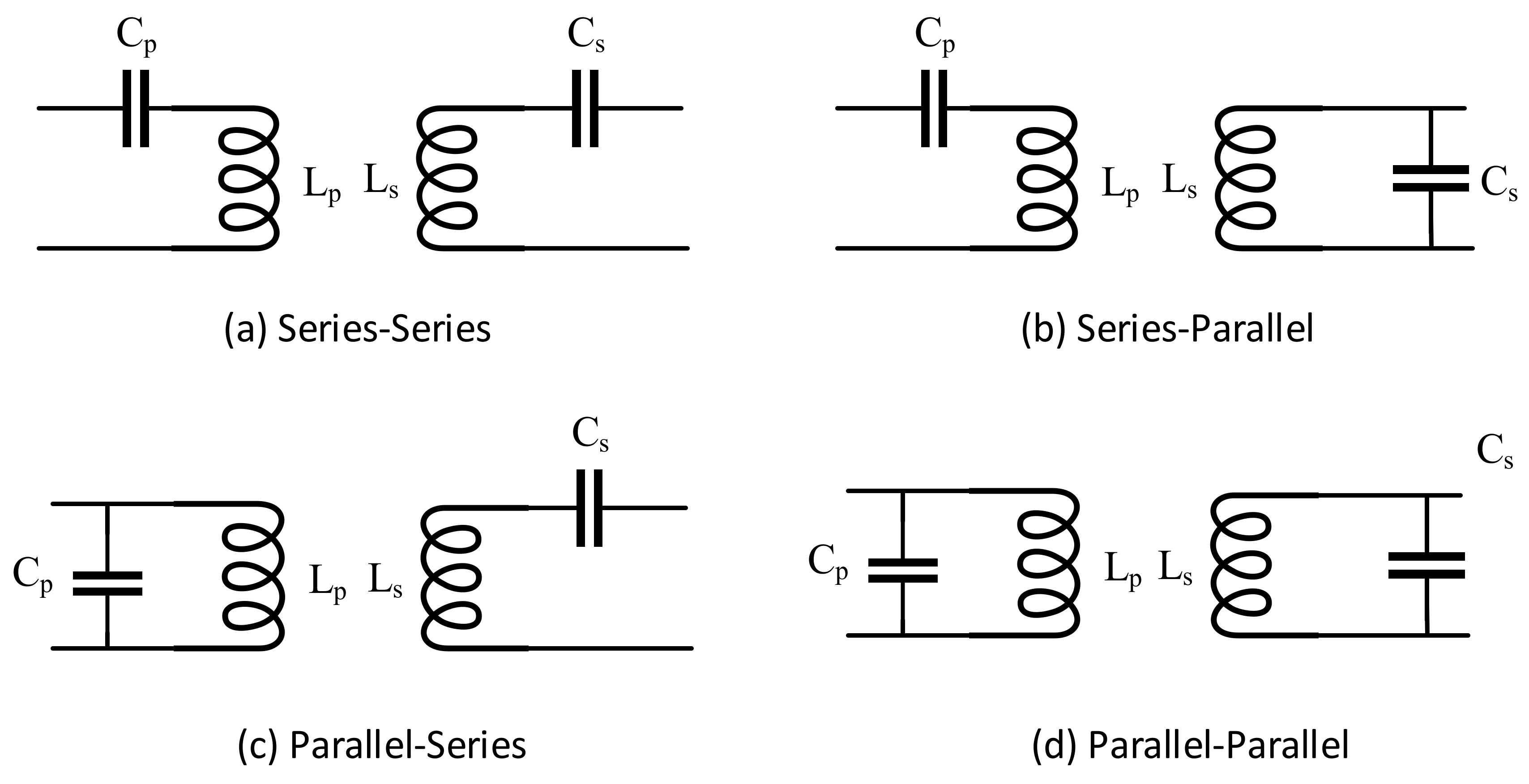
4.3. Compensation Topology
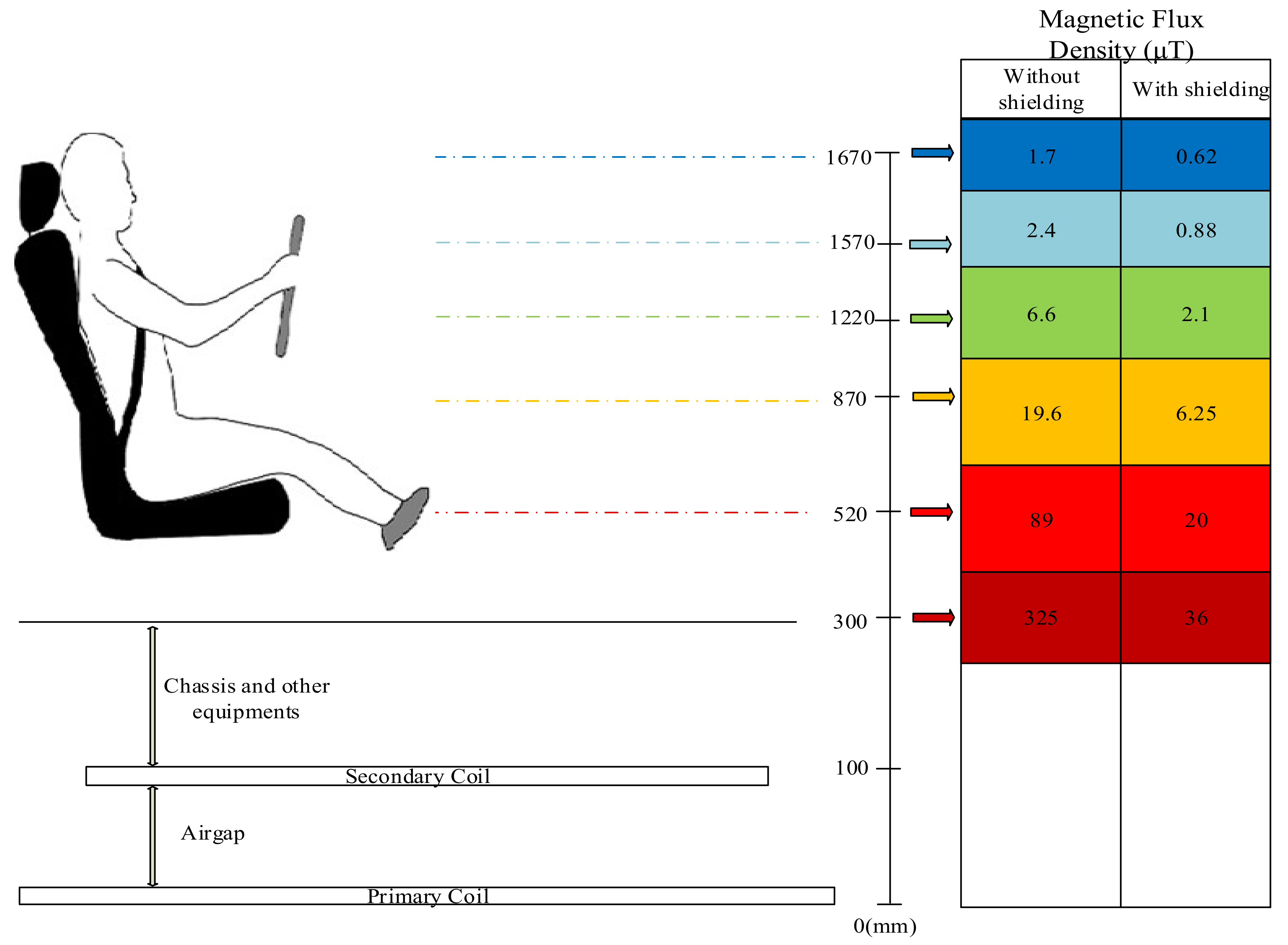
4.4. Health Issues
- -
- IEEE standard for determining the level of human exposure to radio frequency electromagnetic fields. Basic Specifications: 3 kHz to 300 GHz frequency range (2005–2019 versions available) [64];
- -
- ICNIRP Guidelines for time-varying electric and magnetic field exposure limits. Basic Specifications: 1 Hz to 100 kHz frequency range, which means it is for low-frequency applications (LFA) [65];
- -
- ICNIRP Guidelines for time-varying electric and magnetic field exposure limits. Basic Specifications: Frequency range, 100 kHz to 300 GHz, which means it is for high-frequency applications (HFA) [66]
- -
- Canada Environmental and Radiation Health Sciences Directorate (ERHSD) guide for the protection of consumers from radiation. Basic Specifications: 3 kHz–300 GHz frequency range, 2015 [67];
- -
- SAE (Society of Automotive Engineers) J2954 standard is a constantly updated standard for Electric vehicles and Plug-in Hybrid Electric vehicles in the power ranges from 3.7 kW to 22 kW, 2020 [54];
- -
- The guidelines for Wireless Power systems prepared by the Broadband Wireless Forum Japan. It is a standard that can be used for applications operating in the frequency range of 10 kHz to 10 MHz, which was last updated in 2013 by a consortium formed by a group of researchers in 2009 [68].
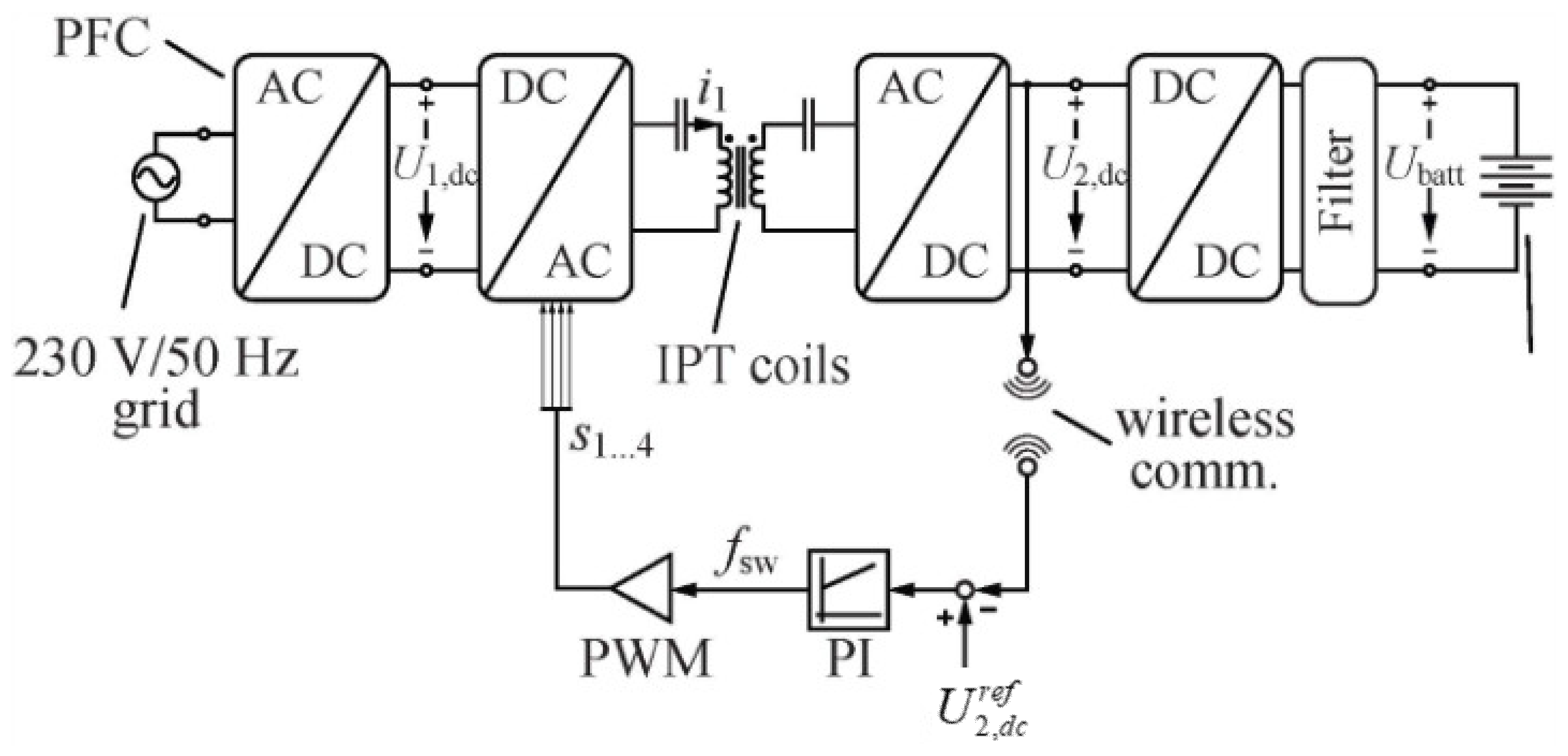
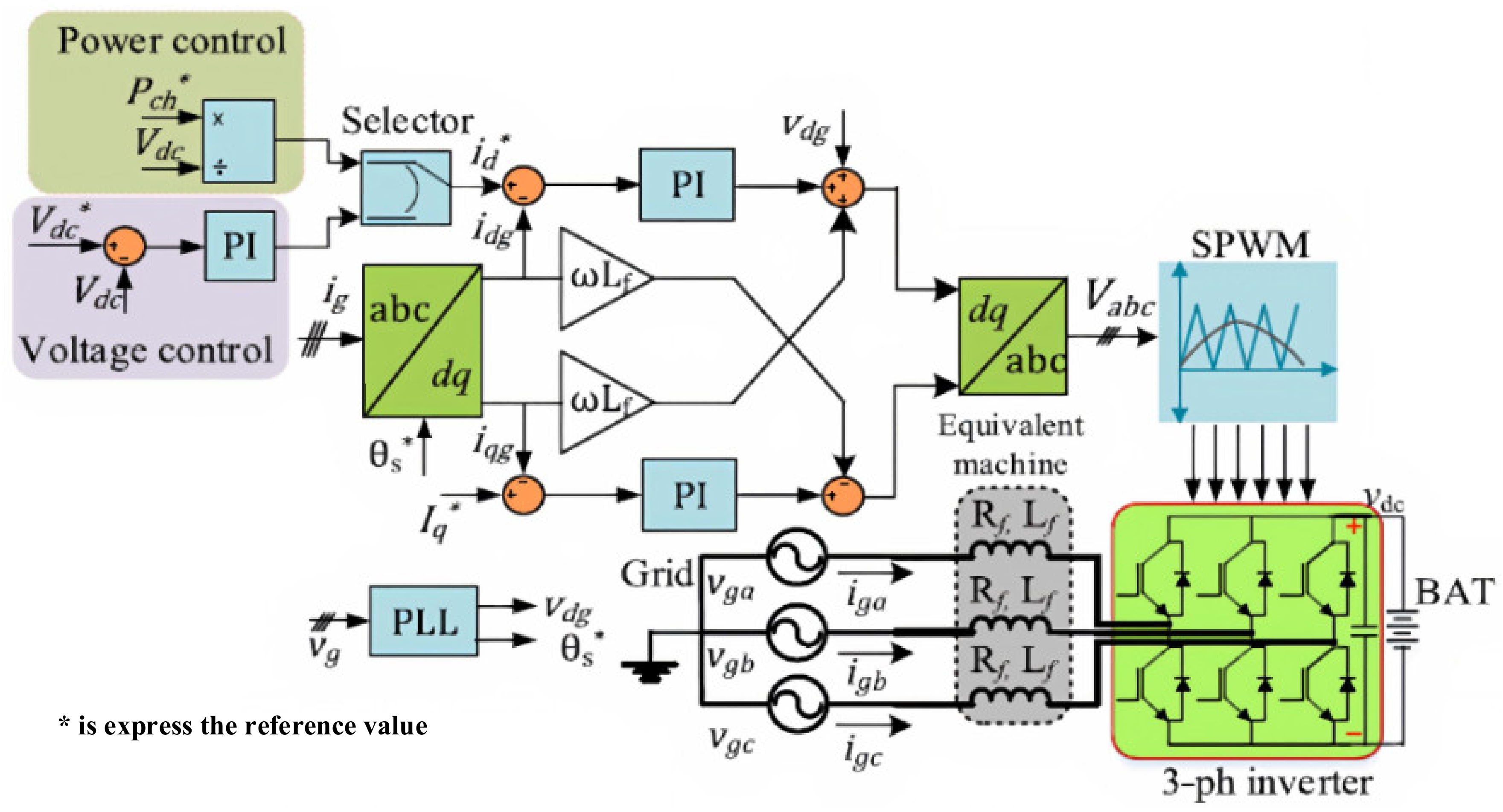
4.5. Control System
4.5.1. Controller Location
4.5.2. Control Variable
- Output (battery) voltage, battery current and SOC;
- Reactive power and WPT network impedance;
- Maximum efficiency.
5. Discussion
- (a)
- High-power transfer with smaller size coils and smaller compensation topologies, which will make the system lighter and lower cost;
- (b)
- The role of the WPT systems in fast and extreme fast charging technologies since the charging time is still a problem for EVs;
- (c)
- The effect of time-varying electric and magnetic field in WPT systems on consumer health need further detail studies and EMC problems should be discussed;
- (d)
- Grid management according to Static and Dynamic WPT systems and Vehicle-to-Grid (V2G) technology through Wireless EV charging;
- (e)
- Modular systems for WPT applications are receiving more attention these days and the power range of this type of applications could be varies from low power to high power;
- (f)
- Electrifying roads are another hot topic for this technology, which is under development in some pilot projects around the world and expect to be commercially available in the near future.
Author Contributions
Funding
Data Availability Statement
Acknowledgments
Conflicts of Interest
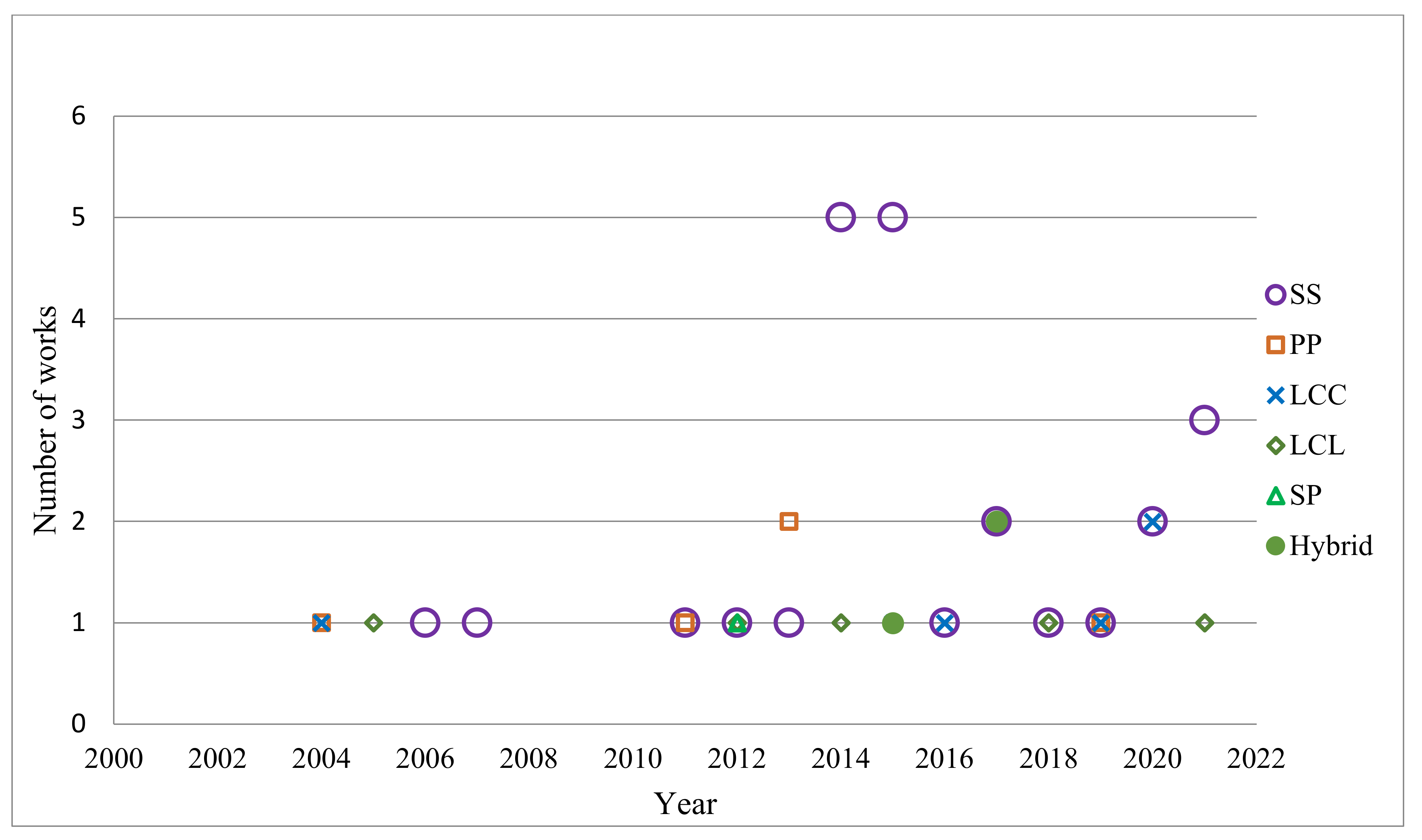
Appendix A

| Work | Year | Frequency (kHz) | Airgap (mm) | Power (kW) | Core | Coil Structure | C.Topology | Efficiency (%) |
|---|---|---|---|---|---|---|---|---|
| [91] | 2000 | 20 | N/A | 20 | N/A | N/A | N/A | N/A |
| [24] | 2001 | 19.7 | 45 | 30 | Yes | Rectangular | N/A | N/A |
| [92] | 2004 | 20 | 45 | 30 | No | Rectangular | PP | N/A |
| [93] | 2004 | 20.9 | 45 | 30 | No | Rectangular | LCL-P | 85.8 |
| [25] | 2005 | 20 | 45 | 30 | No | Rectangular | LCL-P | N/A |
| [1] | 2007 | 14.9 | 200 | 5 | No | Rectangular | SS | 89.8 |
| [23] | 2009 | 20.1 | 150 | 2 | No | Rectangular | SS | 82 |
| [94] | 2010 | 20 | 170 | 3 | N/A | N/A | N/A | 72 |
| [27] | 2011 | 20 | 100 | 2 | Yes | Circular | PP | 85 |
| [95] | 2012 | 20 | 255 | 5 | Yes | Circular | LCL | 90 |
| [96] | 2012 | 30 | N/A | 6.8 | N/A | N/A | SS | N/A |
| [33] | 2013 | 20 | 200 | 2 | Yes | DD, DDQ | PP | N/A |
| [97] | 2014 | 165 | 150 | 4 | No | Circular | SS | N/A |
| [98] | 2014 | 96 | 40 | 4 | Yes | Circular | SS | N/A |
| [99] | 2014 | 20 | N/A | 20 | N/A | N/A | LCL | 88 |
| [100] | 2014 | 85 | N/A | 22 | N/A | N/A | SS | N/A |
| [101] | 2015 | 160 | 203.2 | 1 | No | Square | SS | 93.7 |
| [102] | 2015 | 30 | 150 | 2 | Yes | Circular | SS | 89.15 |
| [103] | 2015 | 35 | 135 | 3 | Yes | Circular | SS | 94.2 |
| [104] | 2015 | 90 | 200 | 3.3 | No | Intermediate | SS | 96.56 |
| [105] | 2015 | 95 | 150 | 5.6 | Yes | DD | LCC | 95.36 |
| [106] | 2015 | 20.3 | 120 | 6.6 | No | Circular | SS | 88.1 |
| [107] | 2015 | N/A | 100 | N/A | No | Circular | SS | 90 |
| [41] | 2016 | 33 | 300 | 1 | No | Intermediate | SS | 80 |
| [108] | 2017 | 85 | 150 | 3 | Yes | Rectangular | LCC | 95.5 |
| [109] | 2017 | 20.15 | 185 | 1 | Yes | Circular | SS | 96 |
| [50] | 2018 | 59.5 | 200 | 3.7 | No | Intermediate | SS | 97.08 |
| [110] | 2019 | 62 | 300 | 3 | Yes | Square | SS | 90.9 |
| [37] | 2019 | 85 | 175 | 3.4 | Yes | DD | PP | 89 |
| [111] | 2019 | 85 | 150 | 3.09 | Yes | Intermediate | LCC | 95 |
| [112] | 2020 | 85 | 150 | 7.7 | No | Rectangular | SS | N/A |
| [113] | 2020 | 85 | 200 | 3 | Yes | BP | Hybrid | 95 |
| [114] | 2020 | 85 | N/A | 3.8 | N/A | Circular | LCL | N/A |
| [115] | 2020 | 85 | N/A | 0.5 | Yes | Circular | LCC | 95 |
| [116] | 2021 | 85 | 175 | 2.2 | Yes | Intermediate | SS | 89 |
| [117] | 2021 | 85 | 150 | 1 | No | Intermediate | LCL | 90 |
| [30] | 2021 | 20 | 100 | 1 | No | Hexagonal | SS | 85 |
| [32] | 2021 | 85 | 100 | 0.2 | No | Hexagonal | SS | 80 |
References
- Villa, J.L.; Lombart, A.; Sanz, J.F.; Sallan, J. Practical Development of a 5 kW ICPT System SS Compensated with a Large Air gap. In Proceedings of the 2007 IEEE International Symposium on Industrial Electronics, Vigo, Spain, 4–7 June 2007; pp. 1219–1223. [Google Scholar]
- Jang, Y.; Jovanovic, M.M. A contactless electrical energy transmission system for portable-telephone battery chargers. IEEE Trans. Ind. Electron. 2003, 50, 520–527. [Google Scholar] [CrossRef] [Green Version]
- Ram Rakhyani, A.K.; Mirabbasi, S.; Chiao, M. Design and Optimization of Resonance-Based Efficient Wireless Power Delivery Systems for Biomedical Implants. IEEE Trans. Biomed. Circuits Syst. 2011, 5, 48–63. [Google Scholar] [CrossRef]
- Ma, H.; Yang, Y.; Qi, N.; Ma, S.; Li, X. Demonstration of a high-efficiency MWPT System for Aerospace. In Proceedings of the 2018 IEEE Wireless Power Transfer Conference (WPTC), Montreal, QC, Canada, 3–7 June 2018; pp. 1–4. [Google Scholar]
- Zhu, D.; Grabham, N.J.; Clare, L.; Stark, B.H.; Beeby, S.P. Inductive power transfer in e-textile applications: Reducing the effects of coil misalignment. In Proceedings of the 2015 IEEE Wireless Power Transfer Conference (WPTC), Boulder, CO, USA, 13–15 May 2015; pp. 1–4. [Google Scholar]
- Sealy, K.D.; Efe, V.; Patterson, S.M.; Bohm, R.J.; Kesler, M.P. Wireless Power Transfer for a Seat-Vest-Helmet System. U.S. Patent US20150115733A1, 30 April 2015. [Google Scholar]
- Mohamed, A.A.S.; Lashway, C.R.; Mohammed, O. Modeling and Feasibility Analysis of Quasi-Dynamic WPT System for EV Applications. IEEE Trans. Transp. Electrif. 2017, 3, 343–353. [Google Scholar] [CrossRef]
- Jang, Y.J.; Jeong, S.; Lee, M.S. Initial Energy Logistics Cost Analysis for Stationary, Quasi-Dynamic, and Dynamic Wireless Charging Public Transportation Systems. Energies 2016, 9, 483. [Google Scholar] [CrossRef] [Green Version]
- Hertz, H.; Mulligan, J.F. Heinrich Rudolf Hertz (1857–1894): A Collection of Articles and Addresses; Garland Pub: New York, NY, USA, 1994. [Google Scholar]
- Massie, W.W.; Underhill, C.R. The future of the wireless art. In Wireless Telegraphy and Telephony; D. Van Nostrand: New York, NY, USA, 1908; pp. 67–71. [Google Scholar]
- Hutin, M.; Leblanc, M. Transformer System for Electric Railways. U.S. Patent 527,857, 23 October 1894. [Google Scholar]
- Brown, W.C. The history of wireless power transmission. Solar Energy 1996, 56, 3–21. [Google Scholar] [CrossRef]
- Abel, E.; Third, S. Contactless power transfer—An exercise in topology. IEEE Trans. Magn. 1984, 20, 1813–1815. [Google Scholar] [CrossRef]
- Delmas, A.; Omeich, M.; Rioux, C. High efficiency inductive energy transfer. In Proceedings of the 7th Pulsed Power Conference, Monterey, CA, USA, 11–14 June 1989; pp. 598–601. [Google Scholar]
- Esser, A. Contactless charging and communication for electric vehicles. IEEE Ind. Appl. Mag. 1995, 1, 4–11. [Google Scholar] [CrossRef]
- Eghtesadi, M. Inductive power transfer to an electric vehicle-analytical model. In Proceedings of the 40th IEEE Conference on Vehicular Technology, Orlando, FL, USA, 6–9 May 1990; pp. 100–104. [Google Scholar]
- Elliott, G.A.J.; Boys, J.T.; Green, A.W. Magnetically coupled systems for power transfer to electric vehicles. In Proceedings of the 1995 International Conference on Power Electronics and Drive Systems (PEDS 95), Singapore, 21–23 February 1995; Volume 2, pp. 797–801. [Google Scholar]
- Kurs, A.; Karalis, A.; Moffatt, R.; Joannopoulos, J.D.; Fisher, P.; Soljacic, M. Wireless Power Transfer via Strongly Coupled Magnetic Resonances. Science 2007, 317, 83–86. [Google Scholar] [CrossRef] [Green Version]
- Kline, M.; Izyumin, I.; Boser, B.; Sanders, S. Capacitive power transfer for contactless charging. In Proceedings of the 2011 Twenty-Sixth Annual IEEE Applied Power Electronics Conference and Exposition (APEC), Fort Worth, TX, USA, 6–11 March 2011; pp. 1398–1404. [Google Scholar] [CrossRef] [Green Version]
- Dai, J.; Ludois, D.C. A Survey of Wireless Power Transfer and a Critical Comparison of Inductive and Capacitive Coupling for Small Gap Applications. IEEE Trans. Power Electron. 2015, 30, 6017–6029. [Google Scholar] [CrossRef]
- Yang, Y.; Cui, J.; Cui, X. Design and Analysis of Magnetic Coils for Optimizing the Coupling Coefficient in an Electric Vehicle Wireless Power Transfer System. Energies 2020, 13, 4143. [Google Scholar] [CrossRef]
- Bosshard, R.; Mühlethaler, J.; Kolar, J.W.; Stevanović, I. Optimized magnetic design for inductive power transfer coils. In Proceedings of the 28th Applied Power Electronics Conference and Exposition (APEC), Long Beach, CA, USA, 17–21 March 2013; pp. 1812–1819. [Google Scholar]
- Sallan, J.; Villa, J.L.; Llombart, A.; ve Sanz, J.F. Optimal design of ICPT systems applied to electric vehicle battery charge. IEEE Trans. Ind. Electron. 2009, 56, 2140–2149. [Google Scholar] [CrossRef]
- Wang, C.-S.; Covic, G.A.; Stielau, O.H. General stability criterions for zero phase angle controlled loosely coupled inductive power transfer systems. In Proceedings of the IECON’01. 27th Annual Conference of the IEEE Industrial Electronics Society (Cat. No.37243), Denver, CO, USA, 29 November–2 December 2001; Volume 2, pp. 1049–1054. [Google Scholar]
- Wang, C.S.; Stielau, O.H.; Covic, G.A. Design considerations for a contactless electric vehicle battery charger. IEEE Trans. Ind. Electron. 2005, 52, 1308–1314. [Google Scholar] [CrossRef]
- Yang, Y.; El Baghdadi, M.; Lan, Y.; Benomar, Y.; Van Mierlo, J.; Hegazy, O. Design Methodology, Modeling, and Comparative Study of Wireless Power Transfer Systems for Electric Vehicles. Energies 2018, 11, 17176. [Google Scholar] [CrossRef] [Green Version]
- Budhia, M.; Covic, G.A.; Boys, J.T. Design and Optimization of Circular Magnetic Structures for Lumped Inductive Power Transfer Systems. IEEE Trans. Power Electron. 2011, 26, 3096–3108. [Google Scholar] [CrossRef]
- Kosesoy, Y.; Aydin, E.; Yildiriz, E.; Aydemir, M.T. Design and Implementation of a 1-kW Wireless Power Transfer System for EV Charging. In Proceedings of the IEEE 13th International Conference on Compatibility, Power Electronics and Power Engineering (CPE-POWERENG), Sonderborg, Denmark, 23–25 April 2019. [Google Scholar]
- Aydin, E.; Kosesoy, Y.; Yildiriz, E.; Aydemir, M.T. Comparison of Hexagonal and Square Coils for Use in Wireless Charging of Electric Vehicle Battery. In Proceedings of the IEEE 2018 International Symposium on Electronics and Telecommunications (ISETC), Timisoara, Romania, 8–9 November 2018. [Google Scholar]
- Aydin, E.; Aydemir, M.T. A 1-kw wireless power transfer system for electric vehicle charging with hexagonal flat spiral coil. Turk. J. Electr. Eng. Comput. Sci. 2021, 29, 2346–2361. [Google Scholar] [CrossRef]
- Tan, P.; Yi, F.; Liu, C.; Guo, Y. Modeling of Mutual Inductance for Hexagonal Coils with Horizontal Misalignment in Wireless Power Transfer. In Proceedings of the IEEE Energy Conversion Congress and Exposition (ECCE), Portland, OR, USA, 23–27 September 2018. [Google Scholar]
- Tan, P.; Peng, T.; Gao, X.; Zhang, B. Flexible Combination and Switching Control for Robust Wireless Power Transfer System with Hexagonal Array Coil. IEEE Trans. Power Electron. 2021, 36, 3868–3882. [Google Scholar] [CrossRef]
- Budhia, M.; Boys, J.T.; Covic, G.A.; Huang, C.-Y. Development of a Single-Sided Flux Magnetic Coupler for Electric Vehicle IPT Charging Systems, Industrial Electronics. IEEE Trans. 2013, 60, 318–328. [Google Scholar]
- Nagendra, G.R.; Covic, G.A.; Boys, J.T. Determining the Physical Size of Inductive Couplers for IPT EV Systems. IEEE J. Emerg. Sel. Top. Power Electron. 2014, 2, 571–583. [Google Scholar] [CrossRef]
- Lin, F.Y.; Zaheer, A.; Budhia, M.; Covic, G.A. Reducing leakage flux in IPT systems by modifying pad ferrite structures. In Proceedings of the IEEE Energy Conversion Congress and Exposition (ECCE), Pittsburgh, PA, USA, 14–18 September 2014; pp. 1770–1777. [Google Scholar]
- Zaheer, A.; Kacprzak, D.; Covic, G.A. A bipolar receiver pad in a lumped IPT system for electric vehicle charging applications. In Proceedings of the IEEE Energy Conversion Congress and Exposition (ECCE), Raleigh, NC, USA, 15–20 September 2012; pp. 283–290. [Google Scholar]
- Pearce, M.G.S.; Covic, G.A.; Boys, J.T. Robust Ferrite-Less Double D Topology for Roadway IPT Applications. IEEE Trans. Power Electron. 2019, 34, 6062–6075. [Google Scholar] [CrossRef]
- Zheng, C.; Ma, H.; Lai, J.S.; Zhang, L. Design Considerations to Reduce Gap Yesiation and Misalignment Effects for the Inductive Power Transfer System. IEEE Trans. Power Electron. 2015, 30, 6108–6119. [Google Scholar] [CrossRef]
- Dang, Z.; Qahouq, J.A.A. Modeling and investigation of magnetic resonance coupled wireless power transfer system with lateral misalignment. In Proceedings of the 2014 IEEE Applied Power Electronics Conference and Exposition—APEC, Fort Worth, TX, USA, 16–20 March 2014. [Google Scholar]
- Choi, S.Y.; Huh, J.; Lee, W.Y.; Rim, C.T. Asymmetric Coil Sets for Wireless Stationary EV Chargers with Large Lateral Tolerance by Dominant Field Analysis. IEEE Trans. Power Electron. 2014, 29, 6406–6420. [Google Scholar] [CrossRef]
- Kalwar, K.A.; Mekhilef, S.; Seyedmahmoudian, M.; Horan, B. Coil Design for High Misalignment Tolerant Inductive Power Transfer System for EV Charging. Energies 2016, 9, 937. [Google Scholar] [CrossRef] [Green Version]
- Sis, S.A.; Orta, E. A Cross-Shape Coil Structure for Use in Wireless Power Applications. Energies 2018, 11, 1094. [Google Scholar] [CrossRef] [Green Version]
- Ahn, D.; Hong, S. A Study on Magnetic Field Repeater in Wireless Power Transfer. IEEE Trans. Ind. Electron. 2013, 60, 360–371. [Google Scholar] [CrossRef]
- Kim, J.; Son, H.; Kim, K.; Park, Y. Efficiency Analysis of Magnetic Resonance Wireless Power Transfer with Intermediate Resonant Coil. IEEE Antennas Wirel. Propag. Lett. 2011, 10, 389–392. [Google Scholar] [CrossRef]
- Lee, C.K.; Zhong, W.X.; Hui, S.Y.R. Effects of Magnetic Coupling of Nonadjacent Resonators on Wireless Power Domino-Resonator Systems. IEEE Trans. Power Electron. 2012, 27, 1905–1916. [Google Scholar] [CrossRef] [Green Version]
- Hatchavanich, N.; Sangswang, A.; Konghirun, M. Effects of Intermediate Coil Position in a Triple-Coil Series-Series Compensation in Wireless Power Transfer. In Proceedings of the IEEE International Symposium on Circuits and Systems (ISCAS), Sapporo, Japan, 26–29 May 2019; pp. 1–5. [Google Scholar]
- Hatchavanich, N.; Sangswang, A.; Konghirun, M. Operational Region of Novel Multi-Coil Series-Series Compensation in Wireless Power Transfer System for Electric Vehicle Applications. In Proceedings of the IEEE International Symposium on Circuits and Systems (ISCAS), Sapporo, Japan, 26–29 May 2019; pp. 1–5. [Google Scholar]
- Moon, S.; Kim, B.; Cho, S.; Ahn, C.; Moon, G. Analysis and Design of a Wireless Power Transfer System with an Intermediate Coil for High Efficiency. IEEE Trans. Ind. Electron. 2014, 61, 5861–5870. [Google Scholar] [CrossRef]
- Marques, E.G.; Marques, C.; Silva, J.V.N.; da Silva, S.V.; Perdigão, M.S.; Mendes, A.M.S. Evaluation of intermediate coils in IPT systems under magnetic coupler displacements. In Proceedings of the IECON 2017—43rd Annual Conference of the IEEE Industrial Electronics Society, Beijing, China, 29 October–1 November 2017; pp. 5342–5347. [Google Scholar] [CrossRef]
- Tran, D.H.; Vu, V.B.; Choi, W. Design of a High-Efficiency Wireless Power Transfer System with Intermediate Coils for the On-Board Chargers of Electric Vehicles. IEEE Trans. Power Electron. 2018, 33, 175–187. [Google Scholar] [CrossRef]
- Xu, H.; Huang, Z.; Yang, Y.; Huang, Z.; Iam, I.-W.; Lam, C.-S. Analysis and Design of Three-Coil Coupler for Inductive Power Transfer System with Automatic Seamless CC-to-CV Charging Capability. IEEE Access 2022, 10, 10139–10148. [Google Scholar] [CrossRef]
- Jeon, S.J.; Seo, D.-W. Effect of Additional Transmitting Coils on Transfer Distance in Multiple-Transmitter Wireless Power Transfer System. IEEE Access 2022, 10, 9174–9183. [Google Scholar] [CrossRef]
- Mohammed, M.H.; Ameen, Y.M.Y.; Mohamed, A.A.S. A Combined Rectangular/Circular Power Pad for Electric Vehicles Wireless Charging. In Proceedings of the 2021 IEEE Green Technologies Conference (GreenTech), Virtual, 7–9 April 2021; pp. 195–200. [Google Scholar]
- SAE (Society of Automotive Engineers). J2954 Standard is a Constantly Updated Standard for Electric Vehicles and Plug-In Hybrid Electric Vehicles in the Power Ranges from 3.7 kW to 22 kW; SAE: Atlanta, GA, USA, 2020. [Google Scholar]
- Morris, K. Highly Resonant Wireless Power Transfer: Safe, Efficient, and over Distance; Witricity Co.: Watertown, MA, USA, 2017. [Google Scholar]
- Zhang, W.; Mi, C.C. Compensation Topologies of High-Power Wireless Power Transfer Systems. IEEE Trans. Veh. Technol. 2016, 65, 4768–4778. [Google Scholar] [CrossRef]
- Moradewicz, A.J.; Kazmierkowski, M.P. Contactless Energy Transfer System With FPGA-Controlled Resonant Converter. IEEE Trans. Ind. Electron. 2010, 57, 3181–3190. [Google Scholar] [CrossRef]
- Shevchenko, V.; Husev, O.; Strzelecki, R.; Pakhaliuk, B.; Poliakov, N.; Strzelecka, N. Compensation Topologies in IPT Systems: Standards, Requirements, Classification, Analysis, Comparison and Application. IEEE Access 2019, 7, 120559–120580. [Google Scholar] [CrossRef]
- Wang, Y.; Yao, Y.; Liu, X.; Xu, D.; Cai, L. An LC/S Compensation Topology and Coil Design Technique for Wireless Power Transfer. IEEE Trans. Power Electron. 2018, 33, 2007–2025. [Google Scholar] [CrossRef]
- Houran, A.M.; Yang, X.; Chen, W. Magnetically Coupled Resonance WPT: Review of Compensation Topologies, Resonator Structures with Misalignment, and EMI Diagnostics. Electronics 2018, 11, 22. [Google Scholar] [CrossRef] [Green Version]
- Samanta, S.; Rathore, A.K. A New Current-Fed CLC Transmitter and LC Receiver Topology for Inductive Wireless Power Transfer Application: Analysis, Design, and Experimental Results. IEEE Trans. Transp. Electrif. 2015, 1, 357–368. [Google Scholar] [CrossRef]
- Wang, Y.; Yao, Y.; Liu, X.; Xu, D. S/CLC Compensation Topology Analysis and Circular Coil Design for Wireless Power Transfer. IEEE Trans. Transp. Electrif. 2017, 3, 496–507. [Google Scholar] [CrossRef]
- Chen, Y.; Kou, Z.; Zhang, Y.; He, Z.; Mai, R.; Cao, G. Hybrid Topology With Configurable Charge Current and Charge Voltage Output-Based WPT Charger for Massive Electric Bicycles. IEEE J. Emerg. Select. Top. Power Electron. 2018, 6, 1581–1594. [Google Scholar] [CrossRef]
- IEEE Std C95; IEEE Standard for Safety Levels with Respect to Human Exposure to Radio Frequency Electromagnetic Fields, 3 kHz to 300 GHz Amendment. IEEE: New York, NY, USA, 2005; pp. 1–9.
- ICNIRP. Guidelines for limiting exposure to time-Yesying electric and magnetic fields (1 Hz–100 kHz). Health Phys. 2010, 99, 818–836. [Google Scholar] [CrossRef]
- International Commission on Non-Ionizing Radiation Protection. ICNIRP statement on the Guidelines for limiting exposure to time-Yesying electric, magnetic, and electromagnetic fields (up to 300 GHz). Health Phys. 2009, 97, 257–258. [Google Scholar] [CrossRef]
- Canada Environmental and Radiation Health Sciences Directorate (ERHSD). Guide for the Protection of Consumers from Radiation, Basic Specifications: 3 KHZ—300 GHz; Canada Environmental and Radiation Health Sciences Directorate: Ottawa, ON, Canada, 2015.
- Broadband Wireless Forum. Guidelines for the Use of Wireless Power Transmission Technologies, Version 1.0; Broadband Wireless Forum: London, UK, 2007. [Google Scholar]
- Obayashi, S.; Tsukahara, H. EMC issues on wireless power transfer. In Proceedings of the 2014 International Symposium on Electromagnetic Compatibility, Tokyo, Japan, 4–8 August 2014; pp. 601–604. [Google Scholar]
- Zhu, G.; Lorenz, R.D. Achieving low magnetic flux density and low electric field intensity for an inductive wireless power transfer system. In Proceedings of the IEEE Energy Conversion Congress and Exposition (ECCE), Cincinnati, OH, USA, 16–18 February 2017. [Google Scholar]
- Mohamed, C.; Guillaume, V.; Alexandru, T. Compliance Assessment of Human Body Exposure to Wireless Power Systems. In Proceedings of the 2nd World Congress on Electrical Engineering and Computer Systems and Science (EECSS’16), Orleans, ON, Canada, 16–17 August 2016. [Google Scholar]
- Son, S.; Woo, S.; Kim, H.; Ahn, J.; Huh, S.; Lee, S.; Ahn, S. Shielding Sensor Coil to Reduce the Leakage Magnetic Field and Detect the Receiver Position in Wireless Power Transfer System for Electric Vehicle. Energies 2022, 15, 2493. [Google Scholar] [CrossRef]
- Lee, S.; Lorenz, R.D. Development and validation of model for 95% efficiency, 220 W wireless power transfer over a 30 cm air-gap. In Proceedings of the IEEE Energy Conversion Congress and Exposition, Atlanta, GA, USA, 12–16 September 2010. [Google Scholar]
- Chiang, C. Wireless charging system with magnetic field shaping for electric vehicles. In Proceedings of the the World Electric Vehicle Symposium and Exhibition (EVS27), Barcelona, Spain, 17–20 November 2013; pp. 1–5. [Google Scholar]
- Wang, Z.; Wei, X. Design Considerations for Wireless Charging Systems with an Analysis of Batteries. Energies 2015, 8, 10664–10683. [Google Scholar] [CrossRef] [Green Version]
- Bosshard, R.; Badstubner, U.; Kolar, J.W.; Stevanovic, I. Comparative evaluation of control methods for inductive power transfer. In Proceedings of the 2012 International Conference on Renewable Energy Research and Applications (ICRERA), Nagasaki, Japan, 11–14 November 2012; pp. 1–6. [Google Scholar]
- Bosshard, R.; Kolar, J.W.; Wunsch, B. Control method for inductivepower transfer with high partial-load efficiency and resonance tracking. In Proceedings of the 2014 International Power Electronics Conference (IPEC-Hiroshima 2014-ECCE ASIA), Hiroshima, Japan, 18–21 May 2014; pp. 2167–2174. [Google Scholar]
- Nguyen, B.X.; Vilathgamuwa, D.M.; Foo, G.H.B.; Wang, P.; Ong, A.; Madawala, U.K.; Nguyen, T.D. An efficiency optimization schemefor bidirectional inductive power transfer systems. IEEE Trans. Power Electron. 2014, 30, 6310–6319. [Google Scholar] [CrossRef]
- Colak, K.; Asa, E.; Bojarski, L.M.; Czarkowski, D.; Onar, O.C. A novelphase-shift control of semibridgeless active rectifier for wireless powertransfer. IEEE Trans. Power Electron. 2015, 30, 6288–6297. [Google Scholar] [CrossRef]
- Li, K.; Zhao, H.; Liu, Q.; Shi, Y.; Wang, C.; Zhang, P.; Wang, L. Design of novel coil structure for wireless power transfer system supporting multi-load and 2-D free-positioning. Electr. Eng. 2021, 103, 2009–2020. [Google Scholar] [CrossRef]
- Yeo, T.-D.; Kwon, D.; Khang, S.-T.; Yu, Y.-W. Design of maxi-mum efficiency tracking control scheme for closed-loop wireless powercharging system employing series resonant tank. IEEE Trans. Power Electron. 2016, 32, 471–478. [Google Scholar] [CrossRef]
- Patil, D.; Mcdonough, M.K.; Miller, J.M.; Fahimi, B.; Balsara, P.T. Wireless power transfer for vehicular applications: Overviewand challenges. IEEE Trans. Transp. Electrif. 2017, 4, 3–37. [Google Scholar] [CrossRef]
- Dai, X.; Li, X.; Li, Y.; Hu, A.P. Maximum efficiency trackingfor wireless power transfer systems with dynamic coupling coefficientestimation. IEEE Trans. Power Electron. 2017, 33, 5005–5015. [Google Scholar] [CrossRef]
- Li, Y.; Hu, J.; Chen, F.; Li, Z.; He, Z.; Mai, R. Dual-phase-shift controlscheme with current-stress and efficiency optimization for wirelesspower transfer systems. IEEE Trans. Circuits Syst. Regul. Pap. 2018, 65, 3110–3121. [Google Scholar] [CrossRef]
- Lee, W.; Lee, W.; Ahn, D. Maximum Efficiency Conditions Satisfying Power Regulation Constraints in Multiple-Receivers Wireless Power Transfer. Energies 2022, 15, 3840. [Google Scholar] [CrossRef]
- Sun, L.; Tang, H.; Zhang, Y. Determining the Frequency for Load-Independent Output Current in Three-Coil Wireless Power Transfer System. Energies 2015, 8, 9719–9730. [Google Scholar] [CrossRef] [Green Version]
- Gao, Y.; Farley, K.B.; Tse, Z.T.H. A Uniform Voltage Gain Control for Alignment Robustness in Wireless EV Charging. Energies 2015, 8, 8355–8370. [Google Scholar] [CrossRef] [Green Version]
- Mai, R.; Liu, Y.; Li, Y.; Yue, P.; Cao, G.; He, Z. An Active-Rectifier-Based Maximum Efficiency Tracking Method Using an Additional Measurement Coil for Wireless Power Transfer. IEEE Trans. Power Electron. 2018, 33, 716–728. [Google Scholar] [CrossRef]
- Feng, H.; Tavakoli, R.; Onar, O.C.; Pantic, Z. Advances in High-Power Wireless Charging Systems: Overview and Design Considera-tions. IEEE Trans. Transp. Electrif. 2020, 6, 886–919. [Google Scholar] [CrossRef]
- Metwly, M.Y.; Abdel-Majeed, M.S.; Abdel-Khalik, A.S.; Hamdy, R.A.; Hamad, M.S.; Ahmed, S. A Review of Integrated On-Board EV Battery Chargers: Advanced Topologies, Recent Developments and Optimal Selection of FSCW Slot/Pole Combination. IEEE Access 2020, 8, 85216–85242. [Google Scholar] [CrossRef]
- Wang, C.-S.; Stielau, O.H.; Covic, G.A. Load models and their application in the design of loosely coupled inductive power transfer systems. In Proceedings of the PowerCon 2000, International Conference on Power System Technology, (Cat. No. 00EX409), Perth, WA, Australia, 4–8 December 2000; Volume 2, pp. 1053–1058. [Google Scholar]
- Wang, C.-S.; Covic, G.A.; Stielau, O.H. Power transfer capability and bifurcation phenomena of loosely coupled inductive power transfer systems. IEEE Trans. Ind. Electron. 2004, 51, 148–157. [Google Scholar] [CrossRef]
- Wang, C.-S.; Covic, G.A.; Stielau, O.H. Investigating an LCL load resonant inverter for inductive power transfer applications. IEEE Trans. Power Electron. 2004, 19, 995–1002. [Google Scholar] [CrossRef]
- Lee, S.; Huh, J.; Park, C.; Choi, N.; Cho, G.; Rim, C. On-Line Electric Vehicle using inductive power transfer system. In Proceedings of the 2010 IEEE Energy Conversion Congress and Exposition, Atlanta, GA, USA, 12–16 September 2010; pp. 1598–1601. [Google Scholar]
- Wu, H.H.; Gilchrist, A.; Sealy, K.D.; Bronson, D. A High Efficiency 5 kW Inductive Charger for EVs Using Dual Side Control. IEEE Trans. Ind. Inform. 2012, 8, 585–595. [Google Scholar] [CrossRef] [Green Version]
- Bac, N.X.; Vilathgamuwa, D.M.; Madawala, U.K. A matrix converter based Inductive Power Transfer system. In Proceedings of the 2012 10th International Power & Energy Conference (IPEC), Ho Chi Minh City, Vietnam, 12–14 December 2012; pp. 509–514. [Google Scholar]
- Huang, Z.; Wong, C.; Tse, C.K. Design methodology of a series-series inductive power transfer system for electric vehicle battery charger application. In Proceedings of the 2014 IEEE Energy Conversion Congress and Exposition (ECCE), Pitsburgh, PA, USA, 14–18 September 2014; pp. 1778–1782. [Google Scholar]
- Chen, R.; Zheng, C.; Zahid, Z.U.; Faraci, E.; Yu, W.; Lai, J.S.; Senesky, M.; Anderson, D.; Lisi, G. Analysis and parameters optimization of a contactless IPT system for EV charger. In Proceedings of the 2014 IEEE Applied Power Electronics Conference and Exposition—APEC, Fort Worth, TX, USA, 16–20 March 2014; pp. 1654–1661. [Google Scholar]
- Rahnamaee, H.R.; Madawala, U.K.; Thrimawithana, D.J. A multi-level converter for high power-high frequency IPT systems. In Proceedings of the 2014 IEEE 5th International Symposium on Power Electronics for Distributed Generation Systems (PEDG), Galway, Ireland, 24–27 June 2014; pp. 1–6. [Google Scholar]
- Schumann, P.; Blum, O.; Eckhardt, J.; Henkel, A. High efficient, compact vehicle power electronics for 22kW inductive charging. In Proceedings of the 2014 4th International Electric Drives Production Conference (EDPC), Nuremberg, Germany, 30 September–1 October 2014; pp. 1–5. [Google Scholar]
- Asa, E.; Colak, K.; Bojarski, M.; Czarkowski, D. A novel multi-level phase-controlled resonant inverter with common mode capacitor for wireless EV chargers. In Proceedings of the 2015 IEEE Transportation Electrification Conference and Expo (ITEC), Dearborn, MI, USA, 14–17 June 2015; pp. 1–6. [Google Scholar]
- Ibrahim, M.; Pichon, L.; Bernard, L.; Razek, A.; Houivet, J.; Cayol, O. Advanced Modeling of a 2-kW Series–Series Resonating Inductive Charger for Real Electric Vehicle. IEEE Trans. Veh. Technol. 2015, 64, 421–430. [Google Scholar] [CrossRef]
- Diekhans, T.; De Doncker, R.W. A Dual-Side Controlled Inductive Power Transfer System Optimized for Large Coupling Factor Variations and Partial Load. IEEE Trans. Power Electron. 2015, 30, 6320–6328. [Google Scholar] [CrossRef]
- Moon, S.; Moon, G.W. Wireless Power Transfer System with an Asymmetric Four-Coil Resonator for Electric Vehicle Battery Chargers. IEEE Trans. Power Electron. 2015, 31, 6844–6854. [Google Scholar]
- Deng, J.; Li, W.; Nguyen, T.D.; Li, S.; Mi, C.C. Compact and Efficient Bipolar Coupler for Wireless Power Chargers: Design and Analysis. IEEE Trans. Power Electron. 2015, 30, 6130–6140. [Google Scholar] [CrossRef]
- Lee, J.Y.; Han, B.M. A Bidirectional Wireless Power Transfer EV Charger Using Self-Resonant PWM. IEEE Trans. Power Electron. 2015, 30, 1784–1787. [Google Scholar] [CrossRef]
- Agcal, A.; Bekiroglu, N.; Ozcira, S. Examination of Efficiency Based on Air Gap and Characteristic Impedance Variations for Magnetic Resonance Coupling Wireless Energy Transfer. J. Magn. 2015, 20, 57–61. [Google Scholar] [CrossRef] [Green Version]
- Kan, T.; Nguyen, T.D.; Wjite, J.C.; Malhan, R.K.; Mi, C.C. A New Integration Method for an Electric Vehicle Wireless Charging System Using LCC Compensation Topology. IEEE Trans. Power Electron. 2017, 3, 1638–1650. [Google Scholar] [CrossRef]
- Kim, H.; Song, C.; Kim, D.; Jung, D.H.; Kim, I.; Kim, Y.; Kim, J.; Ahn, S.; Kim, J. Coil Design and Measurements of Automotive Magnetic Resonant Wireless Charging System for High-Efficiency and Low Magnetic Field Leakage. IEEE Trans. Microw. Theory Tech. 2017, 64, 383–400. [Google Scholar] [CrossRef]
- Lu, W.; Dong, Y.; Shen, J.; Chen, X. Implementation of High-Power & Low-Frequency Resonant Wireless Power Transfer Charging System for Electric Vehicles. In Proceedings of the IEEE 10th International Symposium on Power Electronics for Distributed Generation Systems (PEDG), Xi’an, China, 3–6 June 2019. [Google Scholar]
- Kan, T.; Lu, F.; Nguyen, T.; Mercier, P.P.; Mi, C.C. Integrated Coil Design for EV Wireless Charging Systems Using LCC Compensation Topology. IEEE Trans. Power Electron. 2018, 33, 9231–9241. [Google Scholar] [CrossRef]
- Grazian, F.; Shi, W.; Soeiro, T.B.; Dong, J.; van Duijsen, P.; Bauer, P. Compensation Network for a 7.7 kW Wireless Charging System that Uses Standardized Coils. In Proceedings of the 2020 IEEE International Symposium on Circuits and Systems (ISCAS), Seville, Spain, 12–14 October 2020; pp. 1–5. [Google Scholar]
- Zhou, J.; Yao, P.; Guo, K.; Cao, P.; Zhang, Y.; Ma, H. A Heterogeneous Inductive Power Transfer System for Electric Vehicles with Spontaneous Constant Current and Constant Voltage Output Features. Electronics 2020, 9, 1978. [Google Scholar] [CrossRef]
- Ruddell, S.; Madawala, U.K.; Thrimawithana, D.J. A Wireless EV Charging Topology With Integrated Energy Storage. IEEE Trans. Power Electron. 2020, 35, 8965–8972. [Google Scholar] [CrossRef]
- Ramezani, A.; Narimani, M. Optimized Electric Vehicle Wireless Chargers with Reduced Output Voltage Sensitivity to Misalignment. IEEE J. Emerg. Sel. Top. Power Electron. 2020, 8, 3569–3581. [Google Scholar] [CrossRef]
- Marques, E.G.; Mendes, A.M.S.; Perdigão, M.S.; Costa, V.S. Design Methodology of a Three Coil IPT System with Parameters Identification for EVs. IEEE Trans. Veh. Technol. 2021, 70, 7509–7521. [Google Scholar] [CrossRef]
- Zhang, P.; Saeedifard, M.; Onar, O.C.; Yang, Q.; Cai, C. A Field Enhancement Integration Design Featuring Misalignment Tolerance for Wireless EV Charging Using LCL Topology. IEEE Trans. Power Electron. 2021, 36, 3852–3867. [Google Scholar] [CrossRef]


| Coil Shape | Parameter | Dimensions (mm) | Coupling Coefficient (k) |
|---|---|---|---|
| Circular | radius | 112 | 0.269 |
| Hexagonal | length of side | 124 | 0.249 |
| Rectangular | Length × width | 141 × 282 | 0.209 |
| Square | length of side | 200 | 0.194 |
| Topology | Primary Compensation Capacitor |
|---|---|
| SS | |
| SP | |
| PS | |
| PP |
| Health Standard | Frequency Range |
|---|---|
| IEEE | 3 kHz–3 GHz |
| ICNIRP for LFA | 1 Hz–100 kHz |
| ICNIRP for HFA | 100 kHz–300 GHz |
| ERHSD | 3 kHz–300 GHz |
| SAE | 80 kHz–90 kHz. |
| Wireless forum of JAPAN | 10 kHz–10 MHz |
Publisher’s Note: MDPI stays neutral with regard to jurisdictional claims in published maps and institutional affiliations. |
© 2022 by the authors. Licensee MDPI, Basel, Switzerland. This article is an open access article distributed under the terms and conditions of the Creative Commons Attribution (CC BY) license (https://creativecommons.org/licenses/by/4.0/).
Share and Cite
Aydin, E.; Aydemir, M.T.; Aksoz, A.; El Baghdadi, M.; Hegazy, O. Inductive Power Transfer for Electric Vehicle Charging Applications: A Comprehensive Review. Energies 2022, 15, 4962. https://doi.org/10.3390/en15144962
Aydin E, Aydemir MT, Aksoz A, El Baghdadi M, Hegazy O. Inductive Power Transfer for Electric Vehicle Charging Applications: A Comprehensive Review. Energies. 2022; 15(14):4962. https://doi.org/10.3390/en15144962
Chicago/Turabian StyleAydin, Emrullah, Mehmet Timur Aydemir, Ahmet Aksoz, Mohamed El Baghdadi, and Omar Hegazy. 2022. "Inductive Power Transfer for Electric Vehicle Charging Applications: A Comprehensive Review" Energies 15, no. 14: 4962. https://doi.org/10.3390/en15144962