Review

Integration of Switched Reluctance Generator in a Wind Energy Conversion System: An Overview of the State of the Art and Challenges

1
LATIS-Laboratory of Advanced Technology and Intelligent Systems, Ecole Nationale d’Ingénieurs de Sousse, Université de Sousse, Sousse 4023, Tunisia
2
Institute for Systems and Computer Engineering, Technology and Science (INESC TEC), Faculty of Engineering, University of Porto, 4200-465 Porto, Portugal
*
Author to whom correspondence should be addressed.
Energies 2022, 15(13), 4743; https://doi.org/10.3390/en15134743
Submission received: 6 June 2022 / Revised: 24 June 2022 / Accepted: 27 June 2022 / Published: 28 June 2022
(This article belongs to the Special Issue Wind Energy Technologies Development)

Abstract

:
This paper presents a technical overview for Switched Reluctance Generators (SRG) in Wind Energy Conversion System (WECS) applications. Several topics are discussed, such as the main structures and topologies for SRG converters in WECS, and the optimization control methods to improve the operational efficiency of SRGs in wind power generation systems. A comprehensive overview including the main characteristics of each SRG converter topology and control techniques were discussed. The analysis presented can also serve as a foundation for more advanced versions of SRG control techniques, providing a necessary basis to spur more and, above all, motivate the younger researchers to study magnetless electric machines, and pave the way for higher growth of wind generators based on SRGs.

1. Introduction

Since prehistoric times, energy has related to our comfort and well-being, as well as being the main driver for progress in various sectors of human activity, such as transportation, production, and industrial development, just to cite a few. Nowadays, fossil fuels are the main energy resource of the world economy, but this must be changed due to their increasingly harmful impact on our planet. Reducing dependence on fossil energy sources is a central objective for many countries in the world. In addition, it is consensual that the trend now is to ensure that the energy we use is renewable. In other words, the worldwide energy production has been shifting to renewable energy sources to avoid collateral damages such as climate change. In this framework, wind energy conversion systems (WECS) are becoming in fact the most rapidly growing renewable energy source in the world, and have gained interest among key academic and industry research communities [1,2]. The rated power of commercial wind turbines have increased exponentially during the last decades [1], as presented in Figure 1. We highlight the availability of a 16 MW rated wind turbine at the end of 2021. In the future, it can be expected to reach 20 MW of capacity, which is a real milestone for the industrial development of wind turbines. Therefore, the electrical machines are the main components in the production of energy. Thus, it is necessary to develop more energy-efficient machines by addressing both their design and control, in order to increase their efficiency, minimize their cost, enhance their reliability, flexibility, and controllability.
In the early stages, Induction Generators (IG) were widely accepted candidates for the convenience of the energy system [3], due to their simple control and good reliability. However, the main drawbacks of IG are the complexity and the requirement for regular maintenance [4,5]. The WECS applications are increasingly popular with Doubly Fed Induction Generator (DFIG), which demonstrated an interesting performance [6,7]. The main disadvantages of these type of generator are the complexity of power control and high cost [8,9]. The Permanent Magnet Synchronous Generator (PMSG) have interesting performance in wind applications [10,11], but their cost is still very high and difficult to manufacture [12,13]. Therefore, the voltage regulation performance of PMSG is limited under harsh operating conditions. The choice of a converter for WECS is dependent on the type of generator that is being used, the power demand, and the requirements of the grid. The DFIG is connected to the grid through partial-scale power converters in the WECS, which decrease the system cost. Moreover, PMSG has required full-scale power converters in wind power systems [14,15], which increases the system cost and complicates the practical implementation.
To reduce the cost and increase the reliability of WECS, the manufacturers may consider using Switched Reluctance Generators (SRG) as a competitive solution. Compared to existing generators, the SRG is an excellent candidate for wind power applications. Table 1 summarizes a qualitative comparison among various generators for WECS. The SR machine is a reversible machine that can operate as a motor or as a generator, in all four quadrants of the torque-speed plane. The SRG is more applicable to direct driving WECS due to its simple structure [16,17]. The absence of permanent magnets and coils in the rotor pole makes it more robust with a low cost. Their integration into the WECS is an appropriate solution due to their robustness, reliability, flexible control, and good fault tolerance performance [18,19]. For the low-speed wind energy systems based on SRGs, we can remove the gearbox in the turbine by using a direct-drive SRG [20,21]. However, the gearbox represents a significant cost which reduces the reliability of the system and its overall efficiency. Consequently, with this modification, direct-drive energy systems have reduced manufacturing cost and gear noise, while increasing the efficiency of the turbine and simplifying the maintenance process [22]. Despite excellent performance, the use of the SRG in the industrial environment remains limited. Two main factors are responsible: the high acoustic noise due to machine vibrations and the torque ripples.
Recently, several researchers attempted to introduce new topologies for SRG converters or propose new control algorithms to improve machine performance in WECS. The wide control techniques are identified and classified based on their principles of operation and implementation framework. It is our objective to provide guidance in this paper to improve the performance of SRGs in WECS applications. Some examples of SRGs in WECS are presented, such as grid system, and power storage for domestic and industrial electricity providers. In light of the above discussion, in this paper, an effort is made to provide a comprehensive literature review of the SRG control strategies, including several aspects of multiphysics fields, such as performance enhancement based in different control and optimization algorithms of WECS. It ensures researchers and engineers in the industry have up-to-date knowledge of the advances and developments of SRGs in WECS. In this way, this review will open new avenues for new innovations and applications of SRGs in wind-based electricity generation.
The rest of the paper is organized as follows. Section 2 provides a detailed overview of the modeling of the WECS and SRG systems. Section 3 presents different topologies of SRG converters used in WECS. Section 4 discusses advanced control methods of SRGs in WECS. In Section 5, recent approaches of SRG optimization are presented. Section 6 deals with the conclusion and outlook.

2. Modelling of Wind Energy Conversion System

2.1. Modelling of the Wind Turbine

One of the most important challenges in the integration of wind energy into the electricity grid is to achieve maximum power production. The turbine capacity for power generation versus wind speed is often presented in Figure 2. The power curve of wind turbines is devised in three regions. In region I, the wind speed is very low, and below a certain limit, called the cut-on in speed, the wind turbine does not produce any power. On the other hand, region II represents a transition region. The electrical power increases rapidly and relatively according to the wind speed and reaches its maximum. The third region, or power limitation region, is characterized by a very high wind speed and a wind power theoretically higher than the nominal power of the wind turbine. If a certain speed is exceeded, the wind turbine must be stopped to avoid material damage.
The turbines produce electrical power from the kinetic energy of the wind. The mechanical energy production (PM) is related to wind speed, power coefficient (Cp), and air density, as described below [23]:
P M = 1 2 C p ( β , λ ) ρ π R 2 v 3
where R is the radius of the blade area, v is the speed of the wind, and ρ is the air density. The coefficient of power depends on the blade pitch angle (β) and ratio of wind speed (λ) [23], which is determined as follows:
λ = ω w i n d R v
where ωwind is the turbine speed. The coefficient of power Cp is a non-linear function, which obtained by the blades of a wind turbine. This coefficient is a particular factor for each turbine and it has an essential part in the control [24].
C p ( β , λ ) = p 1 ( p 2 ( 1 λ   +   0.08 β 0.035 β 3 + 1 ) p 3 β p 4 ) e p 5 ( 1 λ   +   0.08 β 0.035 β 3 + 1 ) + p 6 λ
where
p 1 = 0.5176 , p 2 = 116 , p 3 = 0.4 , p 4 = 5 , p 5 = 21 , p 6 = 0.0068
The main goal is to extract the maximum power through a Maximum Power Point Tracking (MPPT) algorithm on region II. Figure 3 shows the evolution of Cp through β and λ.
To access MPPT in the different speed of wind, the Cp(λ, β) must be controlled based on the turbine power equation [25]. The maximum wind turbine power is determined by the below equation:
P M o p t = 1 2 C p max ( β o p t , λ o p t ) ρ π R 2 v 3
In order to provide maximum power, the wind turbine must be operated at the optimum speed. Figure 4 shows the optimal speed as a function of the turbine power for different wind speeds.

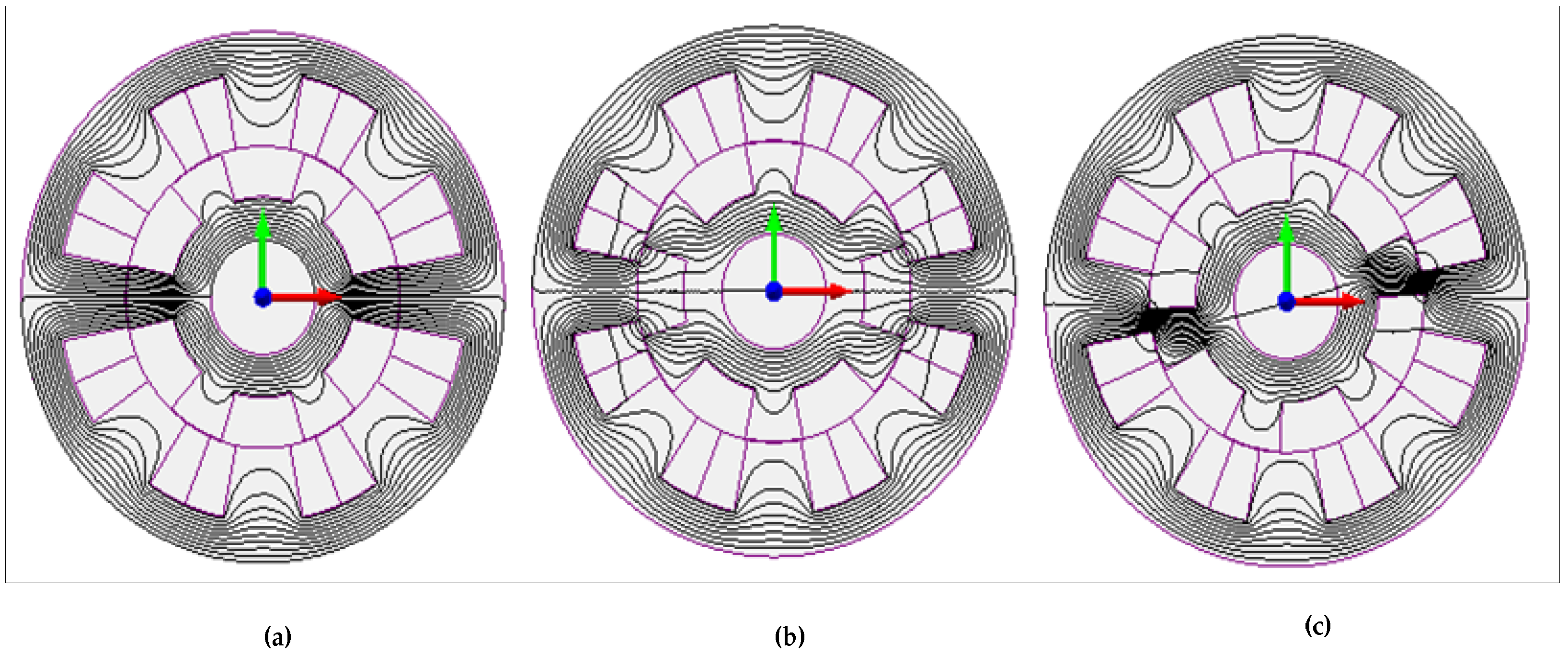
2.2. Modelling of Switched Reluctance Generator

The most important benefit of the SRG for a wind turbine is their ability to operate in a wide speed range. The SRG has simple structure. The rotor has no winding and both the rotor and stator have salient poles. The SRG inductance, torque, and flux linkage are totally dependent on the phase current and the position of rotor. In the generator operation mode, the phase excites in the negative slope of the inductance profile, as illustrated in Figure 5, where θon and θoff are the control parameters. The rotor moves from an aligned position (Figure 6a) to an unaligned position (Figure 6c). During this stage, the energy is delivered to the winding phase through a converter from the DC power source.
The voltage equation VDC-ph of each SRG phase is given by [26,27]:
V D C p h = L p h ( θ , i p h ) d i p h d t + R i p h + e p h
e p h = i p h ω L p h ( θ , i p h ) θ
where θ is the position of rotor, i is the phase current, Lj is the inductance, R is the phase resistance, and e represents the back-emf.
The instantaneous electromagnetic torque is given by [28,29,30,31]:
T j ( θ , i p h ) = d W ( θ , i p h ) d θ = 1 2 i p h 2 d L p h ( θ , i p h ) d θ
where W′ represents the coenergy. The total of electromagnetic torque T(θ, i) is determined from the sum of the electromagnetic torques of each phase Tj(θ, iph), as follows:
T ( θ , i ) = j = 1 n T j ( θ , i p h )
The basic formula for SRGs coupled with mechanical analysis is given by:
J d ω m d t = T m T S R G B ω m
ω m d t = θ
where Tm is the mechanical torque generated by the turbine (Nm), TSRG(=T(θ, i)) is the electromagnetic torque of the SRG (Nm), ωm is the mechanical speed (rad/sec), J is the moment of inertia (Kgm2), and B is the coefficient of viscous friction. The average power P of the SRG is defined as follows:
P = T ω m             = 1 2 i p h 2 d L p h ( θ , i p h ) d θ ω m
The operating principle of the SRG is based on the rotor position. To describe this reliance, it is sufficient to focus just on one phase. Each phase is controlled independently. The SRG structure has three particular positions [30].
Figure 6a shows the aligned position on the horizontal axis phase for a SRG 8/6. The magnetic circuit has a maximum inductance (Figure 5), maximum flux linkage, and minimum reluctance. The current in this position is not able to create torque because the magnetic reluctance has reached its minimum. In addition, the iron is sensitive to saturation, particularly in the rotor and stator yokes. For these reasons, the aligned inductance will be decreased.
The unaligned rotor position illustrated in Figure 6b for the same SRG is 8/6. At this position, due to the large air gap, the magnetic reluctance is at the maximum. The machine has a minimum inductance (Figure 5) and minimum flux linkage. The magnetic circuit is difficult to saturate. When the phase is excited, the unaligned position is unstable. In fact, in this position, there is no torque (Figure 5), but if the rotor is moved to either side, a torque is created which tends to move the rotor further into the next aligned position.
If the system is in an intermediate position (Figure 6c), in the presence of a current, the rotor moves to maximize its flux linkage, thus returning the machine to a stable position. The torque drive is required to allow movement to the non-aligned position. It is opposed to counter-clockwise rotation. Therefore, this area is relevant to the generator mode (Figure 5).

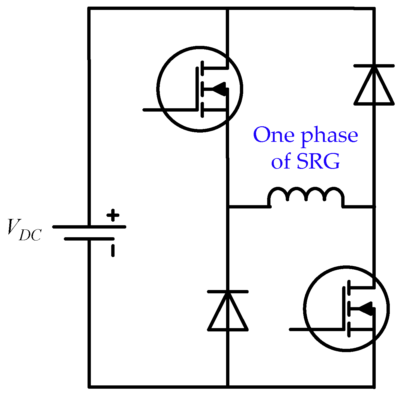
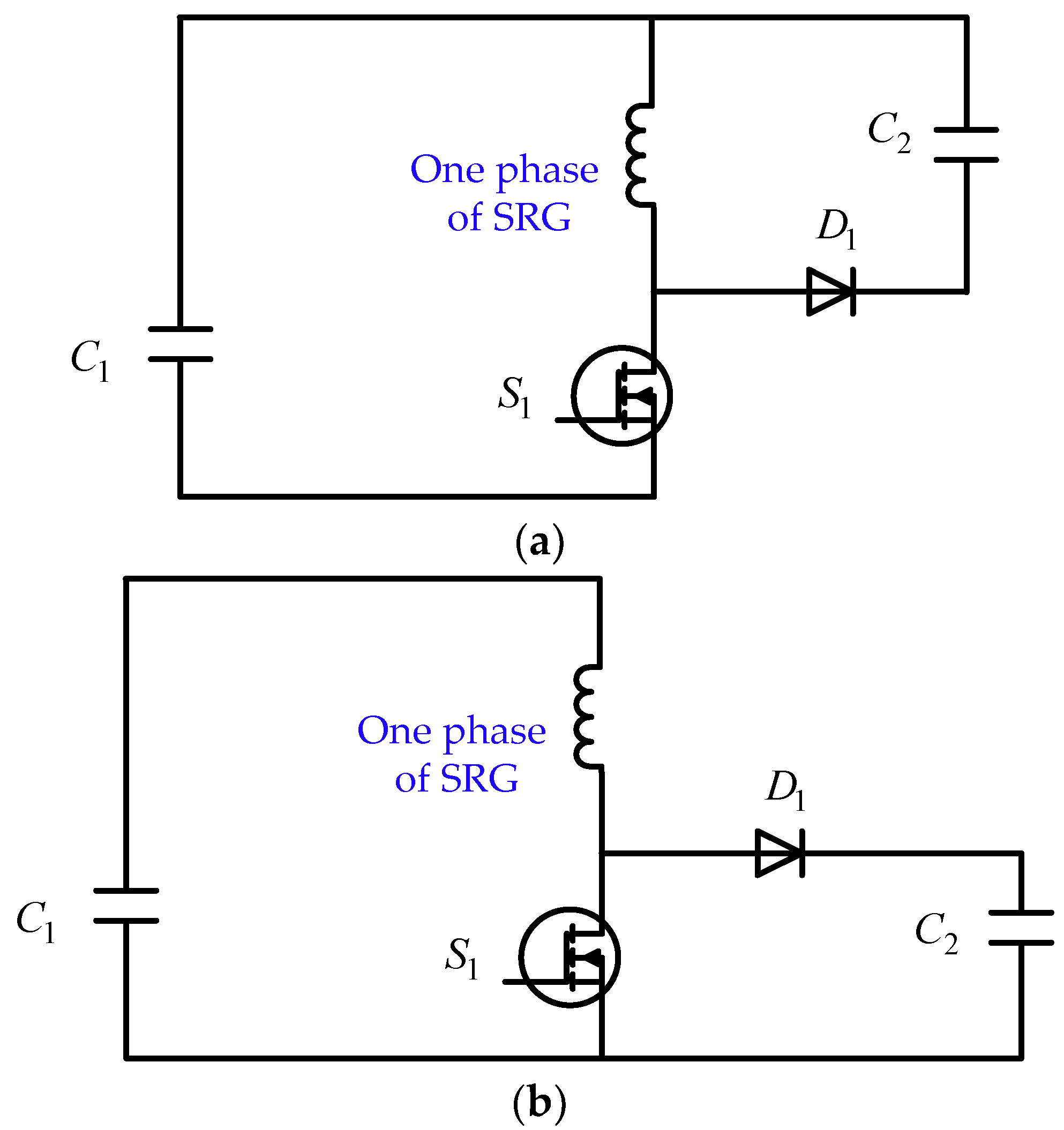
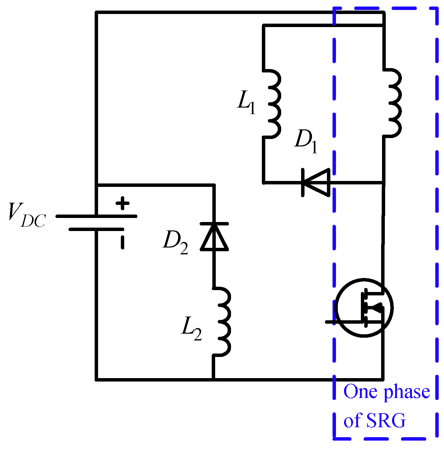
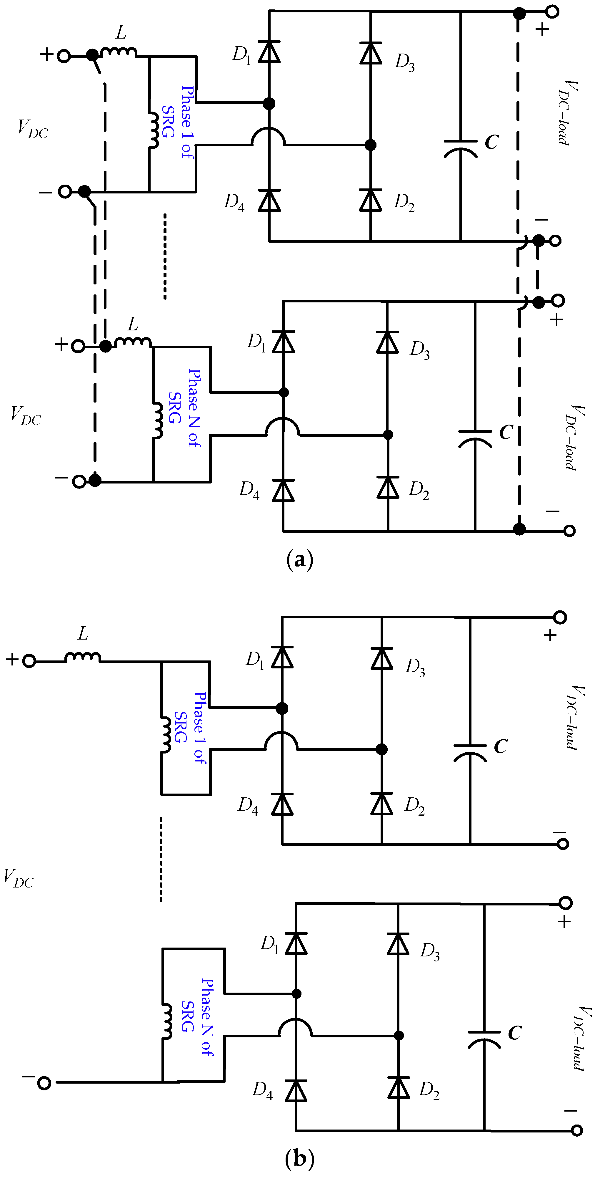
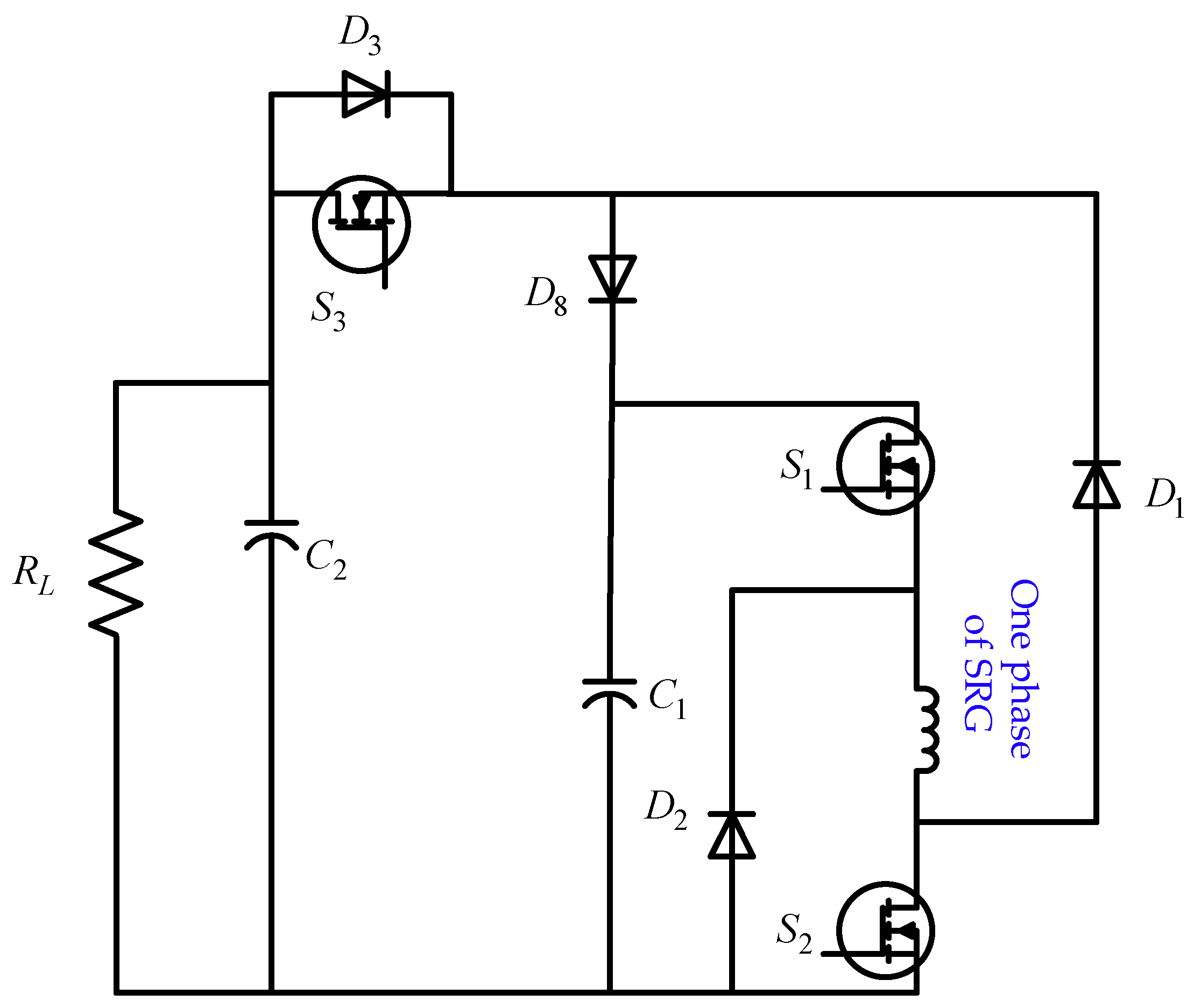
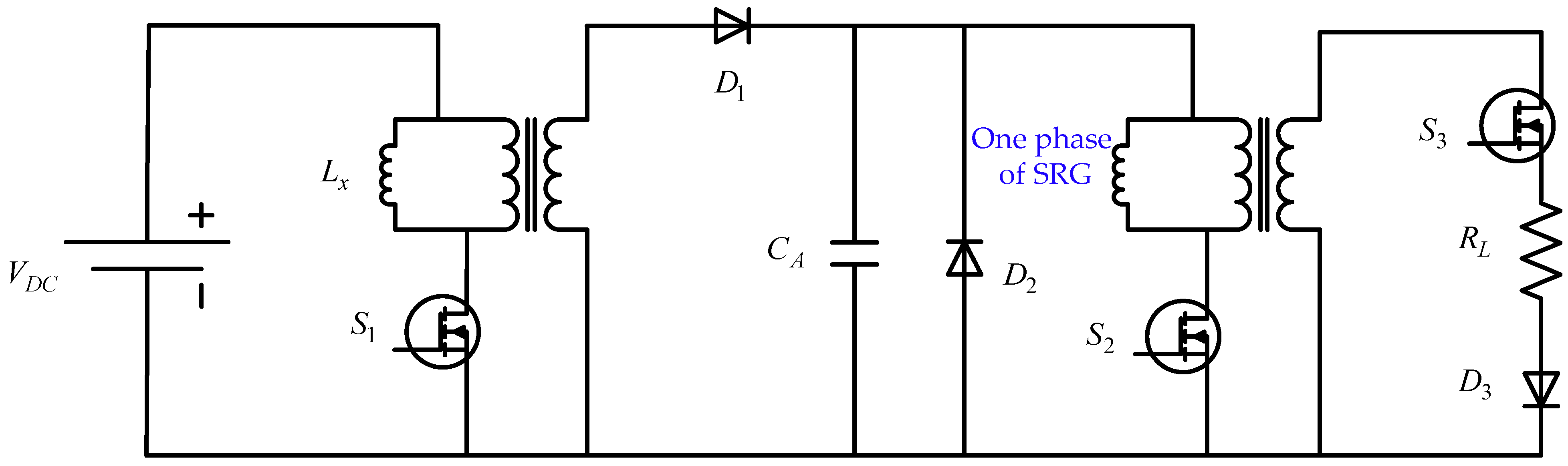
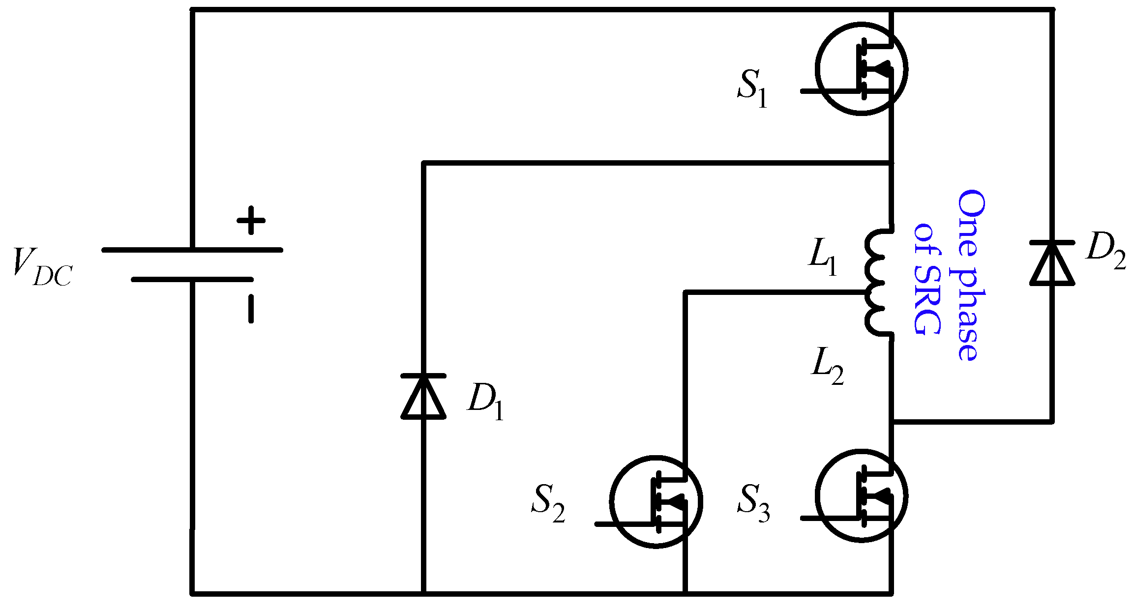
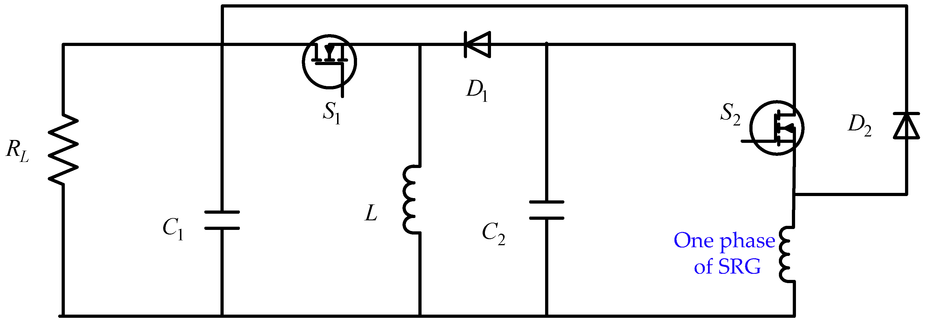
3. Converter Topologies of SRGs in WECS

The SRG power converter is related to both the performance and the cost of the system, since numerous research studies have been carried out on the topology of the SRG converter in the WECS to enhance the SRG performance. A general review of several types of power converters is presented in the literature [32]. The conventional SRG power converters in WECS are characterized mainly by providing two stages of voltage for the magnetization or generation of the machine winding. Among the SRG converter topologies in WECS, there is the traditional Asymmetric Half Bridge Converter (AHBC) topology, as shown in Figure 7 [33,34]. This uses 2n switches, where n is the SRG phase number. It is possible to operate in both hard and soft switching modes. In hard switching, there are two modes of operation: excitation and generation. In soft switching, there are three modes of operation: excitation, fly-wheeling, and generation [35]. This last commutation strategy is one of the most used, with applications in different fields, such as in WECS, the automotive industry, and aerospace, due to the high flexibility and the independence of phase control [36]. The main disadvantages are:
  • Lower demagnetization voltage at high rotational speed due to constant voltage power supply.
  • Necessity of a large capacitor on the power supply to filter the ripple of the voltage.
  • Conduction losses increase through the diodes in the generation mode due to the higher peak currents.
The boost and buck converters are shown in Figure 8. There are two modes of operation: excitation and generation. During the excitation mode, S1 is connected. The second state is when the switch S1 is turned off and the current is flowed from the diode D1 to the power supply. The advantages of these converter topologies are that just one switch per phase is required and each phase can be independently controlled. Their major drawback is that two separate voltage sources are required [30].
The feature of boost converters is the requirement for the output voltage to be higher than the input voltage, as shown in Figure 8a. In contrast, the output voltage of buck converters is less than the input voltage [30], as shown in Figure 8b. The lower voltage output causes a longer output period with slower flux extinction.
Figure 9 represents a Derishzadeh converter topology for SRGs in WECS [37]. It needs only a switch, two inductors and two diodes for each phase of the machine [38]. When the switch S is activated, the magnetization phase begins. During this period, the energy flows from the source VDC to the phase winding, since the current increases in the phase winding. When the switch is deactivated, the generation phase has started. As a result, the phase winding current flows in the primary inductor (L1), thus D2 conducts. Then the current starts to flow in the coupled secondary inductor (L2). Meanwhile, the demagnetization energy is being returned to the VDC. The diode D2 is turned off, when the phase current and the current in the magnetizing inductor are equal, and the current in the secondary inductor becomes zero. Their major drawback is the complexity of control.
The advantages of this converter are summarized as follows:
  • Only one switch is used per phase with separate phase control.
  • Fast demagnetization capability with one switch in each phase.
  • Only one power supply is required for gate drive circuits.
Figure 10 shows Vujicic–Calasan SRG power converter topologies. There are two types of Vujicic–Calasan converter, PCT 1 and PCT 2. These converter topologies are not using any controlled switches such as the traditional converter or the Deriszhadeh converter topologies [37,39]. Since it does not require the information from the position sensor, it simplifies the SRG control. In fact, the SRG output power can be controlled easily by adjusting the DC voltage. Figure 10a shows the PTC1 circuit, a separate inductance filter is used on each winding phase and an independent voltage supply can be applied on each phase to separately control their individual powers.
However, Figure 10b shows the PTC2 circuit, which utilizes a separate inductance filter for each phase winding. To control the SRG power, only one VDC voltage source is used as excitation. The diode bridge assures the flow of current to the load Vdc-load, but guarantees at the same time that the phase voltage Vph doesn’t exceed the ±Vdc-load value. During the periods of magnetization, the phase current can be less than the idc current, thus expanding the current loop. The two proposed converter topologies are both suitable for low-cost applications as they do not contain controlled switches. They contain only inductance filters and diodes. Furthermore, the output power of the SRG can be controlled simply by varying the DC excitation voltage without the need for a hysteresis current controller. Preferably, the SRG operation should be close to the highest speed in order to minimize the need for inductance filters and to maximize the available power.
Figure 11 illustrates an active boost power converter for the SRG. It is composed of the integration of an AHBC and a front-end circuit [40]. The front end is composed by a diode, a switch, and two capacitors which are used in combination to achieve the different modes of operation. When the S3 is switched off, the boost capacitor C1 is charged by D8. In contrast, if S3 is switched on, the system supplies energy to the output of capacitor C2. The active boost power converter is robust and efficient compared to conventional topologies. It is more suitable for operations above applications with a wide speed range, such as distributed wind energy systems or other generations that are connected to the DC bus.
Figure 12 shows an accumulator capacitor converter (ACC). This converter has four modes of operation for improved SRG performance, which are initial charging, magnetization, freewheeling and generation [41,42]. At high speeds, it allows the SRG to generate a considerable quantity of energy. This topology of converter is designed with a no-load flyback and the coil is forced magnetically. Additionally, the filter circuit consists of a capacitor and inductor. It can produce considerable energy at high speeds, and the energy fed back to the power supply is reduced. The energy of magnetization is collected in a storage capacitor. It is determined using no-load flyback operation. The energy is then discharged through the capacitor into the coils forcibly.
A Dong converter topology of SRG is shown in Figure 13. Compared to the traditional topology, it provides a higher excitation current in order to guarantee the efficiency of the generation capacity at low speed [43].
Figure 14 shows a SRG converter using a variable DC link (VDC). The main operation is explained in this figure. During the excitation mode, S1 is switched on and the current flows to the SRG phase winding, S1 and C2. After the commutation of S1, the current circulates in the phase winding of the SRG and D2. It also charges the capacitor C1.
The main advantage of the CvDC is the higher voltage excitation capability. It is a good candidate for SRGs with higher speed. Furthermore, the lower apparent power of the pulse converter compared to the converter with discharge capacitor [44]. The main disadvantage of the CvDC is the higher losses on the pulse converter components.
Furthermore, the previous converter topologies are compared in terms of diode numbers, switch numbers, control complexity, fault tolerance and the utilization of the sensor position. The above comparisons are outlined in Table 2. A large number of switch elements are required for the active power converter, the dong converter and the variable DC link converter (CvDC). Thus, the loss in switching is higher compared to the losses of the switching of the converter of Derishzadeh. The converters PCT1 and PCT2 require the highest number of diodes and therefore have the largest diode losses compared to diode losses in AHBC and Derishzadeh converters. Moreover, the Vujicic-Calasan converters have no switching elements and thus do not need any control logic or information from position sensors. Therefore, they are a cheaper and more efficient solution than other power converters.

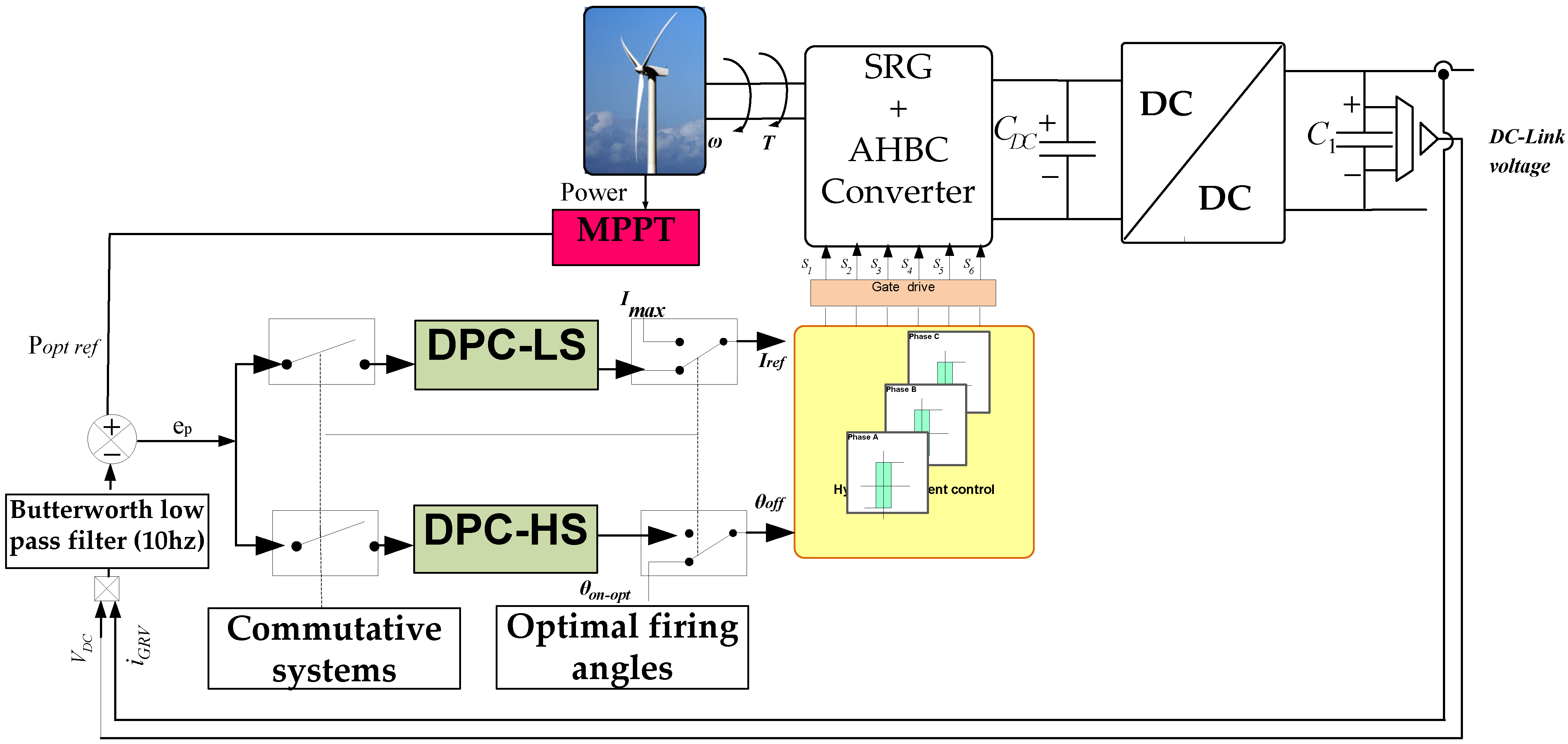
4. Advanced Control Techniques Overview

The torque ripple and the acoustic noise are inherent drawbacks of SRGs [46]. They are mainly caused by radial vibrations [47]. Furthermore, the voltage ripple is the major limitation of the SRG in the WECS. It reduces the life of the load or the battery. Therefore, an improvement of the SRG system is urgently needed to solve the problems of torque and voltage ripple. To offer clear and simple solutions to the problems of SRGs, the present section aims to review the state-of-the-art developments to reduce these problems, mainly through control strategy design. Moreover, these SRG control methods will be described and compared in terms of their benefits and limitations.

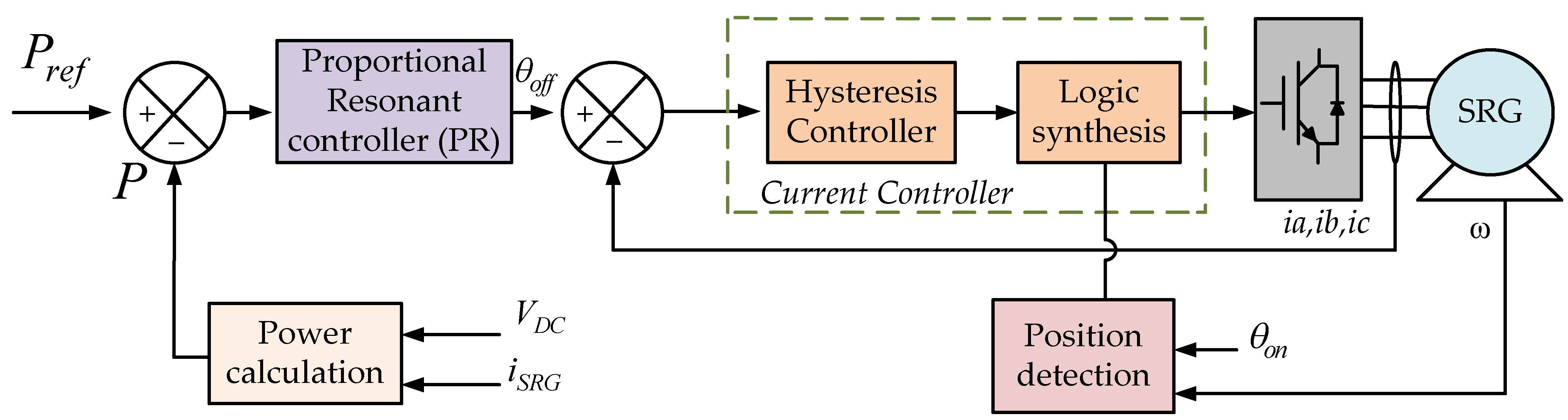
4.1. Control Strategy

4.1.1. Power Control Strategies

Due to the operating principle of SR machines, the gradients of inductance in the area of the minimum and maximum inductance are both extremely small, which causes a drop in torque of the phase switching region, leading to torque and voltage ripple [48]. Direct Power Control (DPC) techniques are proposed in [49,50]. DPC has been employed and designed to allow the performance of the SRG over a wide range of speed variations, as shown in Figure 15. Two forms of DPC have been applied: DPC by hysteresis during low speed operation, and DPC by a single current pulse during high speed operation. To enhance the SRG performance, the DPC was tested with Proportional-Integral (PI) controllers and Sliding Mode (SM) controllers. A detailed discussion of the SM control principle used can be seen in [51,52]. The basic concept of the control method is to control the state from its original condition to the desired state through a switching surface. Based on the experimental results, the authors confirm that the SM controller achieved better performance than the PI controller. The Proportional Resonant (PR) regulator can also provide better performance than the PI controller in WECS, as presented in [53].
In [54], a proportional resonant controller is proposed, which is applied for direct power control of the SRG. Figure 16 illustrates the block diagram of the scheme. The PR controller handles the error between the measured power (P) and the reference (Pref).
The proposed scheme allows the control of the power injected into the DC link using the turn-off angle. The authors demonstrate that the PR controller decreases the power ripple compared to the PI controller. A method of Modified Angular Position Control (MAPC) is described in [55]. The MAPC method has several advantages such as high dynamic response over a wide range of speeds and simplicity of implementation. In addition, the torque setting range is large. It is also possible to conduct several phases at the same time.
In [56], the authors presented a simple, innovative and more efficient control strategy for SRGs, which operate in continuous conduction mode (CCM) for WECS. They described a method for the determination of optimal control parameters, which provides the maximum SRG output power. The advantages of CCM are very effective, robust, and ensure good tracking of the maximum output power point when the characteristics of the SRG change.

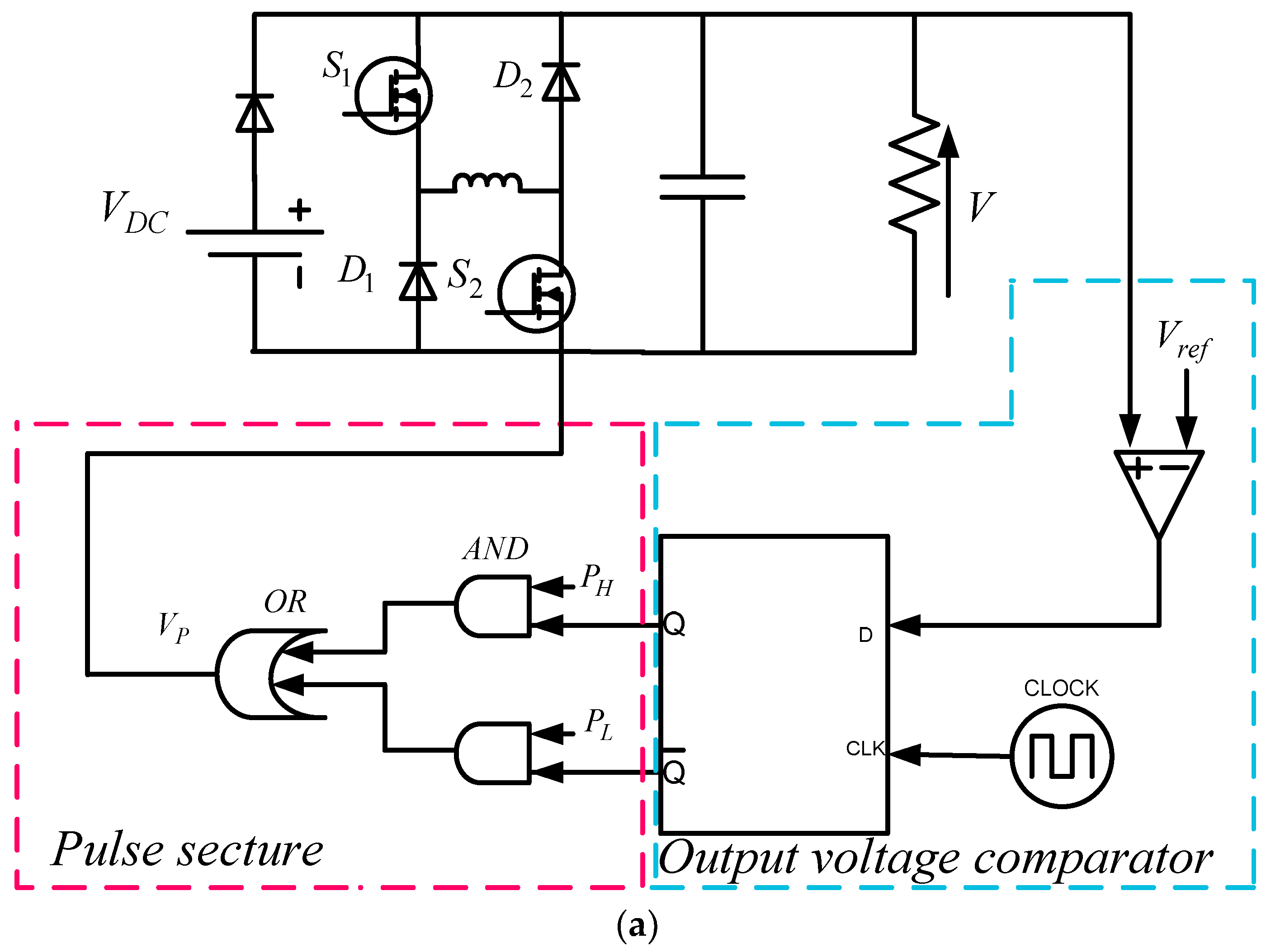
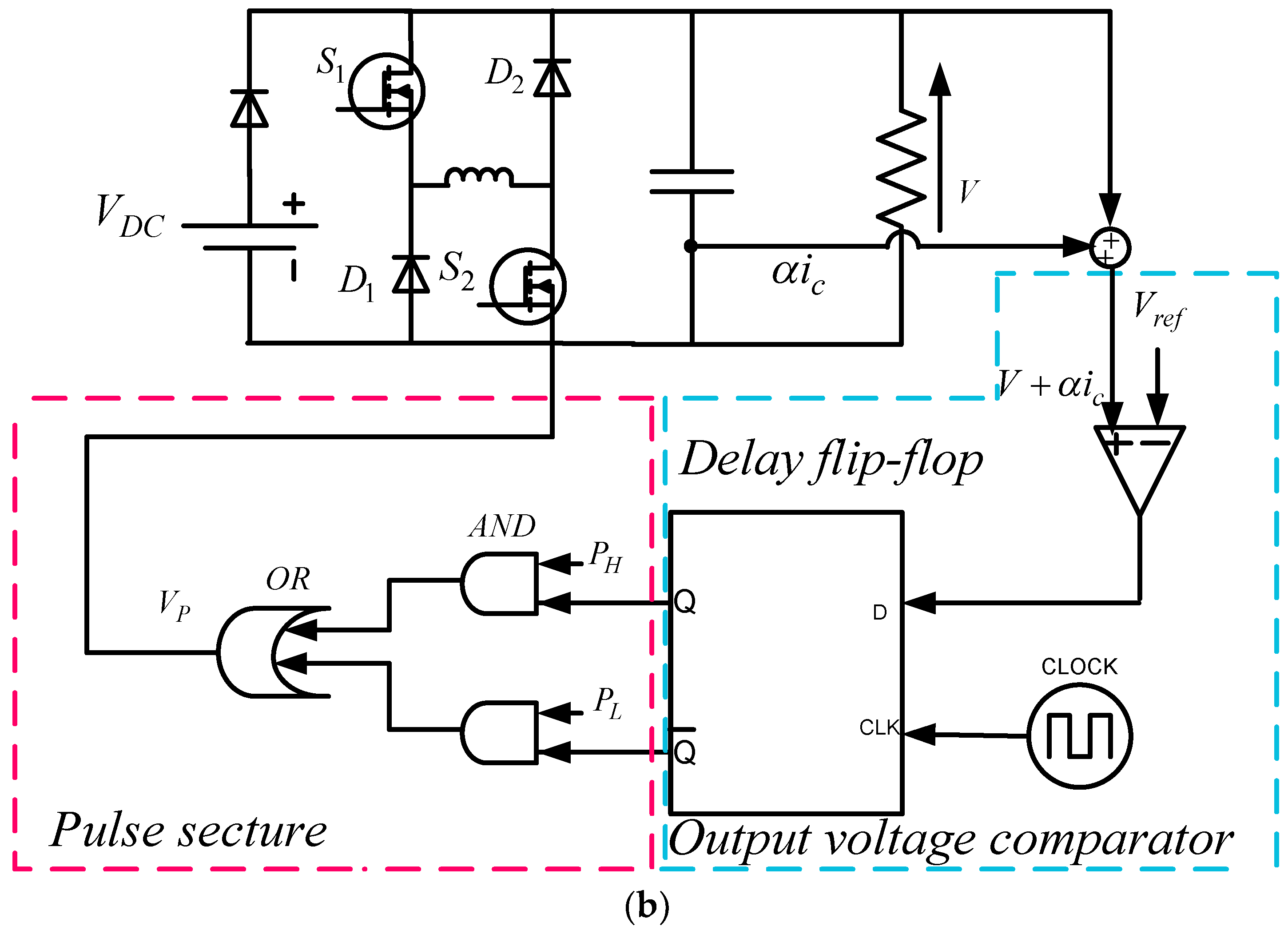
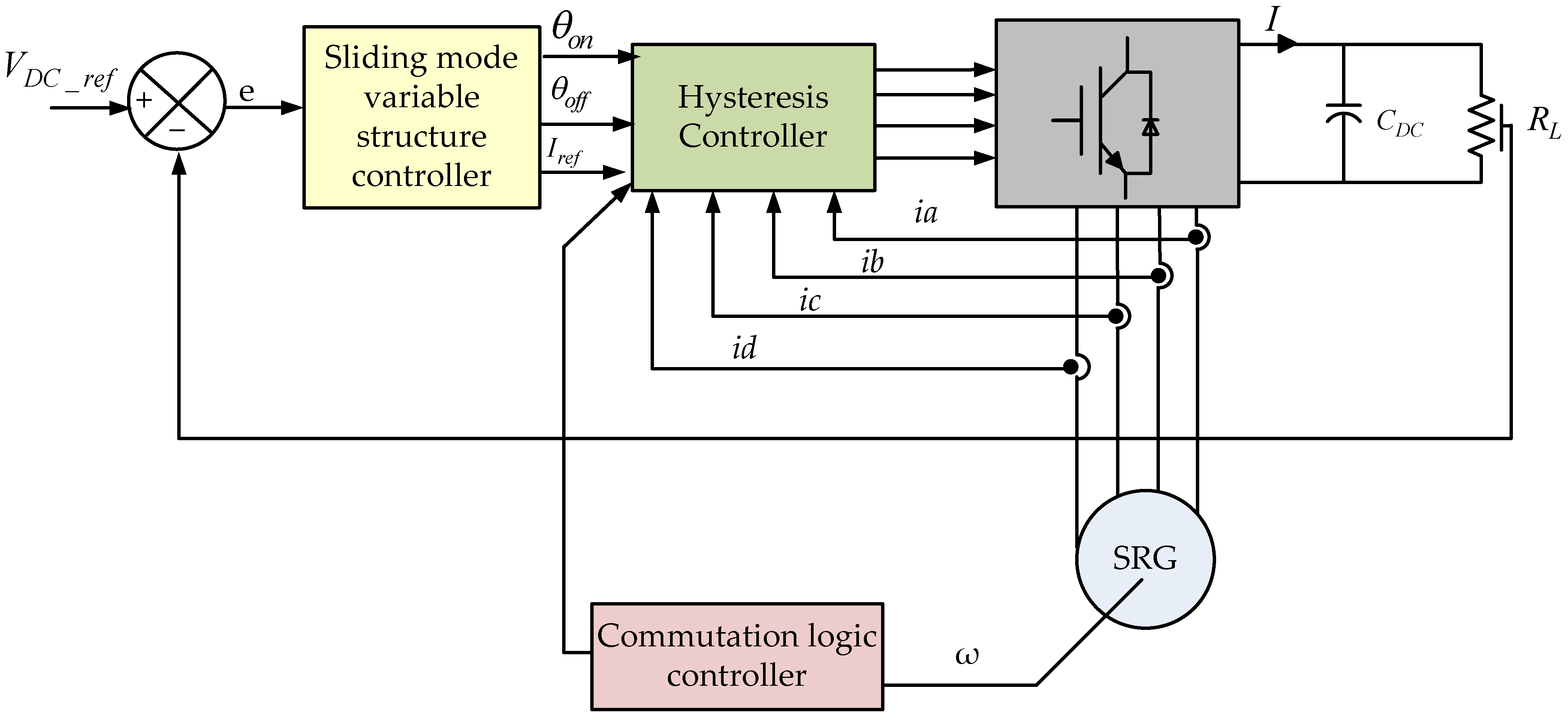
4.1.2. Voltage Control Strategies

The SRG system under PI controller is proposed in [33,57]. This approach provides a fast start-up response and provides the stability of the system. Consequently, this method of PI control has a good ability to respond to varying wind speeds and loading conditions, which makes the system even more attractive for wind generation systems. A control of SRGs for low voltage Dc micro-grid was presented in [35]. The analysis of the energy conversion to achieve the maximum drive performance is presented taking into consideration the electrical machine, power converter losses, and the external excitation source. The control of DC bus voltage based on PI regulator despite load variations or any external disturbance are highlighted.
The traditional Proportional-Integral-Derivative (PID) controller has been combined with a tracking technique, as proposed in [58], to improve the efficiency of the SRG output voltage. The SRG was controlled at different output voltage set points and the efficiency and torque ripple performance of the machine were evaluated. The classical PID control system has a number of advantages, including its relative simplicity of design, its simple structure and its low cost. However, this controller has some limitations, such as poor performance when its parameters are not correctly adjusted, especially when the control object is non-linear.
The Fly-Wheeling Pulse Train (FW-PT) drive system is suggested in [59]. In order to eliminate the voltage ripple, the impact of the control parameters on voltage ripple is analyzed. Compared to conventional control, the FW-PT control system regulates the output voltage by two or more combinations of predefined control pulses. The block diagram of the FW-PT drive is shown in Figure 17a. The FW-PT control chooses the high and low duty cycle pulse trains based on a comparison between the output voltage V and the reference value Vref. Therefore, their advantages are the simplicity of the circuit implementation, the fast response time, and the absence of network compensation.
A SRG system based on the conventional control with Pulse Width Modulation (PWM), and Current Chopping Control (CCC) has a limitation of low speed response [60]. To provide a fast response, the Capacitor Current Pulse Train (CC-PT) control was modified and adopted to regulate the output voltage of the SRG system, as present in [61]. Figure 17b shows the CC-PT control of a one phase of a SRG. Compared to conventional control, the CC-PT control offers the following main advantages:
  • The CC-PT control approach can regulate the output voltage using two or more predefined control pulse combinations. This method has advantages in terms of simplicity of circuit structure and the elimination of a compensation network.
  • The method of CC-PT control can achieve a fast start-up response without overshoot
  • The current in the start-up is reduced, which makes the system more reliable and economical. The output voltage ripple is lower than 5% of the nominal value.
In [62,63], a pulse control approach applied to a flyback converter which operates in Discontinuous Conduction Mode (DCM) was introduced. This technique has many advantages over conventional control, such as fast transient response, simplicity of design and implementation, and accuracy. As proposed in [64], a Sliding Mode Control (SMC) approach has been applied to the output voltage control of the SRG. Based on the error of tracking, the SMC controller fixes the reference to a hysteresis controller, in order to set the phase currents around their reference, as shown in Figure 18. In [65], the authors show that when compared to the conventional PID controller, the SMC controller can achieve significant enhancement in the dynamic characteristics of the switching process.
A new modulation-demodulation strategy to achieve efficient Power Line Communication (PLC) between SRGs and other converters is presented in [66]. The author’s objectives are to maximize the SRG performance with stable and reliable communication of the system. The modulation method regulates the SRG angular commutation to modulate the voltage ripples.
As proposed in [67], the SRG flux linkage model is developed based on a Fuzzy Inference System (FIS). The FIS has been developed using different membership functions such as trapezoidal, triangular, Gbell, psigmoid, and Gaussian. The triangular membership function developed in FIS has the following advantages: fast computation speed, simple structure and robustness characteristics. It performs well when applied to modelling, prediction and control. As proposed in [68], a simplified current rise model allows the estimation of the steady-state of SRG peak current for different operation conditions such as DC-link voltage, speed, and turn-off current level. The drawbacks of this suggested model are the following: The model circuit is applied just to a particular interval and when the interval changes, the parameters of the model must be recalculated. In [69], the authors proposed a Model Predictive Control (MPC) for SRGs driven in wind power generation system. The MPC approach is applied to the phase winding through a z-source converter to generate the desired voltage.

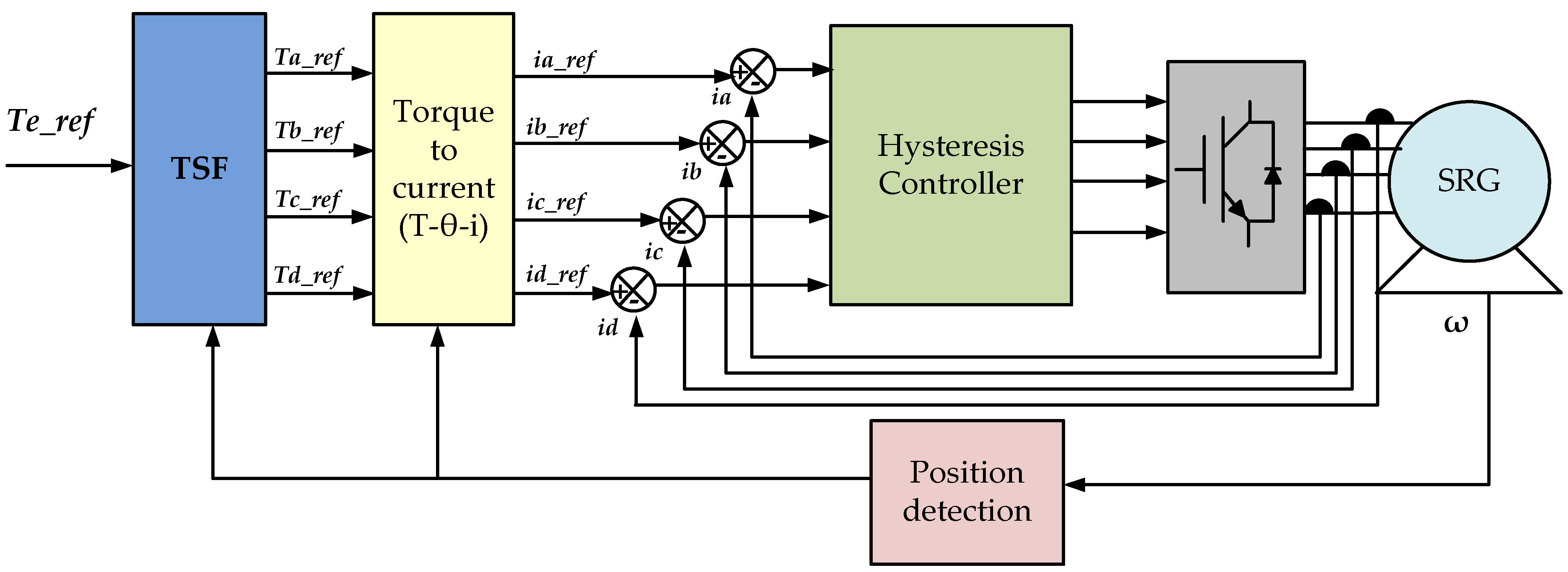
4.1.3. Torque Control Strategies

The switched reluctance machines have been mainly applied to drive motors, and numerous studies on torque ripple reduction in the motor mode have been conducted extensively [48,70]. Among the most practical control strategies is the Torque Sharing Function (TSF) method. To reduce the ripple of SRM torque, the TSF approach controls the torque output of individual phases to divide the torque reference between all phases, while maintaining the total of phase’s torque references equal to the desired torque. The TFSs can be classified on the basis of the functions used in their implementation. For example, some widely used TSFs functions based on sinusoidal [71], linear [72] and exponential [73].
Though the above mentioned TSF functions are mainly developed for motor mode operation, they can also be used in generator mode (SRG). However, the efficiency of the SRG can be significantly enhanced. In contrast to motor mode, each phase of the SRG begins to flow current when its phase inductance is close to its maximum value. This high inductance ensures that the current does not build up quickly to the desired value. As presented in [74], a non-unitary TSF control strategies for SRGs in WECS. Figure 19 presents the TSF-based torque control scheme for a four-phase SRG. The authors demonstrated the minimization of torque ripple in a wide range of operating speeds.
The comparisons of the different control methods mentioned are presented in Table 3.

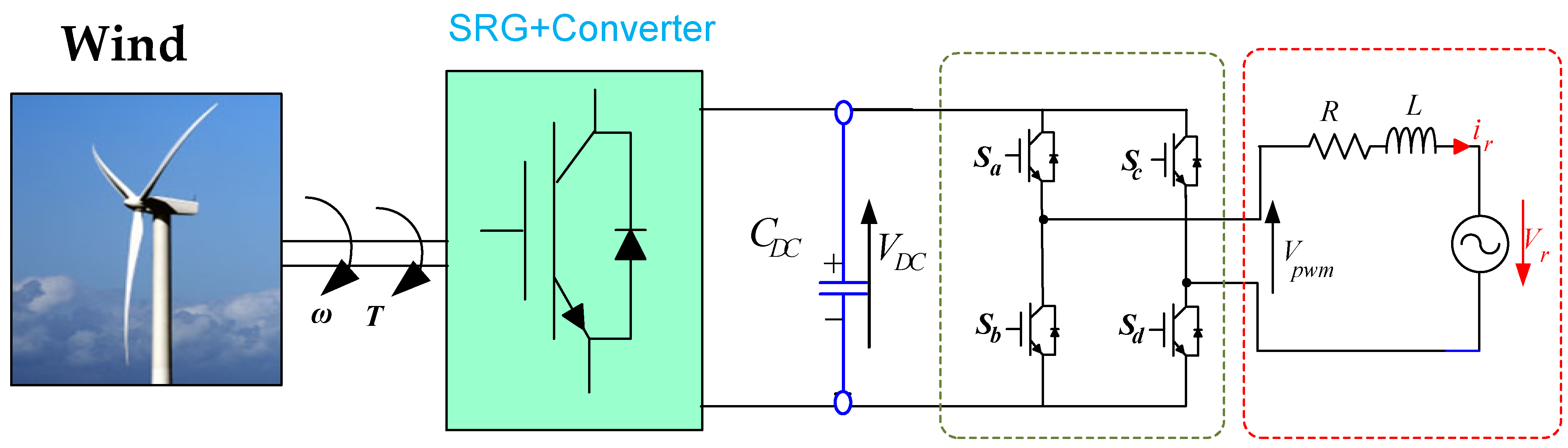
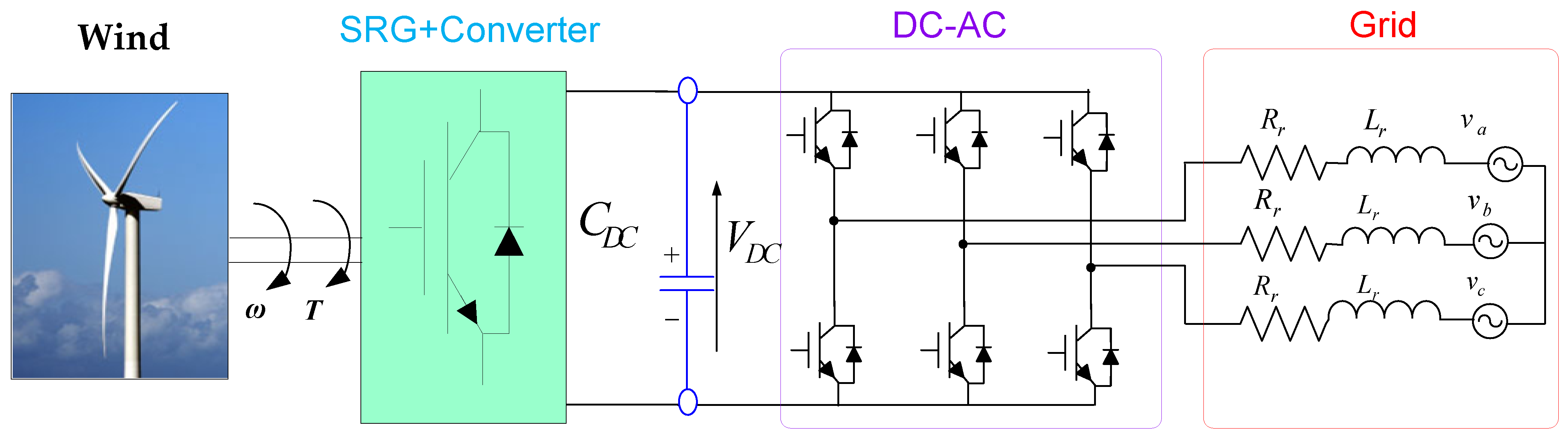
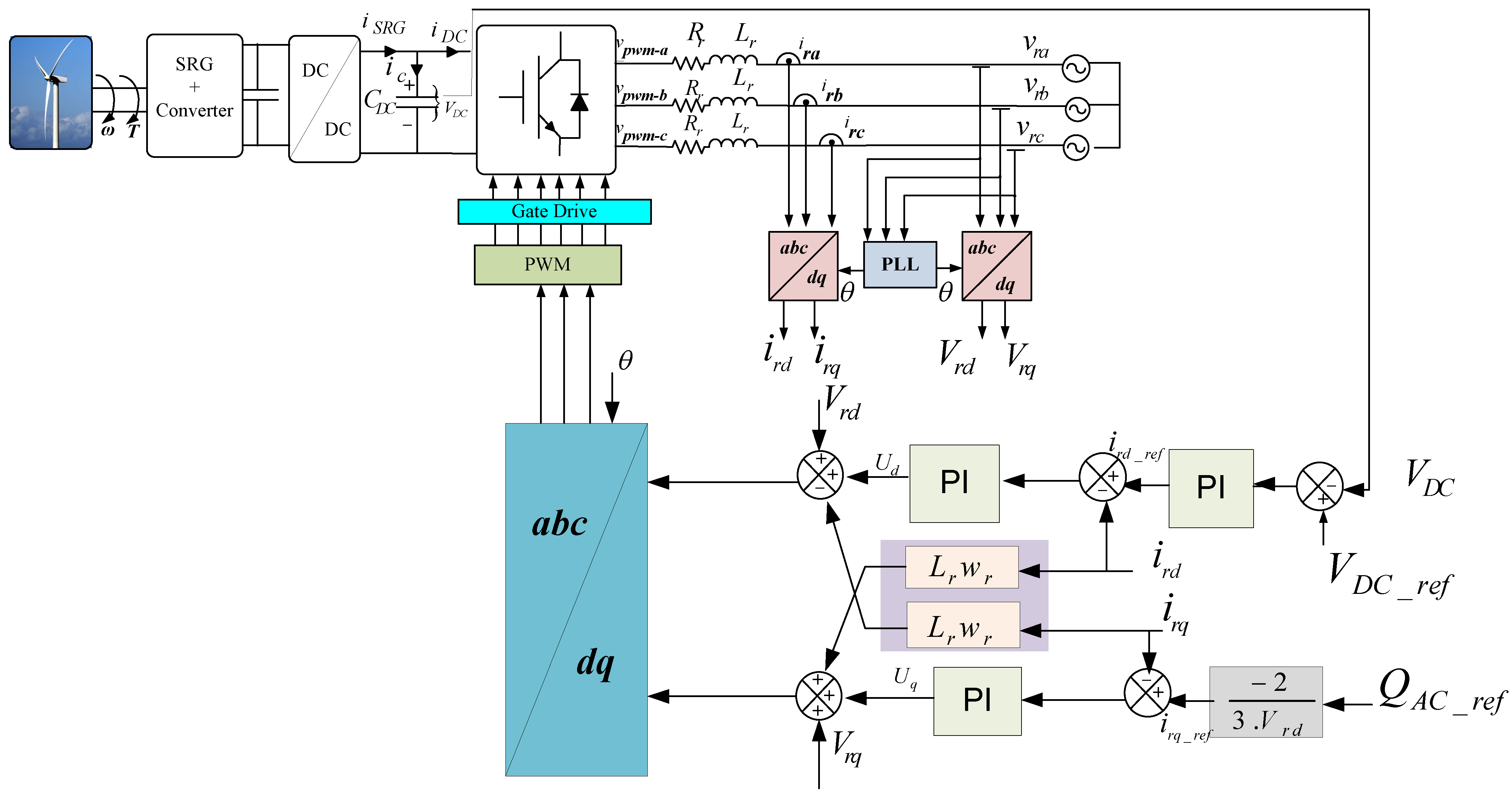
4.2. Control Strategy of SRG Connected to the Grid

In this section, we focus on the SRG connected to the grid for a WECS application. In our literature review, we found few experimental studies on the connection of SRGs to a power grid. In [75,76,77], a single-phase inverter was used to connect the SRG with the grid. As shown in Figure 20, the block diagram of a SRG is connected to a DC-AC converter, which maintains the DC bus voltage through a PI regulator. A resonant corrector is used to follow the sinusoidal current setpoint, as proposed in [78]. The inverter must meet a number of standards: the quality of the power supplied to the grid, the nominal voltage and frequency of the grid, and the maintenance of DC-bus voltage. The SRG controller must ensure maximum extraction of the mechanical power available and guarantee maximum conversion efficiency.
As mentioned in [76], a suggestion for the connection of a SRG to the electrical grid. The objective of the work was to provide a strategy for supplying active power to the electrical system by regulating the injected current. The generated SRG voltage was based on the firing angle variation. A resonant compensator with current control was used. Some articles deal with the connection of a SRG to the electrical grid in variable speed wind power systems. The bloc diagram of a SRG connected to grid is present in Figure 21.
A bidirectional DC-DC converter is applied as an interface between the SRG converter and the grid VSC in the wind power system. Different literature review studies [49,79,80,81,82] have shown that the bidirectional converter operates to maintain the SRG excitation voltage, while the Voltage Source Converter (VSC) maintains the DC-bus voltage regulated. Figure 22 shows the VSC control. It regulates the VDC voltage and generates the flow of energy from the SRG to the grid.
The phase-locked loop (PLL) techniques have been used to ensure the synchronization between grid-interfaced converters and the utility network [83]. In [84], a speed-control system based on adaptive neural network current control has presented. The SRG has been connected to a power grid through the VSC control. To enhance the quality of SRG power, in-loop filtering approaches are presented in [85]. These methods are based on the elimination of voltage ripples in the DC link voltage due to the SRG switching operation. In [86], the authors address a DC micro-grid, they use an DC-DC interleaved converter to raise the output of the SRG voltage from 48 V to 400 V.
A robust and slave control scheme is designed to generate sinusoidal output voltage waveforms under non-linear and unbalanced loads. An analysis of a wireless control system for SRG based WECS is proposed in [87,88], when a General Packet Radio Service (GPRS)/Enhanced GPRS (EGPRS) data service is employed. The wireless power control system is presented in Figure 23. The effectiveness of the system is studied by co-simulation, including the dynamics of the wind generator and the effects of the wireless channel.
A small-scale wind based on SRGs in regions where the grid was weak or even not covered was suggested in [89]. Figure 24 shows the generation unit process wind energy into electrical power. Therefore, a power tracking control and a power balance control have been developed. The proposed power balance controller combines three main systems: the power generation system, the load, and the energy storage unit. As proposed in [90], a microgrid (MG) based on a SRG with power support plug-in. A reconfigured boost converter provides the voltage of the MG. The SRG and the common DC bus voltage of the MG are regulated and experimentally validated.

5. Multi-Objective Optimization of SRG in WECS

The power output profiles of the SRG are also influenced by a number of factors such as load current, phase voltage, phase inductance, speed, and rotor position. Many researchers have carried out extensive research into the optimization of control parameters [91,92,93,94,95,96,97,98]. Therefore, the challenge for researchers is to design an optimal control of the output power of a SRG that takes into account all influencing factors.
The literature [99] have proposed a control method to maximize the extraction of wind power and the efficiency of a SRG by adjusting the turn on angle and the turn off angle using a PSO algorithm. A method of optimization based on a fuzzy algorithm and parameter scanning is proposed in [100]. The objective of authors is to enhance the performance at low speeds of high efficiency generators. The optimization objectives are the maximum power output, the system efficiency and the smoothing torque coefficient of the SRG. The experimental results show that this method can improve the output power to 642.53 W and the system efficiency to 69.43%. Due to the substantial non-linearity of SRGs, a strategy control method to estimate the optimal PI controller values of the SRG voltage control using the grasshopper optimization algorithm has been presented in [101].
As presented in [102], two optimization techniques such as Particle Swarm Optimization (PSO) and Gravitational Search Algorithm (GSA) have been used to obtain appropriate combinations of activation and deactivation angles for the AHBC. The generator performance has been analyzed in terms of its output voltage, power, current, and speed at various wind speed conditions. The authors concluded that PSO performs better than GSA in terms of efficiency, computation time, and torque ripple. A strategy proposed in [103] to improve efficiency based on optimal angles of turn-on and turn-off. The authors have eliminated the position sensor and improved the reliability of the SRG system.

6. Conclusions and Outlook

This paper presents a comprehensive review on the design of SRGs in WECS, including the aspects of the mathematical modeling of the turbine and SRG. In the context of WECS, this article has reviewed the power converter structures and dedicated controllers for SRGs and aims to contribute to the technical discussion by exposing the state of the art, and help to formulate open research questions, which can in future contribute to the development of SRGs in the wind generator industry. As presented in Section 3, several topologies of power converters were proposed in the last years, however, it is still not widely agreed which of them could be chosen to promote their use by the wind power generators industry. In order to comply with all the requirements of SRG-based WECS, such as high-dynamic performance, efficient operation and compliance with grid codes, the control system of SRG-based WECS must be separated into the control of the generator-side converter and the control of the grid-side converter. In this way, the advances made in control systems dedicated to the power electronic interfaces to power grid can be harnessed to foster the use of the SRG. However, the need to integrate multiple generators and the need to respect grid codes are challenges that drive research opportunities. However, many technical challenges still remain for SR machines in wind power application, such as ripple of voltage, ripple of torque, modelling and manufacturing difficulties, and sensorless control under abnormal conditions. Meanwhile, new SRM and drive technologies will play a significant role in making wind energy systems more cost-effective, reliable and efficient.
This paper provides researchers and engineers who are interested in switched reluctance machines and drives for wind power generation systems with a comprehensive reference and blueprint. Looking at the state-of-the-art can be helpful and may well trigger a generation of other innovative ideas in this fast-growing field.

Author Contributions

Conceptualization, Z.T., R.E.A. and A.K.; methodology, R.E.A. and A.K.; validation, Z.T., M.P., R.E.A. and A.K.; formal analysis, Z.T., R.E.A. and A.K.; investigation, Z.T., M.P., R.E.A. and A.K.; resources, Z.T., A.K. and R.E.A.; data curation, Z.T.; writing—original draft preparation, Z.T. and R.E.A.; writing—review and editing, Z.T., M.P., R.E.A. and A.K.; supervision, R.E.A. All authors have read and agreed to the published version of the manuscript.

Funding

This study was financed in part by the University of Sousse, in part the participation of Manuel Pereira by National Funds through the Portuguese funding agency, FCT—Fundação para a Ciência e a Tecnologia, under Scholarship SFRH/BD/04583/2020. The participation of Rui Esteves Araújo in this work was financed by National Funds through the Portuguese funding agency, FCT—Fundação para a Ciência e a Tecnologia, within project UIDB/50014/2020.

Institutional Review Board Statement

Not applicable.

Informed Consent Statement

Not applicable.

Data Availability Statement

Not applicable.

Conflicts of Interest

The authors declare no conflict of interest.

References

  1. Chen, H.; Zuo, Y.; Chau, K.T.; Zhao, W.; Lee, C.H. Modern electric machines and drives for wind power generation: A review of opportunities and challenges. IET Renew. Power Gener. 2021, 15, 1864–1887. [Google Scholar] [CrossRef]
  2. Cheng, M.; Zhu, Y. The state of the art of wind energy conversion systems and technologies: A review. Energy Convers. Manag. 2014, 88, 332–347. [Google Scholar] [CrossRef]
  3. Tsai, C.W.; Lin, C.L.; Huang, C.H. Microbrushless DC motor control design based on real-coded structural genetic algorithm. IEEE/ASME Trans. Mechatron. 2010, 16, 151–159. [Google Scholar] [CrossRef]
  4. Zhang, Z.; Yan, Y.; Tao, Y. A new topology of low speed doubly salient brushless DC generator for wind power generation. IEEE Trans. Magn. 2011, 48, 1227–1233. [Google Scholar] [CrossRef]
  5. Sethuraman, L.; Dykes, K.L. GeneratorSE: A Sizing Tool for Variable-Speed Wind Turbine Generators (No. NREL/TP-5000-66462); National Renewable Energy Lab (NREL): Golden, CO, USA, 2017. [Google Scholar] [CrossRef]
  6. Han, P.; Cheng, M.; Ademi, S.; Jovanovic, M.G. Brushless doubly-fed machines: Opportunities and challenges. Chin. J. Electr. Eng. 2018, 4, 1–17. [Google Scholar] [CrossRef]
  7. Strous, T.D.; Polinder, H.; Ferreira, J.A. Brushless doubly-fed induction machines for wind turbines: Developments and research challenges. IET Electr. Power Appl. 2017, 11, 991–1000. [Google Scholar] [CrossRef]
  8. Muller, S.; Deicke, M.; De Doncker, R.W. Doubly fed induction generator systems for wind turbines. IEEE Ind. Appl. Mag. 2002, 8, 26–33. [Google Scholar] [CrossRef]
  9. Ademi, S.; Jovanović, M.G.; Hasan, M. Control of brushless doubly-fed reluctance generators for wind energy conversion systems. IEEE Trans. Energy Convers. 2015, 30, 596–604. [Google Scholar] [CrossRef]
  10. Gupta, A.; Jain, D.K.; Dahiya, S. Some investigations on recent advances in wind energy conversion systems. In Proceedings of the 2012 IACSIT Coimbatore Conferences, IPCSIT, Coimbatore, India, 18–19 February 2012; pp. 47–52. [Google Scholar]
  11. Jain, A.; Shankar, S.; Vanitha, V.J.J.O.G.E. Power generation using permanent magnet synchronous generator (PMSG) based variable speed wind energy conversion system (WECS): An overview. J. Green Eng. 2017, 7, 477–504. [Google Scholar] [CrossRef] [Green Version]
  12. Yaramasu, V.; Wu, B.; Sen, P.C.; Kouro, S.; Narimani, M. High-power wind energy conversion systems: State-of-the-art and emerging technologies. Proc. IEEE 2015, 103, 740–788. [Google Scholar] [CrossRef]
  13. Chatterjee, S.; Chatterjee, S. Review on the techno-commercial aspects of wind energy conversion system. IET Renew. Power Gener. 2018, 12, 1581–1608. [Google Scholar] [CrossRef]
  14. Okundamiya, M.S. Power electronics for grid integration of wind power generation system. J. Commun. Technol. Electron. 2016, 9, 10–16. [Google Scholar] [CrossRef]
  15. Lebsir, A.; Bentounsi, A.; Benbouzid, M.; Mangel, H. Electric generators fitted to wind turbine systems: An up-to-date comparative study. J. Electr. Syst. 2015, 11, 281–295. [Google Scholar]
  16. Isfahani, A.H.; Fahimi, B. Comparison of mechanical vibration between a double-stator switched reluctance machine and a conventional switched reluctance machine. IEEE Trans. Magn. 2014, 50, 293–296. [Google Scholar] [CrossRef]
  17. Cui, X.; Sun, J.; Gan, C.; Gu, C.; Zhang, Z. Optimal design of saturated switched reluctance machine for low speed electric vehicles by subset quasi-orthogonal algorithm. IEEE Access 2019, 7, 101086–101095. [Google Scholar] [CrossRef]
  18. Chen, H.; Gu, J.J. Switched reluctance motor drive with external rotor for fan in air conditioner. IEEE/ASME Trans. Mechatron 2012, 18, 1448–1458. [Google Scholar] [CrossRef]
  19. Touati, Z.; Mahmoud, I.; Khedher, A. Hysteresis Current Control of Switched Reluctance Generator. In Proceedings of the 2020 11th International Renewable Energy Congress (IREC), Hammamet, Tunisia, 29–31 October 2020. [Google Scholar] [CrossRef]
  20. Lobato, P.; Dente, J.A.; Martins, J.F.; Pires, A.J. Short flux-paths in switched reluctance generators for direct drive wind energy converters. In Proceedings of the 2015 9th International Conference on Compatibility and Power Electronics (CPE), Costa da Caparica, Portugal, 24–26 June 2015; pp. 307–311. [Google Scholar]
  21. Lobato, P.; Dente, J.A.; Martins, J.F.; Pires, A.J. Scale models formulation of switched reluctance generators for low speed energy converters. IET Electr. Power Appl. 2015, 9, 652–659. [Google Scholar] [CrossRef] [Green Version]
  22. Xiong, L.; Xu, B.; Gao, H.; Xu, L. A novel algorithm of switched reluctance generator for maximum power point tracking in wind turbine application. In Proceedings of the 2009 International Conference on Sustainable Power Generation and Supply, Nanjing, China, 6–7 April 2009; pp. 1–5. [Google Scholar]
  23. Rahmanian, E.; Akbari, H.; Sheisi, G.H. Maximum power point tracking in grid connected wind plant by using intelligent controller and switched reluctance generator. IEEE Trans. Sustain. Energy 2017, 8, 1313–1320. [Google Scholar] [CrossRef]
  24. Essoussi, I.M.; Bouallegue, A.; Khedher, A. 3 kw wind turbine emulator implementation on FPGA using matlab/simulink. Int. J. Renew. Energy Res. 2015, 5, 1154–1163. [Google Scholar] [CrossRef]
  25. Essoussi, I.M.; Bouallegue, A.; Khedher, A. Design and implementation of constant wind speed turbine emulator using Matlab/Simulink and FPGA. In Proceedings of the 2014 Ninth International Conference on Ecological Vehicles and Renewable Energies (EVER), Monte-Carlo, Monaco, 25–27 March 2014. [Google Scholar] [CrossRef]
  26. Teekaraman, Y. Implementation of Control Variables to Exploit Output Power for SRGs in Single Pulse Mode Operation. Int. J. Eng. 2016, 29, 505–513. [Google Scholar] [CrossRef]
  27. Sunan, E.; Kucuk, F.; Raza, K.S.; Goto, H.; Guo, H.; Ichinokura, O. Torque ripple minimization and maximum power point tracking of a permanent magnet reluctance generator for wind energy conversion system. J. Renew. Sustain. Energy 2013, 5, 013114. [Google Scholar] [CrossRef]
  28. Touati, Z.; Mahmoud, I.; Khedher, A. Nonlinear Modelling of Switched Reluctance Machine. In Proceedings of the 2019 International Conference on Signal, Control and Communication (SCC), Hammamet, Tunisia, 16–18 December 2019; pp. 256–261. [Google Scholar]
  29. Chen, H.; Zhang, X.; Xu, Y. Modeling, simulation, and experiment of switched reluctance ocean current generator system. Adv. Mech. Eng. 2013, 5, 261241. [Google Scholar] [CrossRef] [Green Version]
  30. Heese, T.; Pyrhönen, J. Design of a Switched Reluctance Generator; U.S. Department of Energy Office of Scientific and Technical Information: Lappeenranta, Finland, September 1996.
  31. Gao, H.; Salmasi, F.R.; Ehsani, M. Inductance model-based sensorless control of the switched reluctance motor drive at low speed. IEEE Trans. Power Electron. 2004, 19, 1568–1573. [Google Scholar] [CrossRef]
  32. Han, S.; Diao, K.; Sun, X. Overview of multi-phase switched reluctance motor drives for electric vehicles. Adv. Mech. Eng. 2021, 13, 168781402110451. [Google Scholar] [CrossRef]
  33. Touati, Z.; Pereira, M.; Araújo, R.E.; Khedher, A. Improvement of Steady State Performance of Voltage Control in Switched Reluctance Generator: Experimental Validation. Machines 2022, 10, 103. [Google Scholar] [CrossRef]
  34. Chen, H.C.; Wang, W.A.; Huang, B.W. Integrated driving/charging/discharging battery-powered four-phase switched reluctance motor drive with two current sensors. IEEE Trans. Power Electron. 2018, 34, 5019–5022. [Google Scholar] [CrossRef]
  35. Sarr, A.; Bahri, I.; Berthelot, E.; Kebe, A.; Diallo, D. Switched Reluctance Generator for Low Voltage DC Microgrid Operation: Experimental Validation. Energies 2020, 13, 3032. [Google Scholar] [CrossRef]
  36. Chau, K.T. Electric Vehicle Machines and Drives: Design, Analysis and Application; John Wiley & Sons: Singapore, 2015. [Google Scholar] [CrossRef]
  37. Ćalasan, M.P.; Vujičić, V.P. SRG converter topologies for continuous conduction operation: A comparative evaluation. IET Electr. Power Appl. 2017, 11, 1032–1042. [Google Scholar] [CrossRef]
  38. Deriszadeh, A.; Adib, E.; Farzanehfard, H.; Nejad, S.M.S. Switched reluctance motor drive converter operating in continuous conduction mode with high demagnetisation voltage. IET Power Electron. 2015, 8, 1119–1127. [Google Scholar] [CrossRef]
  39. Vujičić, V.P.; Ćalasan, M.P. Simple sensorless control for high-speed operation of switched reluctance generator. IEEE Trans. Energy Convers. 2016, 31, 1325–1335. [Google Scholar] [CrossRef]
  40. Wang, Q.; Chen, H.; Cheng, H.; Yan, S.; Abbas, S. An active boost power converter for improving the performance of switched reluctance generators in dc generating systems. IEEE Trans. Power Electron. 2019, 35, 4741–4755. [Google Scholar] [CrossRef]
  41. Faradjizadeh, F.; Tavakoli, R.; Afjei, E.S. Accumulator capacitor converter for a switched reluctance generator. IEEE Trans. Power Electron. 2017, 33, 501–512. [Google Scholar] [CrossRef]
  42. Faradjizadeh, F.; Tavakoli, M.R.; Salehnia, M.; Afjei, E. C-Dump converter for switched reluctance generator. In Proceedings of the 5th Annual International Power Electronics, Drive Systems and Technologies Conference (PEDSTC 2014), Tehran, Iran, 5–6 February 2014. [Google Scholar] [CrossRef]
  43. Dong, L.; Liu, Y.; Ling, L.; Liao, X.; Wang, Z. Design of converter topology for switched reluctance wind power generator. In AIP Conf. Proc. 2017, 1839, 020037. [Google Scholar] [CrossRef] [Green Version]
  44. Hrabovcová, V.; Rafajdus, P.; Lipták, M.; Szabó, L. Performance of converters suitable for switched reluctance generator (srg) operation. J. Electr. Eng. 2013, 64, 201–211. [Google Scholar] [CrossRef] [Green Version]
  45. Hua, Y.; Yu, D.; Li, K.; Hu, Y.; Fernando, T. A novel power and signal composite modulation strategy for CCC-based SRG in distributed microgrid. IEEE J. Emerg. Sel. Top. Circuits Syst. 2021, 11, 121–132. [Google Scholar] [CrossRef]
  46. Zaim, M.E.; Dakhouche, K.; Bounekhla, M. Design for torque ripple reduction of a three-phase switched-reluctance machine. IEEE Trans. Mag. 2002, 38, 1189–1192. [Google Scholar] [CrossRef]
  47. Gan, C.; Wu, J.; Sun, Q.; Kong, W.; Li, H.; Hu, Y. A review on machine topologies and control techniques for low-noise switched reluctance motors in electric vehicle applications. IEEE Access 2018, 6, 31430–31443. [Google Scholar] [CrossRef]
  48. Bilgin, B.; Jiang, J.W.; Emadi, A. Switched Reluctance Motor drives: Fundamentals to Applications; CRC Press/Taylor & Francis: Boca Raton, FL, USA, 2018. [Google Scholar]
  49. dos Santos Barros, T.A.; dos Santos Neto, P.J.; Nascimento Filho, P.S.; Moreira, A.B.; Ruppert Filho, E. An approach for switched reluctance generator in a wind generation system with a wide range of operation speed. IEEE Trans. Power Electron. 2017, 32, 8277–8292. [Google Scholar] [CrossRef]
  50. Dos Santos Neto, P.J.; dos Santos Barros, T.A.; de Paula, M.V.; de Souza, R.R.; Ruppert Filho, E. Design of computational experiment for performance optimization of a switched reluctance generator in wind systems. IEEE Trans. Energy Convers. 2018, 33, 406–419. [Google Scholar] [CrossRef]
  51. Hung, J.Y.; Gao, W.; Hung, J.C. Variable structure control: A survey. IEEE Trans. Ind. Electron. 1993, 40, 2–22. [Google Scholar] [CrossRef] [Green Version]
  52. Lascu, C.; Boldea, I.; Blaabjerg, F. Direct torque control of sensorless induction motor drives: A sliding-mode approach. IEEE Trans. Ind. Appl. 2004, 40, 582–590. [Google Scholar] [CrossRef]
  53. Touati, Z.; Pereira, M.; Araújo, R.E.; Khedher, A. Comparative Study of Discrete PI and PR Controller Implemented in SRG for Wind Energy Application: Theory and Experimentation. Electronics 2022, 11, 1285. [Google Scholar] [CrossRef]
  54. Chirapo, K.A.C.; Oliveira, A.L.; Sguarezi Filho, A.J.; Pelizari, A.; Di Santo, S.G.; Costa, E.C.M. P+ res controller applied to the direct power control of switched reluctance generator. J. Control Autom. Electr. Syst. 2020, 31, 360–366. [Google Scholar] [CrossRef]
  55. Yu, S.; Zhang, F.; Lee, D.H.; Ahn, J.W. High efficiency operation of a switched reluctance generator over a wide speed range. Int. J. Power Electron. 2015, 15, 123–130. [Google Scholar] [CrossRef] [Green Version]
  56. Ćalasan, M.P.; Vujičić, V.P. A robust continuous conduction mode control strategy of switched reluctance generator for wind power plant applications. Electr. Eng. 2017, 99, 943–958. [Google Scholar] [CrossRef]
  57. Omaç, Z.; Cevahir, C. Control of switched reluctance generator in wind power system application for variable speeds. Ain Shams Eng. J. 2021, 12, 2665–2672. [Google Scholar] [CrossRef]
  58. Araujo, W.R.; Reis, M.R.; Wainer, G.A.; Calixto, W.P. Efficiency Enhancement of Switched Reluctance Generator Employing Optimized Control Associated with Tracking Technique. Energies 2021, 14, 8388. [Google Scholar] [CrossRef]
  59. Zan, X.; Ni, K.; Zhang, W.; Jiang, Z.; Cui, M.; Yu, D.; Zeng, R. A new control strategy for SR generation system based on modified PT control. IEEE Access 2019, 7, 179720–179733. [Google Scholar] [CrossRef]
  60. Torrey, D.A. Switched reluctance generators and their control. IEEE Trans. Ind. Electron. 2002, 49, 3–14. [Google Scholar] [CrossRef]
  61. Zan, X.; Cui, M.; Yu, D.; Xu, R.; Ni, K. Improvement of the response speed for switched reluctance generation system based on modified PT control. Energies 2018, 11, 2049. [Google Scholar] [CrossRef] [Green Version]
  62. Ferdowsi, M.; Emadi, A. Pulse regulation control technique for integrated high-quality rectifier-regulators. IEEE Trans. Ind. Electron. 2005, 52, 116–124. [Google Scholar] [CrossRef]
  63. Ferdowsi, M.; Emadi, A.; Telefus, M.; Davis, C. Pulse regulation control technique for flyback converter. IEEE Trans. Power Electron. 2005, 20, 798–805. [Google Scholar] [CrossRef]
  64. Osorio, C.R.; Vieira, R.P.; Grundling, H.A. Sliding mode technique applied to output voltage control of the switched reluctance generator. In Proceedings of the IECON 2016-42nd Annual Conference of the IEEE Industrial Electronics Society, Florence, Italy, 23–26 October 2016. [Google Scholar] [CrossRef]
  65. Liu, Y.Z.; Zhou, Z.; Song, J.L.; Fan, B.J.; Wang, C. Based on sliding mode variable structure of studying control for status switching of switched reluctance starter/generator. In Proceedings of the 2015 Chinese Automation Congress (CAC), Wuhan, China, 27–29 November 2015. [Google Scholar] [CrossRef]
  66. Yu, D.; Hua, Y.; Yu, S.; Zhang, P.; Iu, H.H.; Fernando, T. A new modulation–demodulation approach to DC power-line data transmission for SRG-integrated microgrid. IEEE Trans. Power Electron. 2020, 35, 12370–12382. [Google Scholar] [CrossRef]
  67. Susitra, D.; Jebaseeli, E.A.E. Flux Linkage Profile Estimation of Switched Reluctance Generator for Wind Energy Conversion System. Indian J. Sci. Technol. 2015, 8, 1–6. [Google Scholar] [CrossRef] [Green Version]
  68. Kushwaha, A.; Kanagaraj, R. Peak-current estimation using simplified current-rise model of switched reluctance generator operating in single-pulse mode. Int. J. Electr. Power Energy Syst. 2020, 120, 105971. [Google Scholar] [CrossRef]
  69. Kiani, E.; Ganji, B.; Taher, S.A. Model predictive control of switched reluctance generator based on Z-source converter for wind power applications. Int. Trans. Electr. Energy Syst. 2020, 30, 12578. [Google Scholar] [CrossRef]
  70. Fang, G.; Scalcon, F.P.; Xiao, D.; Vieira, R.P.; Gründling, H.A.; Emadi, A. Advanced control of switched reluctance motors (SRMs): A review on current regulation, torque control and vibration suppression. IEEE Open J. Ind. Electron. Soc. 2021, 2, 280–301. [Google Scholar] [CrossRef]
  71. Husain, I.; Ehsani, M. Torque ripple minimization in switched reluctance motor drives by PWM current control. IEEE Trans. Power Electron. 1996, 11, 83–88. [Google Scholar] [CrossRef]
  72. Ro, H.S.; Lee, K.G.; Lee, J.S.; Jeong, H.G.; Lee, K.B. Torque ripple minimization scheme using torque sharing function based fuzzy logic control for a switched reluctance motor. J. Electr. Eng. Technol. 2015, 10, 118–127. [Google Scholar] [CrossRef] [Green Version]
  73. Xue, X.D.; Cheng, K.W.E.; Ho, S.L. Optimization and evaluation of torque-sharing functions for torque ripple minimization in switched reluctance motor drives. IEEE Trans. Power Electron. 2009, 24, 2076–2090. [Google Scholar] [CrossRef] [Green Version]
  74. Shin, H.U.; Park, K.; Lee, K.B. A non-unity torque sharing function for torque ripple minimization of switched reluctance generators in wind power systems. Energies 2015, 8, 11685–11701. [Google Scholar] [CrossRef] [Green Version]
  75. Osório, C.R.; Scalcon, F.P.; Vieira, R.P.; Montagner, V.F.; Gründling, H.A. Robust control of switched reluctance generator in connection with a grid-tied inverter. In Proceedings of the 2019 IEEE 15th Brazilian Power Electronics Conference and 5th IEEE Southern Power Electronics Conference (COBEP/SPEC), Santos, Brazil, 1–4 December 2019. [Google Scholar] [CrossRef]
  76. Viajante, G.P.; Andrade, D.A.; Chaves, E.N.; Bernadelli, V.R.; Queiroz, C.A.; Freitas, M.A.A.; Gomes, L.C. A grid connection scheme of a switched reluctance generator for active power injection using P-resonant (P-RES) controller. Electr. Power Syst. Res. 2016, 141, 572–579. [Google Scholar] [CrossRef]
  77. Viajante, G.P.; Andrade, D.A.; Gomes, L.C.; Santos, J.A.; Bernardeli, V.R.; Coelho, E.A.; Freitas, M.A.A. A grid connection scheme of a Switched Reluctance Generator for active power injection. In Proceedings of the 2013 International Electric Machines & Drives Conference, Chicago, IL, USA, 12–15 May 2013. [Google Scholar] [CrossRef]
  78. Sarr, A.; Bahri, I.; Diallo, D.; Arias Pujol, A. Génératrice à réluctance variable connectée au réseau alternatif monophasé pour une application éolienne. In Proceedings of the Symposium de Genie Electrique, Nancy, France, 3–5 July 2018. [Google Scholar]
  79. Hu, K.W.; Wang, J.C.; Lin, T.S.; Liaw, C.M. A switched-reluctance generator with interleaved interface DC–DC converter. IEEE Trans. Energy Convers. 2014, 30, 273–284. [Google Scholar] [CrossRef]
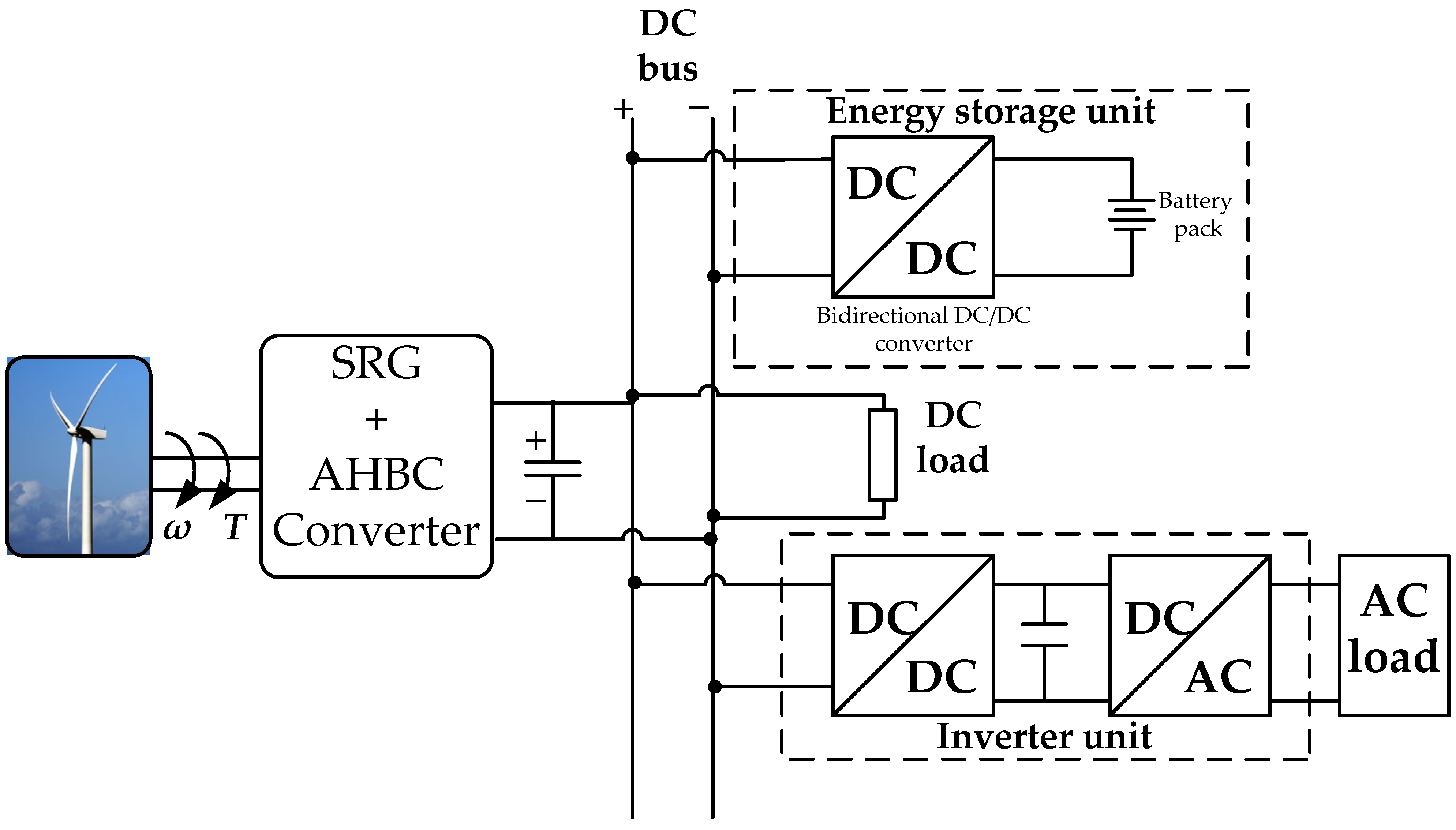
  80. dos Santos Neto, P.J.; dos Santos Barros, T.A.; Catata, E.H.; Ruppert Filho, E. Grid-connected SRG interfaced with bidirectional DC-DC converter in WECS. IEEE Trans. Energy Convers. 2021, 36, 3261–3270. [Google Scholar] [CrossRef]
  81. Barros, T.A.; Neto, P.J.; Paulo Filho, S.N.; Moreira, A.B.; Ruppert, E. Approach for performance optimization of switched reluctance generator in variable-speed wind generation system. Renew. Energy. 2016, 97, 114–128. [Google Scholar] [CrossRef]
  82. dos Santos Neto, P.J.; dos Santos Barros, T.A.; De Paula, M.V.; Ruppert Filho, E.; Vasquez, J.C.; Guerrero, J.M. Wind Distributed System Based on Switched Reluctance Generator Using a Bidirectional DC-DC Converter with Sliding Mode Control. In Proceedings of the IECON 2019-45th Annual Conference of the IEEE Industrial Electronics Society, Lisbon, Portugal, 14–17 October 2019. [Google Scholar] [CrossRef]
  83. Barros, T.A.S.; Ruppert Filho, E. Direct power control for switched reluctance. generator in wind energy. IEEE Lat. Am. Trans. 2015, 13, 123–128. [Google Scholar] [CrossRef] [Green Version]
  84. Hasanien, H.M.; Muyeen, S.M. Speed control of grid-connected switched reluctance generator driven by variable speed wind turbine using adaptive neural network controller. Electr. Power Syst. Res. 2012, 84, 206–213. [Google Scholar] [CrossRef] [Green Version]
  85. Catata, E.O.H.; Neto, P.J.D.S.; De Paula, M.V.; Silveira, J.P.C.; Barros, T.A.D.S.; Ruppert Filho, E. In-Loop Adaptive Filters to Improve the Power Quality of Switched Reluctance Generator in WECS. IEEE Access 2021, 10, 2941–2951. [Google Scholar] [CrossRef]
  86. Chang, Y.C.; Cheng, C.H.; Lu, L.Y.; Liaw, C.M. An experimental switched-reluctance generator based distributed power system. In Proceedings of the XIX International Conference on Electrical Machines-ICEM 2010, Rome, Italy, 6–8 September 2010. [Google Scholar] [CrossRef]
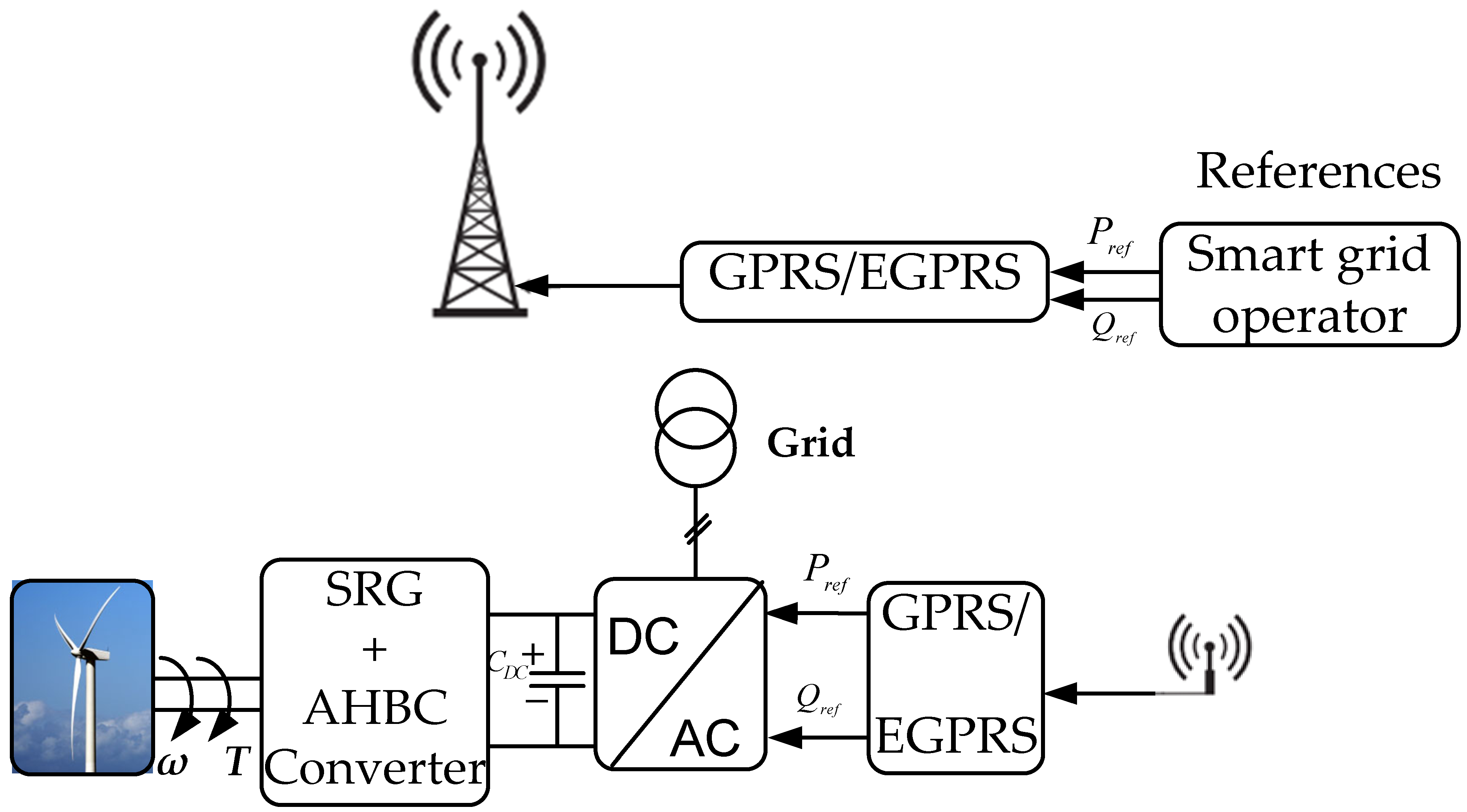
  87. De Oliveira, A.L.; Capovilla, C.E.; Casella, I.R.S.; Azcue-Puma, J.L.; Sguarezi Filho, A.J. Co-simulation of an SRG wind turbine control and GPRS/EGPRS wireless standards in smart grids. IEEE/CAA J. Autom. Sin. 2021, 8, 656–663. [Google Scholar] [CrossRef]
  88. Capovilla, C.E.; Casella, I.R.S.; Sguarezi Filho, A.J.; dos Santos Barros, T.A.; Ruppert Filho, E. Performance of a direct power control system using coded wireless OFDM power reference transmissions for switched reluctance aerogenerators in a smart grid scenario. IEEE Ind. Electron. Mag. 2014, 62, 52–61. [Google Scholar] [CrossRef]
  89. Chen, H.; Xu, D.; Deng, X. Control for power converter of small-scale switched reluctance wind power generator. IEEE Ind. Electron. Mag. 2020, 68, 3148–3158. [Google Scholar] [CrossRef]
  90. Lu, M.Z.; Jhou, P.H.; Liaw, C.M. Wind switched-reluctance generator based microgrid with integrated plug-in energy support mechanism. IEEE Trans. Power Electron. 2020, 36, 5496–5511. [Google Scholar] [CrossRef]
  91. Zhu, Y.; Wu, H.; Zhang, J. Regenerative braking control strategy for electric vehicles based on optimization of switched reluctance generator drive system. IEEE Access 2020, 8, 76671–76682. [Google Scholar] [CrossRef]
  92. Mosaad, M.I.; Elkalashy, N.I.; Ashmawy, M.G. Integrating adaptive control of renewable distributed switched reluctance generation and feeder protection coordination. Electr. Power Syst. Res. 2018, 154, 452–462. [Google Scholar] [CrossRef]
  93. Saad, N.H.; El-Sattar, A.A.; Metally, M.E. Artificial neural controller for torque ripple control and maximum power extraction for wind system driven by switched reluctance generator. Ain Shams Eng. J. 2018, 9, 2255–2264. [Google Scholar] [CrossRef]
  94. Kittiratsatcha, S.; Kerdtuad, P.; Bunlaksananusorn, C. Output Power Control Using Artificial Neural Network for Switched Reluctance Generator. Sens. Mater. 2021, 33, 2427–2444. [Google Scholar] [CrossRef]
  95. Yahia, H.; Liouane, N.; Dhifaoui, R. Differential evolution method-based output power optimisation of switched reluctance generator for wind turbine applications. IET Renew. Power Gener. 2014, 8, 795–806. [Google Scholar] [CrossRef]
  96. Hong, C.M.; Chen, C.H. Enhanced radial fuzzy wavelet neural network with sliding mode control for a switched reluctance wind turbine distributed generation system. Eng. Optim. 2019, 51, 1133–1151. [Google Scholar] [CrossRef]
  97. Magagula, S.G. Power Efficiency Optimization of Switched Reluctance Generator (SRG) Using Power Disturbance Maximum Power Point Tracking (MPPT). Int. J. Electr. Comput. 2017, 9, 445–454. [Google Scholar] [CrossRef] [Green Version]
  98. dos Santos Neto, P.J.; Catata, E.H.; dos Santos Barros, T.A.; Ruppert Filho, E. Optimal Performance of Switched Reluctance Generator in Stand-alone Wind Systems. In Proceedings of the 2021 IEEE Green Technologies Conference (GreenTech), Denver, CO, USA, 7–9 April 2021. [Google Scholar] [CrossRef]
  99. Hajiabadi, H.; Farshad, M.; Shamsinejad, M. Multi-objective optimization and online control of switched reluctance generator for wind power application. Int. J. Ind. Electron. Control Optim. 2021, 4, 33–45. [Google Scholar] [CrossRef]
  100. Li, Z.; Yu, X.; Zhao, L.; Zhao, Y.; Wang, X.; Sun, H. Multi-objective optimization of control parameters of deflectable dual-stator switched reluctance generator at low speed. Electr. Eng. 2022, 1–10. [Google Scholar] [CrossRef]
  101. Bahy, M.; Nada, A.S.; Elbanna, S.H.; Shanab, M.A. Voltage control of switched reluctance generator using grasshopper optimization algorithm. Int. J. Power Electron. Drive Syst. 2020, 11, 75. [Google Scholar] [CrossRef] [Green Version]
  102. Mapa, S.; Gurumoorthy, B. Maximum power extraction from a switched reluctance generator based wind power generating system using optimization techniques. Eng. Rep. 2022, 4, e12457. [Google Scholar] [CrossRef]
  103. Chen, H.; Nie, R.; Gu, J.; Yan, S.; Zhao, R. Performance prediction of switched reluctance generator with time average and small signal models. IEEE/ASME Trans. Mechatron. 2020, 26, 469–479. [Google Scholar] [CrossRef]
Figure 1. Wind power evolution.
Energies 15 04743 g001
Figure 2. Power profile of wind turbines with variable speed.
Energies 15 04743 g002
Figure 3. Characteristics Cp-λ for various values of the pitch angle.
Energies 15 04743 g003
Figure 4. Power–speed characteristics of the wind turbine.
Energies 15 04743 g004
Figure 5. Inductance, voltage, and torque profile of one of the SRG phases.
Energies 15 04743 g005
Figure 6. (a) Aligned position, (b) unaligned position and (c) midway position.
Energies 15 04743 g006
Figure 7. Topology of Asymmetric Half-Bridge Converter (AHBC).
Energies 15 04743 g007
Figure 8. Buck and boost converters. (a) Topology of the boost converter. (b) Topology of the buck converter.
Energies 15 04743 g008
Figure 9. Derishzadeh converter topology.
Energies 15 04743 g009
Figure 10. Vujicic–Calasan SRG power converters. (a) First power converter topologie (PTC1). (b) Second power converter topologie (PTC2).
Energies 15 04743 g010
Figure 11. Active boost power converter.
Energies 15 04743 g011
Figure 12. Accumulator capacitor converter (ACC).
Energies 15 04743 g012
Figure 13. Dong converter topology of a SRG.
Energies 15 04743 g013
Figure 14. Variable DC link converter (CvDC).
Energies 15 04743 g014
Figure 15. Schematic diagram of direct power control.
Energies 15 04743 g015
Figure 16. Block diagram of direct power control based on PR controller.
Energies 15 04743 g016
Figure 17. The SR power generation system with: (a) FW-PT and (b) CC-PT.
Energies 15 04743 g017aEnergies 15 04743 g017b
Figure 18. The bloc diagram of the sliding mode variable structure Controller.
Energies 15 04743 g018
Figure 19. Torque Sharing Function (TSF) control scheme.
Energies 15 04743 g019
Figure 20. Complete system of SRG connected to single-phase network.
Energies 15 04743 g020
Figure 21. A SRG connected to the grid in WECS.
Energies 15 04743 g021
Figure 22. The bloc diagram of voltage source converter (VSC) control.
Energies 15 04743 g022
Figure 23. Wireless power control system.
Energies 15 04743 g023
Figure 24. Small-scale wind power system based on the integrated energy storage system.
Energies 15 04743 g024
Table 1. Comparison of generators in WECS.
Generator TypeAdvantageDisadvantage
Induction Generators (IG)Suitable for use in DC energy storage
Good reliability
Brush structure
A lot of maintenance
Low efficiency
Doubly Fed Induction
Generator (DFIG)
High power quality
Convenient maintenance
Partial-scale power converters
Low reliability
Complicate practical implementation
Permanent Magnet Synchronous Generator (PMSG)High Efficiency
Small volume
High power density
Poor fault tolerance
Poor voltage regulation performance
High cost of the full-scale power converters
Switched Reluctance Generator (SRG)Good fault tolerance performance
Simple manufacture
Flexible control
High torque density
Low cost
Low maintenance requirement
Torque ripple
Acoustic noise
Need special converter topology
Table 2. Comparison of different converter topologies.
TopologySwitch NumbersDiode NumbersSensor PositionFault
Tolerance
Control
Complexity
Reference
Asymmetric half bridge converter2n2nYesHighLow[33,45]
Buck and boost convertersnnYesMediumLow[30]
Derishzadeh converter topologyn2nYesHighMedium[37]
PTC1/ PTC204nNoMediumHigh[37,39]
Active boost power converter2n + 12n + 2YesHighLow[40]
Accumulator capacitor converter (ACC)n + 1n + 1YesMediumMedium[41,42]
Dong converter 2n + 12nYesHighLow[43]
Converter with
variable DC link (CvDC)
2n + 12n + 1YesMediumHigh[44]
Table 3. Comparison of different SRG control methods.
Control MethodsAdvantageDisadvantageReference
Proportional Integral (PI)Easy to implement and improves the steady-state performance. Long settling time and controller parameters cannot be optimized with different operating conditions[33,35,57]
Sliding Mode (SM)Enhance the dynamic characteristics of SRG.
Rapid response.
High frequency vibrations of the controlled system, which degrades the performance and may lead to instability.[49,64,65]
Proportional Resonant (PR)Zero overshoot and fast transient response in SRG power control.
Minimization of voltage ripples.
The difficulty of adjusting their parameters due to the non-linearity of SRG.[53,54]
Modified Angle Position Control (MAPC)The optimal coupling turn-on and turn-off angle improve the efficiency.Higher the torque ripple.[55]
Continuous Conduction Mode (CCM)/Discontinuous (CM)Fast transient response, simplicity of design and implementation.CCM is only effective at high speed.
The estimation error of the rotor position may cause a significant reduction on SRG performance.
[56,62,63]
Proportional, Integral and Derivative (PID)Improve the transient performance of SRG control.The difficulty of adjusting their parameters due to the non-linearity of SRG.[58]
Fly-Wheeling Pulse Train (FW-PT)Simple circuit implementation.
The absence of network compensation and fast response time.
Reduction in SRG efficiency.[59]
Capacitor Current Pulse Train (CC-PT)Simple circuit structure.
Zero overshoot and excellent steady-state and transient response characteristics.
Low frequency oscillation.[61]
Fuzzy Inference System (FIS)Used when the systems are highly non-linear.Unavoidable overshoot and larger steady-state error.[67]
Peak-Current EstimationImprove the steady-state peak-current of the SRGThe circuit model is applicable to a specific interval.[68]
Model Predictive Control (MPC)Fast response with low ripple and very low overshoot of the SRG phase current.Complex control.
Cumbersome calculation.
Variable switching frequency.
Model dependent
[69]
Torque Sharing Function (TSF)Reduce torque ripple.
Improve system efficiency.
Minimize copper losses.
The current is difficult to track at high speed.[74]
Publisher’s Note: MDPI stays neutral with regard to jurisdictional claims in published maps and institutional affiliations.

