
Intelligent Controlled DSTATCOM for Power Quality Enhancement


Abstract
:1. Introduction
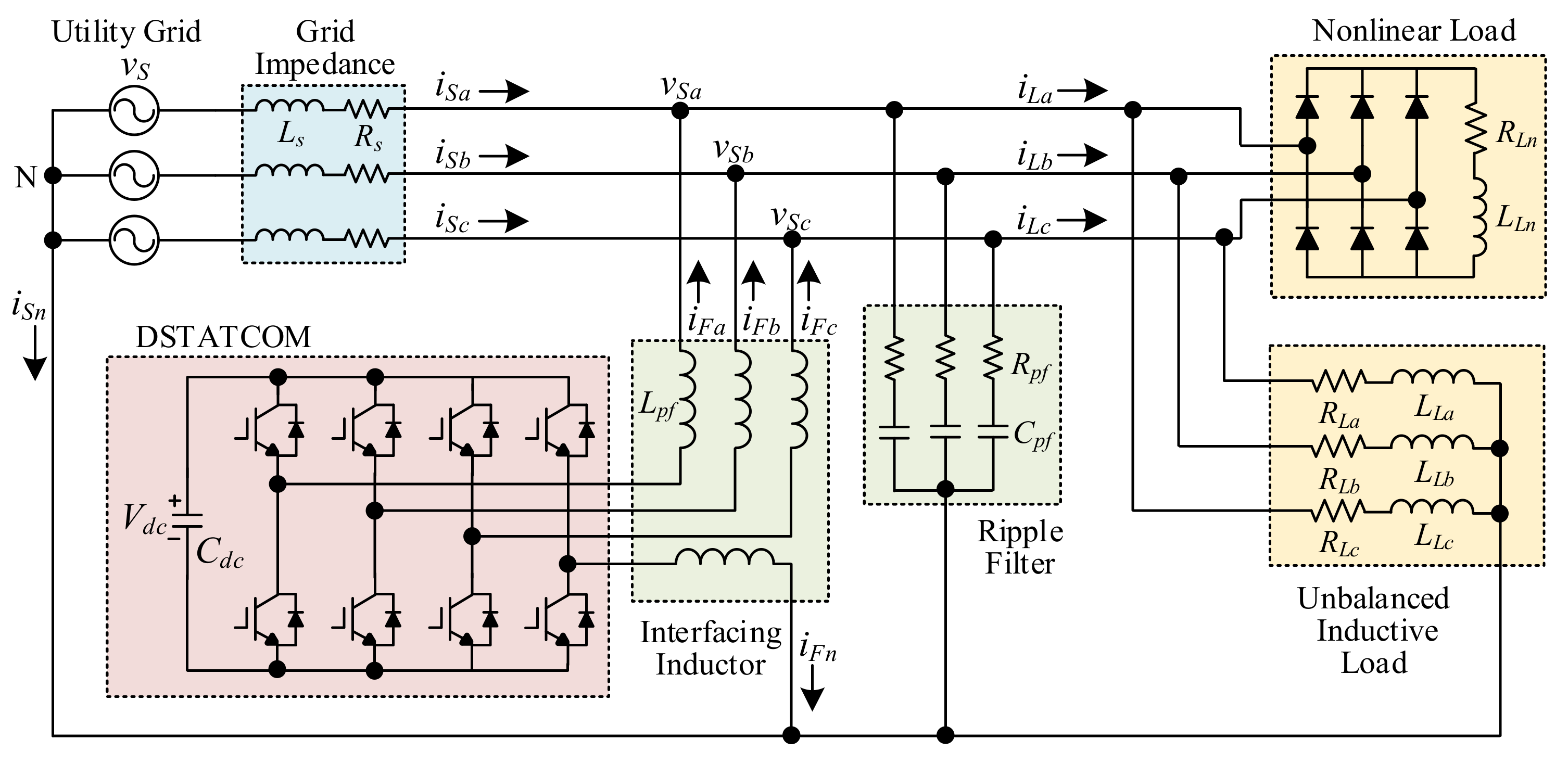
2. Three-Phase Four-Wire DSTATCOM
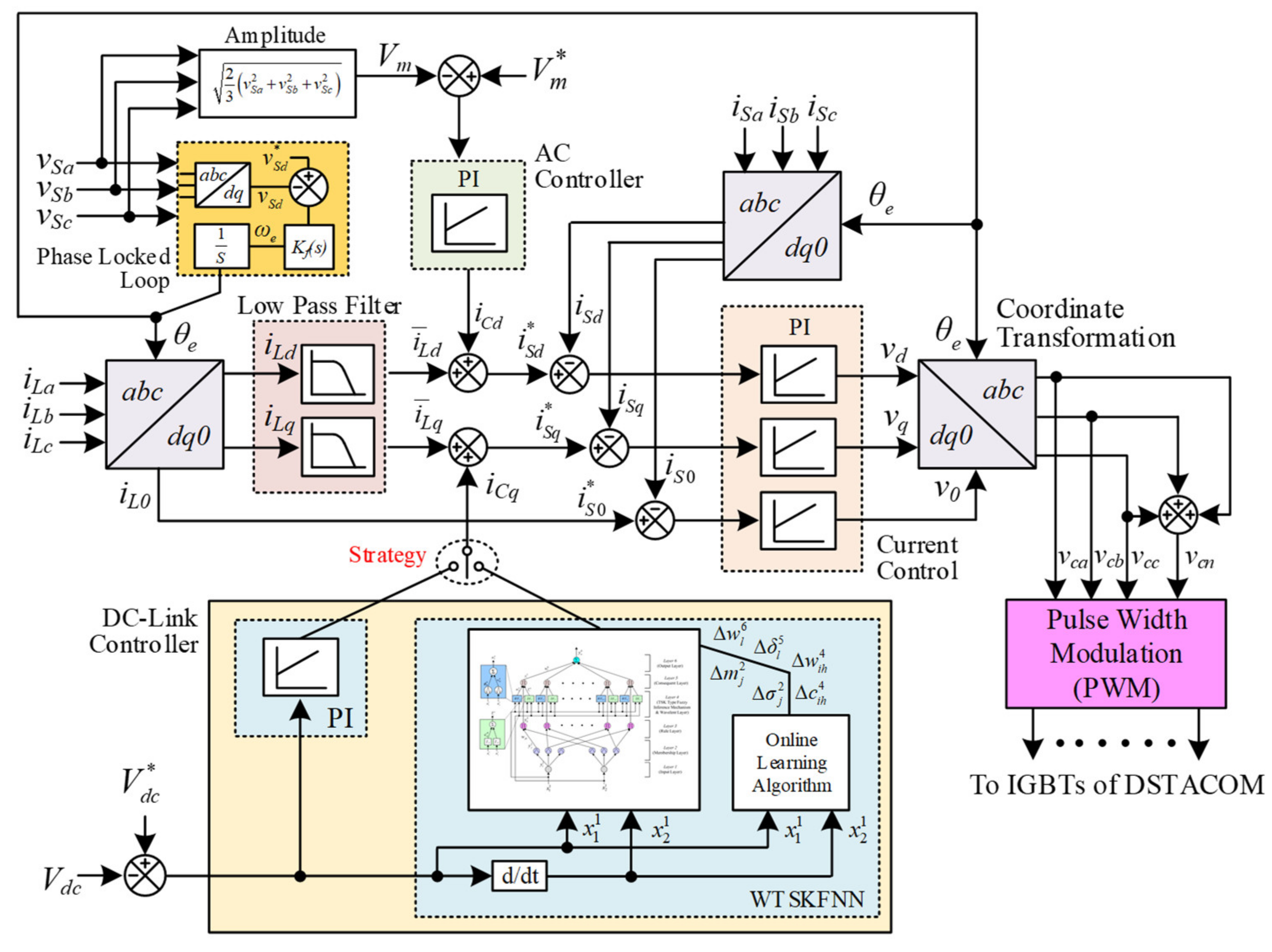
3. Intelligent WTSKFNN Controller
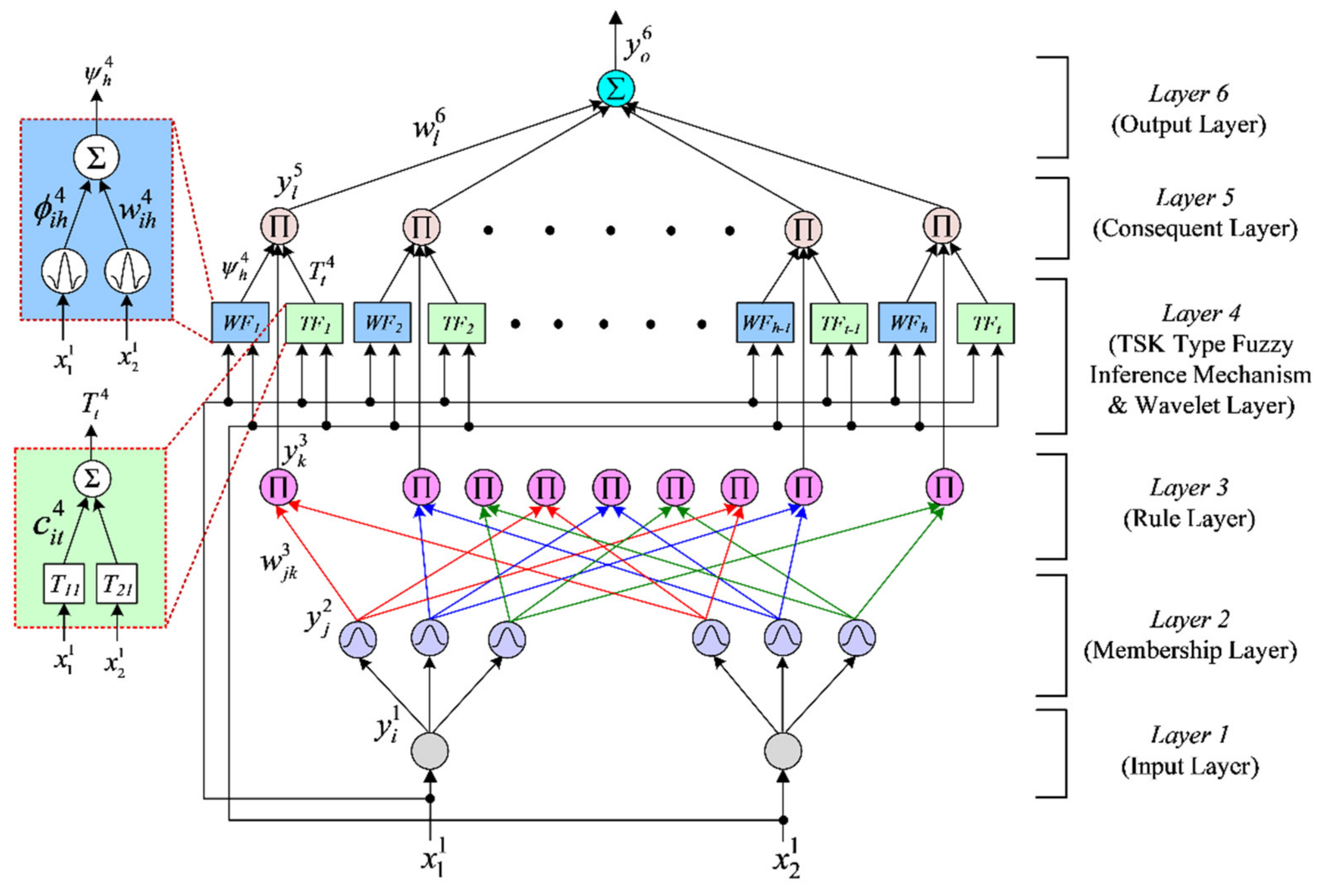
3.1. Network Structure
- Input Layer:
- 2.
- Membership Layer:
- 3.
- Ruler Layer:
- 4.
- TSK-Type Fuzzy Inference Mechanism and Wavelet layer:
- 5.
- Consequent Layer:
- 6.
- Output Layer:
3.2. Online Learning Algorithm
- Output Layer:
- 2.
- Consequent Layer:
- 3.
- TSK-Type Fuzzy Inference Mechanism and Wavelet Layer:
- 4.
- Ruler Layer:
- 5.
- Membership Layer:
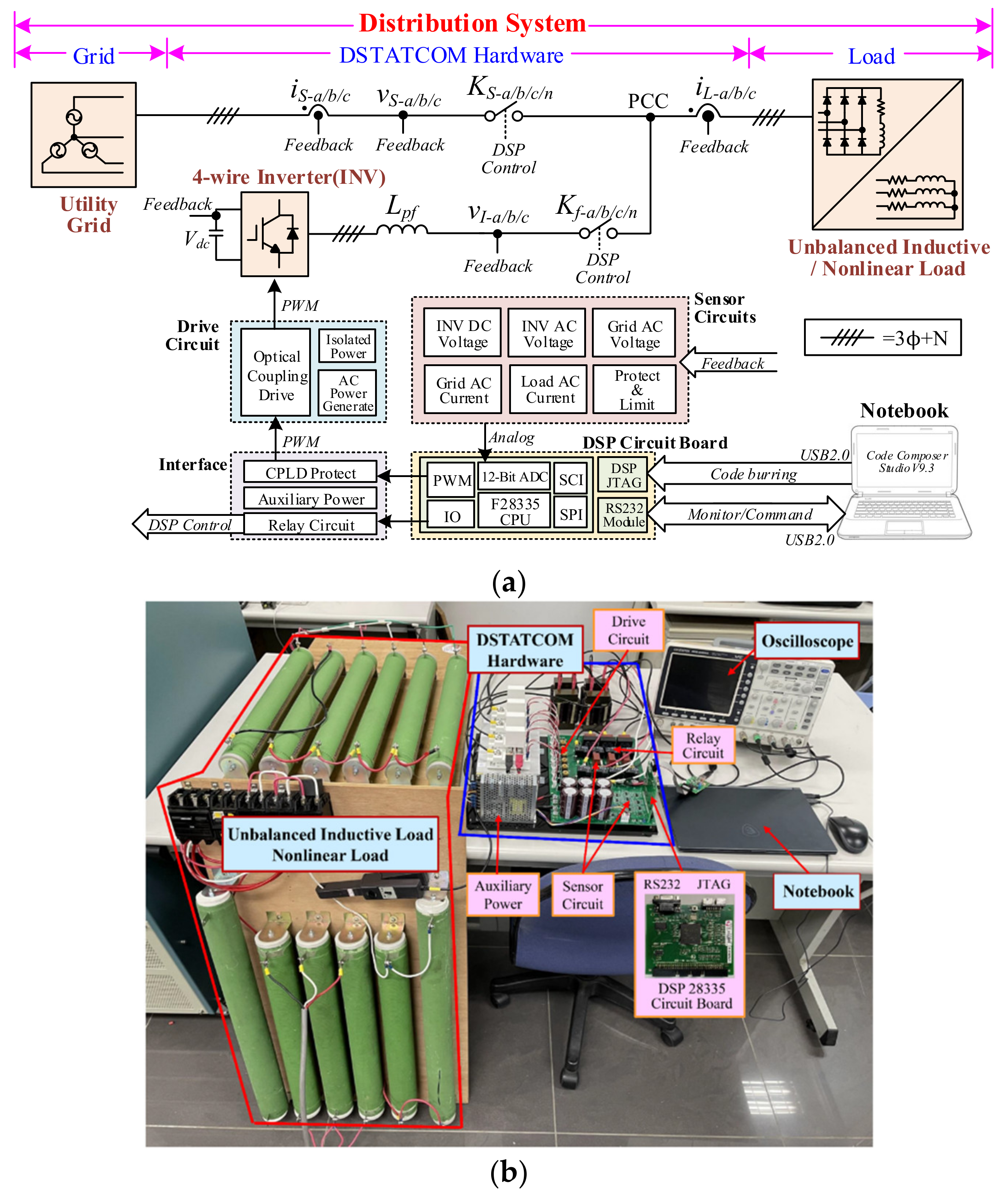
4. Experimental Results
5. Conclusions
Author Contributions
Funding
Institutional Review Board Statement
Informed Consent Statement
Data Availability Statement
Conflicts of Interest
Nomenclature
| Three-phase grid voltages. | |
| Grid impedance. | |
| Nonlinear load. | |
| Phase-a unbalanced inductive load. | |
| Phase-b unbalanced inductive load. | |
| Phase-c unbalanced inductive load. | |
| DC-link capacitor. | |
| Interfacing Inductor. | |
| Ripple Filter. | |
| Three-phase compensation currents of DSTATCOM. | |
| Four-wire compensation current of DSTATCOM. | |
| Three-phase load currents. | |
| dq0-axis load currents. | |
| DC current components of the dq-axis load currents. | |
| Transfer function of the low pass filter. | |
| Angular cut-off frequency. | |
| Damping ratio. | |
| Gain of the low pass filter. | |
| d-axis grid voltage. | |
| d-axis grid voltage command. | |
| Electrical angular frequency. | |
| Electrical angle. | |
| Voltage amplitude of three-phase grid voltages. | |
| Voltage amplitude command of three-phase grid voltages. | |
| Voltage amplitude control current. | |
| DC-link voltage. | |
| DC-link voltage command. | |
| DC-link control current. | |
| d-axis current command. | |
| q-axis current command. | |
| zero axis current command. | |
| Three-phase grid currents. | |
| dq0-axis grid currents. | |
| dq0-axis voltage commands. | |
| PWM switching signals of three-phase control commands. | |
| PWM switching signals of the forth control command. | |
| Input of WTSKFNN. | |
| DC-link voltage error. | |
| Derivative of DC-link voltage error. | |
| Number of iterations. | |
| Input linguistic variable to node of membership layer. | |
| Standard deviation of Gaussian function. | |
| Mean of Gaussian function. | |
| Output of membership layer. | |
| Connected weight between membership layer and rule layer. | |
| Output of rule layer. | |
| Wavelet functions. | |
| ith in the hth term wavelet output to the node of wavelet sum layer. | |
| Connected weight of layer. | |
| Output of layer. | |
| TSK type fuzzy inference mechanism functions. | |
| Connected weight of layer. | |
| Output of layer. | |
| Output of consequent Layer. | |
| Connected weight between consequent layer and output layer. | |
| Output of WTSKFNN. | |
| Energy function. | |
| Error term of output layer. | |
| Error term of consequent layer. | |
| Error term of layer. | |
| Error term of layer. | |
| Error term of rule layer. | |
| Error term of membership layer. | |
| Learning rate of connected weight between consequent layer and output layer. | |
| Learning rate of connected weight of functions. | |
| Learning rate of connected weight of functions. | |
| Learning rate of mean of Gaussian function. | |
| Learning rate of standard deviation of Gaussian function. |
References
- Lin, L.; He, J.; Xu, C. Analysis on circulating current and split capacitor voltage balance for modular multilevel converter based three-phase four-wire split capacitor DSTATCOM. J. Mod. Power Syst. Clean Energy 2021, 9, 657–667. [Google Scholar] [CrossRef]
- Kumar, C.; Mishra, M.K.; Mekhilef, S. A new voltage control strategy to improve performance of DSTATCOM in electric grid. CES Trans. Electr. Mach. Syst. 2020, 4, 295–302. [Google Scholar] [CrossRef]
- Xu, C.; Dai, K.; Chen, X.; Kang, Y. Unbalanced PCC voltage regulation with positive- and negative-sequence compensation tactics for MMC-DSTATCOM. IET Power Electron. 2016, 9, 2846–2858. [Google Scholar] [CrossRef]
- Prasad, K.K.; Myneni, H.; Siva Kumar, G. Power quality improvement and PV power injection by DSTATCOM with variable DC link voltage control from RSC-MLC. IEEE Trans. Sustain. Energy 2019, 10, 876–885. [Google Scholar] [CrossRef]
- Mishra, S.; Ray, P.K. Power quality improvement using photovoltaic fed DSTATCOM based on JAYA optimization. IEEE Trans. Sustain. Energy 2016, 7, 1672–1680. [Google Scholar] [CrossRef]
- Pandu, S.B.; Sundarabalan, C.K.; Srinath, N.S.; Santhana Krishnan, T.; Soorya Priya, G.; Balasundar, C.; Sharma, J.; Soundarya, G.; Siano, P.; Alhelou, H.H. Power quality enhancement in sensitive local distribution grid using interval type-II fuzzy logic controlled DSTATCOM. IEEE Access 2021, 9, 59888–59899. [Google Scholar] [CrossRef]
- Tan, K.H.; Lin, F.J.; Chen, J.H. DC-link voltage regulation using RPFNN-AMF for three-phase active power filter. IEEE Access 2018, 6, 37454–37463. [Google Scholar] [CrossRef]
- Srinivas, M.; Hussain, I.; Singh, B. Combined LMS–LMF-based control algorithm of DSTATCOM for power quality enhancement in distribution system. IEEE Trans. Ind. Electron. 2016, 63, 4160–4168. [Google Scholar] [CrossRef]
- Patel, S.K.; Arya, S.R.; Maurya, R. Nonlinear adaptive volterra filter for control of distribution static compensator. IEEE J. Emerg. Sel. Top. Power Electron. 2017, 5, 559–567. [Google Scholar] [CrossRef]
- Patel, S.K.; Arya, S.R.; Maurya, R.; Babu, B.C. Control scheme for DSTATCOM based on frequency-adaptive disturbance observer. IEEE J. Emerg. Sel. Top. Power Electron. 2018, 6, 1345–1354. [Google Scholar] [CrossRef]
- Singh, B.; Solanki, J. A comparison of control algorithms for DSTATCOM. IEEE Trans. Ind. Electron. 2009, 56, 2738–2745. [Google Scholar] [CrossRef]
- Czarnecki, L.S. Instantaneous reactive power p-q theory and power properties of three-phase systems. IEEE Trans. Power Deliv. 2006, 21, 362–367. [Google Scholar] [CrossRef]
- Freitas, W.; Morelato, A.; Xu, W.; Sato, F. Impacts of AC generators and DSTATCOM devices on the dynamic performance of distribution systems. IEEE Trans. Power Deliv. 2005, 20, 1493–1501. [Google Scholar] [CrossRef]
- Singh, B.; Jayaprakash, P.; Kothari, D.P. A t-connected transformer and three-leg VSC based DSTATCOM for power quality improvement. IEEE Trans. Power Electron. 2008, 23, 2710–2718. [Google Scholar] [CrossRef]
- Bagheri, M.; Nurmanova, V.; Abedinia, O.; Naderi, M.S. Enhancing power quality in microgrids with a new online control strategy for DSTATCOM using reinforcement learning algorithm. IEEE Access 2018, 6, 38986–38996. [Google Scholar] [CrossRef]
- Kumar, A.; Kumar, P. Power quality improvement for grid-connected PV system based on distribution static compensator with fuzzy logic controller and UVT/ADALINE-based least mean square controller. J. Mod. Power Syst. Clean Energy 2021, 9, 1289–1299. [Google Scholar] [CrossRef]
- Chawda, G.S.; Shaik, A.G. Enhancement of wind energy penetration levels in rural grid using ADALINE-LMS controlled distribution static compensator. IEEE Trans. Sustain. Energy 2022, 13, 135–145. [Google Scholar] [CrossRef]
- Khoshooei, A.; Moghani, J.S.; Candela, I.; Rodriguez, P. Control of D-STATCOM during unbalanced grid faults based on DC voltage oscillations and peak current limitations. IEEE Trans. Ind. Appl. 2018, 54, 1680–1690. [Google Scholar] [CrossRef] [Green Version]
- Zhou, X.; Zhong, W.; Ma, Y.; Guo, K.; Yin, J.; Wei, C. Control strategy research of D-STATCOM using active disturbance rejection control based on total disturbance error compensation. IEEE Access 2021, 9, 50138–50150. [Google Scholar] [CrossRef]
- Woo, J.H.; Wu, L.; Lee, S.M.; Park, J.B.; Roh, J.H. D-STATCOM d-q axis current reference control applying DDPG algorithm in the distribution system. IEEE Access 2021, 9, 145840–145851. [Google Scholar] [CrossRef]
- Tan, K.H. Squirrel cage induction generator system using wavelet petri fuzzy neural network control for wind power applications. IEEE Trans. Power Electron. 2016, 31, 5242–5254. [Google Scholar] [CrossRef]
- Lin, F.J.; Hung, Y.C.; Ruan, K.C. An intelligent second-order sliding-mode control for an electric power steering system using a wavelet fuzzy neural network. IEEE Trans. Fuzzy Syst. 2014, 22, 1598–1611. [Google Scholar] [CrossRef]
- Yilmaz, S.; Oysal, Y. Fuzzy wavelet neural network models for prediction and identification of dynamical systems. IEEE Trans. Neural Netw. 2010, 21, 1599–1609. [Google Scholar] [CrossRef]
- Lin, F.J.; Tan, K.H.; Luo, W.C.; Xiao, G.D. Improved LVRT performance of PV power plant using recurrent wavelet fuzzy neural network control for weak grid conditions. IEEE Access 2020, 8, 69346–69358. [Google Scholar] [CrossRef]
- El-Sousy, F.F.M.; Amin, M.M.; Mohammed, O.A. Robust optimal control of high-speed permanent-magnet synchronous motor drives via self-constructing fuzzy wavelet neural network. IEEE Trans. Ind. Appl. 2021, 57, 999–1013. [Google Scholar] [CrossRef]
- Lin, F.J.; Liao, J.C.; Chen, C.I.; Chen, P.R.; Zhang, Y.M. Voltage restoration control for microgrid with recurrent wavelet petri fuzzy neural network. IEEE Access 2022, 10, 12510–12529. [Google Scholar] [CrossRef]
- Qin, B.; Nojima, Y.; Ishibuchi, H.; Wang, S. Realizing deep high-order TSK fuzzy classifier by ensembling interpretable zero-order TSK fuzzy subclassifiers. IEEE Trans. Fuzzy Syst. 2021, 29, 3441–3455. [Google Scholar] [CrossRef]
- Lin, F.J.; Lu, K.C.; Ke, T.H.; Yang, B.H.; Chang, Y.R. Reactive power control of three-phase grid-connected PV system during grid faults using Takagi–Sugeno–Kang probabilistic fuzzy neural network control. IEEE Trans. Ind. Electron. 2015, 62, 5516–5528. [Google Scholar] [CrossRef]
- Yen, J.; Wang, L.; Gillespie, C.W. Improving the interpretability of TSK fuzzy models by combining global learning and local learning. IEEE Trans. Fuzzy Syst. 1998, 6, 530–537. [Google Scholar] [CrossRef]
- Lin, F.J.; Hung, Y.C.; Tsai, M.T. Fault-tolerant control for six-phase PMSM drive system via intelligent complementary sliding-mode control using TSKFNN-AMF. IEEE Trans. Ind. Electron. 2013, 60, 5747–5762. [Google Scholar] [CrossRef]
- Zhang, T.; Deng, Z.; Ishibuchi, H.; Pang, L.M. Robust TSK fuzzy system based on semisupervised learning for label noise data. IEEE Trans. Fuzzy Syst. 2021, 29, 2145–2157. [Google Scholar] [CrossRef]


| Symbol | Parameters | Values |
|---|---|---|
| VS | System Voltage | 220 Vrms(L-L), 60 Hz |
| Vdc | DC-Link Voltage | 450 V |
| Cdc | DC-Link Capacitor | 2820 uF |
| Lpf | Interfacing Inductor | 3 mH |
| Cpf | Ripple Filter | 10 uF |
| fsw | Switching Frequency | 18 kHz |
| RL-a,b,c, LL-a,b,c | Unbalanced Inductive Load 1 | RLa: 65 Ω, LLa: 40 mH |
| Unbalanced Inductive Load 2 | RLb: 30 Ω, LLb: 50 mH | |
| RLc: 120 Ω, LLc: 30 mH | ||
| RLa: 20 Ω, LLa: 50 mH | ||
| RLb: 10 Ω, LLb: 30 mH | ||
| RLc: 50 Ω, LLc: 40 mH | ||
| RLn, LLn | Nonlinear Load 1 | 75 Ω, 1 mH |
| Nonlinear Load 2 | 50 Ω, 1 mH | |
| RL1 | Unbalanced Inductive Load 1 and Nonlinear Load 1 | |
| RL2 | Unbalanced Inductive Load 2 and Nonlinear Load 2 | |
| RL3 | RL1 and RL2 | |
| Type of Load | Strategy | UR (%) | THD (%) | Power Factor | ||||
|---|---|---|---|---|---|---|---|---|
| iS-a,b,c | iSa | iSb | iSc | iSa | iSb | iSc | ||
| RL1 | Without Compensation | 37.65 | 19.34 | 17.46 | 25.94 | 0.957 | 0.946 | 0.964 |
| Traditional (PI) | 12.57 | 4.34 | 4.38 | 4.39 | 0.996 | 0.997 | 0.996 | |
| FNN | 9.44 | 3.91 | 4.05 | 4.01 | 0.997 | 0.997 | 0.998 | |
| WTSKFNN (Proposed) | 5.71 | 3.67 | 3.74 | 3.71 | 0.998 | 0.997 | 0.998 | |
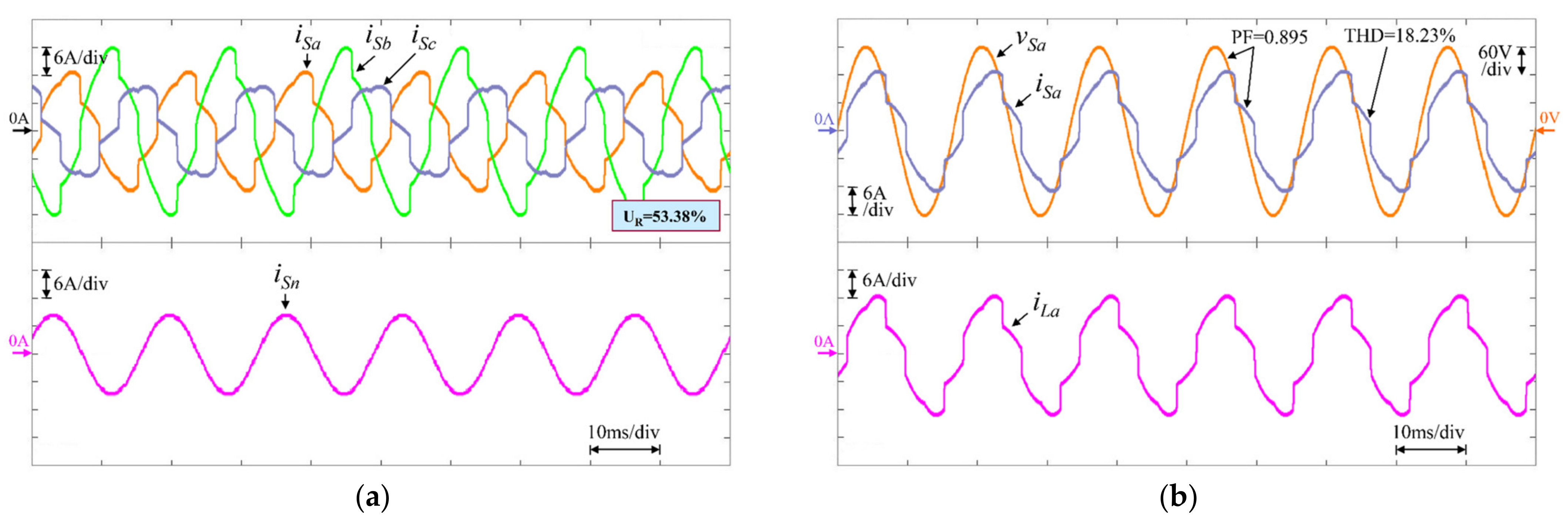
| RL2 | Without Compensation | 53.38 | 18.23 | 12.68 | 23.46 | 0.895 | 0.834 | 0.954 |
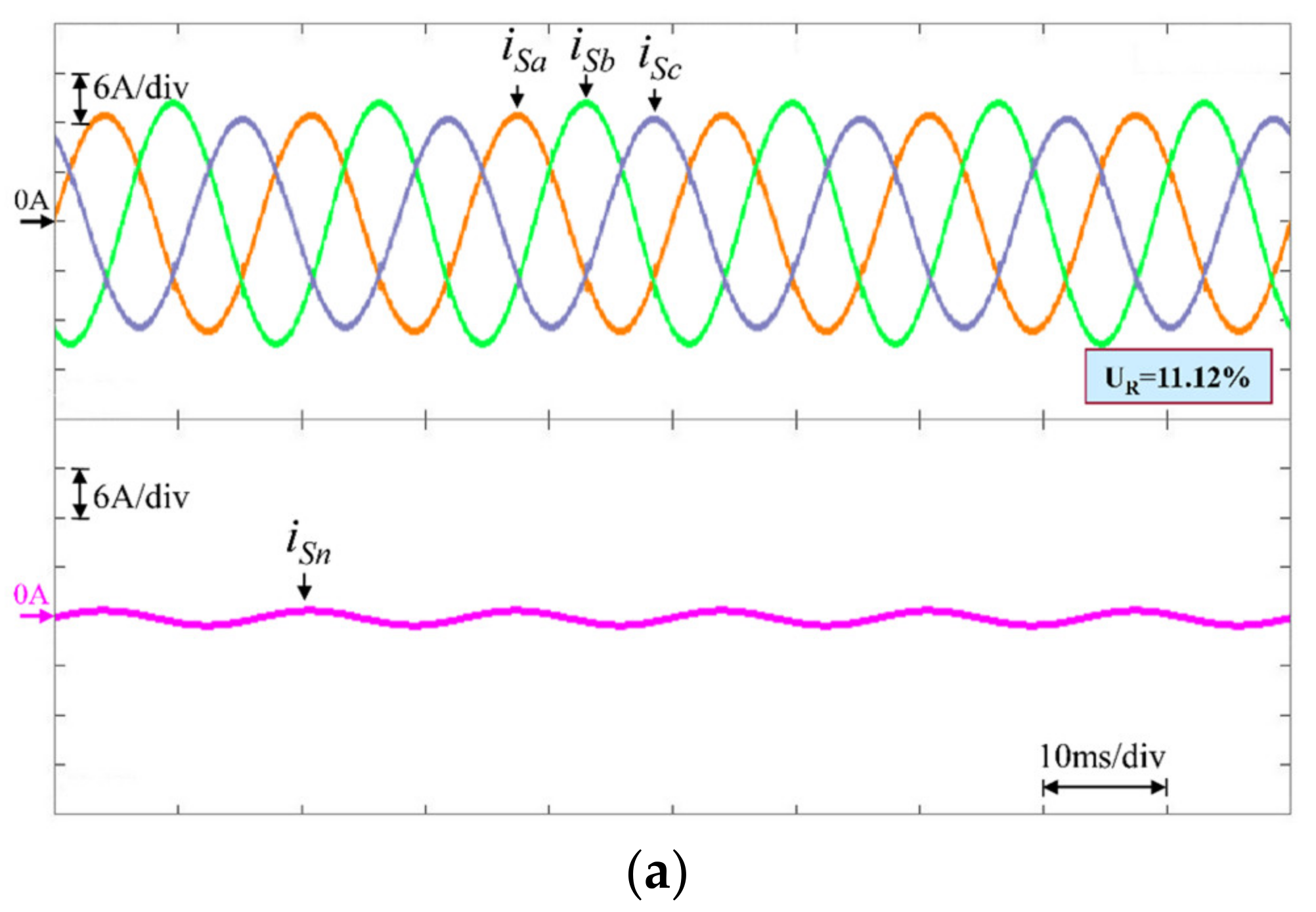
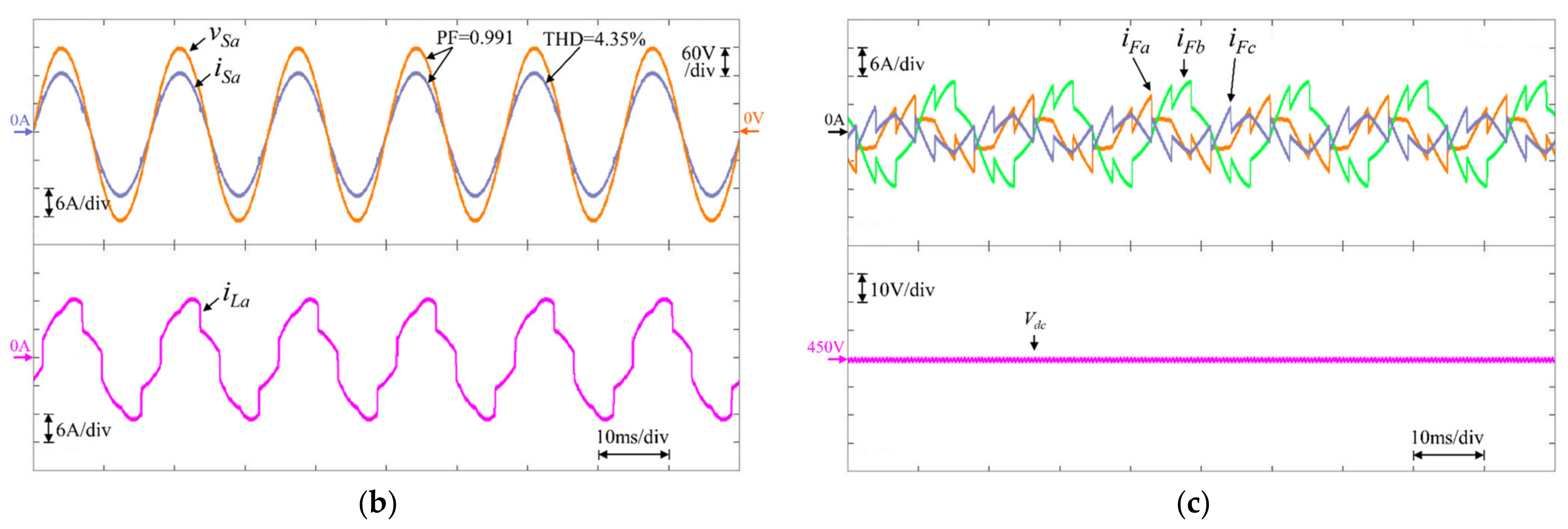
| Traditional (PI) | 11.12 | 4.35 | 4.27 | 4.43 | 0.991 | 0.992 | 0.991 | |
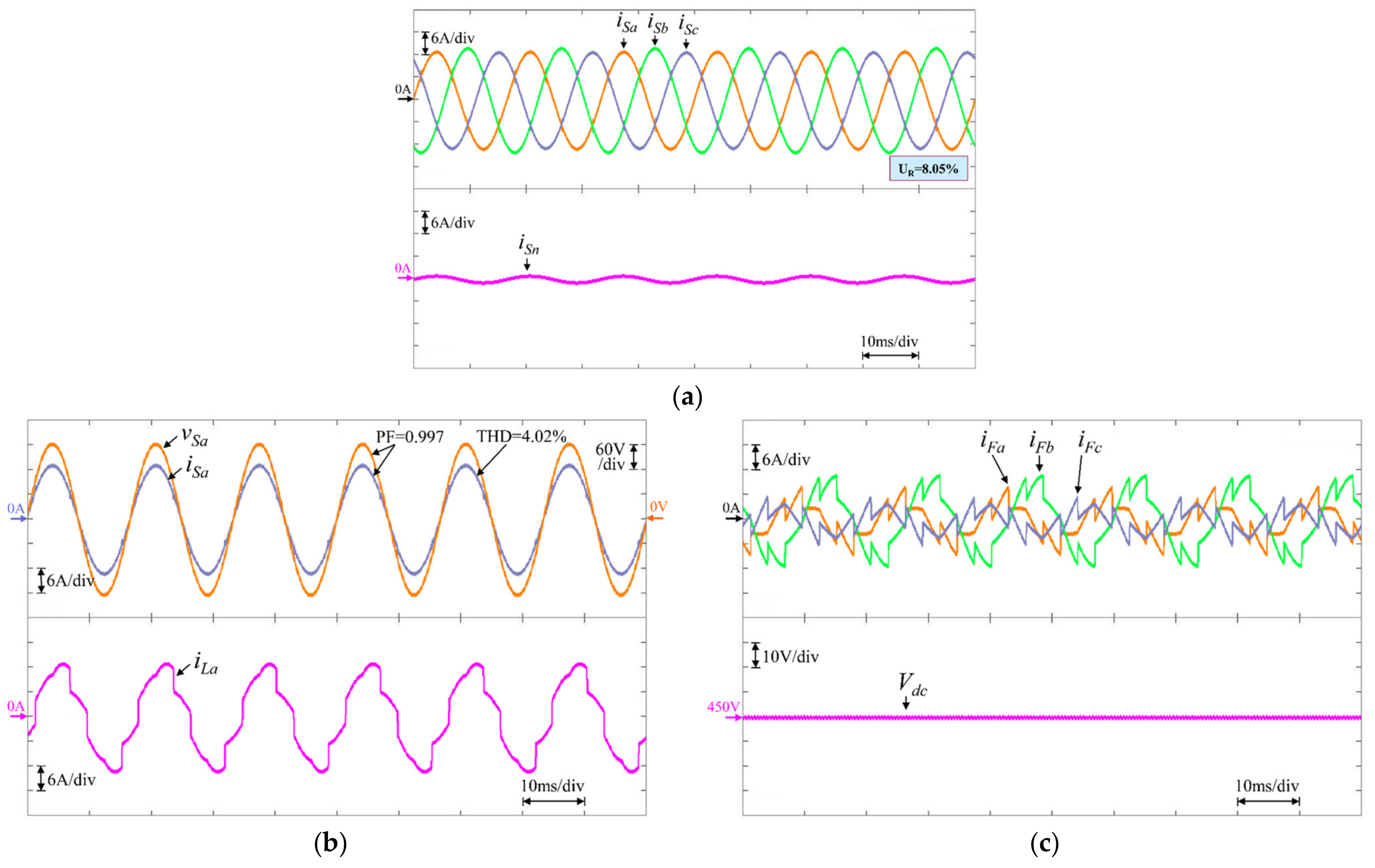
| FNN | 8.05 | 4.02 | 3.95 | 4.05 | 0.997 | 0.998 | 0.996 | |
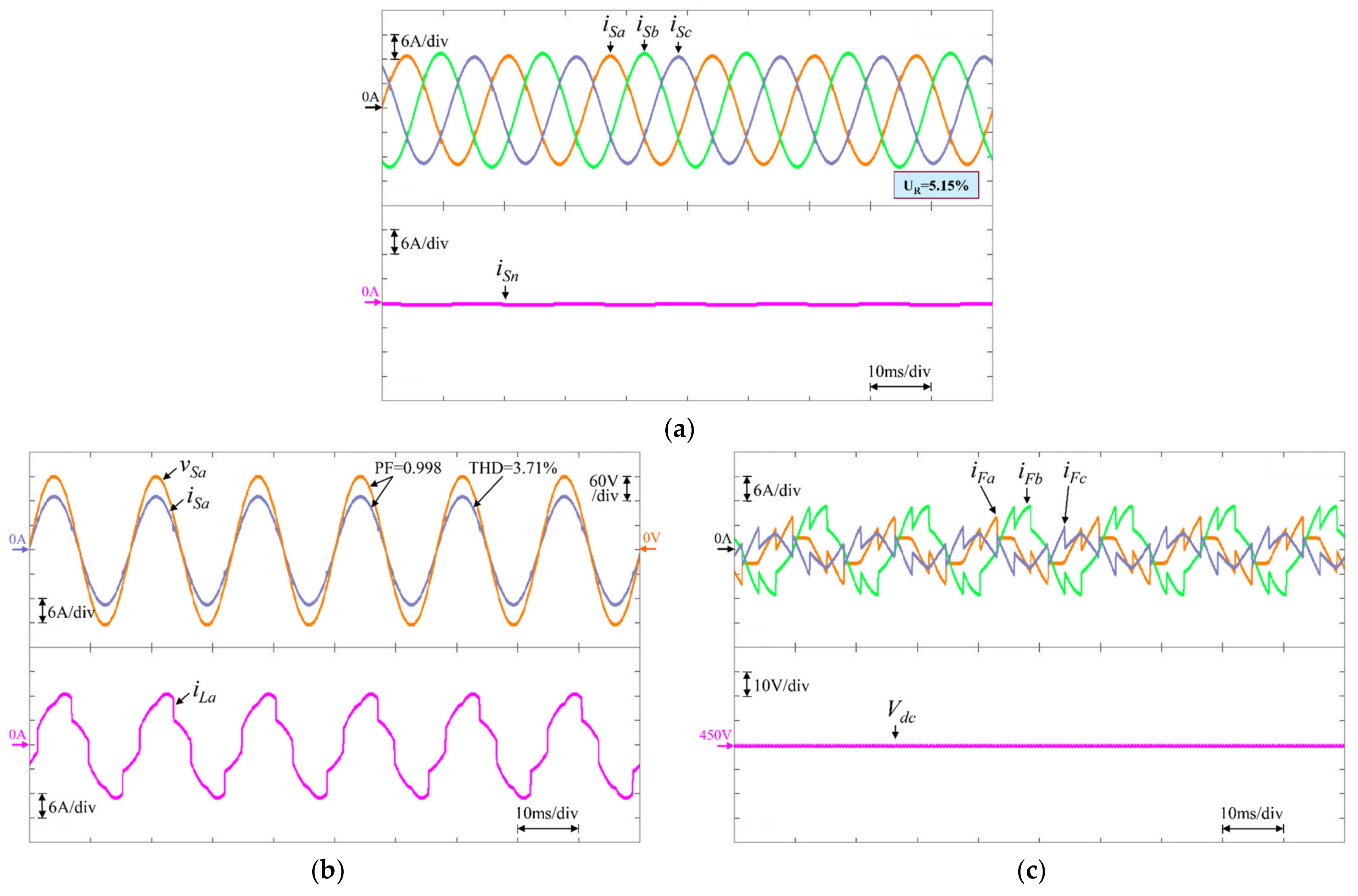
| WTSKFNN (Proposed) | 5.15 | 3.71 | 3.77 | 3.67 | 0.998 | 0.998 | 0.998 | |
| Strategy | PI | FNN | Proposed WTSKFNN |
|---|---|---|---|
| Total Operation Cycles | 1605 | 11,865 | 16,725 |
| Execution Time | 0.0107 ms | 0.0791 ms | 0.1115 ms |
Publisher’s Note: MDPI stays neutral with regard to jurisdictional claims in published maps and institutional affiliations. |
© 2022 by the authors. Licensee MDPI, Basel, Switzerland. This article is an open access article distributed under the terms and conditions of the Creative Commons Attribution (CC BY) license (https://creativecommons.org/licenses/by/4.0/).
Share and Cite
Chen, J.-H.; Tan, K.-H.; Lee, Y.-D. Intelligent Controlled DSTATCOM for Power Quality Enhancement. Energies 2022, 15, 4017. https://doi.org/10.3390/en15114017
Chen J-H, Tan K-H, Lee Y-D. Intelligent Controlled DSTATCOM for Power Quality Enhancement. Energies. 2022; 15(11):4017. https://doi.org/10.3390/en15114017
Chicago/Turabian StyleChen, Jun-Hao, Kuang-Hsiung Tan, and Yih-Der Lee. 2022. "Intelligent Controlled DSTATCOM for Power Quality Enhancement" Energies 15, no. 11: 4017. https://doi.org/10.3390/en15114017