1. Introduction
Industrial processes are accountable for about 26% of the European Union’s (EU’s) final energy consumption, and are characterized by a multitude of energy losses, including heat streams rejected to the environment as exhaust gases or effluents occurring at various temperature levels [
1]. Industrial waste heat is the energy generated in industrial processes that is not put into practical use, lost, wasted, and discarded into the environment. Reducing or recovering such energy flows can undoubtedly contribute to better environmental performance, as well as to reduced overall cost of the manufacturing of goods. It is thus desirable to recover and reuse as much wasted heat as possible; this phenomenon is called waste heat recovery (WHR), which can be employed not only in industrial, but also in domestic applications. The present study, however, deals with industrial applications. Beyond WHR alone, a more generalized model for wasted heat—beyond the scope of the present study but worth mentioning—could include the use of a thermo-economic indicator, based on thermodynamic optimization and ecological evaluations [
2,
3].
Undeniably, increasing further WHR adoption by industries can lead to: (i) higher energy efficiency for a sustainable industry; (ii) improved industrial competitiveness; (iii) promotion of a new European supply chain for exporting WHR technologies; and (iv) capital saving and jobs creation. The benefits of WHR are of an economic, resource (fuel) saving, and environmental nature, namely: (i) conversion of heat into useful forms of energy; (ii) generation of electricity and mechanical work; (iii) reductions in cooling needs; (iv) fuel savings; (v) increases in production; (vi) reductions in capital and investment costs in cases of new facilities; and (vii) reductions in greenhouse gas emissions.
The overall energy consumption of the European Union (EU) (including the United Kingdom) in 2018 was 3218 TWh, with the highest consumptions being 711 TWh, 342 TWh, 304 TWh, and 282 TWh in Germany, France, Italy, and the United Kingdom, respectively. Regarding the industrial sectors, Chemical and Petrochemical, Iron and Steel, Paper, Pulp and Print and Nonmetallic Minerals had the highest consumptions, at 597 TWh, 596 TWh, 394 TWh, and 386 TWh respectively. More details about this analysis can be found, for example, in [
4]. The EU energy consumption by country and by industrial sector for the year 2020 can be found in [
5].
Moreover, the main relevant industries and their percentage waste heat potentials (according to [
6]) were as follows: Iron and Steel—I&S (11.4%); Nonmetallic Minerals—NMM (11.4%); Textile and Leather—T&L (11.0%); Chemical and Petrochemical—C&P (11.0%); Paper; Pulp; and Print—PPP (10.6%); Nonferrous Metals—NFM (9.6%); Food and Tobacco—F&T (8.6%); Wood and Wood Products—WWP (6.0%); and all others, including Construction—C, Machinery—M, Mining and Quarrying—M&Q, Transport Equipment—TE, and Not Specified—NS (20.4%).
The WHR potential can be classified according to the temperature range. The above results ignored the temperature range of heat wasted in each industry, as expressed in [
7], as follows: low temperature (LT) < 100 °C, 12.60%; medium temperature (MT) 100–400 °C, 6%; high temperature (MT) ≥ 400 °C, 11.40%. Thus, these presented a rough estimate of the WHR potential, which was close to the results obtained in [
8], which carried out a more detailed analysis, and [
6].
Based on the methodology followed in [
8] for the estimation of the WHR potential, the countries with the highest estimated potential per industry are as follows: F&T: Germany 5.1 TWh, France 4.8 TWh, Italy 2.8 TWh; I&S: Germany 17 TWh, France 7 TWh, Italy 6.8 TWhl; T&L: Italy 1.4 TWh, United Kingdom 0.8 TWh, Germany 0.6 TWh; NFM: Germany 2.6 TWh, Greece 1.5 TWh, France 1.2 TWh, Spain 1.2 TWh; WWP: Germany 1.3 TWh, Poland 0.7 TWh, Austria 0.5 TWh; NMM: Germany 14 TWh, Italy 7.5 TWh, France 7 TWh; PPP: Finland 7.6 TWh, Sweden 7.2 TWh, Germany 6.8 TWh.
Bianchi et al. [
9] identified and quantified the primary energy consumptions in the major industrial sectors along with the relevant waste streams and temperature levels to outline the prospects for industrial WHR potential in the EU. The paper introduced a new approach in estimating the WHR in EU industry, combining the Carnot efficiency with the temperature levels of the relevant processes. The assessment was based on EU energy statistics. The total EU thermal energy waste was quantified at a theoretical potential of 920 TWh and a Carnot potential of 279 TWh. Results were given for EU countries as well as for EU industries. These confirmed that the potential was of the high order of 300 TWh/year, even for the conservative estimate used, as opposed to other less accurate [
6], less detailed [
7], or less conservative methods [
8] used before. Based on the methodology followed in [
9] for the estimation of the WHR potential, the industries with the highest estimated potential were C&P, I&S, PPP, F&T, and NMM, with a share of 25.9%, 25.0%, 19.3%, 19.3% and 14.6%, respectively.
With insight information on the various processes and their temperature ranges used in all EU industrial sectors having been identified (see [
6,
8,
10,
11]), a natural next step was to assess the potential market of old and “new” technologies for WHR recovery in relation to their COPs, their development, and their implementation for (at least) the most intensive industrial sectors.
WHR is a practice established for reducing the operational costs of an industry, which has consequently led to several methods and heat exchanger (HE) technologies that are currently employed in Europe and worldwide. In such methods, waste heat is captured from a process with gas or liquid and is transferred back into the system as an additional source of energy. Waste heat can be rejected from various processes at any temperature. In terms of WHR potential, it is conventionally expected that the higher the temperature of the rejected heat, the higher the quality of the waste heat, and the easier to optimize the WHR process. There are various WHR systems for each temperature range of the wasted heat.
WHR methods include: (i) heat transfer between the exhaust gases and combustion air; (ii) heat transfer to the load entering furnaces; (iii) generation of steam and electrical power; and (iv) use of waste heat by a heat pipe (HP) for heating and/or cooling the facilities. Industrial furnaces are used for various processes that require heat. The heat in the furnace can be supplied by: (i) fuel energy; (ii) chemical energy; (iii) electrical energy; or (iv) a combination thereof. The gases generated during the process leave the furnace at a temperature equal to the internal temperature of the furnace, and hence, they have a highly sensitive heat content. Exhaust gases sometimes carry some chemical energy that raises the exhaust gas temperature due to post-combustion. The heat energy contained in the exhaust gases constitutes waste energy that, in most cases, is damped to the environment. Part of this wasted energy is possible to be recovered, but this requires investment in the production or purchase of suitable WHR devices.
The principle of heat exchange is behind the operation of WHR devices. During heat exchange, the heat energy of the exhaust gases is transferred to another fluid medium. The heat exchange causes the exhaust gases’ temperature to decrease, while causing the temperature of the fluid medium to increase. The heated fluid medium is then either recycled back into the process or used in the production of certain utilities such as steam, power, and so on. Typical WHR devices used for air preheating include: (i) finned tube HEs or economizers; (ii) HPs; (iii) furnace regenerators; (iv) passive air preheaters; (v) recuperative and regenerative burners; (vi) recuperators; (vii) rotary regenerator or heat wheel; (viii) shell-and-tube HEs; and (ix) waste heat boilers.
However, WHR involves challenges in technology that involve design complications (advance materials, coatings, etc.) that often lead to unfavorable economic figures. Hence, despite the technical feasibility, potential WHR solutions are often discarded. These concerns have led to limited harvesting of the waste heat potential in industrial sectors, especially at HT. To tackle these limitations, the following research drivers were identified by Vance et al. [
12]: (i) use of advanced materials to improve heat transfer performance; (ii) increase performance life and/or reduce maintenance cost; (iii) design changes to enable endurance in harsh conditions for different, and possibly previously untested applications; (iv) design changes to provide higher thermal efficiency with a smaller physical footprint or size; (v) cost reduction over better design and manufacturing techniques; and (vi) improved seals to decrease maintenance and/or extend seal life.
The current paper provides a brief overview of the various conventional WHR technologies, as well as a description of new innovative WHR and heat-to-power (H2P) technologies proposed in the I-ThERM project [
11]. These are the flat heat pipe (FHP), the heat pipe condensing economizer (HPCE), the trilateral flush cycle (TFC) system, and the supercritical carbon dioxide cycle (sCO
2) system.
The innovation potential of FHPs is quite high, as there are currently no such systems on the market. Such systems can absorb or reject heat over a very wide temperature range, depending on the choice of working fluid and material for HP. I-ThERM, a Horizon 2020 project, has developed standardized FHP-based designs for heat recovery from radiant waste heat sources to allow easy application with minimal process disruption, minimizing heat transfer area and space requirements, as well as costs, through the HP’s two-phase heat transfer capability. The project also developed HPCE designs to make use of the latent heat contained in combustion exhausts.
For LT waste H2P conversion applications, TFC technology has been developed, with the capability to convert LT waste heat (70–200 °C) into electrical power. TFC systems will compete with organic Rankine cycle (ORC) systems. However, they offer the advantage of higher output per unit heat input and higher heat recovery potential. For HT waste H2P applications, a supercritical sCO2 H2P conversion system has been developed, with the ability to be used in an easy fashion for a variety of H2P conversion applications. The sCO2 cycle offers the potential for higher conversion efficiencies compared to ORC systems, and uses a nonflammable and nontoxic working fluid that has very low global warming potential of 1. The sCO2 technology can offer direct heat recovery without the need for a secondary heat exchanger.
The technologies under development in the project are suitable for use in most industrial sectors: chemicals, cement, ceramics, food and drink, metals, paper and pulp, etc. For FHP, the I&S industry offers the largest potential market. For HPCE, the potential market is the whole market for commercial and industrial boilers that do not include their own built-in condensing economizers. In particular, the application for HPCE is suitable for industrial applications with dirty and acidic exhausts, especially in the petrochemical industry. Other possible areas of application include the cement and glass industries, and the steel and food industries. Condensing economizers can recover 10–25% higher energy than noncondensing economizers, and therefore their applications will be primarily in areas of high-cost primary fuels. Suitable applications for heat recovery and power conversion are in the steel, glass, and petrochemical industries. Other application areas include nuclear power generation and concentrated solar collector power plants.
The sequence of the paper is as follows. In
Section 2, WHR technologies (conventional and “new” with their prospects) are discussed. In
Section 3, a series of case studies in the EU of application of WHR technologies is given in a detailed manner. We conclude with
Section 4.
2. WHR Technologies
WHR relies on conventional recovery equipment such as HEs, recuperators, and regenerators. However, these WHR technologies have not been widely adopted by industry, owing to the following reasons/factors: (i) high costs and long payback periods (PBPs), especially for custom-made designs that increase design and manufacturing costs; (ii) material constraints—especially for HT streams; (iii) high chemical activity for streams to be cooled below the condensation temperatures; (iv) corrosion; (v) low efficiencies; and (vii) possible unavailability of convenient end-use of the waste heat. It must also be noted that generating electrical power from WHR, in particular from LT streams, is still not mature, despite the existence of a number of ORC-based power-generation systems, as their efficiency has not reached high levels in order to motivate their wide adoption by industry.
WHR technologies are usually classified based on the output provided, namely heat recovery (HR) or heat-to-power (H2P) conversion. To date, several WHR technologies have been deployed in industry, as summarized in [
13], which presented case studies from China and Singapore.
In general, WHR technologies can be grouped into [
11]:
- (i).
Technologies recovering heat from a primary flow and making it available as heat of lower or similar quality in a secondary flow. Typical examples are HEs, recuperators, and regenerators, as mentioned above.
- (ii).
Technologies recovering heat from a primary flow and upgrading it to a higher-temperature useful heat using another heat source as input.
- (iii).
Technologies recovering heat from a primary flow and converting it to electricity. Typical examples are the conventional Steam Rankine Cycle and the ORC. There are also other potential systems at different stages of research, development, and application, such as the organic flush cycle (OFC), the Kalina cycle, the TFC, and the sCO2 Brayton cycle.
The recovery of waste thermal energy for internal reuse within the manufacturing process/site or during fence export involves the use of WHR units or heat transfer networks. WHR units are HEs whose hot side is exposed to the manufacturing process, while the cold side can involve a heat stream that is either functional in the process (e.g., combustion air preheating) or acts as a heat-transfer intermediary between the heat source and the heat user (e.g., diathermic oil loops).
Jouhara et al. [
10] conducted a comprehensive review with a detailed description and overview of (conventional) WHR technologies and their temperature ranges, along with their benefits and limitations. Specifically, the technologies, units, and techniques, including emerging technologies, reviewed and their temperature ranges were the following: (i) regenerative burners: HT; (ii) recuperative burners: HT; (iii) economizers: LT–MT; (iv) waste heat boilers: MT–HT; (v) recuperators: LT–HT; (vi) regenerators: MT–HT; (vii) rotary regenerators: LT–MT; (viii) run-around coil (RAC): MT–HT; (ix) heat recovery steam generator (HRSG): HT; (x) plate heat exchanger: MT–HT; (xi) heat pipe systems: MT–HT; (xii) thermodynamic cycles (ORC/Kalina): LT–HT; (xiii) thermoelectric generation: MT–HT; (xiv) piezoelectric power generation: LT; (xv) thermionic generator: HT; (xvi) thermo photovoltaic (TPV) generator: LT–HT; (xvii) heat pump: LT–MT; (xviii) direct-contact (condensation recovery) devices: MT; (xix) indirect-contact (condensation recovery) devices: MT–HT; (xx) transport membrane condenser: MT–HT.
To add to the above review, it is worth mentioning the use of heat pumps as a key technology for the WHR systems. Heat pumps are conventionally used for space heating and cooling in the residential sector, such as to gain or extract heat from a surrounding medium (air, water, or ground) into a controlled space/room. Air-source heat pumps are more widely adopted than ground-source heat pumps due to their lower capital investment cost and low environmental impact [
14,
15]. Air-source heat pumps can also benefit from the surrounding structures, such as the case of underground transport tunnels, where there could be a potential use for heat [
16]. On the other hand, ground-source heat pumps could alternatively be used, offering a higher performance. Abandoned wells, mines, underground tubes, and so on could potentially be retrofitted/converted to recover heat from the ground, thus also reducing the high initial capital cost of the system and offering benefits from low CO
2 emissions. Such applications were examined for the abandoned coal mines in Glasgow by Hytiris et al. [
17]. When there is a water source available, however, the use of water-source heat pumps is recommended, as they provide a higher performance compared to air-source heat pumps. Furthermore, heat could potentially also be extracted from different types of wastewater. Indicative examples that can be found in the literature concern the exploitation of: (i) the wastewater ingress within an underground transport line [
18]; (ii) wastewater from livestock and agricultural farms [
19]; (iii) sewer wastewater [
20]; (iv) wastewater from showers [
21]; and other applications involving wastewater and heat-exchanging potential.
More on WHR units regarding the state of the art and their temperature ranges can also be found in [
22]. As previously mentioned, despite the large availability of solutions for heat recovery applications, the intrinsic features of industrial processes impose serious technical challenges that either prevent the application of WHR units or constrain economic feasibility. Vance et al. [
12] summarized the pros and cons of existing WHR equipment. However, it must be mentioned here that for heat recovery applications in harsh environments, such as corrosive exhausts or high-temperature heat sources, the availability of technological solutions is limited.
Finned-tube HEs or economizers can be used to recover LT–MT waste heat to heat liquids. An economizer can be placed in the duct through which the exhaust gases pass, gaining heat from the gases with its fins and heating the liquid passing through the pipes behind the fins. The heated liquid can be then fed back to the system to maximize the thermal efficiency of the process. Plate HEs are also used to transfer heat from one fluid to another, similar to finned-tube HEs, whenever cross contamination is not allowed. Such HEs can be either single-pass or multi-pass. An advantage of such HEs is the large area where the hot and cold fluids are exposed. Due to the larger area of exposure, there is a larger heat transfer coefficient.
Recuperative and regenerative burners have been developed for direct WHR through combustion air preheating. A recuperator is an HE that extracts heat from furnace waste gases to preheat the incoming combustion air. Recuperator HEs are designed to recover waste heat with a counter-flow system between the supply and the exhaust gas stream, and they are applicable for MT–HT applications; they come in convection, radiation, and combined types. In their turn, regenerative HEs come in two types, the furnace regenerator and the rotary regenerator or heat wheel. In both types, heat from the stream is stored in a high thermal mass medium before the heat exchange with a lower temperature medium is performed. In the case of the furnace regenerator, the thermal storage medium consists of high-density bricks arranged in a cross pattern; they are commonly used with the glass furnaces and coke ovens, and are suitable for HT applications.
A heat pipe (HP) is a thermal conductor of extremely high efficiency. It can transfer large quantities of heat over a long distance at a basically constant temperature. It is typically a sealed copper or aluminum tube that contains a wick structure on its inner surface and a small amount of working fluid at its saturation state, such as water, acetone, ammonia, methanol, or sodium [
23]. The working fluid absorbs heat and vaporizes at hot spots, while it condenses and releases heat at cool spots. As the process continues, heat is transferred from the hot spots to the cool spots. Since an HP has no moving parts, it is a highly reliable device, with a confirmed lifespan of more than 20 years. A HP can be divided into three different sections: the evaporator, the adiabatic transport, and the condenser section [
8]. Spirax Sarco (Spirax Sarco Ltd., Gloucestershire, UK) presented a new energy-recovery opportunity with an innovative heat-pipe HE (HPHE). The HPHE solution was specifically designed to operate in hostile exhaust streams, offering low-risk, high-value energy recovery where other HEs repeatedly fail. Since the operation of HPs requires additional energy consumption, this WHR technology is called active [
24]. Depending on the design, HPs can either upgrade waste heat to a higher temperature, or use waste heat as an energy input for driving an absorption cooling system. HPs are most applicable to LT product streams found in process industries such as chemicals, petroleum refining, pulp and paper, and food processing. In general, HPs are most cost-effective where they serve heating and cooling requirements simultaneously.
The use of thermodynamic cycles employing organic working fluids allows for energy recovery from moderate grades of waste heat sources in a cost-effective and promising way. Organic Rankine (OR) and Kalina cycles constitute the main WHR technologies for power generation.
The typical Rankine cycle (see ORC) comprises a pump, a condenser, an evaporator, and a generator. Fuel is burned in the evaporator, and the working fluid (water) is heated to generate superheated steam. The steam is then directed to the turbine, which generates power, and is then passed through the condenser, where it loses heat and turns back into its liquid state. Finally, the liquid water is pumped into the evaporator, and the cycle is repeated.
Similar to the ORC, the Kalina cycle is a variation of a Rankine cycle that generates electricity using the working fluid in a closed cycle. Such a system usually uses a mixture of water and ammonia as working fluid, in a process that generates steam and power through, in addition to the other components of a Rankine cycle, a recuperator and separator. According to Wang et al. [
25], Kalina cycle systems displayed a higher performance than ORC systems. In general, the efficiency of the thermodynamic cycles varied from 6–21.7% [
26,
27,
28,
29].
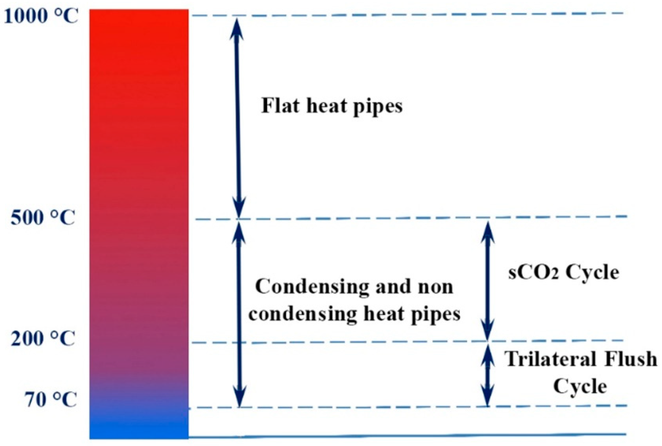
The ideal scientific aim would be to develop technology solutions that address WHR from a wide range of primary flow streams for temperatures of about 70 °C to 1000 °C, and to make the best use of this heat for heating, power generation, or a combination of both. This approach is shown schematically in
Figure 1 (see I-ThERM) [
11].
To this end, one should first accept that WHR solutions can be based on innovative HPs for a wide range of fluid stream types, flow rates, temperatures, and recovered heat uses. The HPs standardization can be motivated by the HPs’ advantages over other conventional WHR technologies, as described above. Standardized plug-and-play solutions or easily customizable solutions for a wide range of applications, including vapor condensation in the exhaust flows, can lead to a maximized WHR potential. The recovered heat can be used either directly, or to drive a power-generation system, or for a combination of these, depending on the nature and needs of specific plants and/or users.
As concerns the H2P conversion, two bottoming-cycle technologies have been developed in I-ThERM, the trilateral flush cycle (TFC) and the sCO
2 Joule–Brayton cycle. Both technologies compete with the state-of-the-art technology in WHR, which is the ORC. Most ORC installations have historically tackled either very large heat sources or very small ones. As a result, there is a gap in the power output range from 100 kW to 1.0 MWe [
30]. In addition, for HT WHR applications using the sCO
2 cycle, the heat rejection can be at an HT sufficient for heating, or even for driving a TFC system, when its capacity properly matches that of the sCO
2 system. The potential for energy and cost savings is closely linked to the heat flow in the plant in most cases. The basic idea behind WHR is to try to obtain the maximum amount of heat in the plant and reuse it as much as possible, rather than just releasing it into the air or into a nearby river.
Summing up, the TFC system for LT (70–200 °C) and the sCO
2 for MT (200–500 °C) and their combination with HP heat-recovery technologies can maximize the potential for power generation from waste heat streams. A detailed description of the “new” technologies described in
Figure 1 is given in the sequel.
2.1. Flat Heat Pipes
Condensing economizers are a proven technology that can provide up to a 10% increase in boiler efficiency, provided that the exhaust is clean, such as that of natural gas burners. For example, radiant HEs for industrial applications have been proposed in the cement industry, but at LT. In this context, the I-ThERM’s HPHE and coatings provide new solutions to industry.
Several studies have been conducted to investigate the HPHEs for WHR, such as [
31,
32,
33,
34]. An experimental investigation of the HPHE in the I&S industry was conducted by Ma et al. [
35]. The authors reported that the water-to-water HPHE was able to recover a heat-transfer rate from 6.37 kW to 7.36 kW or 129.24 W/(m
2K) to 150.67 W/(m
2K), respectively.
Heat pipes (HPs) are among the most popular passive heat-transfer technologies. Important parameters to determine the efficiency of an HP are the choices of the working fluid and casing material [
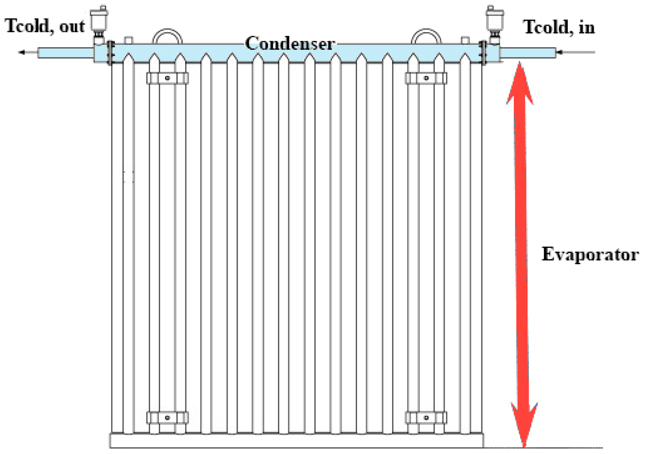
36]. Heat pipes have a broad range of usage, from LT cryogenic applications to HT applications, in which efficient heat transfer is required. Thus, an HP can be used in a variety of applications, such as nuclear and LT applications. Low-temperature applications include industrial sectors such as pharmaceutical, food processing, and biotechnology, as well as chemical and medical industries. Although HP technology is very promising and efficient for many applications in industry, there are still factors to consider, such as cost and technology development. Compared to conventional heat-transfer methods, HPs have a higher initial cost. HPs are in general cylindrical, although the evaporator or condenser can also be flat; in such a case, they are called flat HPs. Compared to conventional cylindrical HPs, FHPs (
Figure 2) have important advantages associated with their isothermal characteristics and flat evaporator surface, which maximizes the radiation absorbing area. FHP WHR systems constitute a new innovation (UK patent application Nos. 1,410,924.3 and 1,410,933.4). Their innovation potential is quite significant, as there are currently no such systems on the market.
Clearly, FHPs have the same benefits as conventional HPs, but due to their geometry, they can be used in specific applications more efficiently. For example, the combination of flat pipes and photovoltaic thermal (PV/T) panels was a successful combination, as stated by Jouhara et al. [
37], as this could reduce the manufacturing costs and increase the viability of mass production. The choice of working fluid and material for the HP can enable FHP systems to absorb or reject heat in a particularly wide range of temperatures, from below 0 °C to above 1000 °C.
Figure 2.
Flat heat pipe application schematic (adapted from [
38]).
Figure 2.
Flat heat pipe application schematic (adapted from [
38]).
Not many studies on FHPs are available in the literature. Jouhara et al. [
38] designed and manufactured an FHP capable of recovering heat by thermal radiation from sources at temperatures higher than that of the surface of the HPs. The overall dimensions of the flat HPHE were 1 m high and 1 m wide. The HPHE consisted of 14 stainless steel pipes connected by a header at the bottom and a tube HE at the top. The prototype was tested in a laboratory conditions, as well as in an industrial steel process. It was concluded that FHPs were promising for WHR in the steel industry, but there were also some challenges needing further investigation. In addition, Jouhara et al. [
39] developed and validated a novel PV/T system, called a “heat mat”, which was based on FHP and operated as a building envelope. The effects of cooling cycles on the temperature and electrical output of the FHP PV/T panels were experimentally examined. It turned out that the temperature of the panels decreased from 40–58 °C to 28–33 °C, while the electrical efficiency increased by 15% with the use of an active cooling cycle in the panels. Moreover, the thermal efficiencies of the heat mat with and without the PV layer were 50% and 64%, respectively.
FHPs can be used for heat recovery from LT and MT sources. FHPs that can be manufactured in different configurations can also be used for first-stage heat recovery from HT exhausts. They can also be used for temperature control of spaces and liquid baths. Flat HPs with the right choice of materials and working fluid can be able to recover heat primarily by radiation, but also by convection at temperatures > 200 °C, and they use this heat for power generation through the sCO2 cycle.
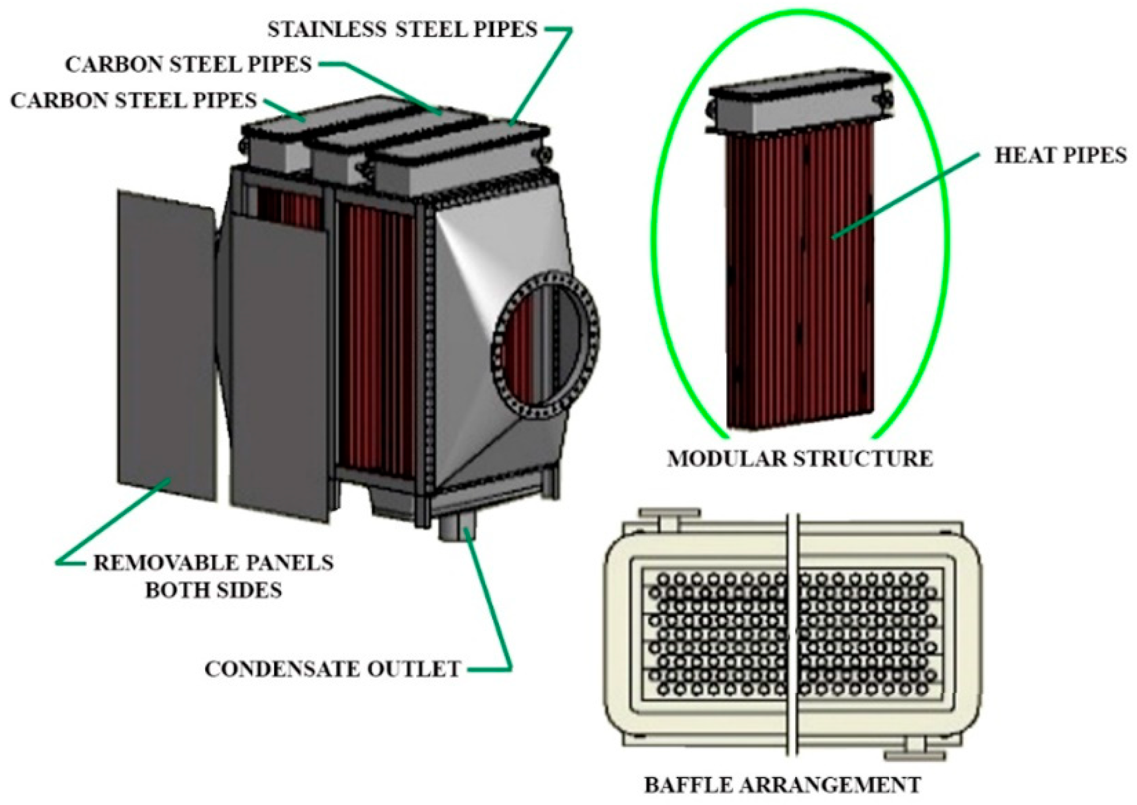
2.2. Heat-Pipe Condensing Economizers
As already mentioned, there are different types of HEs for different applications but with similar functionality, such as finned tubes, coiled tubes, and condensing and noncondensing economizers. The latter two are mainly used to increase the efficiency of boiler systems. Boilers equipped with condensing economizers (CEs) can reach overall efficiencies exceeding 90%. A CE, by reducing the flue gas temperature below its dew point, can cause the overall heat recovery and the steam system efficiency to increase by up to 10%, leading to an improved WHR effectiveness.
Condensing economizers (
Figure 3) provide new WHR prospects due to their very high heat-transfer coefficient, large heat-transfer surface area, and low drop in gas side pressure. There are two types of CEs: those of indirect and those of direct contact. Indirect-contact CEs remove heat from the hot gases by passing them through HEs. Direct-contact CEs offer high heat transfer through water recovery capability, as the heated water can be collected for boiler feed water, space heating, and/or plant process needs. The recovered water is acidic, requiring treatment before use such as membrane technology, external heat exchange, and/or pH control.
The standardized designs based on HPs for WHR from gaseous exhausts have the following capabilities: (a) they allow easy application with minimal process interruption; (b) they require minimum space; (c) they require minimum heat-transfer area due to the two-phase heat-transfer capability of HPs; (d) they allow maximum heat recovery through condensation by an appropriate selection of materials and coatings; and (e) they provide easy cleaning and reliable and minimum maintenance operation.
Similar to FHPs, innovations in this area also include exploring and determining optimal material coatings and HP fluids for different temperature ranges, approaches to improving the primary (exhaust/process) fluid heat-transfer coefficient for the different temperature ranges, and a tool for designing and determining condensing HPs.
There are two ways to recover the waste heat from boiler flue gases. Conventional economizers preheat the boiler make-up or feed water. CEs recover both latent and sensible heat from the flue gas, thereby increasing boiler efficiencies to more than 90%. Heat pipe CEs can be installed in harsh environments, exhibiting high resistance to corrosion and acidic gases. These HPCEs could gain a major advantage over the conventional CEs and gas boilers as optimum material coatings and HP fluids are developed for different approaches to improve the primary (exhaust/process) fluid heat-transfer coefficient for different temperature ranges. Design criteria for CEs coatings can also be found in [
40,
41], in which a comparison between film-wise and drop-wise condensation related to corrosion and an increase in the heat-transfer rate was presented.
Condensing and noncondensing HPs (economizers) can be used to efficiently recover heat from exhausts and use this heat to generate power through the sCO2 cycle at temperatures as low as 200 °C. Below 200 °C, the TFC can be employed (see below). Where liquid waste streams are available at suitable temperatures below 100 °C, standard HEs (plate, shell-and-tube, etc.) can be employed.
2.3. Trilateral Flush Cycle
Regarding H2P systems, ORCs have become a mature technology adopted in industrial environments. ORC units are commercially available at small (0.5–100 kWe) and large scales (1–20 MWe), with economies of scale that reduce the capital costs of the heat to power block from EUR 9000/kWe to EUR 3000/kWe. ORC systems have been adopted mainly in applications with a temperature range between 100 °C and 300 °C. As such, the high-grade waste heat potential that is typical of the I&S, aluminum, glass, and cement industries has not been fully exploited yet. The same applies to LT heat sources that, for instance, characterize the food or paper sectors. Based on the case studies analyzed, I-ThERM’s TFC and sCO2 could provide substantial advantages compared to ORC technology, in terms of efficiency, footprint, power flexibility, and the use of environmentally friendly working fluids.
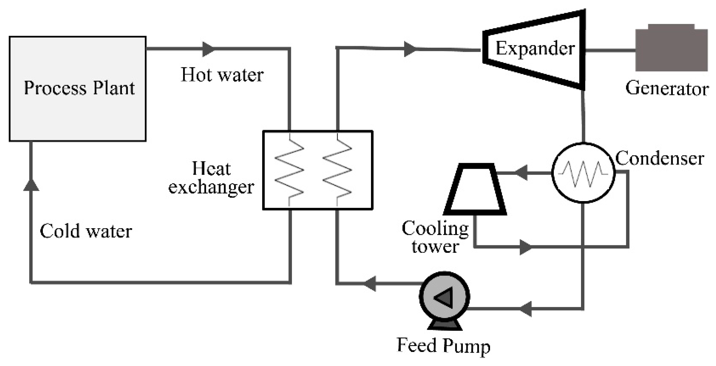
The TFC is a thermodynamic power cycle with its expansion starting from the saturated liquid state rather than from a vapor phase (see
Figure 4). In the absence of a boiling part, heat transfer from the heat source to the working fluid (liquid) is realized due to good temperature matching. Compared to an equivalent steam ORC system, the TFC has a twice as high power-recovery potential [
42]. Moreover, TFC can operate with no need for an extra cooling tower/heat rejection system, where heat in the waste stream is rejected. The TFC has been under consideration for more than 30 years, but the low efficiency of expander technology and the high pump power have hindered its development up to commercialization.
The efficiency of the system also depends on the efficiency of the two-phase expansion process; this has been the main obstacle in the development of the TFC cycle up to the commercialization stage. Another problem is the relatively high pump power, which limits the net electrical power available from the system. Studies and laboratory investigations have shown, however, that adiabatic expansion efficiencies of more than 70% can be achieved [
43,
44].
The proposed TFC systems can be compared to conventional ORC units installed in LT/MT (70–200 °C) industrial processes. An important development beyond the state of the art is the thermally driven compression system, which can replace the pump in the TFC cycle. This can reduce the parasitic losses of the cycle and improve the overall thermal efficiency. Thus, the proposed TFC units can replace the conventional ORC units working with MT gases.
A small-capacity TFC system with 5 kW electrical power output was developed and tested by Spirax Sarco at its Cheltenham, UK, facilities. This system used the thermal energy from the waste stream to provide the pumping energy for the cycle, thus overcoming the disadvantage of the high pumping power of TFCs. This should make the TFC an attractive system for power generation from LT heat sources as low as 70 °C. Optimizing turbine steam expanders, already developed by Spirax Sarco for low-capacity steam power systems to operate efficiently at the necessary heat source LTs system, will increase heat recovery.
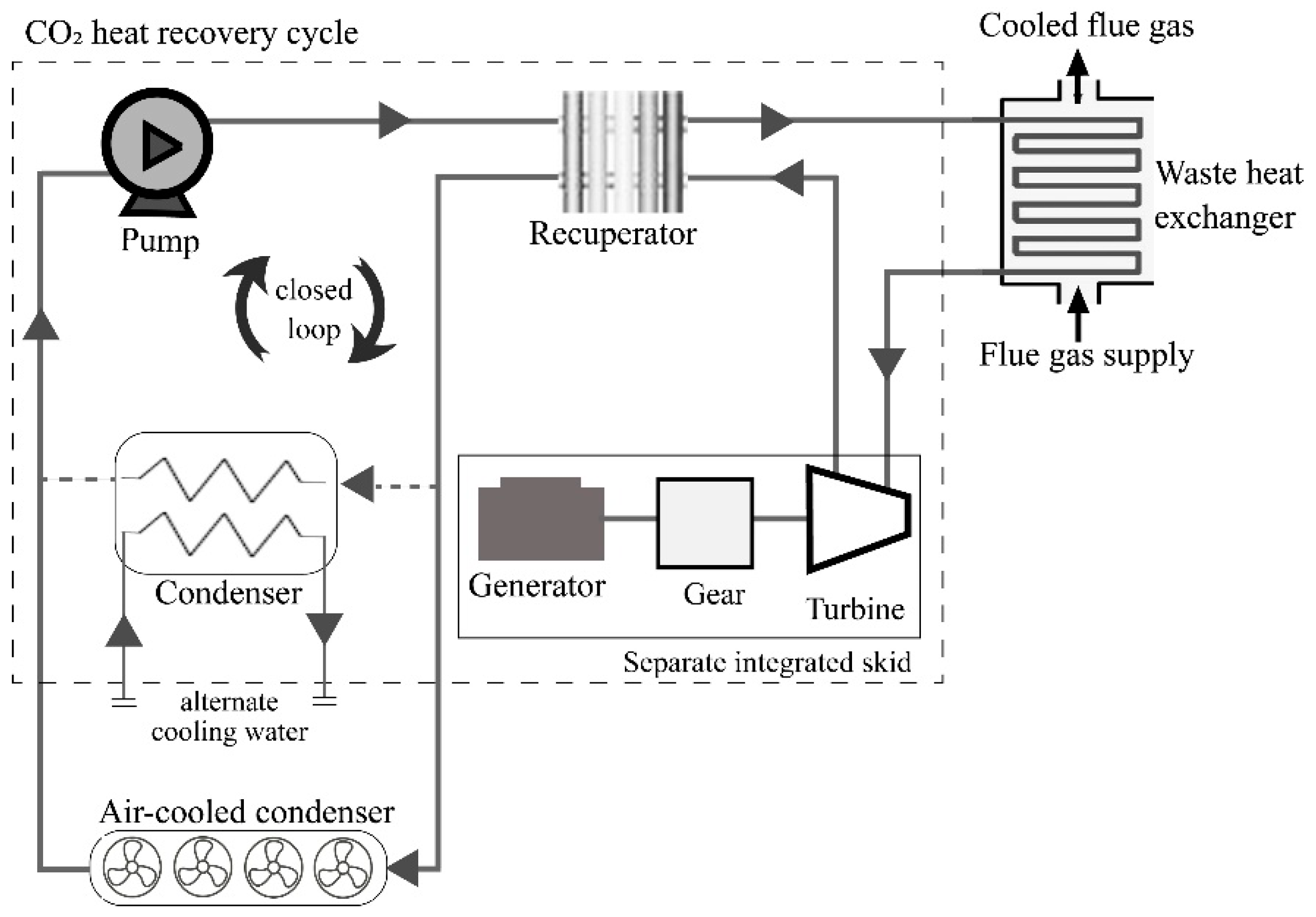
2.4. Supercritical Carbon Dioxide Cycle
In recent years, there has been considerable research and development of ORC systems, and a number of manufacturers are currently researching systems for a range of applications. While the current state of the art shows maturity for the first generation of ORC systems, with typical efficiencies of 6% to 16%, there is still room for further research and development to increase efficiencies to 20% [
29].
A technology that has the potential to provide higher thermal energy conversion efficiency compared to ORC is the supercritical CO
2 Brayton Cycle system (sCO
2), illustrated in
Figure 5.
Supercritical CO
2, operating in a similar manner to other turbine cycles, uses carbon dioxide as working fluid. CO
2, unlike other working fluids, undergoes radical density changes over small temperature and pressure ranges; this allows large amounts of energy to be extracted at HT using relatively small-sized equipment, of a smaller size than steam or gas turbines. It has been demonstrated through modeling and laboratory studies that the sCO
2 cycle can provide, depending on operating pressures and temperatures, an energy-conversion efficiency of 30% [
45].
According to Ahn et al. [
46], the sCO
2 Brayton Cycle has gained much attention for application in next-generation nuclear reactors. The authors reported that this cycle has a great potential to be used for WHR as well.
Supercritical CO2 cycle systems are under research and development by major power system manufacturers such as Mitsubishi Electric, Siemens, etc. A large, 7.5 MWe system, the Echogen EPS100, is under research and development for large industrial fuel-fired processes, utility-scale power generation, and concentrated-solar thermal utility applications.
However, a small modular sCO2 power system could be easily employed for a variety of HT H2P applications. The sCO2 cycle is of a size 10 to 100 times smaller than the Rankine cycle, with its efficiency exceeding 30%, and has a working fluid (CO2) with good properties; CO2 is nonflammable and nontoxic, and has a global warming potential of 1. Similar to TFC systems, sCO2 units can be compared to conventional ORC units installed in HT (200–500 °C) industrial processes.
A 5 kW CO2 cycle system was developed by Enogia (Enogia, Marseille—France) and installed in a specially designed test facility at Brunel University London for further testing and development of a 50 kWe system for power generation using WHR from a biomass boiler.
2.5. Potential Market and Performance of the “New” Technologies
The main industrial sectors for the application of the “new” technology solutions are: (i) most industrial sectors with H2P generation—heat source temperatures of 70–200 °C; (ii) sectors with heat-to-power generation—exhaust temperatures of 200–500 °C, such as cement, ceramics, food and drink, metals, paper and pulp, etc.; and (iii) sectors with temperatures up to 500 °C, such as metal and petrochemical.
In order to assess the potential of the above-mentioned technologies in the EU market, it should be noted that, as already mentioned, the TFC and sCO
2 systems were assessed in the ORC market, and the HPCE systems in the corresponding CE market. These can be found in the literature; for example, [
4,
6,
9,
10].
In terms of FHP technology, the potential market can be assessed by identifying the industrial processes in which FHP could be used. As mentioned above, an FHP system is designed for heat recovery mostly by thermal radiation from sources at temperatures higher than that of the surface of the HPs. The FHP outer surface absorbs the radiation heat and transfers it through the HP evaporator wall by conduction to the inner surface. Once the working fluid attains the saturation temperature, it evaporates and flows upward to the condenser. Then, through a shell-and-tube HE system, the heat is transferred to the cooling fluid, which condenses the working fluid. Finally, the condensate flows back to the evaporator section under gravity. Installation of FHP panels requires industrial processes to have radiant heat sources with temperatures higher than the surface temperature of the HPs, and open spaces near these processes for the installation of FHP panels to recover the radiant heat. There is plentiful industrial manufacturing with HT processes and wasted heat, but using the FHP system requires two basic conditions: (i) the heat must be transferred by thermal radiation; and (ii) the existence of open space near the radiant source for the panels’ installation. The I&S industry turned out to be the best option for using HP systems, owing to the large amount of the radiant waste heat produced during the casting, rolling, and cooling processes in the formation of products. In particular, FHPs could be used in the wire rod process—a very common process in the I&S industry—to recover radiant heat from the cooling/rolling stage from the wire rod mill, where the hot wire rope moves after the casting machine.
A very detailed analysis can be found in [
4]. The expected performance of the above technologies compared to the baseline technologies in relation to potential PBPs is shown in
Table 1.
Summing up, the benefits from such implementations of the “new” technologies are: (i) a reduction in the parasitic losses of the cycle and improvement of the overall thermal efficiency with the TFC system; (ii) the principles of this innovation can also be applied to other power systems such as ORC cycles; (iii) small capacity range, up to 100 kW (sCO2 system); (iv) can absorb/reject heat over a very wide temperature range, from below 0 °C to above 1000 °C (with the use of the FHP systems); (v) can improve the primary (exhaust/process) fluid heat-transfer coefficient in different temperature ranges and increase the quantity of recovered heat (HPCE systems). In addition, regarding space requirements, as mentioned above, the HPs for FHPs and HPCEs can lead to minimization of the relevant heat-transfer area and space. In general, the space requirement matter for the use of certain technologies (including TFC and sCO2, comparable to ORC) is of course dependent on the space characteristics of each application site.
3. Case Studies of WHR Technologies
In this section, a series of case studies related to WHR and applied technologies is given in detail.
Casci et al. [
47] used ORC technology by means of exhaust gases at MT, during the process of ceramic firing in a tile-tunnel kiln, in a ceramic production plant. Thermal oil was used as heat-transfer liquid to transfer the heat to the ORC engine. The overall efficiency attained was in the order of 80%. An economic analysis was performed, yielding minimum and maximum PBPs of 2.86 and 4 years, respectively, for an operational time of 7000 h/year. For an operational time of 8000 h/year, the minimum and maximum PBPs were 2.5 and 3.5 years, respectively. Finally, an 18% IRR (internal rate of return) was also estimated for a life expectancy of 5 years.
Engin and Ari [
48] proposed a WHR steam generator (WHRSG) for the study of heat recovery in a dry-type cement rotary-kiln system. The waste heat from the clinker cooler and the kiln exhaust gas were used as heat streams, with average temperatures of 215 °C and 315 °C, respectively. The streams were fed into the circulating water of the WHRSG unit and steam was produced, which subsequently drove a turbine for the generation of electrical energy. Assuming an implementation cost of USD 750,000, an economic analysis was performed yielding total savings of USD 560,000/year and a PBP of 17 months, based on the finding that up to 8 GWh/year could be saved.
Arzbaecher et al. [
49] studied the Umeå Energi Ltd. power plant, which was combined with a municipal/industrial wood waste burning facility, that was built in Sweden in 2000. The authors reported a heat-recovery system consisting of an integrated 14 MW compression HP that recovered waste condensing heat from the flue gas and transferred it to the district heating system. Moreover, the plant separated the ammonia slip produced by thermal NOx reduction, with ammonia being recovered and recirculated in the boiler for reuse.
The WHR of a textile factory in Bursa was investigated by Pulat et al. [
50]. The authors used a theoretical approach (thermodynamic analysis) and a shell-and-tube heat exchanger with the wastewater stream, and reported an efficiency of 0.92 and a PBP of less than 6 months for the WHR system.
Hita et al. [
51] conducted a study to assess the heat-recovery potential in the food and beverage industry using the TIMES model, which is an energy-perspective model. TIMES can be used for the analysis of either the entire energy sector, or a single sector, such as food and beverage. Heat sources in an LT range of 30–60 °C can be found in various equipment, such as air compressors, chillers, and other thermal end-uses. Such a heat, being at too low a temperature, cannot be recovered by a HE in order to be directly used in industrial processes. The authors suggested that HPs constitute a solution to recover and not waste this LT heat. The price of an HP depends greatly on the working conditions, with standard machines costing (at the time) 1500 EUR/kW and 1800 EUR/kW for temperatures of up to 100 °C and up 140 °C, respectively. Finally, the amount of heat recovered from different processes was calculated by the TIMES model as follows: (i) heat recovered in air compressors = 50% × input energy; (ii) heat recovered in chillers = 70% × (2.5 + 1) × input energy; (iii) heat recovered in thermal end uses = 15% × input energy.
Alvarez et al. [
52] conducted a study at two steel manufacturing factories in Asturias, Spain, using a heat-recuperation process based on a steam Rankine cycle. There were two blast furnaces in the factories, and slag production accounted for almost 80% of the byproducts. Most of the slag was converted to granulated slag, with the rest left to cool down in open air. The authors presented a proposal for WHR for the specific case scenarios. The energy potential calculated by the authors was given at 1300 TJ per year. The inlet temperature to the steam turbine was 453 °C, and the amount of slags was 1.09 Mton per year. The efficiency of the recuperator was selected at 80%, and the calculated IRR was 10.69% with a PBP of 7.7 years. The authors then noted that the recuperator efficiency was uncertain in technical development, and they considered and presented efficiencies between 60–90%. Finally, a CO
2 reduction of 0.04–0.063 ton of CO
2 per ton of steel was estimated, with power production between 5.7–8.7 MW.
Forni et al. [
53] studied ORC application in cement and glass industrial plants. In the cement case, two heat sources were used for the WHR system. The waste heat streams consisted of the kiln gas resulting from the preheating of the raw material, and the clinker cooler, which cooled the final product (clinker) once it exited the kiln. The waste heat was transferred to the ORC module with the use of the thermal oil. The authors estimated a net electricity generation of 36,340 kWh/year, a PBP of 9.2 years, a net present value (NPV) of EUR 1,050,000 for 10 years, and an IRR of 9% for 10 years. In the glass case, WHR was studied during the float-glass production process, in which the waste heat from the exhaust gas from the float-glass furnace was transferred to the ORC with the help of a thermal oil and an HE. The authors, for this application, estimated a net electricity production of 8910 kWh/year, a PBP of 8.2 years, an NPV of EUR 500,000 for 10 years, and an IRR of 11% for 10 years.
The Slite cement plant in Sweden generates electricity using a steam turbine [
54]. The recoverable heat from the process is sent to an existing electricity plant situated at the cement works, which is operated by a third party that generates electricity reusing a steam turbine. A two-step heat recovery boiler system is used to generated steam in the clinker cooler, as well as in the down duct of the kiln. In 2007, the plant took about 30 MW of heat out of the system. The original design was for 9 MW and, after optimization, the supply then was about 6 MW. The investment cost, as estimated in 1999, was EUR 8 × 10
6 for the boiler and steam distribution system, 25% of which was subsidized. However, costs for the reused existing steam turbine that contributed significantly to the economics of the installation were not stated. The annual electricity production was then about 50 GWh, which was equivalent to 25% of the total power needs of the plant.
The Lengfurt plant in Germany was another case study that used an LT ORC process [
54]. Instead of using steam as the motive medium, the process here was principally based on the use of the organic motive medium pentane, which evaporates at considerably lower temperatures than water. This process used basic principles that have been used successfully in refrigeration techniques. It must be mentioned that the ORC process, which is mainly used for the generation of power from geothermal heat sources, was used here in a cement plant for a first time. It has been shown that 1.0 MW (net) electrical power could be generated in the given mode of operation, with an achieved availability of 97% of the operation time of the cement kiln. The waste-heat output of the clinker cooler, via the clinker cooler exhaust air, was 14 MW, while the exhaust gas temperature was between 300–350 °C; approximately an average of 9 MW was extracted. Due to specific operating conditions of the kiln and the kiln grate clinker cooler, it occurred at times that the output of the turbine was lower than originally designed. However, in 2007, the waste-heat power-generating plant covered up to 9% of the electrical power requirements needed for a cement plant, and it has gradually been expected to increase to up to 12%. As a result, CO
2 emissions from combustion related to power generation could be reduced by approximately 3000–7620 ton/yr.
Campana et al. [
55] carried out a study analyzing the potential use of ORC WHR systems in European energy-intensive industries. It was reported that there were 259 cement plants in the EU with an overall capacity of 247.81 million metric tons. Not all 259, but 241 plants were considered in their study, due to various process limitations and lack of information from the rest. As for the steel industry, there were many processes and techniques in production. The ORC application was considered to be more suitable for WHR than the exhaust gas of electric arc furnaces (EAF) and rolling mills. There were more than 190 EAFs in the EU. Three different layouts could be conceived in relation to the HEs, which: (i) are placed just outside the furnace (at 300–1600 °C); (ii) are placed before the quenching tower (at 200–900 °C); or (iii) recover heat from the fluid used in the quenching tower. The inlet gases in the conditioning system have temperatures between 150–350 °C.
Karellas et al. [
56] examined and compared two different WHR methods, namely the waste stream Rankine cycle and an ORC, for a cement plant. The authors estimated an offer of 6 MW electric power for a typical cement plant, and also reported that the water stream-cycle provided a better performance over the ORC, with a system efficiency of 23.88% and 17.56%, respectively. Additionally, a favorable PBP of up to five years was estimated.
Hebenstreit et al. [
57] studied the integration of electrically driven HPs with wood chip and wood pellet boilers. The authors estimated a 2–13% decrease in operating costs, a 3–21% increase in energy efficiency, and a 2–12-year PBP.
Seck et al. [
58] investigated the impact of WHR using HPs in industrial processes by 2020 in the French food and beverage industry. The authors showed that the implementation of HPs in the food and beverage sector led to a final 12% reduction in energy consumption by 2020, as compared to 1990 levels, representing about 8.1 TWh, while the reduction in CO
2 emissions was about 9% (around 2 Mt of emissions).
Peris et al. [
27] used ORC technology in a ceramic industry for low-grade WHR. The recovery facility consisted of a recuperator, an HE, and a heat-transfer loop from the furnace (heat source) to the ORC unit. The gross electric efficiency and the net electric efficiency achieved were 12.47% and 10.94%, respectively. The authors conducted a feasibility study of the application, estimating a 120,886 kWh annual electricity generation, a EUR 138,286 NPV for 15 years, a 22.88% IRR, and a 4.63-year PBP.
Chen et al. [
59] presented a case study on sensible heat recovery and utilization of hot blast stove flue gas. An absorption HP was first run with the use of flue gas, and was then used to preheat the blast furnace gas. The system performance was optimized in relation to the energy-saving rate and the profit rate. It turned out that the system could achieve a 16.5% energy savings and CO
2 reduction.
Ramirez et al. [
29] carried out a performance evaluation of an ORC unit integrated into a WHR system in a steel mill in Italy. Waste heat was recovered from the EAF fumes to produce saturated steam, which was then delivered either to a district heating (DH) network during the heating season, or to the ORC for electricity generation during the rest of the year. The nominal power output of the ORC was 1.8 MW, while its net efficiency for its first weeks of operation was 21.7%.
Lemmens and Lecompte [
60] investigated the economic impact of flue gas heat recovery using ORC. The maximum temperature of the flue gas was 240–250 °C and corresponded to a thermal power of about 2.8 MW. The authors estimated the project’s IRR at 12.6%, which was higher than all discount rate scenarios, thus pointing toward a positive NPV value. A sensitivity analysis showed that the economics of the project could mainly be affected by changes in the price of electricity and the annual load hours of the system.
Lecompte et al. [
61] investigated the integration of an ORC WHR system of a 100 MWe EAF in Belgium. A theoretical investigation was conducted with the flue gas temperature kept over 90 °C, among other assumptions made. The obtained results indicated that with the use of a stream loop (at 70–90 °C), an electric output of 521 kWe was produced, a figure of 30.7% lower compared to the combined heating case. With the use of an oil loop, instead of water, an increased electrical power of 26% and 39% relative to the systems with and without combined heating, respectively, was reported by the authors.
Wang et al. [
25] presented a comparative study between the ORC and Kalina cycles. The authors used two parameters, namely the ratio of the heat above and the heat below the most salient/concave point (R), as well as the temperature of that point, to express the features of waste heat. The efficiency from waste heat (exergy) to power was used as an energy-performance indicator. For waste heat with a maximum supply temperature of 180 °C, it was shown that for straight and concave waste heat with R not less than 0.2, the Kalina cycle was better than the ORC; the opposite result was shown for convex waste heat.
Nemati et al. [
62] conducted a comparative thermodynamic analysis of two WHR cycles, namely ORC and Kalina, for a cogeneration system. The authors concluded that ORC required a much lower optimal pressure value than that of Kalina, thus yielding lower costs for ORC materials and sealing. Moreover, they concluded that the ORC cycle required a higher turbine size than that of the Kalina.
Mukherjee et al. [
63] performed a study in the food-manufacturing sector that used gas-fired ovens, with a focus on baking processes. The authors found that about 33% of the total energy consumed in these ovens was used for the final product, with the remaining energy that was discharged with the exhaust gases at 150–250 °C constituting a WHR prospect. Nonetheless, due to the LT range, fouling, and corrosive materials present in the exhaust streams, heat recovery became technically challenging and costly. It must be noted that gas-to-liquid heat transfer is mainly used in existing low-grade WHR technologies to produce hot water for use in other areas of the manufacturing plant. Proper design for the case studied by the authors could allow up to 50% of available energy to be recovered through the exhaust stack. Consequently, the energy efficiency of the overall process could increase to about 60%, with the food-manufacturing costs reduced by about 33%.
Spirax Sarco [
64] installed a gas-to-water HPHE in Ireland to solve a problem faced by a dairy: the exhaust fired from heavy fuel oil was high in sulfur, and hence unsuitable for use due to surface condensation and corrosion. Three HP gas-to-water units were installed, with a 488 kW recovery, saving EUR 87,000 per annum with a PBP of 19 months.
Amiri Rad and Mohammadi [
65] performed energy and exergy analyses for the Rankine cycle of WHR at a cement factory. They mentioned that the cement industry is one of the largest industries in terms of energy consumption, and the use of ORC systems for WHR has good potential. The authors studied a proposed steam cycle designed to generate power from the waste heat of the chimneys of a cement factory in Sabzevar, Iran. The waste heat of the kiln chimney overheated at 380 °C; the working fluid entered the turbine as steam at a higher temperature. The steam exiting the turbine was cooled by an air condenser due to water scarceness in Sabzevar. The steam cycle was optimized in relation to energy and exergy. The highest total energy and exergy efficiencies of the recovery system were found to be 16% and 39%, respectively, and occurred at the recovery boiler pressure of 1398 kPa.
Ahmed et al. [
66] presented a design methodology for an ORC, based on real data from a cement factory. An ORC, in conjunction with a gas turbine, was examined for the conversion of the gas turbine’s waste heat into electrical power. It was concluded that the effectiveness of the ORC HE using R134a as the working fluid could increase up to 93%.
Zhang et al. [
67] presented a study on the direct power generation by an ORC from waste heat through an emergy analysis. The authors showed that the emergy yield ratio (EYR) and emergy sustainability index (ESI) of the ORC were 197.52 and 3.97, respectively. Although the ESI of the ORC system was less than that of hydro, wind, and geothermal power plants, it was higher than that of fossil-fuel power plants. Using R134a as the working fluid resulted in an emergy proportion of the working fluid of 13.3%, compared to the total input flows in the construction phase.
Jouhara et al. [
68] investigated the WHR from a ceramic kiln with the use of an installed HPHE. The authors performed an investigation experimentally, theoretically, and numerically. The experimental heat recovered, over a period of 27 h, was between 76 and 103 kW, depending on the kiln operation. The theoretical and the numerical results were shown to be in good agreement with the steady-state operation of the system. The overall heat recovered by the HPHE was noted at 876 MWh yearly. The authors also addressed the return of investment of the system with an estimate of 16 months and a savings of 30,000 GBP/year.
Finally, various other indicative case studies found for WHR systems in the EU and elsewhere are summarized in
Table 2.
4. Conclusions
Owing to the considerably large EU energy overall consumption by industries such as chemical and petrochemical; iron and steel; paper, pulp, and print; and nonmetallic Minerals, and more, there exists a substantial percentage of waste-heat potential to explore through WHR technologies applied in the industrial sector.
This paper presented a research work based on WHR technologies applied to the industrial sector. In the first part, the conventional WHR technologies were mentioned, along with their temperature-range classification according to the WHR classifications.
Then, some “new” WHR systems, such as FHP, HPCE, TFC, and sCO2, were presented. These latter systems can absorb/reject heat over a very wide temperature range, from below 0 °C to above 1000 °C. They can also perform better than the conventional systems, and hence have lower emissions. In terms of the cost of the “new” WHR technologies, it was estimated that they have a 25% extra cost compared to “conventional” technologies, but a significantly improved performance due to higher efficiency. Subsequently, the PBP can be shorter, and the return on investment can be better than “conventional” technologies.
Summing up, the benefits from such implementations of the “new” technologies are: (i) a reduction in the parasitic losses of the cycle and improvement of the overall thermal efficiency with the TFC system; (ii) the principles of this innovation can also be applied to other power systems such as ORC cycles; (iii) small capacity range, up to 100 kW (sCO2 system); (iv) can absorb/reject heat over a very wide temperature range, from below 0 °C to above 1000 °C (with the use of the FHP systems); and (v) can improve the primary (exhaust/process) fluid heat-transfer coefficient for different temperature ranges, and increase the quantity of recovered heat (HPCE systems).
This paper also presented an extensive review of case studies related to the adoption and application of WHR technologies. The benefits to industries of WHR processes, which were obvious, can be summarized as follows: (i) fuel savings and reductions in greenhouse gas emissions; (ii) generation of electricity and mechanical work; (iii) selling heat and electricity; (iv) reductions in cooling needs; (v) reductions in capital investment costs; (vi) increases in production; and (vii) conversion of heat into useful forms of energy.
However, the wide adoption of WHR technologies in industry is hampered by specific “barriers” related to both technical and nontechnical issues. Christodoulides et al. [
71] addressed these issues, and suggested ways to overcome such barriers. One way, of course, is the introduction of “new” technologies that do not have many of the disadvantages of conventional technologies, which can create a pathway for a much wider adoption of WHR by industry.


 ,
, 


