Article

A Design Method for the Cogging Torque Minimization of Permanent Magnet Machines with a Segmented Stator Core Based on ANN Surrogate Models

by
Elia Brescia
,
Donatello Costantino
,
Paolo Roberto Massenio
,
Vito Giuseppe Monopoli
,
Francesco Cupertino
and
Giuseppe Leonardo Cascella
*
Department of Electrical Engineering and Information Technology, Politecnico di Bari, 70126 Bari, Italy
*
Author to whom correspondence should be addressed.
Energies 2021, 14(7), 1880; https://doi.org/10.3390/en14071880
Submission received: 13 February 2021 / Revised: 11 March 2021 / Accepted: 25 March 2021 / Published: 29 March 2021

Abstract

:
Permanent magnet machines with segmented stator cores are affected by additional harmonic components of the cogging torque which cannot be minimized by conventional methods adopted for one-piece stator machines. In this study, a novel approach is proposed to minimize the cogging torque of such machines. This approach is based on the design of multiple independent shapes of the tooth tips through a topological optimization. Theoretical studies define a design formula that allows to choose the number of independent shapes to be designed, based on the number of stator core segments. Moreover, a computationally-efficient heuristic approach based on genetic algorithms and artificial neural network-based surrogate models solves the topological optimization and finds the optimal tooth tips shapes. Simulation studies with the finite element method validates the design formula and the effectiveness of the proposed method in suppressing the additional harmonic components. Moreover, a comparison with a conventional heuristic approach based on a genetic algorithm directly coupled to finite element analysis assesses the superiority of the proposed approach. Finally, a sensitivity analysis on assembling and manufacturing tolerances proves the robustness of the proposed design method.

1. Introduction

Permanent magnet machines (PMMs) are mainly manufactured with one-piece stator cores. Among these machines, fractional-slot concentrating winding topologies ensure low cogging torque, low copper losses and high torque density [1,2,3]. Recently, segmented stator core (SSC) structures have attracted increasing interest since, compared to one-piece stator machines, they allow an easier manufacturing process and reduced material wastage, especially when large machines are considered such as wind and tidal power generators [4,5,6,7,8,9]. However, a SSC structure introduces additional harmonic components (AHCs) of the cogging torque due to the presence of additional airgaps in the flux-path. The cogging torque is an undesired torque pulsation which degrades the PMMs performances because of the induced speed pulsations, mechanical vibrations, and acoustic noise, especially at low speed and inertia [10,11,12,13].
The cogging torque of PMMs with a one-piece stator core can be suppressed by using rotor skewing techniques [10], “dummy” stator slots or notches [14,15,16], different slot openings [17], or by choosing different stator slots and teeth widths pairing [18,19]. While rotor skewing approaches are ineffective in case of SSC machines due to the additional lower order harmonics introduced by stator core segmentations and stator asymmetries [10,11,12,13,20,21,22], the effectiveness of the other techniques has not been proved in the presence of SSCs.
The recent literature provides few design solutions for the mitigation of the AHCs in SSC machines. In [11], the cogging torque of PMMs with SSCs is related to the number of uniform segments, to the combination of different non-uniform segments, and to the different shape of the connecting tongue. In case of uniform stator core segments, the AHCs are minimized when the segments number maximizes the least common multiple (LCM) between the number of poles and the number of segments. Instead, in case of non-uniform stator core segments, the AHCs are minimized if the distance between the additional airgaps is 90° and 120° or 240° electrical degrees when two or three non-uniform stator core segments are considered, respectively. Finally, it is shown how the shapes of the connecting tongues have a negligible impact on the AHCs. However, even when the optimal number of segments and the optimal distance between the additional airgaps is adopted, a non-negligible cogging torque remains. In [8], a semi-analytical method based on the slot openings’ shifting is proposed for the mitigation of the AHCs, providing 85% cogging torque reduction. However, such method is limited only to stator core segments with two slots, and, for some specific topologies it shows a limited effectiveness. Moreover, in some cases, the optimal shift angle can exceed the maximum available shift range. In [23], the cogging torque of an annular PMM (APMM) with a SSC has been minimized by designing multiple, periodically reproduced, independent shapes of the tooth tips. The optimal shapes have been achieved through a topological optimization (TO) solved with a genetic algorithm (GA) coupled with 2-D finite element analysis (FEA). Despite its good results, such as cogging torque reduction of 94%, torque ripple reduction of 70.2%, and negligible influence on the other machine performances such as average torque and back-EMF THD; this technique requires long computational sessions, i.e., about 24 h.
The aim of this paper is to fill the existing gap in the literature, improving the method proposed in [23]. A novel design formula for the choice of the independent tooth tip shapes’ numbers is proposed for the design variables reduction. The computational effort of the TO is mitigated through feed-forward (FF) artificial neural network (ANN) surrogate models. ANN-based surrogate models constitute a promising approach recently investigated for the reduction of computational requirements in electrical machines’ optimizations. This approach allows to couple optimization algorithms with computationally efficient models, avoiding time-consuming FEA iterations, whose computational times are in the order of minutes. In [24], a topological binary particle swarm optimization (BPSO) coupled to a surrogate model based on a convolutional neural network (CNN) together with full and reduced order FEA maximized the torque of a Synchronous reluctance motor (SynRM). By performing 80% of the BPSO iterations using the CNN, results comparable to a full order FEA optimization are achieved. The computational times are reduced of almost 20 times, providing a solution in 24 h. In [25], a multi-objective GA has been successfully used with two Bayesian regularization backpropagation neural networks which approximate the relationship between three design variables and the average torque and the torque ripple of a SynRM. The objective function is computed by means of multiple magnetostatic 2-D FEA, and no comparison with the standard FEA-based approach is provided. Moreover, in [25], a single training instance is performed after the data acquisition while the achieved solution is affected by the approximation error of the employed surrogate model.
Alternatively, in this paper, FF ANNs are trained by means of multiple steps transient-with-motion (TWM) FEA to approximate the relationship between multiple binary design variables, one real design variable, and the cogging torque waveform. The proposed approach is not limited to stator segments with only two stator slots as in [8], but it handles arbitrary topologies with uniform stator segments. Furthermore, the surrogate models are iteratively trained and refined during the heuristic process by means of FEA evaluations of the partial solutions. Finally, the optimal solution is chosen among the FEA data samples and is not affected by the surrogate models’ approximation error as in [25].
Compared to [23], novelties and improvements of this work can be summarized as follows:
  • A more efficient heuristic approach that combines ANN-based surrogate models and FEA;
  • An improved design formula which allows to reduce the number of design variables;
  • A more detailed theoretical study supports the proposed method;
  • The proposed method is validated through an extended analysis to three different segmented stator cores.
The paper is organized as follows: Section 2 presents and analyzes the case study, the novel design formula and the proposed TO is presented in Section 3, in Section 4 the proposed heuristic approach based on the use of ANN-based surrogate models is described, the results are reported in Section 5 and concluding remarks are drawn in the last section.

2. Annular Permanent Magnet Machine with a Segmented Stator Core

For the validation of the proposed method, we choose as a case study an APMM for low power urban wind applications with a large diameter and high number of poles. The main design aspects are reported in [26], where the authors tackled the design of electric generators fully embedded in a ducted horizontal axis wind turbine (DHAWT). Figure 1 shows a sketch of the APMM integrated within the DHAWT. The stator of the APMM is integrated within the diffuser of the DHAWT, while the rotor is constituted by a ring directly connected to the blade tips. This solution avoids gearboxes, increasing the global reliability and efficiency while reducing maintenance costs. Moreover, the diffuser improves the fluid dynamic performances of the wind generator increasing the power capability [26,27]. Similar topologies are also adopted in tidal turbines [9]. Due to the significant size of the machine, a modular structure simplifies the manufacturing and assembling process. Moreover, in [26], the use of printed circuit boards for the stator windings is proposed. This technology allows to reduce production costs as well as the additional copper losses induced by phenomena related to the high electrical frequency operation, such as the proximity effect. The optimization procedure aimed at minimizing the permanent magnets and copper volumes of the APMM is also reported in [26], while the control scheme of the considered APMM integrated in the DHAWT is detailed in [27]. Figure 2 depicts one of the ten modules of the considered APMM with 20, 30 and 60 uniform stator core segments. Machine parameters and materials are summarized in Table 1. Note that the airgap length is fixed according to mechanical constraint related to the DHAWT.
Following the formulation suggested in [23], the cogging torque of an PMM with an SSC can expressed as:
T c o g ϑ r = T N H C ϑ r + T A H C ϑ r ,
where ϑ r is the rotor angular position, T N H C represents the native harmonic components (NHCs) caused by the stator slots, and T A H C is the AHCs caused by the stator segments. The NHCs frequency is an integer multiple of the LCM between the number of poles ( 2 p ) and the number of stator slots ( N s ) [23]. Instead, the AHCs frequency is an integer multiple of the LCM between 2 p and the number of stator core segments ( m ):
T N H C = i T N H C i s i n L C M 2 p , N s i ϑ r + φ N H C i ,       i
T A H C = i T A H C i s i n L C M 2 p , m i ϑ r + φ A H C i ,     i
where T N H C i , T A H C i , and φ N H C i , φ A H C i are the amplitudes and the phase shift of the i-th harmonic component, respectively.
Considering (3), the following harmonic orders of the AHCs are expected in an electrical period for the APMMs with 20, 30 and 60 stator segments, respectively:
L C M 2 p ,   m p = L C M 100 ,   20 50 i = 2 i ,       i
L C M 2 p ,   m p = L C M 100 ,   30 50 i = 6 i ,       i
L C M 2 p ,   m p = L C M 100 ,   60 50 i = 6 i ,       i
For the APMM with 20 stator segments, a higher amplitude of the first AHC is expected with respect to the others APMMs. In fact, in Equation (4), since L C M 100 ,   20 = 100 , the first AHC is produced by the fundamental component of the rotor magneto-motive force (MMF). In (5) and (6), the first AHC is produced by the third harmonic component of the MMF which has a smaller amplitude if compared with the fundamental component. Moreover, the APMM with 60 stator segments is expected to have larger AHCs than the one with 30 stator segments. In fact, when additional airgaps are introduced, the reluctance of the back-iron increases. This introduces more flux linkage across slot openings and tooth tips, increasing the tangential flux density, which adversely affects the cogging torque [11]. Considering (2), instead, the following harmonic orders of the NHCs are expected for the three APMMs:
L C M 2 p ,   N s p = L C M 100 ,   120 50 i = 12 i ,       i
In Equation (7), since L C M 100 ,   120 = 600 , the first NHC is produced by the 6th component of the rotor MMF. Hence, the amplitudes of the NHCs are negligible if compared to the amplitudes of the AHCs.
To analyze the cogging torque of the APMMs, TWM 2D FEA have been performed using the MagNet software. The TWM solver provides accurate solutions by considering the motion effect as well as the induced eddy currents. A 450 steps TWM FEA has been performed to analyze the cogging torque over an electric period. In Figure 3 the cogging torque waveforms and harmonic spectra of the APMMs with 20, 30 and 60 stator core segments are reported. The harmonic spectrum of the APMM with 20 stator core segments has a wide 2nd harmonic and a 4th and 6th harmonics with amplitudes of 0.165 and 0.069 Nm, respectively. The APMMs with 30 and 60 stator core segments have similar spectra in which the dominant cogging torque harmonic is the 6th. The peak-to-peak values of the cogging torque are 9.125, 0.226 and 0.298 Nm, i.e., 76.0%, 1.9% and 2.5% of the rated torque, respectively. In all the cases, the NHCs are negligible if compared to the AHCs. Finally, note that in the last two harmonic spectra, unexpected weak harmonic components occur. These harmonics can be caused by slightly asymmetries in the model [21]. Nevertheless, the obtained results are overall in good agreement with the expectations.

3. Tooth Tips Design

3.1. Theoretical Study and Design Formula

The method proposed for the suppression of the AHCs is based on the design of multiple, periodically reproduced, independent shapes of the tooth tips of the machine, called independent tooth tips. In [23], a simple design formula was developed to determine the number of the independent shapes. This formula has been derived by expressing the airgap flux density as the product of the rotor MMF and a flux-path permeance function. Three separate permeance functions took into account the stator slotting effects of both the modified tooth-tip shapes and the segmented stator core. Therefore, the approach proposed in [23] aims at reciprocally suppress the harmonics of the permeance functions associated to the tooth tips shape and to the segmented stator core with a proper design of the tooth tips. According to this strategy, the developed design formula provides the number of independent tooth tips as the ratio between the number of stator slots and stator segments.
In this paper, a novel strategy to reduce to the number of the independent tooth tips is proposed. Therefore, the number of design variables is reduced, providing a less complex optimization problem. Considering the modified shapes of the tooth tips, the cogging torque of the APMM can be expressed as:
T c o g ϑ r = T N H C ϑ r + T A H C ϑ r + T I H C ϑ r ,
where T I H C describes the components of the cogging torque caused by the shape of the tooth tips, called introduced harmonic components (IHCs). The novel strategy aims at directly suppress the AHCs by means of the IHCs. For this purpose, the IHCs should have the same frequency of the AHCs. To find a relationship between the frequency of the IHCs and the number of the independent tooth tips, we conduct a theoretical study. In [9], the superposition principle is employed to study the cogging torque of PMMs with a SSC. According to this principle, the contributions of the slotted stator structure and of the stator segmentations are independent and can be added together. In particular, the cogging torque contribution due to the slotted stator structure can be studied by considering a non-segmented slotted machine. Commonly made assumptions to study the cogging torque of these machines are as follows [9,19,28,29]:
  • The magnetic energy is stored only in the airgap and PMs volume;
  • The PMs and air permeability are equal to the vacuum permeability;
  • The permeability of the iron is assumed to be infinite;
  • The airgap flux density is constant along the radial direction.
The cogging torque of a rotating PMM can be studied with the well-known energy method, which defines the cogging torque as:
T c o g ϑ r = W ϑ r ,
where W is the stored magnetic energy. According to the above assumptions, W can be expressed as in [19]:
W = 1 2 μ 0 V g   B 2 d V ,
where V g is the volume of airgap and PMs, μ 0 is the vacuum permeability, and B is the no-load airgap flux density expressed as:
B α , ϑ r = Λ α   F m α , ϑ r ,
where Λ is the airgap permeance function, F m is the rotor MMF, and α is the angular displacement along stator circumference. Considering Equation (11), Equation (10) can be expressed as:
W = 1 2 μ 0 V g   Λ 2 α F m 2 α , ϑ r d V = 1 2 μ 0 0 L s t k R 1 R 2 0 2 π Λ 2 α F m 2 α , ϑ r d α d r d z = L s t k 2 μ 0 R 2 2 R 1 2 2 0 2 π Λ 2 α F m 2 α , ϑ r d α ,
where L s t k , R 1 and R 2 are the stack length, the outer radius of rotor, and inner radius of the stator, respectively. Following the approach adopted in [30,31], Λ can be expressed as:
Λ α = μ 0 g α ,
with:
g α = g + l s s α + l t t s α ,
where g is the difference between R 2 and R 1 , l s s is the additional length of the airgap flux-path due to the presence of the stator slots and l t t s is the additional length of the airgap flux-path due to the modified shape of the tooth tips. Assuming l s s α , l t t s α g , (14) can be approximated by the first-order Taylor’s expansion:
Λ α μ 0 g μ 0 g 2 g α g = μ 0 g μ 0 g 2 l s s α + l t t s α = μ 0 g + Λ s s α + Λ t t s α ,  
where Λ s s and Λ t t s are the permeance functions associated to the stator slotting effect and to the modified shape of the tooth tips, respectively. Considering (15), (12) can be expressed as:
W = L s t k 2 μ 0 R 2 2 R 1 2 2 0 2 π μ 0 g + Λ s s α + Λ t t s α 2 F m 2 α , ϑ r d α = L s t k 2 μ 0 R 2 2 R 1 2 2 0 2 π μ 0 2 g 2 + Λ s s α + Λ t t s α F m 2 α , ϑ r d α ,
where Λ s s = 2 Λ s s μ 0 / g + Λ s s 2 , Λ t t s = 2 Λ t t s μ 0 / g + Λ t t s 2 + 2 Λ s s Λ t t s . Compared to the basic machine, the one with the modified shape of the tooth tips has an additional component of the squared permeance function, i.e., Λ t t s . Therefore, the IHCs are caused by the interaction between this component and the rotor MMF:
T I H C ϑ r = L s t k 2 μ 0 R 2 2 R 1 2 2 ϑ r 0 2 π Λ t t s α F m 2 α , ϑ r d α .
If N i independent shapes of the tooth tips are periodically reproduced for all the tooth tips of the machine, the frequency f t t s of the function l t t s α is:
f t t s = N s 2 π N i .
This frequency coincide with the frequency of Λ t t s α . This can be easily verified by means of the Werner formula, considering Equation (15), the definition of Λ t t s , and that the frequency of Λ s s is equal to N s / 2 π , i.e., an integer multiple of f t t s . Considering the orthogonality property of trigonometric functions, in (17) only the harmonic components of Λ t t s α and F m 2 α , ϑ r with the same frequency contribute to the energy, and, thus, to the cogging torque. Therefore, the frequency of T I H C is expressed by:
f I H C = L C M 2 p , N s N i i 2 π ,         i .
Finally, the following expression for the T I H C holds true:
T I H C ϑ r = i T I H C i s i n L C M 2 p , N s N i i ϑ r + φ I H C i ,
where T I H C i and φ I H C i are the amplitude and the phase shift of the i-th harmonic component, respectively.
Equations (19) and (20) are a key result of the presented analytical study. These formulas state that the frequencies of the IHCs of a PMM designed with N i independent tooth tips are multiple of the LCM between the number of poles and the ratio of the number of slots and the number of independent tooth tips. Considering (3) and (20), to obtain IHCs with the same frequency of the AHCs, the following equation should be satisfied:
L C M 2 p , N s N i = L C M 2 p , m .
Therefore, the minimum number of independent tooth tips to suppress the AHCs is the following:
N i = m i n n |   L C M 2 p , N s n = L C M 2 p , m .
Equation (22) is the design formula that allows the designer to choose the number of independent tooth tips. By applying (22) to the APMMs with 20, 30 and 60 stator core segments, the values of N i obtained are 6, 2, and 2, respectively. Instead, by applying the design formula of [23], the values of N i obtained are 6, 3 and 2. Therefore, in this case, the developed design formula allows to reduce the number of independent tooth tips when the APMM with 30 stator core segments are considered.

3.2. Tooth Tips Shape Design through Topolgical Optimization (TO)

Equation (22) ensures that the IHCs include components with the same frequency of the AHCs. However, to suppress the AHCs, it is still necessary to properly set the amplitude and the phase shift of the IHCs through the design of the shape of the independent tooth tips. To face this issue, an effective approach proposed in [
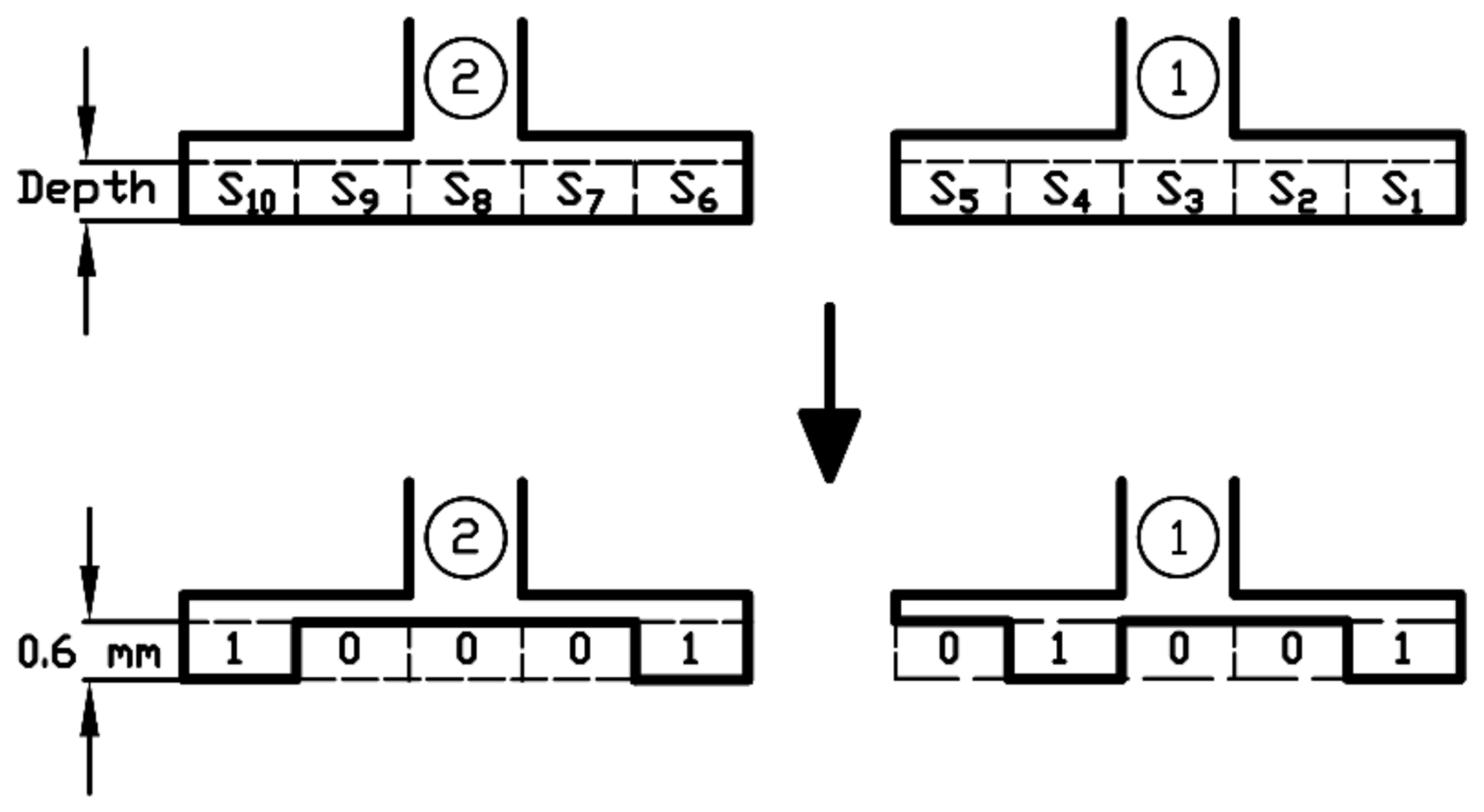
23] is based on the definition of a TO problem. Each independent tooth tip is discretized with a variable depth layer of N s u b sub-regions, called sub-teeth. To define the sub-region materials, a binary variable ( S i j ) is assigned to each ith sub-tooth of the jth independent tooth tip. S i j = 0 denotes air while 1 denotes iron. Moreover, considering the depth of the sub-teeth layer as an additional variable, the design variables of the TO problem can be expressed as follows:
x = S 1 , 1     S N s u b , 1   S N s u b , N i     D e p t h ,
where S i , j 0 , 1 , with i = 1 , ,   N s u b ,   j = 1 , ,   N i , and D e p t h 0   d M A X , with d M A X as the depth limit for the sub-teeth layers. Therefore, N s u b · N i 
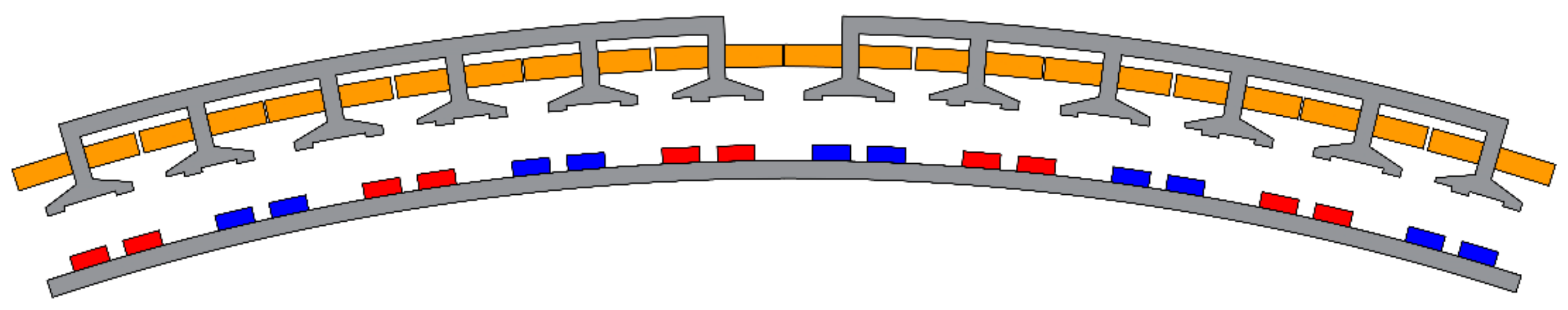
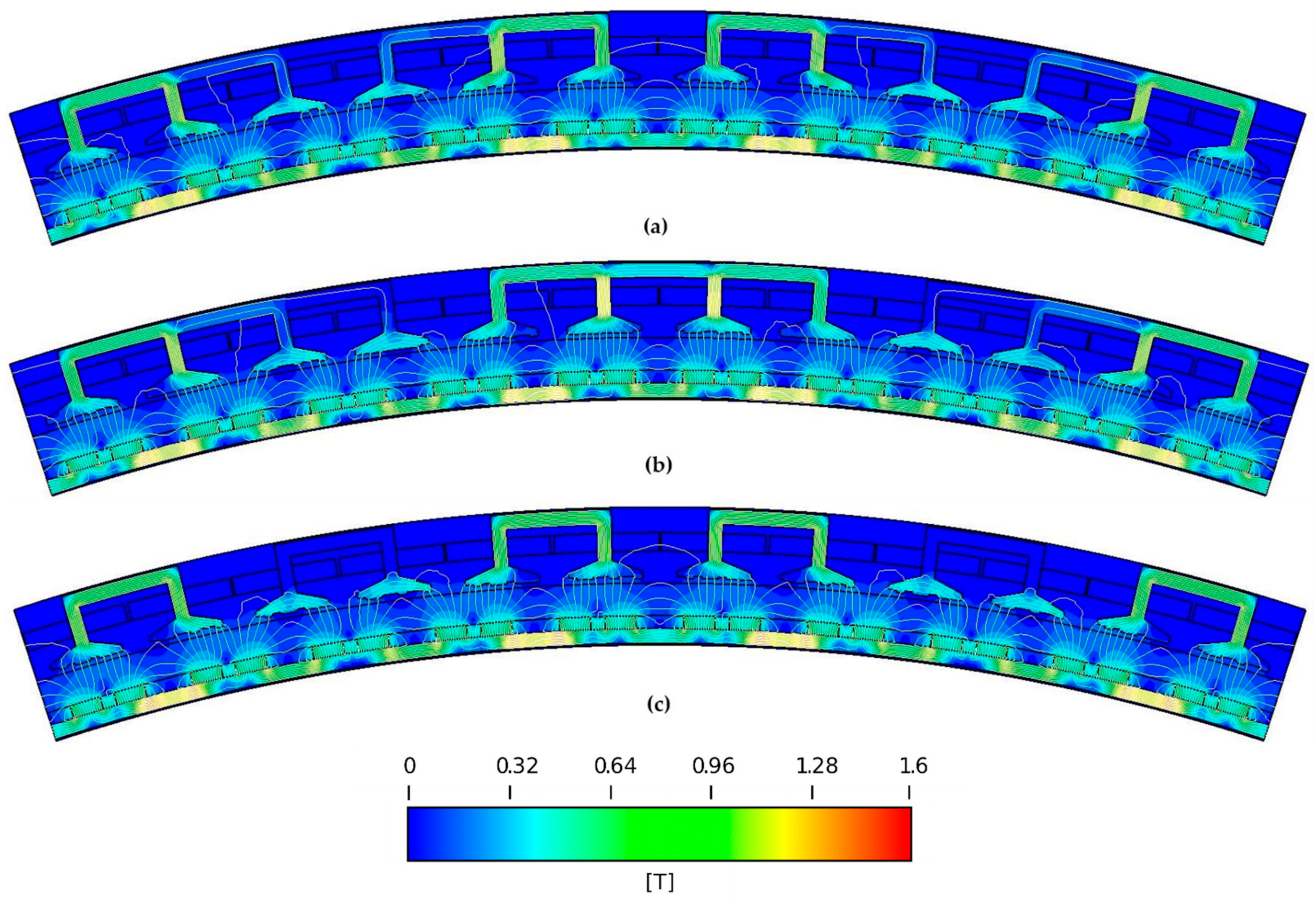
binary design variables and a real bounded design variable are defined. Two independent tooth tips discretized with layers of 5 sub-teeth are shown in Figure 4, while an APMM module designed with the above independent tooth tips is depicted in Figure 5. As shown in the figure, the shapes of the independent tooth tips are periodically reproduced for all the tooth tips of the APMM. The objective function, f T O x , of the TO is defined as the peak-to-peak value of the cogging torque:
f T O x = max T c o g x , ϑ r min T c o g x , ϑ r ,
where T c o g x , ϑ r is the cogging torque waveform of the APMM designed in agreement with the current values of the design variables x . The maximum value of N s u b is limited by the tooth tips width and the manufacturing tolerances, while the maximum value for d M A X is limited by the tooth tip height. The choice of N s u b should be a trade-off between the achievable performances and the computational effort. In fact, the number of the sub-teeth is related to the quantity of the design variables affecting the complexity of the optimization problem and consequently the computational effort required by the heuristic solution. Similar considerations are done about the choice of d M A X .

4. Heuristic Solution Based on GA and ANN Surrogate Models

In [23], a GA directly coupled to TWM FEA has been proposed to solve the TO problem defined by (23) and (24). In particular, the TWM FEA has been used to compute the T c o g x , ϑ r waveform while the objective function has been computed through (24). Even if this approach is effective, it is time consuming since each TWM FEA requires minutes to be performed. In this work, in order to reduce the amount of computational time required to solve the TO, the use of surrogate models is proposed for the computation of the T c o g x , ϑ r waveform.
Figure 6 describes the proposed heuristic procedure. It begins with the choice of the main design parameters: N i , N s u b and d M A X . Then, N s t a r t sample data sets are generated through the TWM FEA of the APMM considering random samples of the design variables in the design space. The sample data consists of a set of inputs X constituting the actual values of the design variables x and a set of outputs Y constituting the values of T c o g _ F E A x , ϑ r computed by the TWM FEA. Specifically, T c o g _ F E A x , ϑ r is a vector of N s t e p + 1 values of the torque in an electrical period, where N s t e p is the number of steps of the TWM FEA. Then, by making use of the sample data, a multi-training phase is performed. Five FF ANNs are chosen as surrogate models. Details about the choice of the FF ANNs will be presented subsequently.
These FF ANNs are employed by the GA for the objective function evaluation:
f T O x = max T c o g _ A N N x , ϑ r min T c o g _ A N N x , ϑ r ,
where T c o g _ A N N x , ϑ r is a vector of N s t e p + 1 values of the torque in an electrical period, computed by the FF ANN. The best three solutions of each trial of the GA are used to perform a TWM FEA and compute T c o g _ F E A x , ϑ r . Thus, the new couples ( x , T c o g _ F E A x , ϑ r ) are introduced as additional data for the next heuristic iteration. The process stops when N M A X sample data are obtained. The achieved solution ( x o p t ) is selected as the best sample among the input data set, i.e., the minimizer of the following function:
f T O _ F E A x = max T c o g _ F E A x , ϑ r min T c o g _ F E A x , ϑ r ,     x X .
The main idea is to implement a step-by-step incremental accuracy of the surrogate models in the proximity of the minimum of f T O x . The authors suggest employing five FF ANNs to mitigate the randomness of the data sample splitting in training and validation data, which affects the surrogate models’ accuracy near the solution of the TO. The best three solutions of each GA are chosen for the next step to cope with the estimation errors of the surrogate models. The main steps of the proposed procedure are detailed in the following subsections.

4.1. Computationally-Efficient TWM FEA

Each one of the 450 steps TWM FEA performed to obtain the cogging torque waveform requires about 55 min on a HP Z440 workstation. Since the proposed procedure requires hundreds of TWM FEA, the authors suggest moderating the number of steps of the TWM FEA according to process time. To ensure that the TWM FEA catches the dominant cogging torque harmonics to minimize, the number of steps should be greater than the double of the maximum harmonic order of the cogging torque harmonics to be minimized, according to the Nyquist criterion. Considering that the maximum order of the cogging torque harmonics of the analyzed APMMs is 6, 36 steps has been chosen for the TWM FEA performed during the proposed heuristic procedure. Therefore, T c o g _ F E A x , ϑ r consists of 37 values of the torque in an electrical period. Note that 36 steps ensure an acceptable accuracy as will be shown later.

4.2. FF ANNs Surrogate Models Design

The designed FF ANN is depicted in Figure 7. The inputs and outputs are the design variables x and the T c o g _ A N N x , ϑ r waveform, respectively. The architecture consists of an input layer of N s u b N i + 1 neurons, of N H L hidden layers, each one with N H N neurons, and an output layer of 37 linear neurons. The hidden neurons’ activating function is the hyperbolic tangent sigmoid (tansig).
To obtain the five FF ANNs employed by the GA for the objective function evaluation, the following training procedure is proposed. First, the N s a m p l e sample data are randomly split in training (80%) and validation (20%) data. Then, the number of hidden layers and the number of neurons for each hidden layer are chosen among the following sets of values:
N H L 1 ,   2 N H N 2 ,   4 ,   6 ,   8 .
The Levenberg-Marquardt algorithm, i.e., one of the fastest among ANNs training methods [32], is applied to the training data set to determine the weights and biases of the FF ANN. Moreover, to avoid the ANN over fitting on the training data, a stop criterion based on the maximum validation failures is adopted. This criterion stops the Levenberg-Marquardt training algorithm if the estimation error on the validation data (generalization error) fails to improve for ten epochs in a row. This step is repeated for all the possible combinations of N H L and N H N , hence, 8 FF ANNs are trained according to (27). Finally, the trained FF ANN with the lowest validation error is chosen as surrogate model. Preliminary analysis have shown that, compared to Equation (27), higher numbers of neurons and hidden layers don’t ensure better validation errors considering a number of data samples lower than 300. As shown in Figure 6, this training procedure is repeated five times to obtain five ANN-based surrogate models. Note that the five FF ANNs could have different structures, i.e., different values of N H L and N H N . Moreover, these structures could vary with each iteration of the heuristic procedure. In fact, it is expected that the optimal number of hidden layers and neurons increases when the number of sample data increases.

4.3. GA Design

The main parameters and settings of the designed GA are summarized in Table 2. As the computation of the objective function using the surrogate models is very fast, the GA can operate with large individuals and generations to increase its performances. In this work, the initial population is made by the best 50 samples of the input data set X , and 350 samples obtained through a uniform sampling in the design space.

5. Results

5.1. Results of the Proposed Heuristic Procedure

The design parameters used to perform the proposed heuristic procedure are reported in Table 3. According to (22), N i is 6, 2 and 2, respectively. Moreover, we set N M A X = 265 in order to perform the proposed optimization in about 24 h, as can be deduced by Table 4, where the computational times of the main steps of the proposed heuristic procedure are reported. The training phase is related to the five FF ANNs surrogate models. Table 5 shows the results of the proposed heuristic procedure obtained on the APMMs with 20, 30 and 60 stator segments. Since the proposed method includes stochastic processes, i.e., the surrogate models training phase and the GA heuristics, it has been applied five times to properly evaluate its performances. As it can be seen, the method ensures outstanding performances: in all the cases a reduction of the cogging torque higher than 85% is achieved. Particularly noteworthy are the results achieved on the APMM with 20 stator segments. In fact, in this case, a cogging torque lower than that of the basic APMMs with 30 and 60 stator segments has been achieved.
Figure 8 shows the cogging torque peak-to-peak values computed using the TWM FEA during the best optimizations, i.e., optimization no. 1, 2 and 2 for the APMMs with 20, 30 and 60 stator segments, respectively. As it can be seen, a reduction of the cogging torque is already achieved with the first GA solutions, then, as the number of data samples increases, the accuracy of the surrogate models improves and better solutions are achieved by the GA heuristics. Moreover, in the case of APMMs with 30 and 60 stator segments, the best solutions are achieved from the early iterations. In fact, in these two cases, fewer design variables are used. Consequently, the FF ANNs surrogate models ensure good approximation performances of the objective function even with few data samples. This stresses the importance of reducing the design variables through a proper choice of the number of independent tooth tips to save computational time.
Figure 9 shows the cogging torque waveforms and harmonic spectra obtained with 36 and 450 steps TWM FEA of the best APMMs achieved by the optimizations. The peak-to-peak values of cogging torque computed with the 450 steps TWM FEA are 0.224, 0.042 and 0.0362 Nm for the optimized APMMs with 20, 30 and 60 stator segments, respectively. Therefore, a good agreement between the 36 and 450 steps TWM FEA is verified. Note that in all the cases a remarkable reduction of the dominant AHC is achieved. Moreover, the optimized APMM with two stator segments also shows an improvement of the 4th and 6th harmonics over 50%. These results demonstrate the effectiveness of the proposed method in the minimization of the AHCs of the cogging torque. The no-load flux density distribution of the best APMMs achieved by the optimizations are shown in Figure 10. This figure also shows the optimized shapes of the tooth tips, while the solutions achieved ( x o p t ) have been reported in the figure caption. A low value of the flux density can be noted. This corresponds to a design choice of the APMM selected as a case study. In fact, this choice allows to reduce the iron losses while meeting the torque requirements without increasing the copper losses, i.e., the main source of the losses of the considered machine.
To fully demonstrate the validity of the design Formula (22), an analysis of the results achieved with values of N i in disagreement with the design formula is required. Figure 11 shows the results achieved through the optimizations on the APMM with 20 stator segments with N i = 3 ,   4 , in disagreement with Equation (22). As expected, a weak reduction of the cogging torque is achieved. Figure 12 shows the cogging torque waveforms and harmonic spectra of the best achieved solutions, obtained with a 450 steps TWM FEA. The cogging torque peak-to-peak values of the optimized machines are 6.927 and 6.805 Nm respectively. Note that the APMMs with N i = 3 has an higher 4th harmonic compared to the basic one (greater by 42.8%) while there is a weak influence on the 2nd (lower by 24.7%) and 6th (lower by 17.7%) harmonic. Moreover, the APMM with N i = 4 has an higher 6th harmonic compared to the basic one (greater by 55.9%) while there is a weak influence on the 2nd (lower by 18.8%) and 4th harmonic (lower by 3.7%). These results agree with the theoretical study since in an electrical period, from (20), the harmonic orders of the IHCs expected for N i = 3 ,   4 are 6 i and 4 i , respectively, with i . These results demonstrate the validity of the developed design formula (22). Note that the solution x of the TO might be also constituted by the same shape for all the stator tooth tips. This implies that the design of a single tooth tip shape does not affect the AHCs of the cogging torque. Consequently, traditional methods based on dummy slots or notches equally placed in all the tooth tips cannot be adopted for the minimization of the AHCs.

5.2. Results of the Direct Approach

To demonstrate the computational efficiency of the proposed heuristic procedure, the results are compared with those achieved with the conventional direct approach on the APMM with 20 stator segments. In this case, a unique GA heuristic is performed, and the objective function has been directly computed by a 36 steps TWM FEA:
f T O x = max T c o g _ F E A x , ϑ r min T c o g _ F E A x , ϑ r .
Same design parameters (i.e., N i ,   N s u b and d M A X ) are employed. The GA population size (PS) and maximum generations number (MGN) are chosen so that the two methods have same execution times. Since the best combination of the PS and MGN is not known a priori, we chose three different combinations for these two parameters, as reported in Table 6 together with the number of TWM FEA iterated by the GA, i.e., P S · M G N + P S since the GA initial population is considered as well. The other settings of the GA used for the direct approach are equal to those listed in Table 2. The initial population is obtained through a uniform sampling in the design space. To properly compare the two approaches, five optimizations for each GA combination have been performed. Each TWM FEA requires 5 min to be performed, thus, each GA heuristic requires more than 25 h. Therefore, a slightly advantage of time has been granted to the direct approach. Nevertheless, as shown in Table 7, none of the three GA combinations ensure the same performances obtained by using surrogate models. In fact, the average and maximum cogging torque reduction are lower than those reported in Table 5 for the APMM with 20 stator segments. Finally, Figure 13 shows the evolution of the best individuals among the GA generations obtained during the best optimizations performed: optimization no. 1, 3, and 5 for the 17 × 17, 24 × 12, and 30 × 9 GA combinations, respectively. This figure clearly shows the limit of the direct approach compared to the proposed one: to achieve good results through the GA, high values of the PS and of MGN are needed. This condition is satisfied by the proposed method by using computationally-efficient surrogate models.

5.3. Comparison with the Basic Machine

In [23], a comparison of the performances of the basic and optimized APMMs with 60 stator segments showed how the average torque of the optimized machine has been reduced by 1.5%, the torque ripple has been reduced by 70.2% while the iron losses are not appreciably affected. In this subsection, a comparison between the basic and optimized machine with 20 stator segments is reported. The optimized machine is the one shown in Figure 10a.
Figure 14 shows the torque waveforms and harmonic spectra at rated current of the basic and optimized APMMs with 20 stator segments, obtained with a 450 steps TWM FEA. Note that the cogging torque of the basic machine largely affects the torque ripple under load operations. In fact, the 2nd harmonic of the cogging torque appears unaltered in the torque waveform. Instead the torque of the optimized machine benefits from the proposed method and the torque ripple is significantly reduced.
In Figure 15, the permanent magnet flux-linkage for the three phases of the basic and optimized APMM is shown. The basic machine has an asymmetry of the flux-linkage with a phase B amplitude slightly larger than phases A and C. Instead, analysis performed on the basic machine with 30 and 60 stator segments, not reported in this paper, show a flux-linkage symmetric for the three phases. The optimized machine keeps the asymmetry of the basic machine but the amplitudes of the fundamental components and of the other harmonic components are slightly reduced.
Details about the THD of the permanent magnet flux-linkage, torque ripple, average torque and losses at rated speed and current of the basic and optimized APMM are provided in Table 8. The average torque of the optimized machine has been reduced by 3.1%, the torque ripple has been reduced by 66.7% while there are no appreciable alterations of the losses and permanent magnet flux-linkage THD. Due to the high value of the copper losses, the efficiency of the optimized and basic machine is about 90%. However, since the considered fill factor is very low (see Table 1), the efficiency of the machine can be improved by increasing the copper volume.

5.4. Sensitivity Analysis with Manufacturing and Assembling Tolerances

To evaluate the robustness of the proposed method, a sensitivity analysis has been performed considering manufacturing and assembling tolerances on the optimized APMM with 20 stator core segments, i.e., the machine shown in Figure 10a. The considered manufacturing and assembling uncertainties are shown in Figure 16 and are as follows:
  • Tolerance of stator tooth width, Δ w t ;
  • Tolerance of stator segments position, Δ θ t ;
  • Tolerance of subteeth width, Δ w s t ;
  • Tolerance of magnets position, Δ θ P M .
Note that all the considered uncertainties affect the cogging torque of the APMM. Typical values of tolerance are considered, as reported in Table 9 [28]. As in [33], a normal distribution is assumed for the manufacturing and assembling uncertainties with a standard deviation σ = U L L L / 6 , where U L and L L are the upper and lower limits of the tolerance ranges, respectively.
Two methods can be adopted to handle such tolerances. The first method is the uniform uncertainties method (UUM), which assumes that the uncertainty on each component is the same, e.g., all the tooths have the same width. Although its ease of implementation, the effects of the manufacturing tolerances may be underestimated with this method. The second approach is the non-uniform uncertainties method (non-UUM), which assumes that each component has its own uncertainty. This method ensures more realistic analysis but requires an higher computational effort since the motor periodicity is lost [28].
In this subsection, we employed the non-UUM while considering equal APMM modules. That is, each PM, tooth and stator segment of a module has its own uncertainty. This choice represents a fair trade-off between accuracy and computational effort. Thus, to evaluate the cogging torque under this assumption, a TWM FEA in a mechanical period of 36° should be performed, which is the angular span of a single APMM module. In fact, due to the loss of the rotor periodicity caused by the tolerance of magnets’ position, the TWM FEA cannot be performed in an electrical period. The number of steps of the TWM FEA has been fixed to 180, which is the product between 36 (i.e., the number of steps used to perform the optimization) and the number of pole pairs of a module of the APMM. A 180 steps TWM FEA requires about 23 min. If the non-UUM were applied to each module of the APMM, a TWM FEA in a mechanical period of 360° would have been necessary. Therefore, a 1800 steps TWM FEA requiring about 230 min would have been performed. Note that such a high computational time limits the number of TWM FEA iterations, reducing the analysis accuracy.
Figure 17 shows the peak-to-peak cogging torque values obtained by means of TWM FEA performed on several designs of the optimized APMM subject to the considered tolerances. The average value of the peak-to-peak cogging torque of the optimized machines under manufacturing and assembling tolerances is shown in the figure. This value is equal to 0,69 Nm, which corresponds to a reduction of 92.4% if compared to the basic machine. Moreover, the minimum and maximum values of the peak-to-peak cogging torque among the analyzed machines are equal to 0,39 and 1.17 Nm, respectively. These results clearly show how a significantly reduction of the cogging torque is achieved even under manufacturing and assembling tolerances, proving the robustness of the proposed method.

6. Conclusions

This paper presents a novel method for the minimization of the cogging torque of PMMs with an SSC. To suppress the AHCs of the cogging torque, an approach based on the design of multiple independent shapes of tooth tips has been proposed. By means of theoretical studies, a design formula has been developed, providing the number of the independent shapes to design based on the number of stator core segments. Moreover, the optimal shapes of the tooth tips have been achieved through a TO solved with an original and computationally-efficient heuristic procedure. This approach is based on a GA coupled with ANN-based surrogate models employed for the objective function evaluation. Substantial cogging torque reduction (90%) are obtained with the proposed approach. The results demonstrate the validity of the developed design formula as well as the superiority of the proposed heuristic procedure over conventional approaches based on GAs directly coupled with FEA. A detailed comparison between the basic and optimized machines shows how the proposed method slightly reduces the average torque and the flux-linkage while there are no appreciable alterations in the flux-linkage THD and efficiency. Finally, a sensitivity analysis has been performed by considering manufacturing and assembling tolerances with the non-UUM proving the robustness of the proposed approach.

Author Contributions

Conceptualization, E.B. and F.C.; methodology, E.B.; software, E.B. and D.C.; validation, E.B., P.R.M., V.G.M., F.C. and G.L.C.; formal analysis, E.B.; investigation, E.B. and D.C.; resources, F.C.; data curation, E.B. and D.C.; writing—original draft preparation, E.B. and D.C.; writing—review and editing, P.R.M., V.G.M., F.C. and G.L.C.; visualization, E.B., D.C. and P.R.M.; supervision, V.G.M., F.C. and G.L.C.; project administration, F.C. and G.L.C.; funding acquisition, F.C. All authors have read and agreed to the published version of the manuscript.

Funding

This research received no external funding.

Institutional Review Board Statement

Not applicable.

Informed Consent Statement

Not applicable.

Conflicts of Interest

The authors declare no conflict of interest.

Nomenclature

Symbols
B No-load airgap flux density
D e p t h Depth of the subteeth layer
d M A X Depth limit for the subteeth layer
F m Rotor magneto-motive force
g Difference between rotor external radius and stator internal radius
l s s Additional airgap flux-path due to the presence of stator slots
l t t s Additional airgap flux-path due to the tooth tips shape
m Number of stator core segments
N H L Number of hidden layers
N H N Number of neurons in the hidden layers
N i Number of independent tooth tips
N M A X Maximum number of sample data
N s Number of stator slots
N s t a r t Number of sample data randomly generated
N s t e p Number of steps of the transient-with-motion finite element analysis
N s u b Number of subteeth for each tooth tip
p Number of pole pairs
S i , j   Binary variable related to ith subtooth of the jth tooth tip
T c o g Cogging torque
T c o g _ A N N Cogging torque computed by means of the artificial neural networks
T c o g _ F E A Cogging torque computed by means of the finite element analysis
T A H C Additional cogging torque harmonics
T I H C Introduced cogging torque harmonics
T N H C Native cogging torque harmonics
W Stored magnetic energy
x Vector of the design variables
α Angular displacement along stator circumference
ϑ r Rotor angular position
Λ Airgap permeance function
μ 0 Vacuum magnetic permeability
Acronyms
AHCAdditional Harmonic Component
ANNArtificial Neural Networks
APMMAnnular Permanent Magnet Machine
FEAFinite Element Analysis
FFFeed Forward
GAGenetic Algorithm
IHCIntroduced Harmonic Component
LCMLeast Common Multiple
NHCNative Harmonic Component
MMFMagneto-Motive Force
PMMPermanent Magnet Machine
SSCSegmented Stator Core
TOTopological Optimization
TWMTransient-with-Motion
UUMUniform Uncertainties Method
non-UUMNon-Uniform Uncertainties Method

References

  1. Zhang, H.; Wallmark, O. Limitations and Constraints of Eddy-Current Loss Models for Interior Permanent-Magnet Motors with Fractional-Slot Concentrated Windings. Energies 2017, 10, 379. [Google Scholar] [CrossRef] [Green Version]
  2. Torreggiani, A.; Bianchini, C.; Davoli, M.; Bellini, A. Design for Reliability: The Case of Fractional-Slot Surface Permanent-Magnet Machines. Energies 2019, 12, 1691. [Google Scholar] [CrossRef] [Green Version]
  3. Zhang, H.; Wallmark, O.; Leksell, M. On fault tolerance for IPM-FSCW machines adopting a modular converter. In Proceedings of the 2014 17th International Conference on Electrical Machines and Systems (ICEMS), Hangzhou, China, 22–25 October 2014; pp. 1633–1638. [Google Scholar]
  4. Rens, J.; Jacobs, S.; Vandenbossche, L.; Attrazic, E. Effect of Stator Segmentation and Manufacturing Degradation on the Performance of IPM Machines, Using iCARe® Electrical Steels. World Electr. Veh. J. 2016, 8, 450–460. [Google Scholar] [CrossRef] [Green Version]
  5. Libert, F.; Soulard, J. Manufacturing methods of stator cores with concentrated windings. In Proceedings of the 2006 3rd IET International Conference on Power Electronics, Machines and Drives—PEMD 2006, Dublin, Ireland, 4–6 April 2006. [Google Scholar]
  6. Baker, N.J.; Smith, D.J.; Kulan, M.C.; Turvey, S. Design and performance of a segmented stator permanent magnet alternator for aerospace. In Proceedings of the 8th IET International Conference on Power Electronics, Machines and Drives (PEMD 2016), Glasgow, UK, 19–21 April 2016. [Google Scholar]
  7. Brettschneider, J.; Spitzner, R.; Boehm, R. Flexible mass production concept for segmented BLDC stators. In Proceedings of the 2013 3rd International Electric Drives Production Conference (EDPC), Nuremberg, Germany, 29–30 October 2013. [Google Scholar]
  8. Li, G.J.; Ren, B.; Zhu, Z.Q.; Li, Y.X.; Ma, J. Cogging Torque Mitigation of Modular Permanent Magnet Machines. IEEE Trans. Magn. 2016, 52, 1–10. [Google Scholar] [CrossRef]
  9. Fleurot, E.; Scuiller, F.; Charpentier, J.-F. Analytical Models for Fast and Accurate Calculation of Electromagnetic Performances of Segmented Permanent Magnet Synchronous Machines with Large Angular Gaps. Appl. Sci. 2021, 11, 459. [Google Scholar] [CrossRef]
  10. Zhu, Z.Q.; Azar, Z.; Ombach, G. Influence of Additional Air Gaps Between Stator Segments on Cogging Torque of Permanent-Magnet Machines Having Modular Stators. IEEE Trans. Magn. 2012, 48, 2049–2055. [Google Scholar] [CrossRef]
  11. Shen, J.-X.; Cai, S.; Yuan, J.; Cao, S.; Shi, C.-W. Cogging torque in SPM machine with segmented stator. Compel. Int. J. Comput. Math. Electr. Electron. Eng. 2016, 35, 641–654. [Google Scholar] [CrossRef]
  12. Yuan, J.; Shi, C.; Shen, J. Analysis of cogging torque in surface-mounted permanent magnet machines with segmented stators. In Proceedings of the 2014 17th International Conference on Electrical Machines and Systems (ICEMS), Hangzhou, China, 22–25 October 2014. [Google Scholar]
  13. Zhu, Z.Q.; Thomas, A.S.; Chen, J.T.; Jewell, G.W. Cogging Torque in Flux-Switching Permanent Magnet Machines. IEEE Trans. Magn. 2009, 45, 4708–4711. [Google Scholar] [CrossRef]
  14. Jahns, T.M.; Soong, W.L. Pulsating torque minimization techniques for permanent magnet AC motor drives—A review. IEEE Trans. Ind. Electron. 1996, 43, 321–330. [Google Scholar] [CrossRef]
  15. Bianchi, N.; Bolognani, S. Design techniques for reducing the cogging torque in surface-mounted PM motors. IEEE Trans. Ind. Appl. 2002, 38, 1259–1265. [Google Scholar] [CrossRef]
  16. Nakano, M.; Morita, Y.; Matsunaga, T. Reduction of Cogging Torque Due to Production Tolerances of Rotor by Using Dummy Slots Placed Partially in Axial Direction. IEEE Trans. Ind. Appl. 2015, 51, 4372–4382. [Google Scholar] [CrossRef]
  17. Zhu, Z.Q.; Howe, D. Influence of design parameters on cogging torque in permanent magnet machines. IEEE Trans. Energy Conver. 2000, 15, 407–412. [Google Scholar] [CrossRef] [Green Version]
  18. Yang, Y.; Wang, X.; Zhang, R.; Zhu, C.; Ding, T. Research of cogging torque reduction by different slot width pairing permanent magnet motors. In Proceedings of the 2005 International Conference on Electrical Machines and Systems, Nanjing, China, 27–29 September 2005. [Google Scholar]
  19. Hwang, S.M.; Eom, J.B.; Hwang, G.B.; Jeong, W.B.; Jung, Y.H. Cogging torque and acoustic noise reduction in permanent magnet motors by teeth pairing. IEEE Trans. Magn. 2000, 36, 3144–3146. [Google Scholar] [CrossRef]
  20. Zhu, Z.Q.; Chen, J.T.; Wu, L.J.; Howe, D. Influence of Stator Asymmetry on Cogging Torque of Permanent Magnet Brushless Machines. IEEE Trans. Magn. 2008, 44, 3851–3854. [Google Scholar] [CrossRef]
  21. Gašparin, L.; Černigoj, A.; Fišer, R. Additional cogging torque components due to asymmetry in stator back iron of PM synchronous motors. Compel. Int. J. Comput. Math. Electr. Electron. Eng. 2011, 30, 894–905. [Google Scholar] [CrossRef]
  22. Gašparin, L.; Černigoj, A.; Fišer, R. Phenomena of additional cogging torque components influenced by stator lamination stacking methods in PM motors. Compel. Int. J. Comput. Math. Electr. Electron. Eng. 2009, 28, 682–690. [Google Scholar] [CrossRef]
  23. Brescia, E.; Palmieri, M.; Cascella, G.L.; Cupertino, F. Optimal Tooth Tips Design for Cogging Torque Suppression of Permanent Magnet Machines with a Segmented Stator Core. In Proceedings of the 2020 International Conference on Electrical Machines (ICEM), Gothenburg, Sweden, 23–26 August 2020. [Google Scholar]
  24. Barmada, S.; Fontana, N.; Sani, L.; Thomopulos, D.; Tucci, M. Deep Learning and Reduced Models for Fast Optimization in Electromagnetics. IEEE Trans. Magn. 2020, 56, 1–4. [Google Scholar] [CrossRef]
  25. Mohammadi, M.H.; Rahman, T.; Silva, R.; Li, M.; Lowther, D.A. A Computationally Efficient Algorithm for Rotor Design Optimization of Synchronous Reluctance Machines. IEEE Trans. Magn. 2016, 52, 1–4. [Google Scholar] [CrossRef]
  26. Palmieri, M.; Bozzella, S.; Cascella, G.L.; Bronzini, M.; Torresi, M.; Cupertino, F. Wind Micro-Turbine Networks for Urban Areas: Optimal Design and Power Scalability of Permanent Magnet Generators. Energies 2018, 11, 2759. [Google Scholar] [CrossRef] [Green Version]
  27. Calabrese, D.; Tricarico, G.; Brescia, E.; Cascella, G.L.; Monopoli, V.G.; Cupertino, F. Variable Structure Control of a Small Ducted Wind Turbine in the Whole Wind Speed Range Using a Luenberger Observer. Energies 2020, 13, 4647. [Google Scholar] [CrossRef]
  28. Yang, Y.; Bianchi, N.; Zhang, C.; Zhu, X.; Liu, H.; Zhang, S. A Method for Evaluating the Worst-Case Cogging Torque under Manufacturing Uncertainties. IEEE Trans. Energy Convers. 2020, 35, 1837–1848. [Google Scholar] [CrossRef]
  29. Yang, Y.; Wang, X.; Zhang, R.; Ding, T.; Tang, R. The optimization of pole arc coefficient to reduce cogging torque in surface-mounted permanent magnet motors. IEEE Trans. Magn. 2006, 42, 1135–1138. [Google Scholar] [CrossRef]
  30. Zhu, Z.Q.; Howe, D. Instantaneous magnetic field distribution in brushless permanent magnet DC motors. III. Effect of stator slotting. IEEE Trans. Magn. 1993, 29, 143–151. [Google Scholar] [CrossRef]
  31. Ackermann, B.; Janssen, J.H.H.; Sottek, R.; van Steen, R.I. New technique for reducing cogging torque in a class of brushless DC motors. IEEE Proc. B Electr. Power Appl. 1992, 139, 315–320. [Google Scholar] [CrossRef]
  32. Wilamowski, B.M.; Yu, H. Improved Computation for Levenberg–Marquardt Training. IEEE Trans. Neural Netw. 2010, 21, 930–937. [Google Scholar] [CrossRef]
  33. Kim, Y.; Hong, J.; Hur, J. Torque characteristic analysis considering the manufacturing tolerance for electric machine by stochastic response surface method. IEEE Trans. Ind. Appl. 2003, 39, 713–719. [Google Scholar]
Figure 1. 3D sketch of the APMM integrated within the DHAWT [27].
Energies 14 01880 g001
Figure 2. Modules of the APMM: (a) Two stator segments per module; (b) Three stator segments per module; (c) Six stator segments per module.
Energies 14 01880 g002
Figure 3. Cogging torque waveforms and harmonic spectra of the APMMs: (a,b) APMM with 20 stator segments; (c,d) APMM with 30 stator segments; (e,f) APMM with 60 stator segments.
Energies 14 01880 g003
Figure 4. Example of two independent tooth tips discretized with a layer of 5 sub-teeth: N i = 2 , N s u b = 5 , x = 1   0   0   1   0   1   0   0   0   1   0.6 .
Energies 14 01880 g004
Figure 5. Single module of the APMM designed with: N i = 2 , N s u b = 5 , x = 1   0   0   1   0   1   0   0   0   1   0.6 .
Energies 14 01880 g005
Figure 6. Flow chart of the proposed heuristic procedure.
Energies 14 01880 g006
Figure 7. Architecture of the FF ANN used as surrogate model.
Energies 14 01880 g007
Figure 8. Objective function values computed using the TWM FEA performed during the heuristic procedure. (a) APMM with 20 stator segments. (b) APMM with 30 stator segments. (c) APMM with 60 stator segments.
Energies 14 01880 g008
Figure 9. Cogging torque waveforms and harmonic spectra of the optimized APMMs. (a,b) APMM with 20 stator segments. (c,d) APMM with 30 stator segments. (e,f) APMM with 60 stator segments.
Energies 14 01880 g009
Figure 10. No-load flux density distribution of the optimized machines. (a) APMM with 20 stator segments, x o p t = 0   0   1   1   1   0   0   1   1   0   0   0   0   1   0   1   1   1   0   1   0   0   0   0   0   1   1   1   0   1   0   0   0   0   1   1   1   1   1   0   1   0   0   0   0   0   1   0   1   1   1   0   1   0   0.8   mm . (b) APMM with 30 stator segments, x o p t = 0   1   1   1   1   1   1   1   1   1   0   0   1   0   0   1   1   0   0.48   mm . (c) APMM with 60 stator segments, x o p t = 1   0   0   1   0   0   1   1   0   1   1   1   0   1   1   0   1   0   0.62   mm .
Energies 14 01880 g010
Figure 11. Objective function values computed using the TWM FEA performed during the heuristic procedure on the APMM with 20 stator segments and N i = 3 ,   4 .
Energies 14 01880 g011
Figure 12. Comparison between the basic and optimized APMMs with 20 stator segments and N i = 3 ,   4 . (a) Cogging torque waveforms. (b) Cogging torque harmonic spectra.
Energies 14 01880 g012
Figure 13. Best individuals evolution among GA generations obtained with the direct approach.
Energies 14 01880 g013
Figure 14. Comparison between the basic and optimized APMMs with 20 stator segments at rated current. (a) Torque waveforms. (b) Torque harmonic spectra.
Energies 14 01880 g014
Figure 15. Waveforms and harmonic spectra of the permanent magnet flux-linkage for the three phases of the basic and optimized APMM.
Energies 14 01880 g015aEnergies 14 01880 g015b
Figure 16. Manufacturing and assembling tolerances considered in the sensitivity analysis.
Energies 14 01880 g016
Figure 17. Peak-to-peak cogging torque of the optimized APMM with 20 stator segments under manufacturing and assembling uncertainties.
Energies 14 01880 g017
Table 1. Main parameters and materials of the APMM.
ParameterValue
Rated Torque12 Nm
Rated Speed941 rpm
Rated Current1.55 A
No. of modules 10
No. of poles 100
No. of stator slots120
Stator back-iron thickness4 mm
Rotor back-iron thickness4 mm
PM thickness3.5 mm
Axial length10 mm
Airgap length10 mm
Stator external radius583 mm
Rotor external radius545 mm
Tooth tips width20.3 mm
Tooth tips height2 mm
Copper fill factor0.08
ElementMaterial
MagnetsNdFeB 40/23
Stator core10JNEX900
Rotor back-iron10JNEX900
WindingsCopper 100% IACS
Table 2. GA parameters and settings.
ParameterValue
Population Size400
Maximum Generations Number100
Crossover rate80%
Mutation rate20%
Number of Elite Individuals0.05·Population Size
Table 3. Actual values of the main design parameters.
ParameterValue
Independent tooth tips ( N i ) 6, 2, 2
Number of subteeth ( N s u b )9
Depth limit ( d M A X )0.8 mm
Number of initial samples ( N s t a r t )100
Maximum samples number ( N M A X )265
Table 4. Computational times of the heuristic procedure on a Workstation Hp Z440.
OperationComputational Time
TWM FEA (36 steps)5 min
Training phase (x5) 3 min
GA heuristic (x5) 6 min
Table 5. Results of the optimizations with the proposed heuristic procedure.
20 Stator Core Segments30 Stator Core Segments60 Stator Core Segments
f T O _ F E A x o p t [Nm]Cogging Torque Reduction [%]Average Cogging Torque Reduction [%] f T O _ F E A x o p t [Nm]Cogging Torque Reduction [%]Average Cogging Torque Reduction [%] f T O _ F E A x o p t [Nm]Cogging Torque Reduction [%]Average Cogging Torque Reduction [%]
10.21697.6 0.03186.3 0.03488.6
21.21086.7 0.03086.7 0.03289.3
30.28296.994.40.03883.284.90.03787.687.7
40.24197.4 0.04082.3 0.04086.6
50.59293.5 0.03285.8 0.04086.6
Table 6. GA population size and maximum generations number set for the direct approach.
GA 1st CombinationGA 2nd CombinationGA 3rd Combination
PS × MGNNo. of TWM FEAPS × MGNNo. of TWM FEAPS × MGNNo. of TWM FEA
17 × 1730624 × 1231230 × 9300
Table 7. Results obtained with the direct approach on the APMM with 20 stator segments.
17 × 1724 × 1230 × 9
f T O _ F E A x o p t [Nm]Cogging Torque Reduction [%]Average Cogging Torque Reduction [%] f T O _ F E A x o p t [Nm]Cogging Torque Reduction [%]Average Cogging Torque Reduction [%] f T O _ F E A x o p t [Nm]Cogging Torque Reduction [%]Average Cogging Torque Reduction [%]
11.85079.7 1.99778.1 3.00367.1
22.30274.8 1.08688.1 1.90479.1
32.28974.973.91.08088.282.42.47772.677.3
41.86479.6 1.18487.0 1.49683.6
53.60160.5 2.69970.4 1.44584.2
Table 8. Comparison between the basic and optimized APMM with 20 stator segments.
ParameterBasic APMMOpt. APMM
Average torque13.05 Nm12.64 Nm
Torque ripple (peak-to-peak to average torque ratio)70.6%3.9%
Phase A permanent magnet flux-linkage THD0.37%0.34%
Phase B permanent magnet flux-linkage THD0.57%0.61%
Phase C permanent magnet flux-linkage THD0.58%0.56%
Copper losses91.8 W91.8 W
Magnet losses23.6 W23.3 W
Iron losses16.4 W15.7 W
Table 9. Manufacturing and assembling tolerances.
Δ w t Δ θ t Δ w s t Δ θ P M
± 0.05   mm ± 0.05 °   ± 0.05   mm ± 0.05 °
Publisher’s Note: MDPI stays neutral with regard to jurisdictional claims in published maps and institutional affiliations.

