1. Introduction
Some of the principal challenges in power electronics research are the fast development of new topologies, such as modular multilevel converters and matrix converters, and the requirement of new control strategies, such as non-linear control and model predictive control [
1]. Frequently, new topologies have more components, and new control strategies require more powerful computational capabilities [
2]. Accordingly, the controller is a critical element of every power electronics converter that should provide real-time control of the operation of the converter [
3].
In industrial applications, the controller, usually referred to as Real-Time Control Platform (RTCP), is designed to be as cheap as possible and intended for the specific application with it will be used. On the other hand, sophisticated control platforms are used in research and development to provide Rapid-Control-Prototyping (RCP). RCP enables a more straightforward identification of design errors in the development process, diminishing delays, and improving the overall product quality [
4]. For research and development, technology demonstrations can be performed in earlier project stages, without the requirement for complex coding and integration [
5].
In power electronics, RCP is widely used to test and iterate control strategies in a developing stage, and it is also used to test control techniques and topologies. Based on these requirements, different controllers have been developed and commercialised on the market as off-the-shelf products. Among the leading market players, dSpace controllers represent a well-known example [
6], as they offer a wide range of different solutions for research in power electronics. Several research works have reported experimental implementations using DSpace devices. OPAL-RT is another popularly used solution for Real-Time (RT) simulation, RCP, and Hardware-in-the-Loop (HIL) control and testing of power converters [
7,
8]. The RT-Box controller is designed for RCP and HIL tests, and it is compatible with PLECS software [
9]. Additionally, Imperix controller offers similar functionalities than the RT-Box in their controller referred to as Boombox RT [
10]. Another commercial solution is the PED-Board, a power electronic controller with several interface boards [
11]. Finally, it is important to mention HIL producers as Typhon [
12] and RTDS [
13].
Table 1 presents the main characteristics of the off-of-the-shell controllers already available on the market. Most of them can handle up to 32 Digital Inputs (DI) and Digital Outputs (DO), and 32 Analogue Input (AI) and Analogue Outputs (AO). Additionally, besides the cost of the controller, licensed software must be acquired. Regardless of the multiple advantages offered by the products above-mentioned, those systems have a high price limiting its use for applications where a high number of RCP platforms is required. Additionally, most of those systems are closed software and hardware solutions, restricting the flexibility and adjustment for particular purposes.
To handle this problem, multiple research groups have developed custom RTCPs based on low-cost Digital-Signal Processors (DSPs) and Field-Programmable Gate Array (FPGA).
Tailored RCP platforms have been developed. For instance, a novel control platform, referred to as uCube, has been developed by the University of Nottingham and it is aimed at low-cost RCP market [
14]. The uCube is based on the Microzed evaluation board equipped with the Xilinx Zynq-7000 System on a Chip (SoC). The uCube has expansion boards that can handle 24 optical fibre channels, 16 Analog Digital (AD) converters and encoder reading. In [
15], a new real-time computing platform based on a high-performance FPGA SoC is presented. The platform is suitable for the implementation of complex control algorithms, and it can handle complex topologies with a high number of I/O. Compared to many commercial platforms, it offers the advantages of a fully adjustable logic system and a customised amount of analogue inputs and digital I/O.
Tailored HIL implementations can also be found in the literature. An experimental platform for microgrid HIL analyses is presented in [
16]. In this case, the physical system is emulated using an OPAL-RT emulator and the control layer is implemented using Raspberry-Pi. Similarly, an RTDS real-time emulator is implemented for power HIL experiments [
17]. Additionally, the development of a real-time virtual test bed for HIL is presented in [
18]. The system uses Linux and open software to reduce the total cost. The same platform is used to test HIL of a boost converter and a full-bridge in power electronics applications [
19]. Furthermore, a HIL implementation using a DSP LaunchPad C2000 Delfino F28377S is presented for microgrids applications in [
20]. Three different converters are modelled in this study to validate the capabilities of the proposed DSP based HIL platform.
The main drawback of low-cost platforms for HIL emulation and RCP is that the time of development is long, and expertise in DSP and FPGA based development is needed to work with them. Besides, it is challenging to carry out a precise comparison of them, because most of the low-cost platforms are not commercially available and they are case a case implemented by research groups, tailored to a particular application. However, using the comparison reported in [
20], it is concluded that the control systems implemented utilising some DSP platforms, can achieve time steps as low as 860 ns, higher than that achievable with the (relatively high cost) Typhoon system (≈560 ns) but still good enough to represent IGBTs in some typical application, for instance, microgrids, where the power converter switching frequency is about 10 kHz. As discussed in [
8], the implementations based on FPGAs are also relatively low-cost alternatives for HIL and RTCP, achieving applications with low time steps. However, the lack of high-level software programming tools could be a significant disadvantage in this case (see [
8]).
In this context, this paper presents the design and implementation of a low-cost and effortless RTCP for RCP of power electronics applications. The proposed RTCP is based on the Delfino TMS320F28379D microcontroller from Texas Instruments. Additionally, due to the complementary resources of the Delfino TMS320F28379D microcontroller, the RTCP can be programmed using either C/C++ code or Matlab Simulink. The principal contributions of this paper can be summarised as follows:
A benchmark on the main off-the-shelf controllers for HIL and RCP applications is presented. To the best of the authors’ knowledge, the principal commercial alternatives have been included and compared in terms of the number of input-output capabilities, price and requirement of licensed software.
An expansion board is designed to expand the capabilities of the Delfino TMS320F28379D microcontroller. This expansion board is equipped with analogue-to-digital measurements, optical fibre Pulse Wide Modulation (PWM), and hardware protections.
The effectiveness of the proposed RTCP for power electronics applications is validated by experiments conducted with a 20 kVA power converter.
The rest of the paper is organised as follows. A benchmark on the main off-the-shelf controller characteristics is presented in
Section 2. The proposed RTCP is detailed, and its main functionalities are explained in
Section 3. Next, an example application and its implementation on the RTCP are presented. Later, the performance of the control platform is experimentally tested on a 20 kVA power converter. Lastly, conclusions are provided.
2. Design of the RTCP
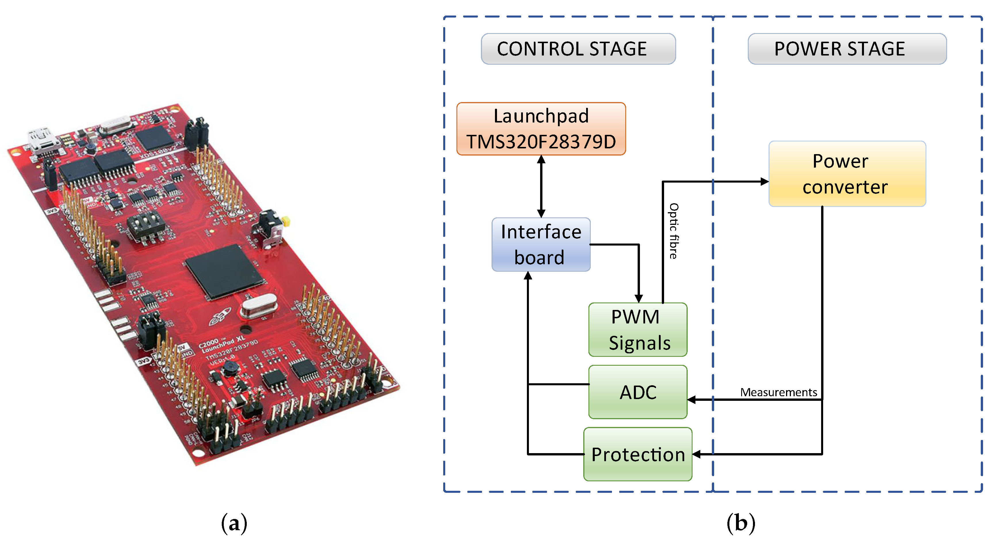
The proposed RTCP is equipped with the launchpad LAUNCHXL-F28379D of Texas Instrument. This launchpad is based on a 32-bit floating-point Delfino microcontrollers, model TMS320F28379D, which is designed for advanced closed-loop control applications. The Delfino launchpad LAUNCHXL-F28379D is shown in
Figure 1a and its key features are described below:
Dual-Core architecture with two TMS320C28x 32-Bit CPUs;
200 MHz Clock;
1 MB Memory flash;
Analogue and control peripherals include Digital Analog Converter (DAC), PWM, Enhanced Capture (eCAP), Enhanced Quadrature Encoder Pulse (eQEP), and other peripherals;
USB, CAN, I2C and SPI interface;
24 Analogue-to-Digital (AD) signal channels with 12 or 16 bit resolution;
24 PWM channels with 16 bit resolution and dead time support.
The proposed RTCP expands the launchpad capabilities through the implementation of an expansion board, as shown in
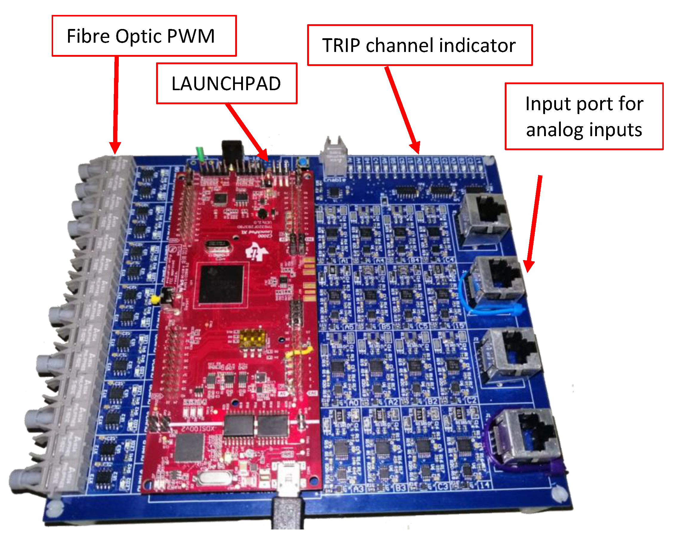
Figure 1b. The RTCP provides optical fibre interfaces that can be used to transmit PWM signals, it performs signal conditioning to measure analogue signals, and it provides hardware protections. All the protections are cascaded to interrupt the operation of the converter if over-voltages or over-currents arise. The expansion board is presented in
Figure 2. It is a four-layer PCB (Printed Circuit Board) measuring 179 × 156 mm. Its main components are drivers for an optical fibre interface, operational amplifiers for analogue-digital conversion, and comparators and logic gates for hardware protection. The total RTCP cost is approximately USD 400, as presented in
Table 2, and it considers the cost of the Delfino Launchpad, plus the expansion board assembly and electronic components.
The principal features of the proposed RTCP are listed below and they are detailed in the next subsections.
14 PWM channels with optical transmitters;
16 AD channels with 12 bit resolution;
16 hardware protections implemented with digital potentiometers;
Dedicated connector to access USB, CAN, I2C and SPI communication in.
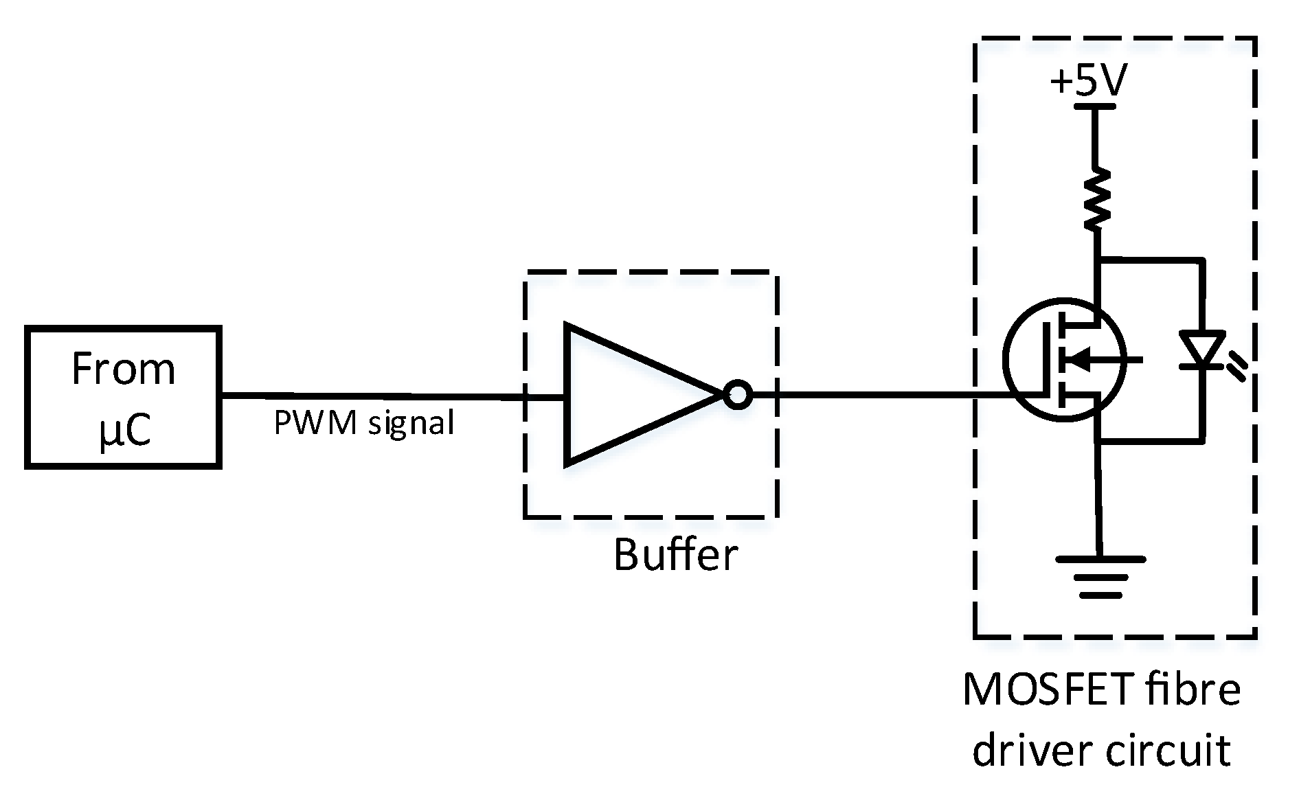
2.1. Electrical/Optical Stage for PWM Signals
The PWM signals generated by the Launchpad are sent to the power stage by optical fibre interface. For this purpose, the expansion board considers drivers for each PWM signal. The optical fibre interface circuit is shown in
Figure 3. Each driver is composed of a low-input impedance buffer connected to the gate of a MOSFET that switches on and off to activate the optical fibre. The microcontroller is capable of generating PWM signals up to 100 MHz. Notice when increasing the PWM frequency reduces its duty cycle resolution due to the 200 MHz system clock of the microcontroller.
Using the optical fibre interface to send the PWM signals has advantages such as noise immunity and electrical isolation between the control and the power stage [
21,
22]. Is important to notice that the TMS320F28379D chip is capable of generating 24 PWM signals. However, the Launchpad board is available with only 14 of them. For that reason, 14 optic fibres were considered in the final design of the board.
2.2. Adaptation Stage for Analog Input Signals
The measurement of analogue signals requires an adaptation stage to match AD capabilities. Therefore, processing of the AD signals is performed scaling and applying offset to the original signals. The range of the final signal is defined between 0 and 3 volts not to saturate the AD converter.
Figure 4 presents the electrical circuit used in the AD conversion. The TMS320F28379D chip consists of 4 independent Analog Digital Converter (ADC) channels. Each of them is capable of measuring six multiplexed signals allowing the microcontroller to read a total of signals. However, the Launchpad board provides 16 of them. For that reason, 16 analogue measurements were considered in the final design of the board.
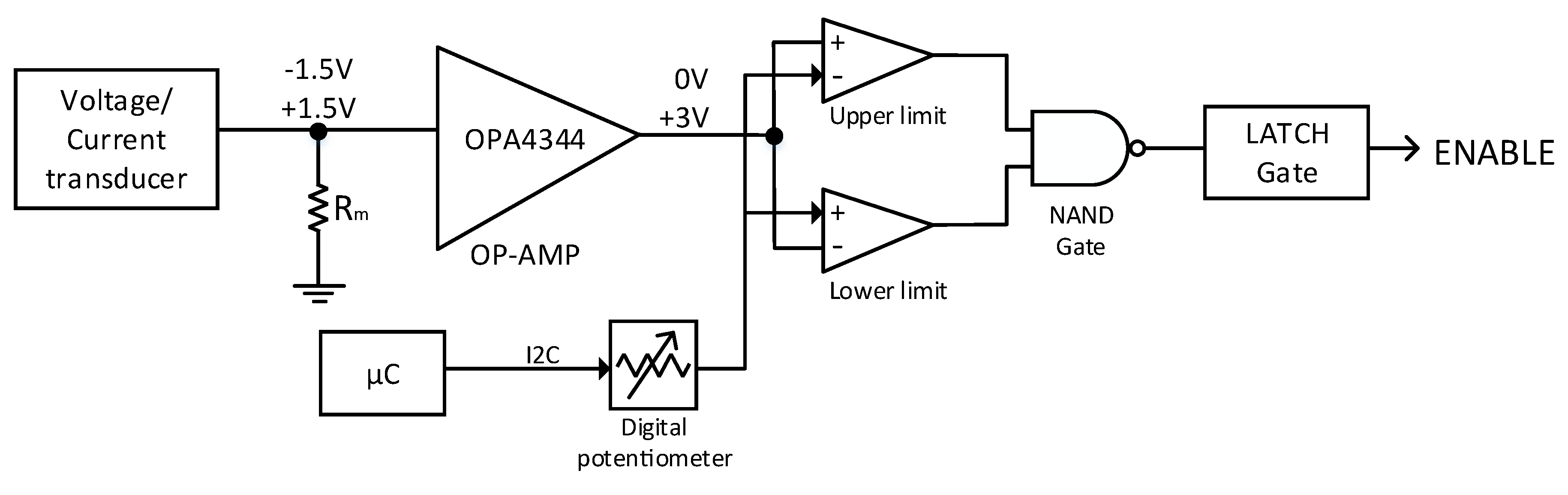
2.3. Hardware Protections
A protection circuit based on digital comparators and potentiometers has been implemented on the interface board. The main goal of these circuits is to protect the power converter from over-voltage or over-current events.
The comparators receive a reference signal generated by a voltage divider. The digital potentiometers can be regulated to adjust this reference signal. Then, the reference is compared to the analogue input signal, as shown in
Figure 4. If the defined thresholds are exceeded, the comparator generates a warning signal and deactivates the switching devices. LEDs located on the side of the board indicate which channel was tripped. To modify the values of the digital potentiometer, the new data must be sent from Matlab Simulink to the board through I2c communication.
2.4. ADC Configuration
In power electronic applications, usually, the RTCP execute control algorithms in a closed-loop manner. This means that the RTCP must first read the AD signals, i.e., voltages and currents, and depending on these values, to execute the algorithm. Then, the references for the PWM modulation and the switching signals are updated. Hence, it is imperative to know the controller computing capacity, as well as the technical characteristics of the AD and PWM interface, to ensure proper execution of the control algorithms.
The power converters incorporate a voltage and current feedback requiring analogue inputs. For this requirement, the controllers typically include embedded AD converters to convert the analogue voltages and currents into digital variables to be interpreted by the microcontroller.
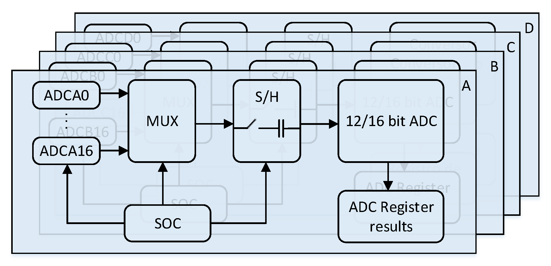
The TMS320F28379D microcontroller incorporates 12-bit or 16-bit AD channels with 1.1 or 3.5 Mega Samples per Second (MPS) capability. The AD conversion can be set in a single-ended or differential configuration. Internally, the microcontroller has four independent AD channels labelled A, B, C and D, which allows reading four signals simultaneously. Using multiplexing, the microcontroller can read up to 24 analogue signals.
The ADC configuration is presented in
Figure 5. Each analogue signal is read by one of the blocks whose execution logic is defined by Start-Of-Conversions (SOC). The SOC defines the source that triggers the AD reading, the channel to be converted and the acquisition interval.
Subsequently, an acquisition interval is defined. The acquisition interval is the amount of time needed by the sampling capacitor is enabled to charge. This mechanism allows retaining the data for a time specified by the user (S/H Sample and Hold). Typical acquisition values range from 10 ns to 500 ns.
Finally, the AD block processes the data and save it in a register. This register can be accessed by the microcontroller to execute the control algorithm.
2.5. PWM Configuration
The PWM is one of the essential peripherals of a microcontroller since it provides the necessary signals to command the power devices (typically MOSFET and IGBTs) using a gate driver. This driver must be able to provide galvanic isolation between the control and power stages and generate the appropriate voltage to turn on-off the devices.
One of the requirements of the PWM peripheral is that it must generate signals with precise pulse width and high resolution with minimal CPU usage. For this purpose, the TMS320F28379D chip incorporates a peripheral capable of generating the PWM signals. This peripheral is easy to program, highly flexible and only requires a message from the CPU to update its new value.
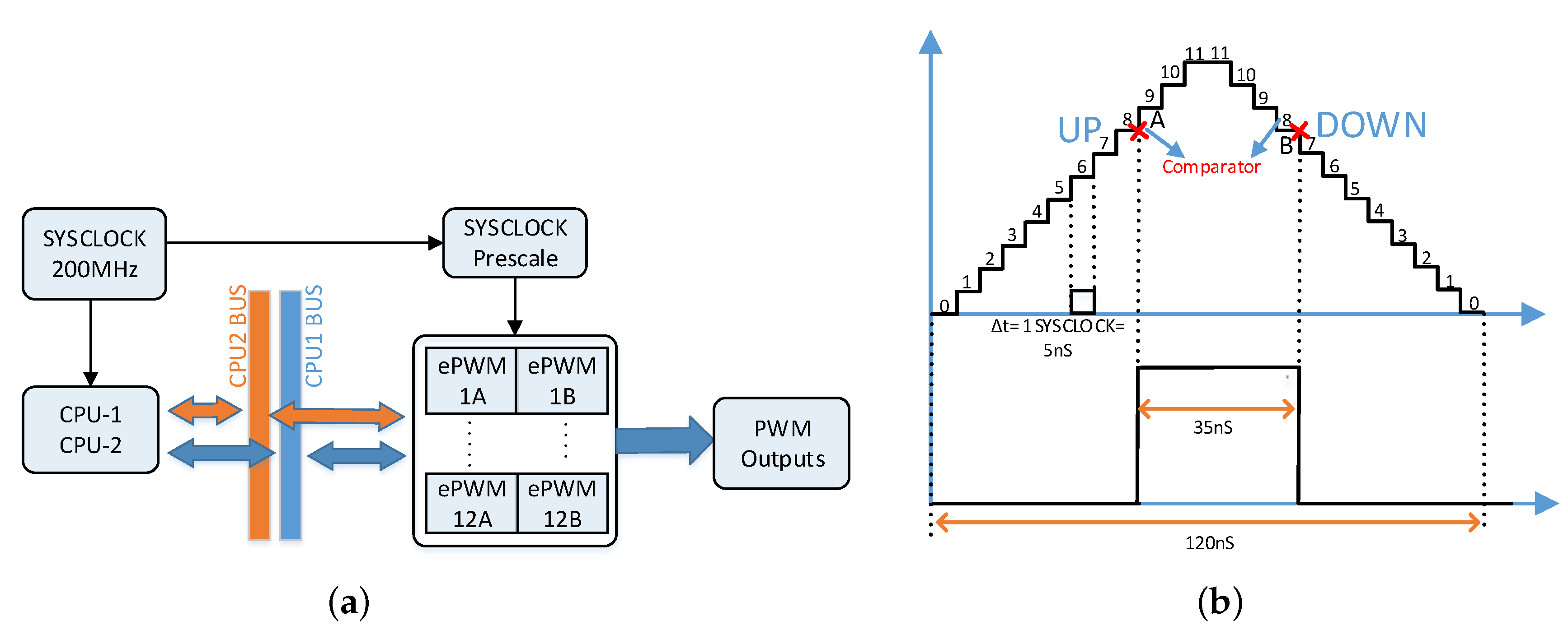
The TMS320F28379D chip contains 12 independent PWM blocks of 16 bits each. Counters and comparators, define the frequency and duty cycle of the PWM, respectively.
Figure 6a shows the operation of the PWM block. Each PWM block consists of two submodules, namely submodules A and B, that provide a total of 24 PWM signals. The submodules can be configured as complementary signals, meaning that A is the boolean negative of Besides, it is also possible to set dead times between them, which is a useful function to manipulate two IGBTs of a single leg. The communication between the CPU and the PWM block is done through a common bus where information is shared. This information can be continuously updated in real-time as necessary, either to modify the pulse width of the PWM, its period or another parameter.
For a basic configuration of the PWM blocks, the input parameters are to the counter and the comparator. The counter is an integer between 0 and 65,535 that represents the counts that will be made in clock cycles. The crystal frequency determines the clock cycles. This crystal is 200 MHz which means that each account is equivalent to a period of 5 ns.
The behaviour of the counter can be set as Up-Down, Up and Down. In the Up-Down mode, the counter starts counting from zero until it reaches the defined setpoint. Once it reaches the value, it returns with a descending counter until it reaches zero and then repeats the process indefinitely. On the one hand, the Up mode starts with an ascending count from zero until reaching the defined number repeating the process. On the other hand, the Down mode counter behaves like the Up counter but in the opposite way, starting with the maximum count and then descending until it reaches zero.
The comparator is an integer value between zero and the maximum count value. This value can be set by the user or be continuously refreshed as needed. When the counter reaches the comparison value, the user can trigger different events pulling the PWM signal in high or low. The example in
Figure 6b shows an Up-Down counter of 11 counts and two points of comparison. The signal is set to low when the counter is equal to zero, set to high when it reaches comparator A and then set to low when it reaches comparator B.
The signal generated in
Figure 6b is a high-frequency signal since a small number of clock cycles were used for illustrative purposes. For lower order frequencies, a higher counter can be set, or the SYSCLOCK (oscillator frequency equal to 200 MHz) can be scaled to half its frequency, decreasing the PWM frequency by half.
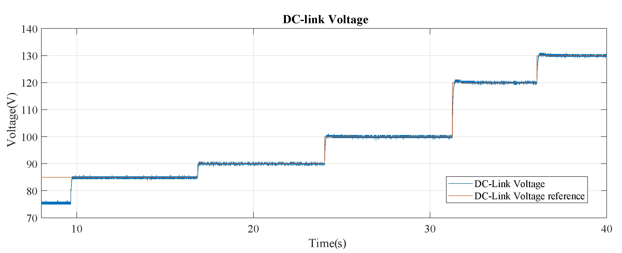
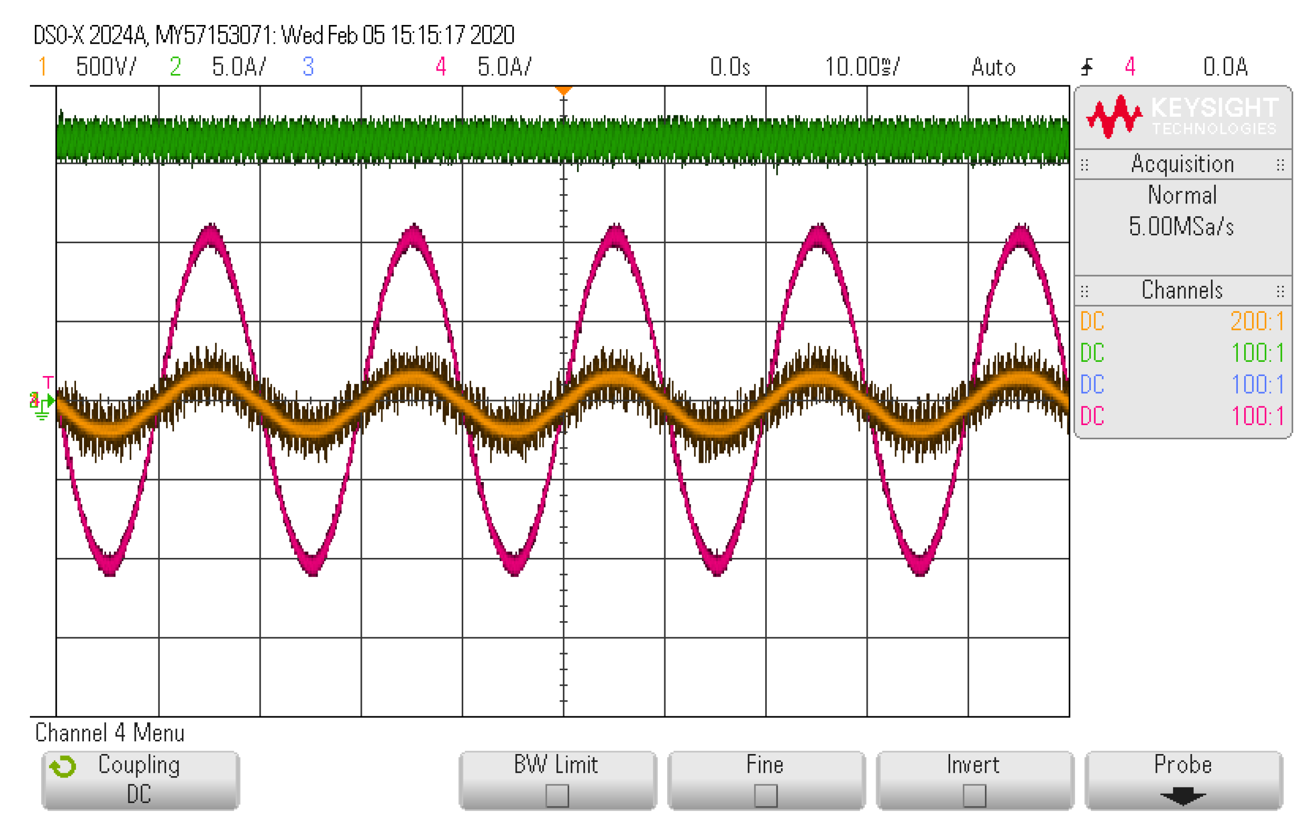
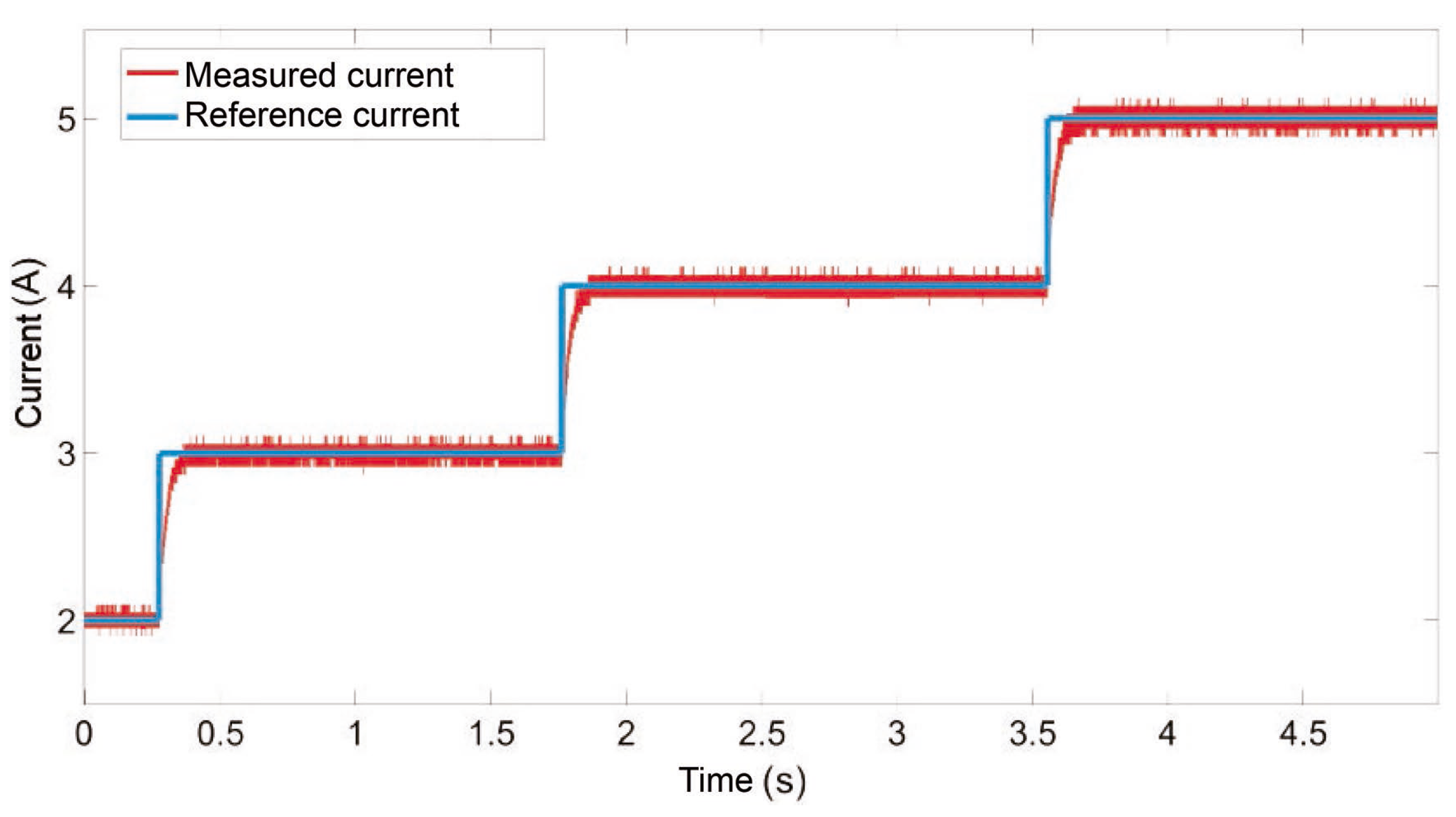
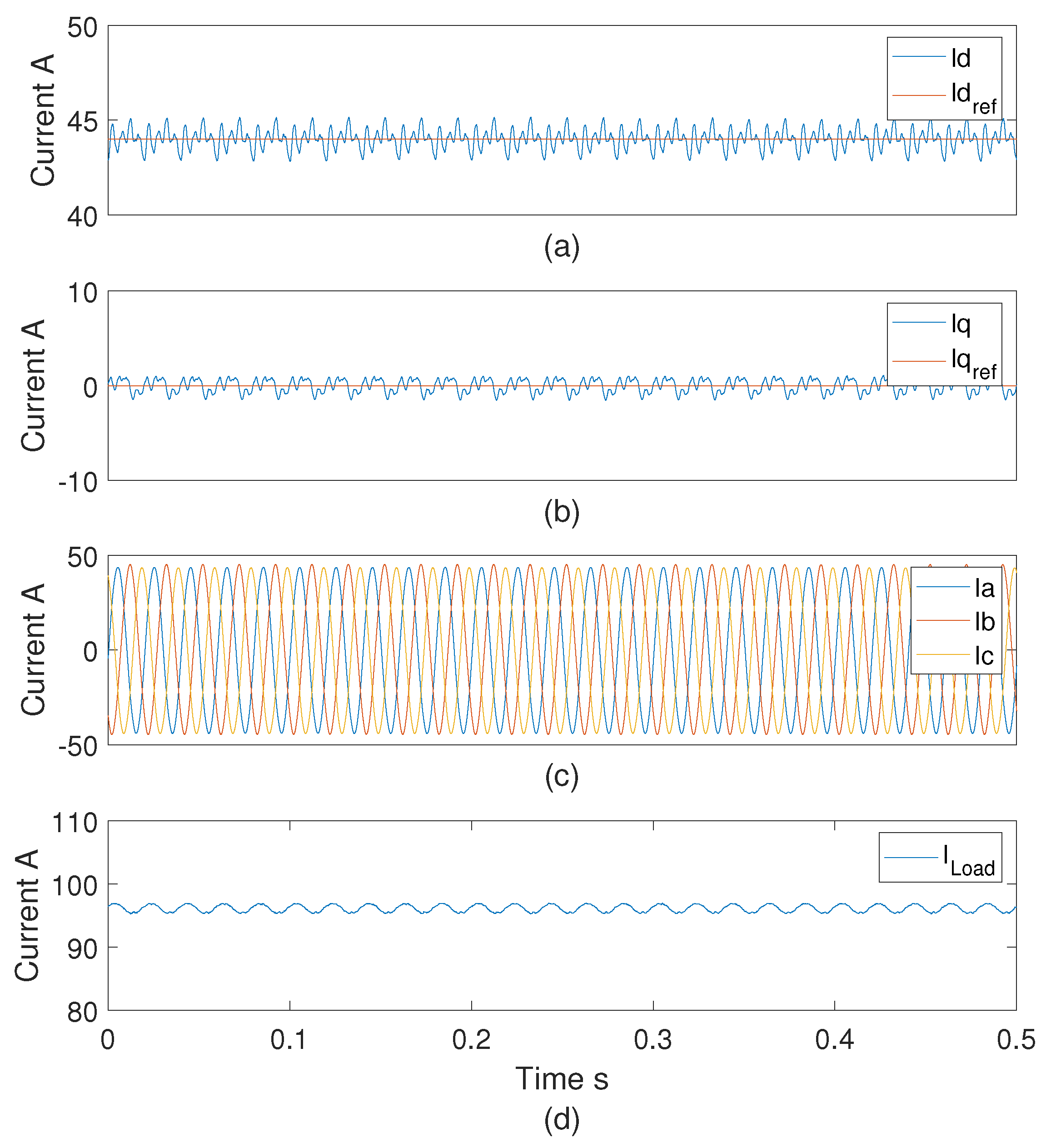
3. Power Electronic Application to Test the RTCP
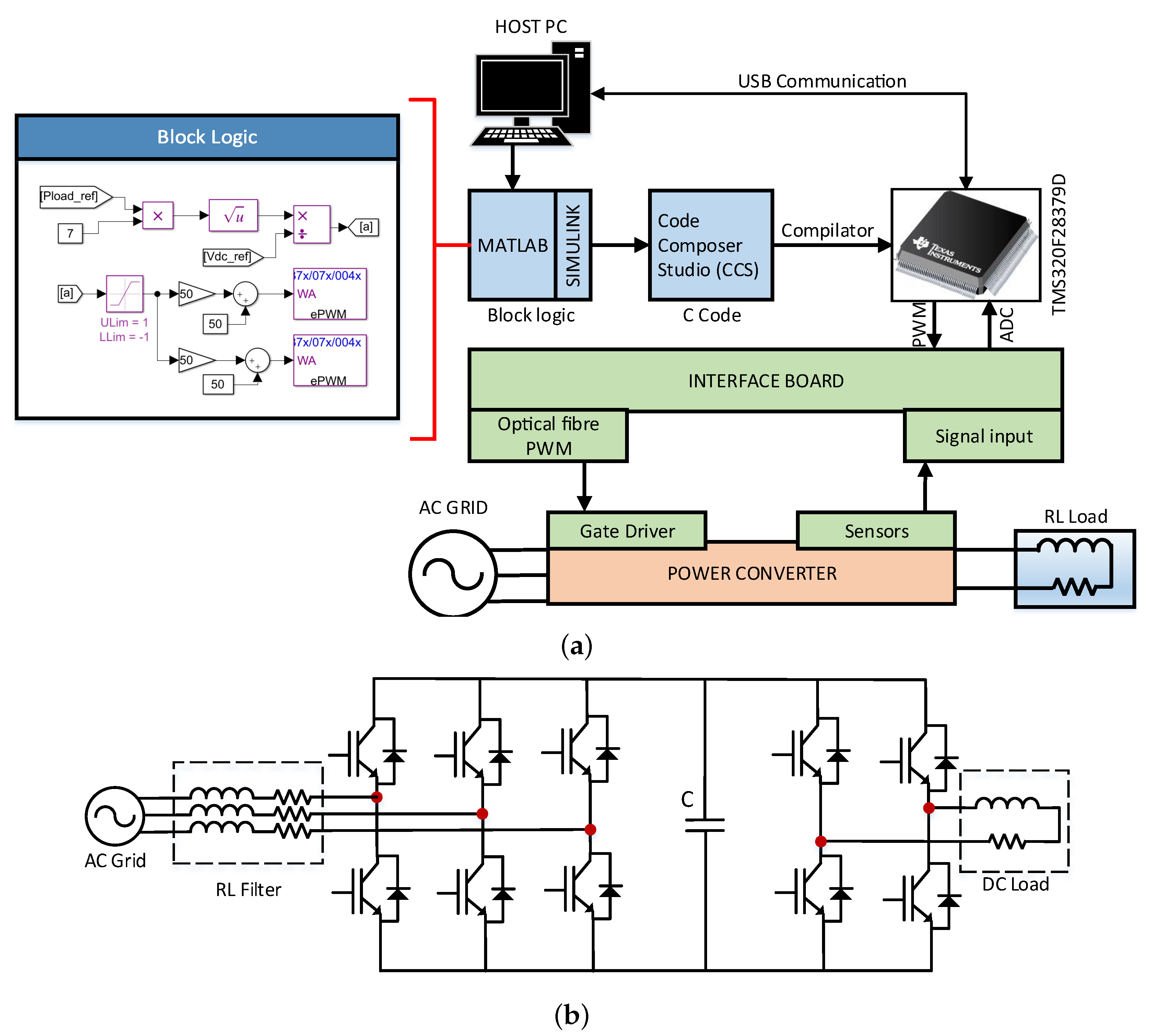
The performance of the proposed RTCP for power electronics RCP applications is validated using the scheme presented in
Figure 7a. The proposed RTCP is used as RCP to control a generic power converter. In this case, an AC-DC back-to-back converter is utilised as an example. The power converter is used to transfer power from an AC grid to a DC Resistive-Inductive (RL) load. The AC-DC back-to-back converter is composed of a controlled rectifier equipped with IGBTs, and a DC-DC converter based on a full-bridge, as shown in
Figure 7b.
The RTCP has a direct interface to a computer, and it can be programmed in C/C++ using Code Composer Studio. Additionally, it has MathWorks Embedded Target Support for easy programming and debugging in Simulink. The launchpad LAUNCHXL-F28379D has a predefined blocks library that can be accessed from Texas Instrument website [
23]. Additional self-designed control blocks can also be used and mixed with the predefined block from Texas Instrument library.
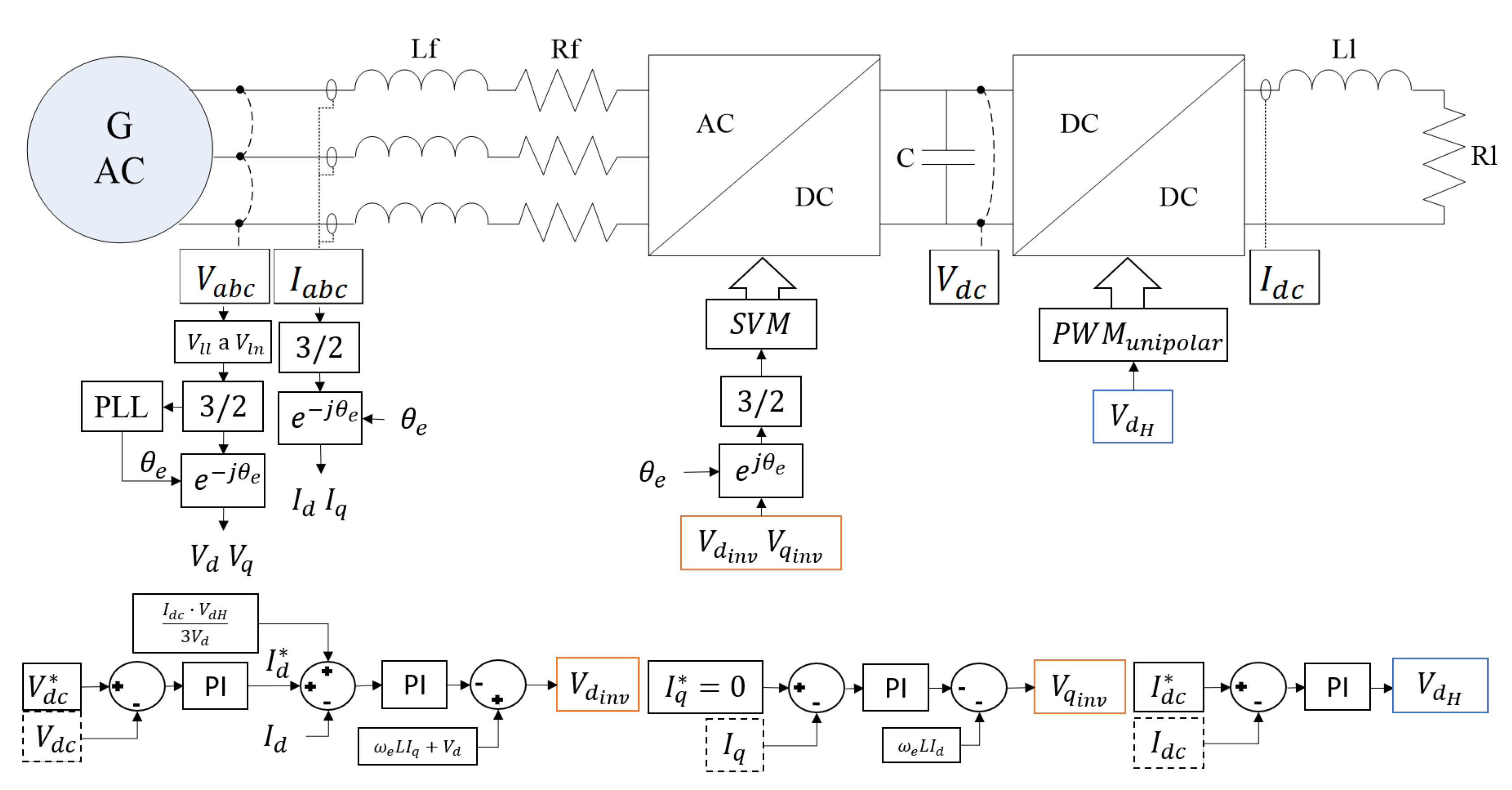
To control the AC-DC back-to-back converter, the control strategy displayed in
Figure 8 is programmed in the RTCP. The converter is regulated to operate as an interlinking AC-DC converter to achieve AC-DC power transference [
24,
25]. The controlled rectifier is regulated using a dq control strategy and a Proportional-Integral (PI) controllers as proposed in [
26,
27]. Additionally, the full-bridge is operated in grid feeding mode, and the DC current is regulated using a PI controller. Both control strategies are linked through the feed-forward shown in
Figure 8. The parameters used in the PI controllers are shown in
Table 3.
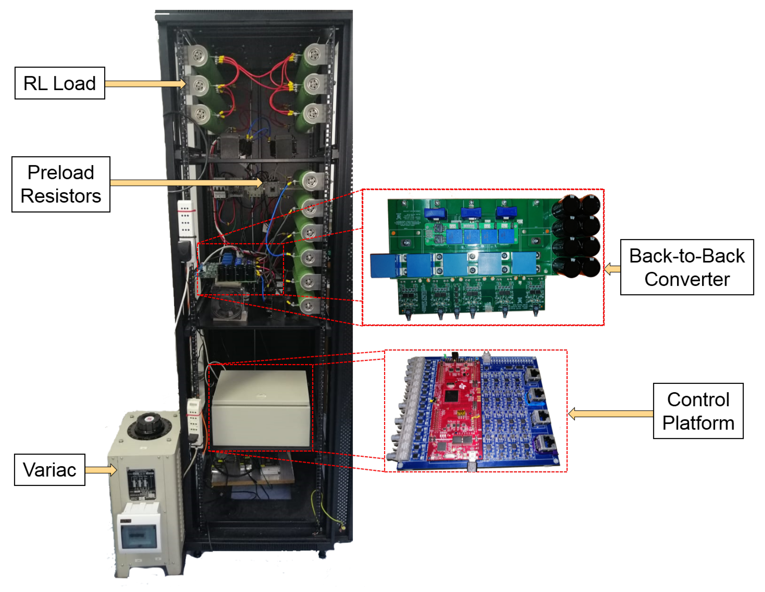
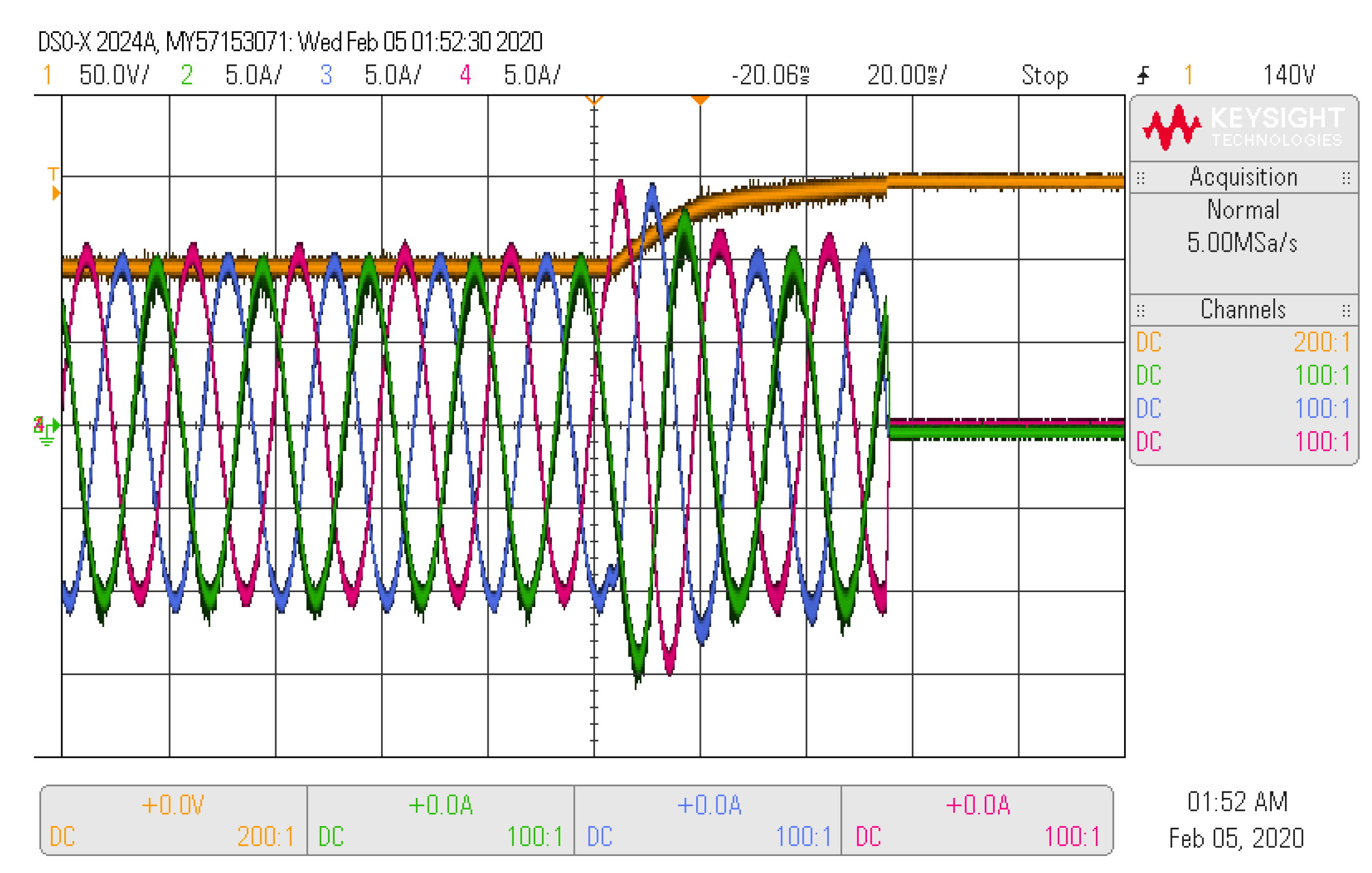
The implemented experimental system is shown in
Figure 9 where the power converter, control platform and RL load lays inside. A metal box covers the control platform for noise immunity. A Variable AC source is used to work with variable voltage in the AC side. The main parameters of the power converter are specified in
Table 4. The AC-DC controlled rectifier is equipped with Infineon IGBTs, model FF75R12R74, with a nominal current of 75 A and an emitting collector voltage of 1200 V. The DC-DC full-bridge is equipped with Infineon IGBTs model FF300R12KT4, with a nominal capacity of 300 A and 1200 V. Both devices have a modular packaging that contains two IGBTs that form a converter leg. Finally, it is worth to mention that the DC-Link has a capacity of 2 mF and supports 800 V.
5. Conclusions
The design and implementation of a new RTCP for power electronic applications have been presented in this paper. The proposed RTCP is composed of the Launchpad TMS320F28379D and an expansion board to provide analogue measurements, switching signals and hardware protections. The expansion board is equipped with optical fibre drivers for 14 PWM signals and an AD conditioning interface for up to 16 analogue signals. Additionally, each AD channel is equipped with hardware protections to prevent any potential damage in the power stage.
If compared to all the current off-the-shelf solutions on the market, the proposed RTCP offers is a cheaper solution that offers a good trade-off among cost and capabilities, targeting at the segment in between expensive off-the-shelf control platforms and low-cost controllers. The RTCP features easy-to-use and straightforward programming, which is very useful for RCP applications.
Due to its capabilities, the proposed RTCP can be used as RCP in a wide range of teaching and research applications. For instance, it is expected to use it to control interlinking converters in AC-DC microgrid applications, interconnection of renewable energy generation units, and variable-speed drive for electrical machines.


 ,
, 


