1. Introduction
For most small- and medium-scale applications of gasification technology, the gasified feedstock is either bio-based or, more preferably, derived from waste feedstocks such as solid recovered fuel (SRF), lignin, or sewage sludge [
1,
2]. In the case of most waste-derived feedstocks, the step of their thermochemical conversion is more demanding than commonly encountered for conventional, clean biomass. The problems are mostly encountered in the operation of reactors; however, the use of waste materials also introduces major changes in the way the syngas needs to be purified. Importantly though, where the control and efficiency of a gasifier is the most important aspect for the operation of any gasification installation, it is the possibility to clean the produced syngas that renders the whole operation economically and environmentally sound. With the increasing complexity of syngas application, the complexity of its purification also increases. In general, direct combustion requires only marginal gas cleaning, which can often be limited merely to dedusting in cyclones, while, for reciprocating or gas-turbine engines, complete removal of fines, deep removal of condensing species (tars, light organics, and water), and careful control of the content of acidic species are demanded. By far, the most advanced applications of syngas are chemical synthesis (methanation, Fisher-Tropsch) and fuel cells, both of which demand almost complete removal of any contaminants [
3]. It is compulsory, then, to devise such gas cleaning systems so that three major goals are simultaneously obtained. The first is to achieve the required cleanliness of the gas. The second is to perform the process with the least environmental impact, while the third connects with the economic aspect of the investment. Thus, the third issue not being technologically limiting remains crucial when developing new technologies.
Due to the progress achieved in gasification and gas cleaning technologies over the past 30 years, today, we most often see that it is the economy that holds back the development of many gasification installations rather than their technical or technological limitations. The fact is that, depending on a given case, from technological and technical standpoints, different feedstocks perform better in different types of reactors. Thus, the choice of gasifier can determine the whole installation’s success or failure. Furthermore, gas cleaning units are developed for a given gasifier and feedstock, not vice versa. It is also well established that gas cleaning with a combination of the following methods provides the best performance in the widest area of syngas cleaning applications: catalytic upgrading, high-temperature (HT) dedusting on barrier filters, wet scrubbing, and final polishing with dry adsorption methods [
4]. These advanced solutions are compulsory for high-value end products obtained from syngas. However, at the same time, they tend to lower the profitability of installations in applications where low-value products, such as heat and power, are produced. Currently, in many developing countries such as Poland, it is the eco-friendly, renewable generation of electrical power that shapes the scene in terms of political decision-making and market development initiatives much more firmly than the drive toward, e.g., production of liquid biofuels. To make progress in the amount of waste biomass, SRF, or sewage sludge utilized for power generation, it is vital then to take advantage of small- and medium-scale distributed gasification installations, which offer better efficiencies, flexibilities, costs, and environmental impact than conventional combustion methods. For these reasons, development of gas cleaning methods that provide the above-mentioned benefits needs to be done.
The article describes the concept of an adsorption technology tested for HT cleaning of syngas derived from the gasification of biomass. The concept is based on the use of a multi-component cleaning method performed in one reactor vessel, where a hot-gas ceramic candle filter is precoated with naturally occurring cheap and abundant minerals. Multi-component cleaning solutions greatly improve the reliability and efficiency of thermochemical conversion plants, while also lowering their footprint. HT, raw syngas coming out from a reactor contains the highest amount of contaminants, which makes its cleaning most efficient. Furthermore, because HT dedusting is most of the time the first step of syngas cleaning, it is interesting to develop a method for simultaneous removal of not only dust particles but also other contaminants. For this reason, it is proposed to inject adsorbents upstream of ceramic filters and, thus, to conduct the adsorption process on a continuously regenerated bed of filter cake composed of char, ash, and the adsorbent material itself. This concept has multiple potential merits. The most important ones are the complete removal of solids and the possibility to reduce the amount of Cl, S, and tar species.
Firstly, it is noteworthy that, after the gasification process, both chars and ashes entrained in syngas have substantially activated surface area and, thus, can act as a sorbent for contaminants. This phenomenon is currently thoroughly researched since major improvements in fixed-bed gasifiers are possible this way. Nakamura et al. [
4] proposed the use of gasification by-products as a means for process gas cleaning. In the system, the use of water–tar condensate as a washing medium in a scrubber and char in the form of a fixed-bed adsorber was tested. The results showed that the scrubber efficiency for tar removal reached its optimum at 50%; however, the efficiency of the char adsorber reached over 81%. Furthermore, Yafei et al., in their work, reviewed and studied the concept of closing the management cycle for tar, char, and heavy-metal gasification by-products through integrated concepts [
5]. In the study, the pathway for using gasification- or pyrolysis-based chars as support for adsorption of heavy metals and their subsequent use (after deactivation) for catalytic elimination of tars was presented. Finally, the closure of the tar/char management cycle was proposed through the use of catalytic gasification of the spent catalyst. In this way, it is possible to recover C from the catalyst as syngas and the heavy metals as bottom ash. However, the most straightforward and visual way of using creative design of thermochemical processes to use the characteristics of gasification char was presented by Obernberger et al. [
6]. The study showed that it is possible to use a two-stage gasification–combustion method for the energetic use of waste biomasses of low ash melting temperatures for highly efficient generation of heat with unprecedentedly low emissions of CO, total organic carbon, and particulate matter. Here, the process layout resembles a common updraft gasifier with a gas combustion chamber that is fitted just above the fixed bed. However, the obtained in-bed temperature profile is distinctly different for the char/biomass bed to act as adsorber/filter and not to produce excessive amounts of tars, as is often encountered in conventional updraft gasifiers.
Furthermore, process conditions where most syngas ceramic filters are commonly operated induce the need to use auxiliary co-filtering materials in the first place. The inert materials increase the filter’s particle collection efficiency, as well as keeping the pressure-drop low. Such inerts are mostly based on fine powders composed of SiO or CaO. Through this “co-filtration” effect, it is often possible to keep dedusting of hot syngases stable, where filtration of char alone leads to a constant rise of pressure drop on the filter. Due to its higher thermal stability and flowability, the inert material eases pulse-back regeneration of the filter, while collecting part of the polymerizing tar and condensing mineral matter, thus preventing the clogging of filter pores. By changing the inert solid for materials that exhibit chemical activity in the process condition, it is possible to perform high-temperature, dry scrubbing of syngas.
In the proposed system, the sorbent is injected upstream of the ceramic filter through a Venturi nozzle. This method assures good mixing of the solid and syngas in the turbulent region of the filter intake. In the first step, the adsorption takes place in a diluted two-phase system, where contact time is extended by the design of the dirty plenum of the filter. Importantly, the particle size distribution of the sorbents needs to be controlled to avoid disengagement of the sorbent from syngas before reaching the surface of the filter cake. The adsorption process is finalized in thorough cleaning on a fixed-bed layer composed of the filter cake which collects on the surface of the ceramic filters. When adsorption on the filter cake is considered, a few differences render the process distinctive from a conventional adsorption set-up. Firstly, filters applied in the filtration of gases are mostly developed to operate at as high linear gas velocities as possible (face velocity). However, in HT applications, to keep them stable, the units need to be run in the range of face velocities much lower than nominal for low-temperature bag filters. Values from 0.5 to 3.0 cm/s often provide the lowest operational and investment costs for hot gas filters, while keeping the process stable. In adsorption processes, hourly spaced gas velocity (HSGV) can be thought of as a parameter comparable to face velocity in filters because, here, the filter cake is the active bed composed of the sorbent material. For adsorption to be efficient, the HSGV in fixed-beds should be kept in the range from 0.2 to 0.5 m/s with a contact time of approximately 3 s [
7]. To get close to the above-mentioned standards, it is necessary to lower the filtration velocity to minimal values and increase the thickness of filter cake. In practice, reaching the benchmark with the use of ceramic filters is technically impossible.
For the pilot installation used in the research, the ceramic filter integrated with the pilot GazEla gas generator was designed to be operated at 0.5 to 1.0 cm/s. Depending on the operational conditions of the filter, the thickness of its filter cake should range from 1 mm for freshly pre-coated new filters up to 6 to 8 mm when the filter is run with candles not regenerated regularly. Realistically speaking, this set-up may provide from a minimum of 0.2 s up to a maximum of 1 s of contact time between the gas phase and solid phase of the filter cake with an average of 0.5 s. Such residence times should be considered as low values for fixed-bed adsorbers; however, they are more than reasonable for many fluidized bed (FB) units [
7]. In the proposed system, the first stage of adsorption resembles FB adsorption in a diluted circulating fluidized bed (CFB), as the adsorption process starts from the moment the sorbent is injected into syngas. For the pilot installation, the contact time for the first stage of adsorption can reach up to a few seconds depending on the reactor power.
The second reason why the HT filtration/adsorption system cannot be directly compared to any of the two above-mentioned systems is the particle size of sorbents that build up the filter cake. Preferably, for the filter, the sorbent particle size distribution should range from 15 to 50 μm, which makes it 10-fold smaller than sorbents used in FB reactors and more than 1000-fold smaller in comparison to fixed-bed units.
Moreover, it is important that, after a regeneration cycle takes place, part of the surface of the filters is stripped of the filter cake. If the regeneration is too harsh, the thickness of the cake may be reduced to the point where both particles and other contaminants slip through the filter, thus impairing the efficiency of cleaning. Furthermore, as mentioned above, the filter cake only partially consists of the dedicated adsorbent, whereas the rest of the cake is composed of char and ash filtered from the syngas. Both ash and char are transported through a gasifier; thus, their surface is activated to some extent, which has a positive effect on the adsorption efficiency. Sorption in the filter cake also brings forward another relation. The thickness of the cake positively influences the efficiencies of both dedusting and adsorption, while increasing pressure drop (dP) across the vessel. Thus, the importance of precise control of the regeneration process is vital here.
Research presented in this paper focused on the collection of process data and operational experience. However, to assess the efficiency of the method, it also leaned into the determination of adequate analytical procedures. In contrast to flue gas cleaning systems, the problem of qualitative and quantitative determination of cleaning efficiencies of syngas cleaning units is still demanding and by no means should be regarded as trivial. This issue is even more pronounced when research is performed in real conditions and on a small scale, which brings forward many technical limitations that are not present in lab-scale installations.
The extent to which the syngas needs to undergo cleaning is determined by the type of feedstock, the type of gasification reactor, and the of the final application. Generally speaking, when the reactor is treated as an equilibrium black box, its products are always the same and depend only on process efficiency, temperature, pressure, type of gasifying agent used, etc. Thus, models often do not take into account the recognition of the type of gasifier used. However, in reality, differences between the gasification processes run at fixed, fluidized, or entrained beds are substantial and decide the composition of generated syngas. As far as contaminants of syngas are concerned, their generation in gasifiers takes place mainly due to volatilization from the solid phase and subsequent gas–gas and gas–solid reactions. Due to different process conditions taking place in gasifiers, differences in syngas composition are pronounced. For fixed-bed reactors, a readsorption of contaminants on activated char and ash present in the bed is observed [
8]. For FB, on the other hand, the amount of char in the bed is small, but the bed is often composed of a material which can influence the process through catalysis or sorption. For example, in FB reactors, olivine is a frequently used as a bed material for in situ tar reforming, and CaO beds are used for CO
2 removal from syngas [
9,
10]. Finally, entrained flow reactors are operated at very high temperatures that can lead to very clean syngases through the almost complete conversion of tars and collection of containments in the form of vitrified slag [
11]. For the Institute for Chemical Processing of Coal (IChPW), the choice of fixed-bed reactor systems was done based on the scale of solution sought by the market and the intrinsic characteristics of fixed-bed units, meaning their ease of operation, robustness, flexibility, and ability to use the bed for active removal of contaminants from syngas. In fixed-bed reactors, char is activated by process conditions and acts as the sorbent material. For example, in laboratory conditions, it was shown that, inside gasifiers, chlorine can be almost fully volatilized (>90%) from fuel and, thus, is a constituent of raw syngas. In the case of S, it rarely undergoes complete volatilization in the reactor and, on average, 50% of S from biomass remains in the bottom ash from the reactor even at temperatures reaching 1000 °C [
12]. On the other hand, alkalis, such as potassium, almost exclusively volatilize with correlation to Cl. Therefore, if Cl content of the biomass is low, K mostly remains in the bottom ash. Other elements that tend to volatilize under gasification conditions are mainly Na, Ca, Si, Mg, P, and Al; thus, in this research, their content in the filter cake was the subject of examination. Okuno et al. [
13] suggested that alkali and alkali earth metals (AAEM) leave gasifier mostly in correlation with water-insoluble tar and, thus, with aromatic compounds that are derivatives of benzene, xylene, furfural, and naphthalene in the syngas [
14,
15]. These compounds remain gaseous under gasification and HT gas cleaning conditions; hence, their enhanced recovery in filer cake is a sign of adsorption from the gas phase. Moreover, Sonoyama et al. [
16] showed that AAEM species have high affinity to bonding with char in fixed-bed conditions unless the flow of gas is significant enough to force them to pass through the bed. In their research, helium was used as the carrier gas; however, the principle also applies to the research presented in this paper. These results showed that volatile AAEM species undergo repeated adsorption/desorption cycles on the surface of the char bed; thus, their readsorption on filter cake should also be visible. In the study, the authors experimentally verify the theoretical possibility of removing the following contaminants from syngas with the use of a combined process of HT filtration and sorption: hydrogen sulfide, hydrogen halides, ammonia, AAEMs, heavy metals, and tars on the surface particles collected in the filter cake.
3. Experimental Installation
The experimental set-up utilized for this research was localized in the Center for Clean Coal Technologies in Zabrze, Poland. The installation was based on a pilot GazEla reactor. The gasifier is a fixed-bed, mixed-flow reactor, where fuel is fed from the top and an air/steam mixture is introduced into three characteristic zones of the bed. The innovative part of the reactor is a method for the recovery of hot syngas directly from the gasification zone. For the gasification of biomass, the reactor is characterized by 60 kW
th input and a cold gas efficiency (CGE) of ca. 67%. More results regarding the gasification of various fuels and a detailed description of its operation can be found in the literature [
1,
2].
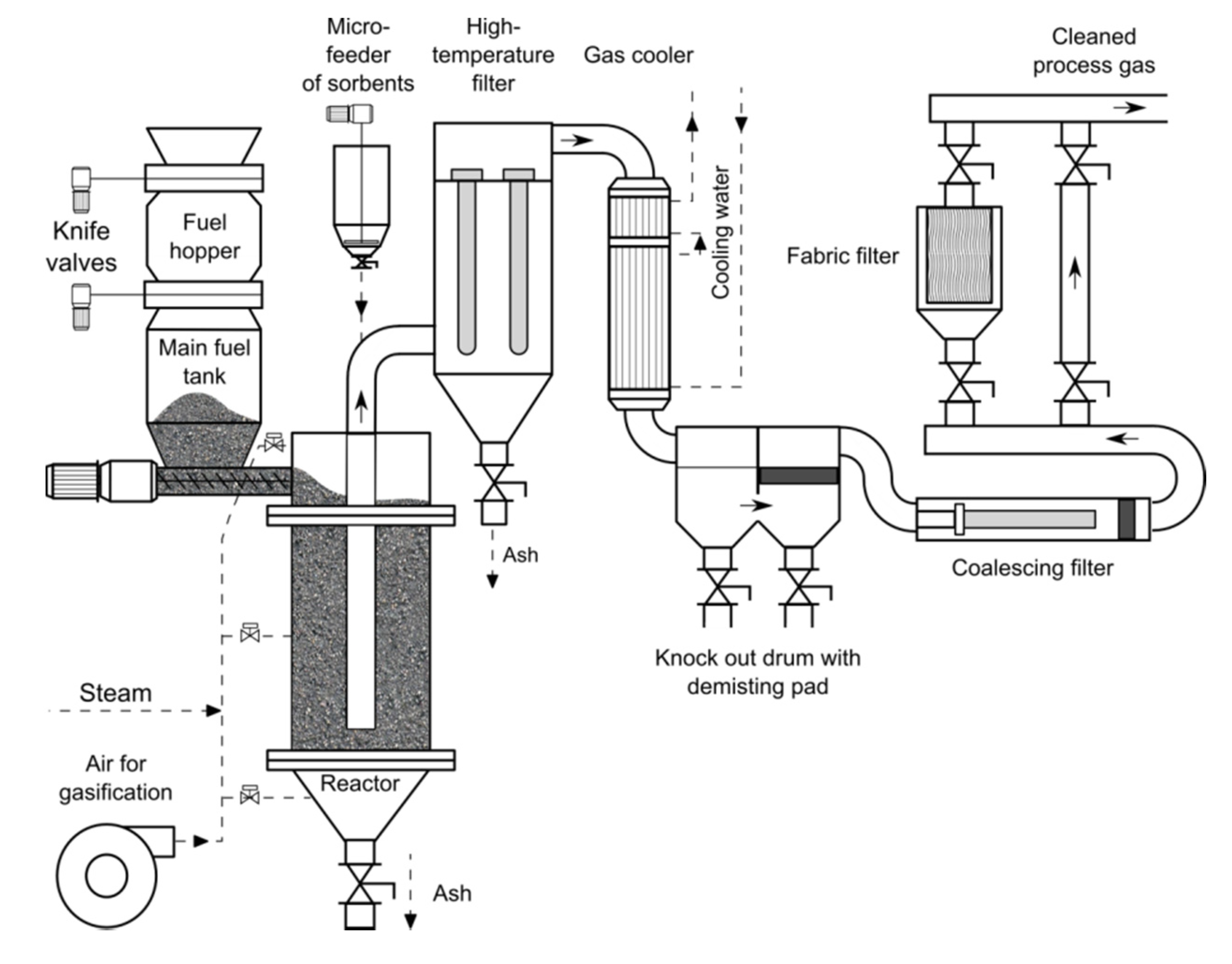
The pilot installation was also devised for conducting research on different configurations of gas cleaning methods and, thus, the reactor was simultaneously connected to both dry and wet gas cleaning installations. As the main goal of this research was to develop a method for HT filtration and sorption of syngas, results presented here were obtained from one configuration of the dry gas cleaning route. Downstream of the GazEla reactor, raw syngas, at 450–550 °C, is directed toward the inlet of a ceramic filter. Before the filter, sorbents were injected into the syngas.
Because the sorbent plays here a double role, its particle size distribution was set such that it produces a well-structured filter cake of uniform porosity while creating a uniform, stable aerosol of the sorbent at every point of the filter. Thus, the largest particle size of sorbent was set such that, in the largest cross-section of the filter, the sorbent should not settle from the gas, but rather be entrained with the flow of syngas until its separation on the filter cake.
The filter is conventionally separated into two zones by a horizontal plate that supports the filter candles. Gas enters the dirty zone. When it travels through ceramic candle filters, it is dedusted and cleaned. For the pilot installation, the filter is composed of 10 ceramic filters (1 m long, 60 mm in outer diameter) divided into two cleaning sections. After passing through the candles, the dedusted gas enters a clean zone of the filter and passes to a next cleaning unit. During this research, the dedusted gas subsequently underwent cooling down from ca. 450 °C down to 40 °C for condensation of water and organic matter. After cooling, cold syngas contains a lot of water–tar mist which needs to be separated. In the gas cleaning set-up, this process can be done with demisting pads, as well as a coalescing filter, depending on the level of purity that is demanded by the final application of the syngas. In the research, cleaned syngas was combusted in a dual-fuel piston engine.
Figure 2 presented below represents a schematic diagram of the pilot gasification installation utilized during the research.
4. Measurements and Methods
4.1. Generation of Syngas
During all sorption tests, the reactor was operated on the same feedstock and its parameters were set to the same limits, so that the stream of syngas, its composition, the temperature, and the amount of impurities would be comparable. Start-up was performed after initial preheating of the reactor lining to ca. 350–450 °C. At this point, the process bed was formed and ignited by the addition of a hot air/steam mixture. The stream of the gasification agent was controlled and steadily increased up to the full capacity of the reactor. Until the bed reached its final temperature profile, and as long as the temperature of syngas at the reactor’s outlet was not stable, the gas was directed to a burner without any gas cleaning. When the reactor reached stable operation (ca. 2 h), syngas was fed into the gas cleaning installation. After the installation reached stabilization (another 2 h), the sampling for syngas cleaning efficiencies was started.
4.2. Filtration Process and Filter Regeneration: Measurement and Method for Analysis of Data
The ceramic filter was continuously monitored with a range of temperature and pressure readings. The two most important parameters for its stable operation are readings of gas temperature at its inlet and outlet. It is known that the origin of syngas greatly influences the range of operational temperature for HT filtration (operational window). If a certain temperature limit is exceeded, filtration may lead to a complete failure of the filter as a result of a continuous increase of differential pressure (dP) on the filter. In such a case, the filter cake often undergoes some degree of sintering or obtains some degree of viscosity, both of which result in greater resistance for pulse-back cleaning and render the regeneration inefficient. Above the upper-temperature limit, the filter pores can become plugged as a result of condensation of mineral matter volatilized from fuel and chemical activity of tar, which leads to their polymerization and char formation. The lower limit, on the other hand, protects from the condensation of high-molecular-weight tars within filter pores. For this reactor and conventional biomasses, the operational window of HT filtration should be kept in the range of 350–500 °C.
The most important control parameter for ceramic filters is its differential pressure (dP) across the filters. The measured dP summarizes both the dP generated by filter media and the filter cake collected on it. As the amount of solids collected in the filter cake or its compressibility increases, so does its flow resistance and, thus, dP of the filter increases. At a given set point, the filter is subjected to pulse-back cleaning to recover a desirable low dP. To keep operational costs of gasification installation as low as possible, filters should be run at the smallest possible dP. In the long term, stable and reliable operation of HT filters at low dP is obtained by performing the filtration mostly as depth filtration within the volume of a filter cake. In this way, the filer medium does not become irreversibly blocked by dust particles and the efficiency of collection is kept high. For this unit, such results are attainable when it is operated at a dP of 1–2 kPa. Above these values, a build-up of excessive filter cake can lead to failure of the filtration process, e.g., as a result of filter cake bridging.
For a more precise comparison of different tests and standardization of analyzed data, a convention was set here, where the registered pressure drop across the filter is divided by the actual flow rate of gas through the filter.
During the research, a standardized procedure for the preparation of the filter candles and their pulse-back regeneration was set. Filters before each test were thoroughly cleaned through pressure pulses when the installation was offline (20 °C with a full reverse flow). After that, at process temperatures (ca. 450 °C), candles were pre-coated by a controlled layer of the tested sorbent. During a test, filtration was started when the reactor reached stable operational conditions and maintained them for a minimum of 2 h, whereby the temperature of gas exceeded 450 °C and its stream was constant. From the beginning of filtration, gas was injected with a sorbent, and, throughout the test, the stream of the sorbent was kept constant. Regeneration cycles were controlled automatically by system control and data acquisition (SCADA) and for the normal, continuous operation started at dP = 1 kPa.
4.3. Methods for Measurement of Contaminants Present in Syngas
Another aspect of the development of a new syngas cleaning method is to establish a methodology for the determination of its performance parameters. There exist standardized analytical procedures and sampling methods for the analysis of syngas composition and the amount of contaminants contained in it. For organic matter in the gas, a well-established standard set in the “Tar Protocol” was applied for years. The protocol proposes sorption in isopropyl alcohol or on solid sorbents as the best methods for the collection of organics from syngas. However, even though this method is applied globally for a long time now, the variety of results obtained from similar reactors and process conditions show that there still is a gap in the analytical procedures. The measurement conditions that occur in raw syngas increase the measurement error dramatically. To try and address this issue, many different approaches were proposed. One of the most resilient ideas for determination of the efficiency of syngas cleaning is an analysis of its combustion products through online measurement of the flue gas composition. This indirect method uses hot-sampling and FTIR analyzers, which give a very good range of measured compounds and very low detection levels for all contaminants in their oxidized forms. The drawback here is that post-combustion analysis gives information only about the overall efficiency of a gas cleaning system and it is impossible to point out the efficiency of a given apparatus.
To obtain more direct and reliable data, a different approach was adopted for this study. The first step of the method was a basic, on-line measurement of syngas composition using IR analyzers. This robust measurement provides on-line information regarding changes in the gasification process and quality of generated syngas. Tar, water, and particle matter contents were measured by taking samples of the gas in parallel, before and after the ceramic filter. The remainder of the analysis, i.e., removal of AAEMs, halides, and H2S, was determined from the analysis of liquid and solid products recovered from the gas cleaning units. Simultaneously, another analysis of halides and H2S was performed through their absorption from syngas (impinger bottles with NaOH).
The liquid samples were analyzed for the presence of halides and H2S.
4.3.1. Water, Tar, and Solid Particle Content
The tar content of syngas is inherently connected with the gasification process. Its content not only indicates the loss of conversion efficiency, but is also the most important issue that prevents larger market uptake and technical utilization of the gasification process.
The simultaneous filtration/sorption process is not devised to directly convert or reduce tars in syngas. However, there exist experimental results indicating that HT filters may induce a partial reduction of syngas tar content. In this research, an adapted method for the quantification of tars based on the Tar Protocol was used.
The sampling system consisted of a probe, two impinger bottles, and a tube filled with cotton wool. The probe was introduced axially into a syngas pipe. The end of the probe was connected to the first impinger bottle containing about 50 mL of isopropyl alcohol at ambient temperature. Here, most of the tar and dust was collected. Moreover, in this region, the syngas was also saturated with the solvent which prevented water from freezing further down the collection line. The first impinger bottle was connected with the rest via a Teflon tubing, which acts as an additional condenser. The second bottle, filled with 50 mL of isopropyl alcohol at −20 °C, collects the remaining water and low-boiling-point volatile organic carbon (VOC). Finally, the glass tube, which is filled with cotton wool, acts as a droplet collector. Producer gas is sampled through the system by a pump coupled with a flow meter and a regulator.
After sampling, both sorption solutions are combined and analyzed together for the content of volatile organic carbon (VOC), water, dust, and tars. In this research, no qualitative analysis of VOC was conducted.
The concentration of water in isopropyl alcohol solutions was determined by the Karl Fischer method with the use of a Mettler Toledo automatic titrator. Tars and solid particles were measured gravimetrically. The dust contained in isopropyl alcohol solutions was filtered off, washed with an additional portion of isopropyl alcohol, dried, and weighed. The mass of tar was measured after evaporation of the solvent under reduced pressure (0.1 bar, 80 °C) until a constant mass was reached.
4.3.2. Halides
The content of chlorine species present in syngas was measured with the use of two methods. The direct measurement from syngas was done through adsorption in NaOH performed with a set-up similar to the above-mentioned water/tar/particle measurement. The samples were analyzed with the use of ion chromatography. Due to Cl content in the gas, which is only marginally above the detection limit of the method, the measurement was done in parallel for raw gas after the reactor, as well as after the water condensation and demisting steps, to assure no Cl was present in syngas after the last stage of syngas cleaning. As an indirect measurement, the measurement of Cl content in the water condensate from the gas cooler was also done. A baseline for gasification of the biomass was detected for a scenario when the gas cleaning was performed without the use of any sorbents or pre-coats. Any result of chlorine ion content in the condensate lower than the baseline indicates that HCl was removed from syngas in the prior adsorption/filtration step.
For chromatography, a dual-channel reagent-free capillary Dionex ICS-5000 ion chromatograph was used. The set-up consisted of dual ion chromatography (IC) channels, each connected to an individual gradient pump, eluent generator cartridge, injection valve, column set, and detector, while an autosampler was also used. A Chromeleon® 6.7 (Dionex) Data Management system was used for instrument control and data handling.
For separation and analysis of cations, the IonPack CS-16 analytical column (250 mm × 3 mm) and IonPack CG-16 guard column were applied. An external standard method using a commercial six-cation solution was utilized for quantitative analysis. Furthermore, 40 mM methanesulfonic acid eluent of high purity was electrochemically produced by the eluent generator cartridge (EGC-MSA). The eluent flow was maintained at a rate of 0.340 mL/min. The column and detector compartments were thermostated at 30 °C and 20 °C, respectively, to obtain constant conditions. Chromatograms were recorded isocratically for 30 min.
4.3.3. AAEMs
The analysis was conducted by wavelength-dispersive X-ray fluorescence spectroscopy with the use of an ARL OPTIM’X spectrometer from Thermo Fisher Scientific with an X-ray Rh lamp of 200 W with a 75-μm Be slit. The sample for this method was prepared by ashing at 815 °C before pressing into tablets with a 20% supplement of wax.
4.3.4. Heavy Metals
The content of trace elements (heavy metals) in chars from biomass was determined with the use of the IChPW’s internal procedure. Analyzed samples were firstly dissolved in concentrated acids (HNO3 and HF) using a closed circuit, multistage microwave-assisted mineralization process. For this purpose, a 10-position microwave mineralizer Ethos 1 from Milestone was used. The maximum temperature of the mineralization was equal to 200 °C. Dissolved samples were analyzed using an inductively coupled plasma optical emission spectroscope (ICP-EOS) iCAP 6500 DUO from Thermo Fisher Scientific. For calibration of the EOS, single element standards from SCP Science were used.
5. Results and Discussion
5.1. Filtration Process
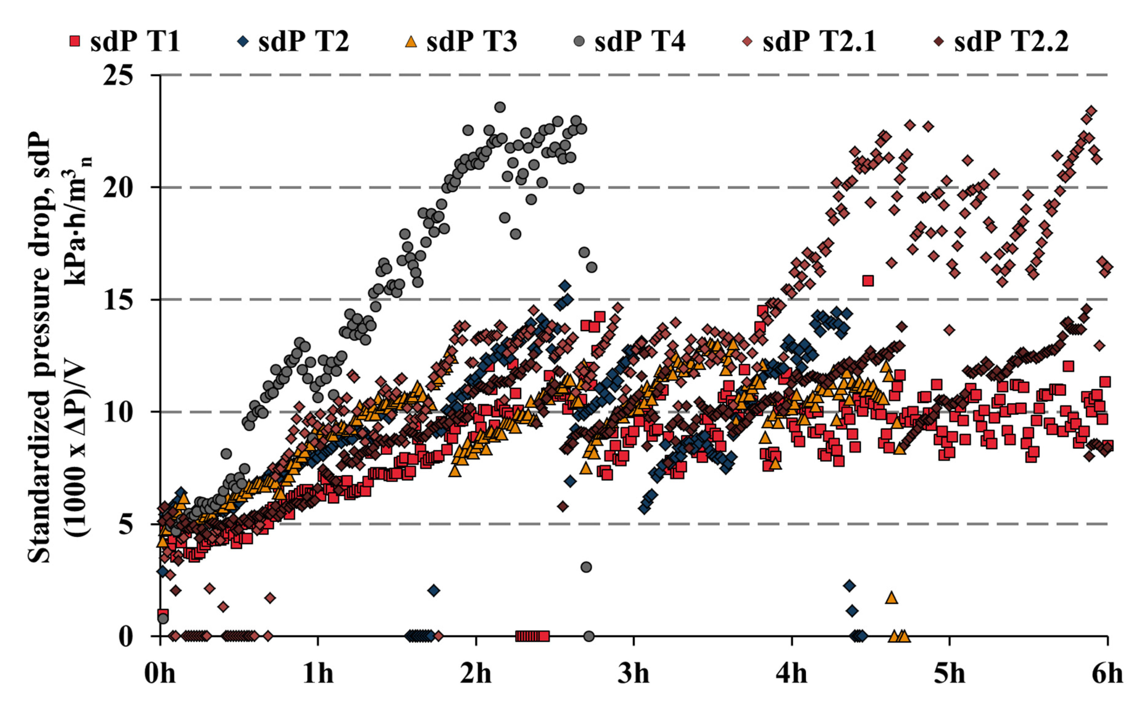
All filtration tests were carried out at filtration temperature equal to 450 ± 5 °C and a constant stream of sorbents. Three of the tested sorbents gave the desired filtration/regeneration patterns. Thus, the sorbents fulfilled their basic requirement of keeping the filtration process stable. Only dolomite (T4) led to a complete failure of the filter. With dolomite, the filter cake resisted pulse cleaning and, thus, a constant rise in dP was measured.
Figure 3 presented below depicts the results of filtration data for all four sorbents. For tests 1–3, the time from the start until the first pulse cleaning (formation of filter cake layer), ranged from 1 h 45 min to 2 h 40 min. These values correspond well with the data previously collected. Moreover, the time between subsequent pulses was consistent and repeatable (from 40 min to 1 h 15 min) as can be seen during the analysis of the registered pressure drop vs. time patterns. The repetitive regeneration cycles indicate a stable operation of the filter. For T1, another interesting characteristic feature can also be noted. After the fourth hour of operation, the filter cake collected adopted a self-cleaning (without pulses) characteristic. This phenomenon was noted before, when the filter cake adopted a loose structure and linear velocities of syngas were sufficiently small. Furthermore, a well-selected particle size of sorbent and ratio of sorbent to char in the filter cake positively influenced the observed self-cleaning property. This phenomenon is rarely registered for filtration of gasification gases; however, it is quite conventional for the HT filtration of flue gases.
During T4, the severity of pulse jet cleaning was increased gradually in the search for any signs of improvement. An increase in pulse times from the conventional 200 ms to 500 ms and in the pressure of the pulses from 6 bar to 8 bar did not give any signs of cake recovery. Conversely, the severity of pulses led to some mechanical degradation of the filter elements, and pit holes at the dirty side of the filters were noted during the later inspection.
Concerning previous experience with CaO-based sorbents, dolomite should not have brought such a quick and decisive filter failure as noted for T4. At 60%, it is composed of CaO and flows well, similarly to chalk; thus, it is surprising to discover this problem. In the past, operation of the filter was tested for CaO precoating and co-filtration runs where the ratio of char to chalk was higher than 1:0.2 and stable filtration patterns were recorded. Noteworthy, the optimum point for operation of the filter with a pressure drop of 1 kPa was found to be the ratio of 1:1–1:2.
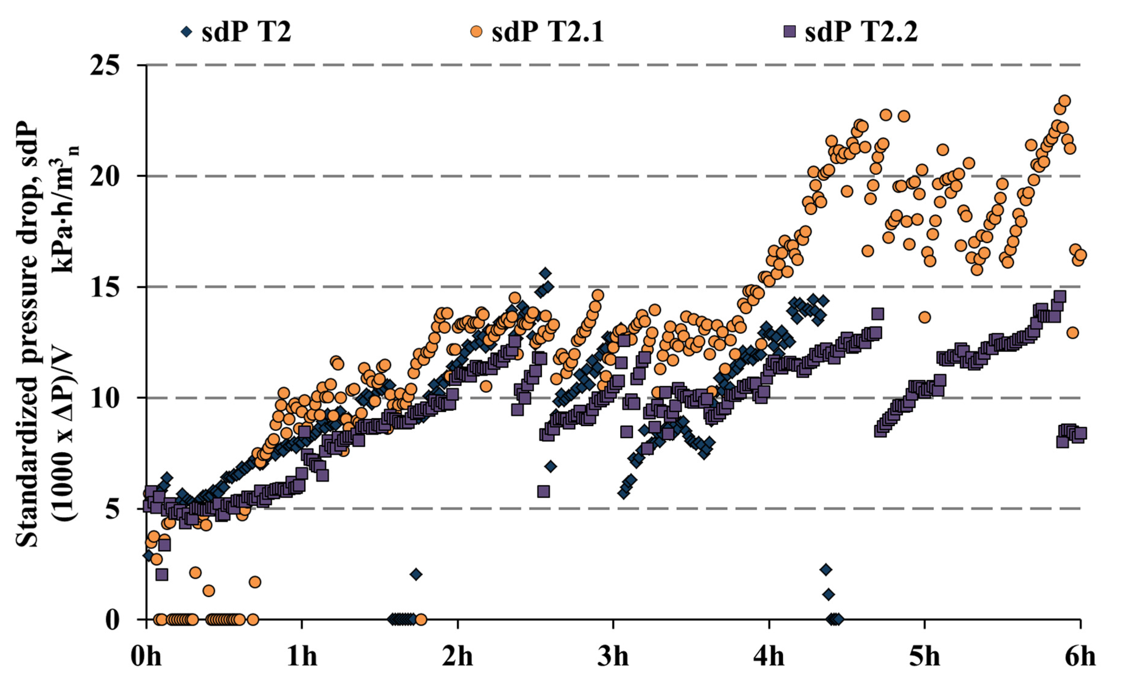
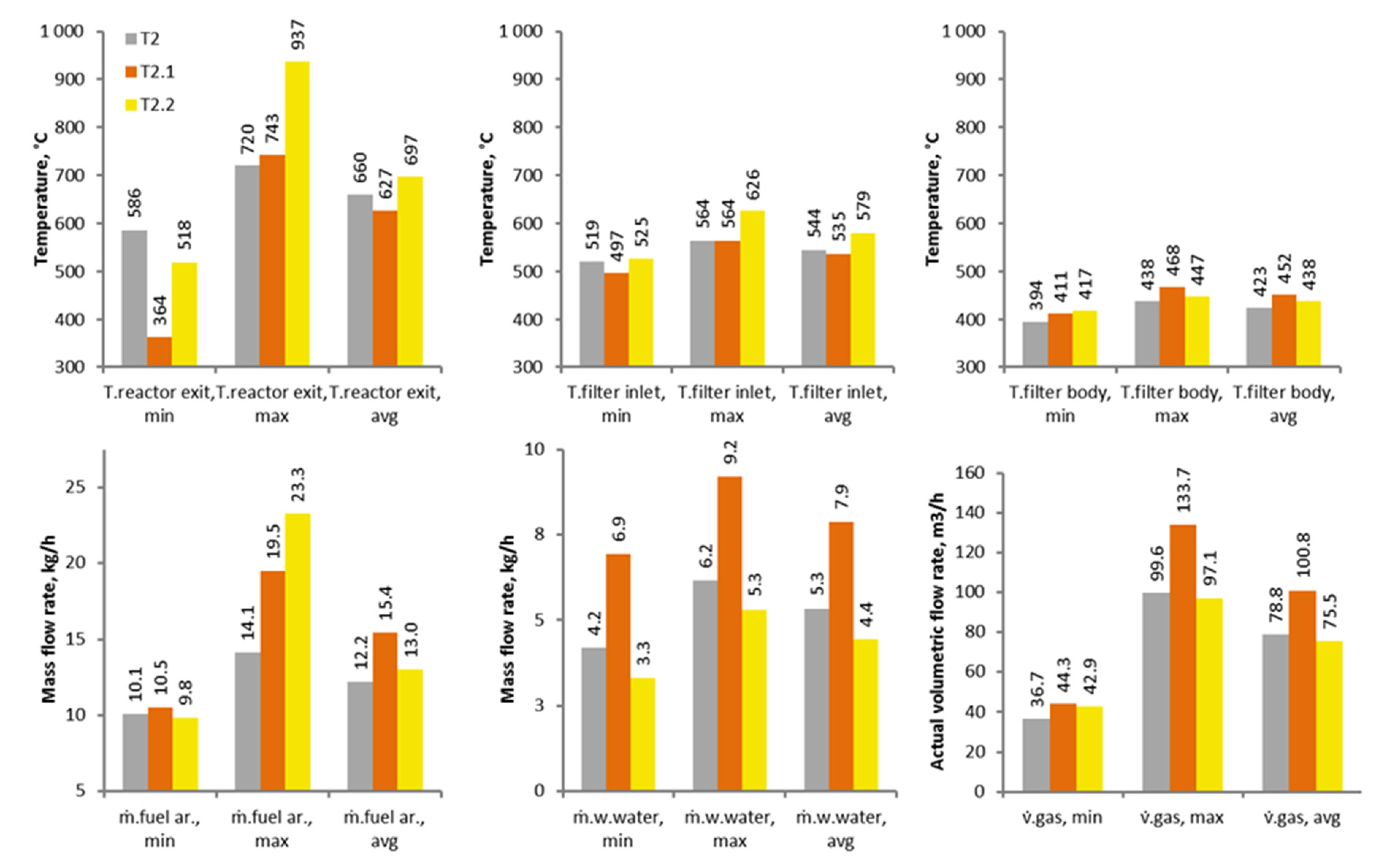
From preliminary testing, halloysite was shown to be a very promising material that enables both good gas cleaning and filter regeneration properties. For this reason, it was chosen for further experiments where limits of its filtration-enhancing properties were determined; thus, two additional tests were done (T2.1 and T2.2) where the mass stream of halloysite was kept constant and gasification conditions were varied through the use of fuel with different moisture content. The changes in reactor operating conditions induced changes in the quality of produced syngas, which subsequently led to pronounced variations observed in the filtration process itself.
Analysis of the three halloysite experiments was primarily done with attention to temperatures of syngas at the reactor exit, at the filter inlet, and inside the dirty side of the filter. The data comparing the halloysite filtration tests are presented in
Figure 4 and
Figure 5.
As is often common for pilot installations, here, the operation of the reactor and the gas cleaning unit was also stabilized by trace heating. For the GazEla installation, the trace heating is mounted starting from the reactor outlet, throughout and past the HT filter. Due to the thermal mass of the filter, it has the most stable characteristic of temperature changes. The heating is primarily used for start-ups, as well as to keep the operation of the cleaning unit safe when an intermittent, unstable operation of the reactor happens. In normal operation of the pilot GazEla reactor, 550 °C to 650 °C syngas is produced at its outlet. The raw syngas temperature depends on reactor power and quality of the gasified fuel. As a standard, the filter body is kept at a minimum temperature of 430 °C.
For T2.1, the biomass was artificially wet to the point of 29 wt.%, while, for T2.2, the feedstock was dried to the point of 8.9 wt.%. The GazEla reactor was tested previously on biomasses of moisture content up to 40%; however, at this point, operation of the fixed bed changed dramatically, as did the tar content and characteristics of produced syngas. For the three experiments, the stream of fuel fed into the reactor (on a dry basis) was kept stable to simulate the conditions where the reactor power demand was kept constant and the quality of available fuel changed. This operational difference led to the variable stream of wastewaters condensed from syngas, as well as the stream of syngas calculated from the mass balance of the reactor. In a fixed bed, the instantaneous stream of fuel fed into the reactor cannot be measured directly with the precision known and needed for stable operation of FB gasifiers. Here, the changes in fuel stream were determined based on time-average mass balances and they were shown to be in good agreement with calculated mass and elemental balances.
In line with the above-mentioned findings, during T2.1, lower minimum and average temperatures of raw gas were noted at the reactor outlet. This stems from the higher demand for heat needed for evaporation of water contained in the feedstock. Thus, it may be counterintuitive that, during the same test, the temperature inside the filter body was on average 14–29 °C higher in comparison to the two other experiments. Such a characteristic was noted before for the GazEla reactor, where some residual oxygen was present in raw syngas. During the extended residence time in the HT filter body, and due to the high temperatures of the filters, the oxygen was consumed in exothermal reactions. Such phenomena are predominant for fixed-bed gasification of feedstocks with very high moisture content, and they are also often connected with the production of very high amounts of heavy tars. The reason for this is that the temperature of the pyrolysis zone in a fixed-bed reactor drops and shifts toward the production of higher-molecular-weight tars (lower thermal breakdown of the tars). The heavy tars are difficult to measure analytically as they are very reactive and easily convert to polyaromatic hydrocarbons (PAH). The PAHs in tar can then undergo spontaneous polymerization, as a result of the high availability of C–O–H bonds, e.g. in phenols, or they can polymerize/carbonize and form solid-state char. These changes in the chemistry of tars are also one of the main reasons why HT filters often lose their porosity and eventually increase their baseline dP. To support this notion, the authors hold experience gathered throughout the past five years of operation of the filter, whereby a situation never occurred where the filtration of post-combustion gases (flue gases) led to a complete failure of the filter elements (pressure drop exceeding 6kPa), despite the great range of tested operational parameters. In flue gases, the stable filtration behavior is adopted much more quickly, mostly during the first 1–2 h, and it is possible to cycle between operational baseline set points without problems. The filter also operates on flue gases at much higher temperatures without instability. Supporting this thesis seems also to be the experiences from entrained flow, membrane reactors, where completely tar-free syngas is produced, e.g., utilized in integrated gasification combined cycle power plants. There also, the syngas ceramic filters are commonly operated close to their upper temperature limits of 900–1000 °C with acceptably long maintenance cycles (>5000 h).
In
Figure 5, it can be seen that, in T2.1, the filtration behavior adopted two separate patterns. In the first part of the tests, the pressure drop increased steadily, up to the set point of baseline dP (<2.5 h). At this time, regeneration pulses occurred every ca. 4–5 min, which was never observed for continuous stable runs, indicating that the filter cake kept sticking to the surface of the filters. To keep the unit in operation, the pressure drop set point was not changed until ca. the fourth hour of the test. From previous experience, a stable filtration pattern can be recovered for some cases where the thickness of the filter cake layer is deliberately, substantially increased. A thicker layer of filter cake tends to drop off the elements in larger flakes; however, this can also lead to patchy cleaning and irreversibly higher operational baseline of the filter. In this case, the method was successful, and, after the fifth hour, the time intervals between pulses started to increase. This can be observed by the dropping slopes of the dP curve between subsequent regeneration cycles. In stable filtration runs noted for both T2 and T2.2, the duration between regeneration pulses reached the conventional 1 h to 1 h 15 min.
Neither the temperature at the filter inlet nor the temperature in the filter body seemed to have any correlation with the moment when the filtration started to run stably. The moment when the filtration stabilized for T2.1 was in good relation to the time when the temperature profile of the pyrolysis zone of the reactor reached 500 °C. No noticeable change in the composition of syngas with respect to permanent gases (O2, CO2, CO, CH4, H2), the stream of fed fuel, or stream of recovered wastewater was registered. Thus, the three performed tests indicate the predominant role of tars in keeping the syngas filtration stable. Noteworthy for T2.1 was also the much higher actual stream of syngas filtered. The higher amount of water in raw syngas led to an increase in the filtration velocity, Uf (linear velocity of gas passing through a filter element, m/s). For HT applications, a commonly accepted value of maximum allowable Uf is 3 m/s. However, from experience, the filtration of syngases from fixed-bed reactors at Uf > 1.5 m/s cannot be kept with a pressure drop lower than 2kPa. Hence, to keep the dP low, the operational optimum was found for this unit to keep the Uf in the range from 1 m/s to 2 m/s. During T2.1, the Uf reached the maximum of 1.9 m/s.
5.2. Water, Tar, and Solid Particle Content
The water content of syngas at the outlet from the gasifier is directly connected to fuel composition, its moisture content, and the amount of steam used as a gasifying agent. Secondary reactions connected to hydrogen present in fuel further lead to the formation of steam, which can take part in tertiary reforming reactions. For the GazEla reactor, a fuel of moisture content 25 wt.%. was found to be optimal. The moisture content of the fuel and the amount of steam added for temperature control of the reactor’s bed together have a high influence on the amount of tar produced. For the pilot-scale GazEla reactor, the content of organics in raw syngas can reach up to 50 g/Nm
3 for waste fuels such as sewage sludge. For the majority of conventional feedstocks, the value does not exceed 25 g/Nm
3.
Table 4 presents concentrations of the basic contaminants in raw syngas (at reactor outlet) and after passing through the HT filter. For all tested points, one prevalent observation can be reported. Both water and tar contents were slightly reduced in the HT filter, even though the filter was operated at a moderate temperature of 450 °C and the filters were constructed from theoretically chemically non-active Al/Si material composites. For chalk, halloysite, kaolinite, and dolomite, the values of tar reduction were equal to 18.2%, 10.3%, 10.4%, and 16.9%, respectively. Thus, the CaO-based sorbent may give the best tar reforming characteristics while AlO–SiO materials take part in tar reforming to a lesser extent (halloysite, kaolinite). MgO is also known to participate in tar reforming in FB reactors; however, here, dolomite performed slightly worse than clean chalk. From current experience, it is hard to determine to what extent this effect is connected to the action of the sorbents themselves, because tar reforming on HT filters operated without sorbents (char alone) was also noted previously. It is noteworthy to say that most ceramic filters are built of mullite or other aluminosilicates and, thus, in their chemical composition, show similarities to halloysite and kaolinite. Thus, it was proposed that the reduction of tar content in the filter vessel may originate from a combination of basic thermal decomposition of high-molecular-weight tars or their polymerization and phase change to soot as a result of long residence time, which may be catalyzed by the presence of Ca, Mg, Al, and Si.
In the analysis of particulate matter content of syngas, there is always great uncertainty connected with the determination of solids entrained from fixed-bed reactors. This subject is connected with technical limitations in the size of sampling probes, as well as the size distribution of particles entrained from a fixed bed of the reactor. For this reason, the particulate matter (PM) presented in
Table 4 was only determined through the gas sampling of syngas downstream of the ceramic filter. The amount of PM in syngas upstream of HT filter was calculated through a mass balance of C and ash present in recovered filter cake. For T1, T2, and T4, no PM was measured downstream of the filter. Only for T3 was a small amount of PM registered at the outlet from the filter, indicating a breakthrough of dust which can happen if the layer of filter cake after pulse cleaning is too thin. Previously, another source of PM in syngas filtered on ceramic elements was also found. In HT dry gas cleaning systems, where the installation is subjected to large quantities of tars and does not operate continuously (the pilot system is a research installation), small amounts of polymerized carbon deposits can form at cold spots of the ceramic filter and pipelines where the temperature of syngas is not sufficiently high to keep condensation of high-molecular-mass tars from occurring. At such places, tars tend to condense and polymerize, thus creating deposits of very brittle carbon structures. However, this problem was never noted at installations where tars originate from FB reactors, because these tars are of much different composition (mostly light tars), and the concentrations of gravimetric tars rarely exceed 15 g/Nm
3.
Proximate and ultimate analysis of chars recovered from the ceramic filter unit was done to assess the ratio of char entrained from the reactor in relation to the stream of fed sorbent (
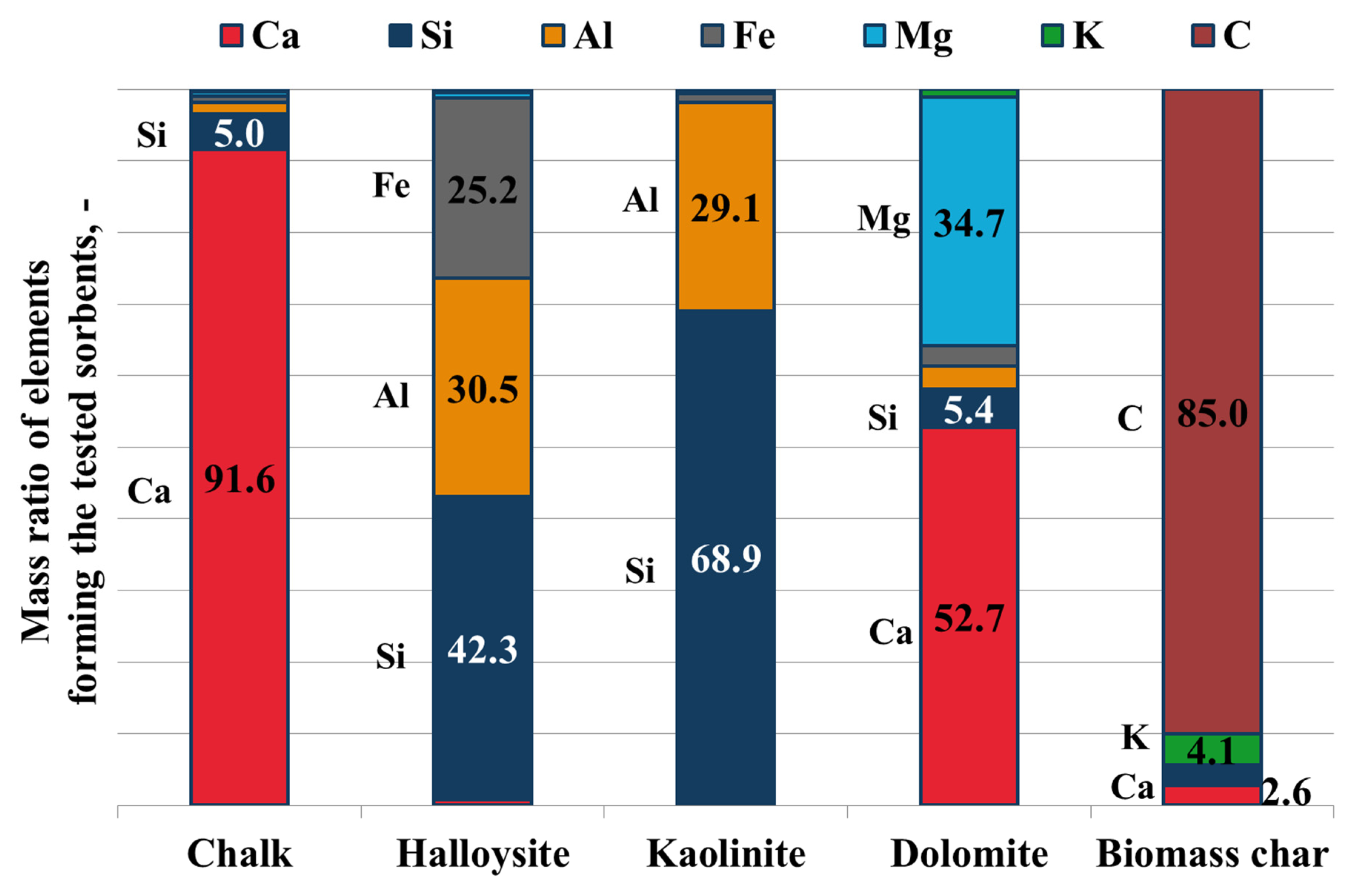
Table 5). For T1 and T4, the ratio of sorbent to char in gas was similar as can be seen from the proximate and ultimate analysis of the filter cakes. Similarly, T2 and T3 had similar char-to-sorbent ratios. Filter cakes from T1 and T4 were much richer in C and showed much smaller amounts of ash. Regarding the filter cake obtained from the reference test, the sample was a mixture of biomass char and ash with high C, A, and Cl contents. It can also be seen that the ratio of char to the sorbent for T1–T4 was equal to 1:0.9; 1:4.2; 1:5.0, and 1:1.25, respectively.
Subsequently, qualitative and quantitative analyses of AAEMs present in filter cake samples were performed, and
Table 6 collates the results. Values presented in parentheses in each cell correspond to a given content of the ash species in the fresh sorbent. The last column of the table is fitted with data from the analysis of clean char from the gasification process of wood chips where no co-filtering agent or sorbent was used. Based on this comparison, the analysis of changes in ash chemistry was possible, giving grounds for raising conclusions as to which AAEMs are volatilized during gasification in the GazEla reactor and can be captured from syngas with the use of the filtration/sorption method.
It is visible that, for all test points, dilution effects of the sorbents with ashes from biomass took place. Thus, with the use of the mixing law, it was checked whether there were any high deviations from the mixing proportions of ashes obtained from the sorbents and biomass chars. Such findings can indicate the capture of species volatilized in a reactor, as well as volatilization from the filter cake, thus indicating lower efficiency for its removal.
To some extent, chars from different tests interact with each other and are extracted together from the filter vessel even after prior cleaning of the elements and their precoating with another sorbent. Thus, for T1 and T4, it can be seen that the sorbents used were rich in Ca and Ca–Mg, respectively. Sorbents applied in T2 and T3 had similar chemical compositions (rich in Al and Si); however, halloysite is also naturally rich in Fe. It can be seen here that the sample from T2 (halloysite) was partially polluted with chalk from T1, whereas samples from T4 (dolomite) contained some kaolinite from T3. It is interesting that halloysite, which contains high quantities of Fe, did not contaminate the sample from T3. This finding may be partially supported by the observed good filtration-enhancing properties and flowability of halloysite. Noteworthy also, even though the amount of ashes in biomass was small and, thus, the dominance of compounds originated from sorbents was very high (ratio of ashes 1:10–1:50) for all samples, the effect of ash enrichment in constituents characteristic for biomass ashes such as K and Na was high.
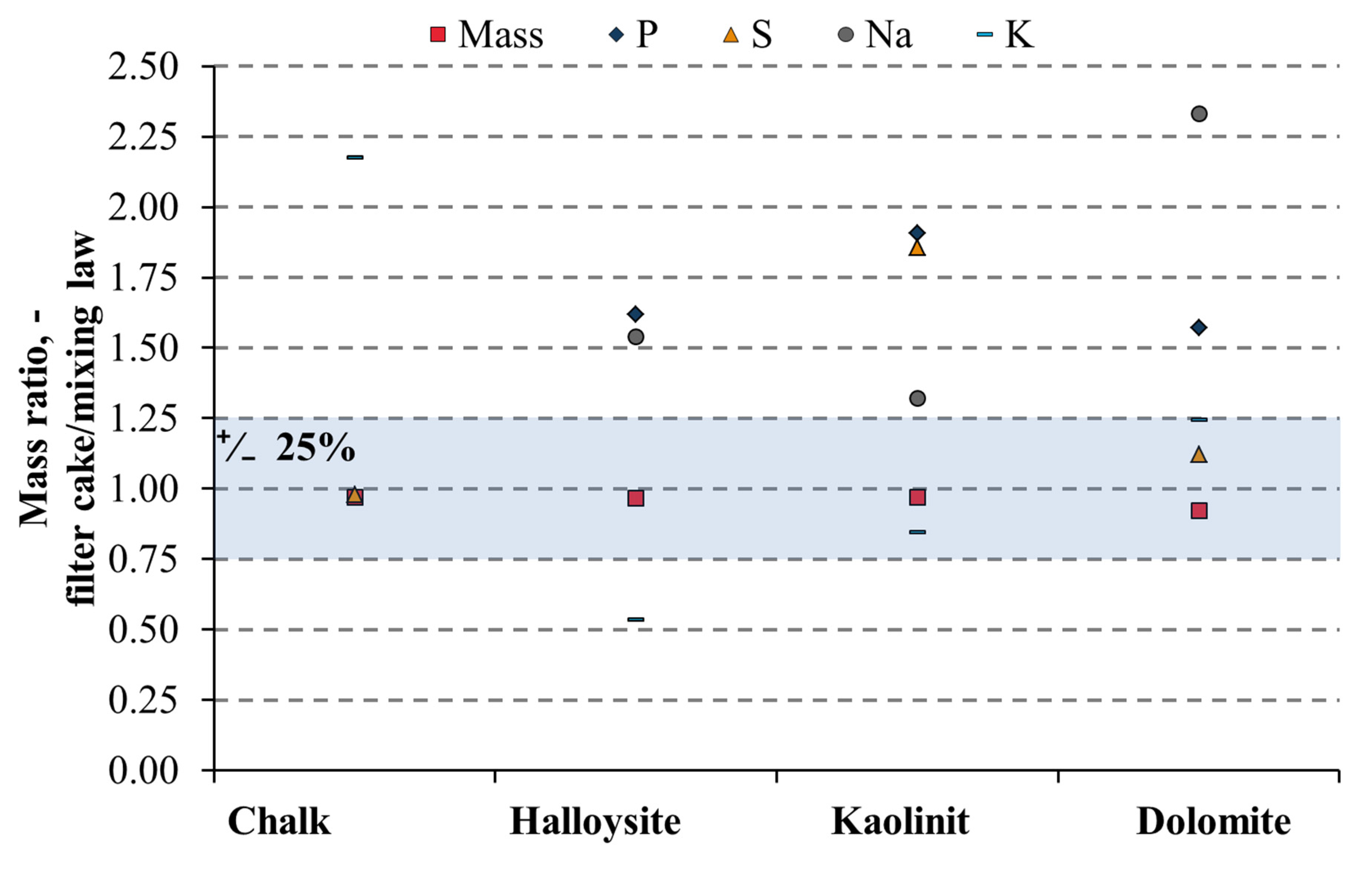
For a more visual comparison of the results,
Figure 6 was prepared where samples were compared through mass balance analysis, and the results are presented as ratios of species calculated from the mass balance related to the concentrations measured in samples. Thus, values above 1 indicate here that the content of the specie in the filter cake was lower than expected from the mixing law and may indicate lower removal efficiency of the element. On the other hand, values below 1 indicate that the content of an element in the filter cake was higher than predicted and, thus, may indicate its preferential removal from syngas. Results fitting into a range of ±25% are generally accepted to be in agreement with the mixing law. The streams of char and sorbents were all in good agreement, and the ratios of values calculated ranged from 0.92–0.97.
The best correlation with the mixing law was found for dolomite, where only concentrations of P and Na in filter cake were well below half of the expected value, which may indicate lower retention in the filtration/sorption system. At the other end of the scale was chalk, which was found to be in good agreement only for S, while lower than expected contents of K (2.17), Na (5.17), and P (8.19) were noted (P and Na values are off the scale presented in
Figure 6).
For halloysite, K was the only measured element which might indicate preferential adsorption (0.53) from syngas. For all sorbents, the scatter of the results indicates that it is very difficult to close mass balances of elements in fixed-bed gasification systems. Primarily for halloysite, S concentration in the filter cake was more than 20 times lower than the mass balance indicates (off the scale in
Figure 6). On the other hand, for dolomite, the Na content in filter cake was equal to less than 4.5 times the prediction. For future work, it is, thus, advised to try applying other analytical procedures in the search for these elements in syngas; however, as already mentioned, ion chromatography of gas sampled through absorption in NaOH does not provide as clear results as hoped for.
The difficulty in closing mass balances of elements in gasification systems can be seen here. A sampling of char from syngas in the real installation is only possible for a test designed specifically to be done without the use of sorbents. Even though the biomass source was kept constant during the research, its exact composition, as well as its gasification conditions, varied. Taking into account that components of biomass ash volatilize in a manner related to their ash composition and process parameters, the char bed does not remain constant nor does its ability to readsorb AAEMs from raw syngas.
5.3. Heavy Metals
The starting assumption for the determination of collection efficiency of heavy metals is that, in process conditions of the filter, the species that contain them are attached to other solids present in the gas. When subjected to filtering, they should be recovered either directly through filtration (mechanical separation) or indirectly by adsorbing onto the surface of filter cake particles, as they already have a well-developed surface and the HT filter conditions are more favorable for adsorption than those that occur in the reactor.
Table 7 collates the obtained results regarding the amount of heavy metals present in fresh sorbents, as well as in filter cakes recovered after the filtration/sorption process. Values presented in parentheses in each cell correspond to the given species content of the fresh sorbent.
In the case of five elements, a 10-fold increase in concentration was registered in comparison to the result of the fresh sorbent. These elements were Cr, Mn, Mo, Ni, and Zn. In the case of Zn and Mo, an increase in concentration in all samples of filter cakes was noted. For Zn, the highest gain was noted in T3 (25-fold for kaolinite), while the lowest was noted in T4 (six-fold for dolomite). Previous studies on the volatilization of metal compounds during the thermochemical treatment of ashes concur with this finding [
12,
13,
14]. For Mo, higher recovery was noted in T1 (17-fold for chalk), while the lowest was noted for both T2 and T3 (two-fold for halloysite and kaolinite). For Cr, a higher increase in concentration was noted in the case of T1 (25-fold for chalk), while the lowest was noted for T3 (two-fold kaolinite). For Mn, T4 gave the highest increase in concentration (840-fold for dolomite), while the lowest was noted for T3 (3.6-fold for kaolinite). The increase in the amount on Mn in the T4 filter cake was substantial, and the determination of its origin needs further investigation. For Ni, the highest rise in concentration was noted for T1 (23-fold for chalk), whilst the lowest was noted for T3 (3.5-fold for kaolinite).
Thus, all sorbents showed the concentration of heavy metals in their relevant filter cakes higher than expected from mass balances. During the research, there was no method for the determination of any residual heavy metals in syngas downstream of the ceramic filter that could support any definitive conclusions on any preferential removal of heavy metals.
5.4. Halides and H2S
Generally, it is known that K almost exclusively volatilizes with correlation to Cl. Thus, from the results presented above, it was expected that the Cl content in syngas should be low. For baseline conditions, the amount of HCl measured in syngas was close to the detection limit of the method. In raw syngas, the mean value of HCl present was equal to 5 ppm
v. To assess its removal in the gas cleaning system, the analysis of Cl content in side-products was necessary. No F or Br content in the gas was detected.
Table 8 presented below depicts all results collected regarding Cl content in condensates from gas cooling. It can be seen here that, in syngas after treatment with kaolinite and dolomite, Cl concentration was so low that it reached the lower detection limit of the method.
For filter cakes, the results of Cl content are presented in
Table 5. The results indicate that biomass char contained 16.9-fold higher Cl concentration than the biomass before thermochemical treatment, which supports the theory of Cl readsorption on the bed of char or its preference to remain in the concentrated solid phase composed of ash and char.
During balancing of Cl present in the system, it was noted that only up to 30 wt.% can be accounted for with all the measured inputs and outputs. The remaining stream of Cl presumably stayed in reactor bottom ash, as known from the literature [
3,
16]. However, due to technical limitations of the lab-scale conditions and the insufficient amount of bottom ash generated from clean biomass like wood chips, it was not possible to adequately sample and analyze this stream.
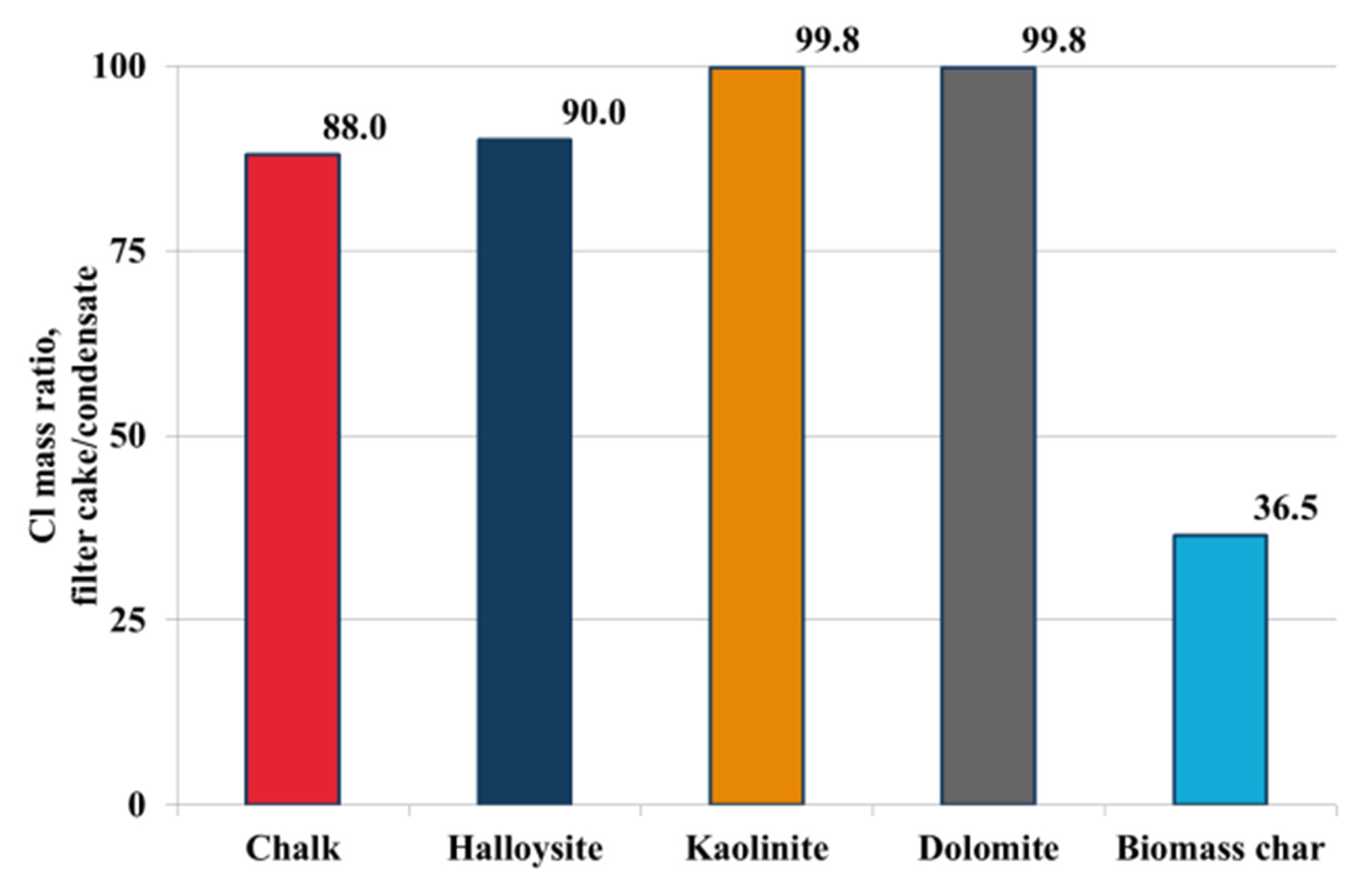
Performed analyses allowed determining the amount of HCl present in raw syngas, whereas no HCl could be measured after the last step of gas cleaning. To summarize its removal,
Figure 7was prepared. The figure relates the actual streams of HCl trapped in filter cake to Cl content in condensate from syngas cooling. For T1 and T2, 90% of Cl present in syngas was recovered in the filtration/adsorption step. This value should be compared with Cl content measured for the reference case, where filtration was carried out without any sorbent and Cl was preferentially recovered in the condensate from syngas cooling.
Finally, during ion chromatography of the liquid samples, the detection of H2S was also expected. However, for all tested samples, no S ions were detected. This result indicates that the applied analytical procedure needs to be further developed in the future to give better precision in the determination of syngas composition.
6. Conclusions
To summarize, during the research, the use of four sorbents of distinctive chemical and physical properties was tested for HT conditioning of syngas, namely, chalk (CaO), dolomite (CaO–MgO), halloysite (AlO–SiO), and kaolinite (AlO–SiO). The two representative aluminosilicates differed from each other in their tertiary structure.
The research showed that co-filtration of dolomite with solids from the gasification process may inversely affect the regeneration of HT filters but lead to quick and irreversible filter failure. Even though the sorbent itself is easily flowable, is easy to handle, effectively pre-coats the filters, and gives good sorption parameters, it is also the first material on the list of tested sorbents which cannot be reported to have filtration-enhancing properties until further research on merits of its application is available.
For the rest of the tested sorbents, design criteria regarding both pulse-back regeneration of the filter and sorption of syngas were satisfied. Collected data allowed concluding that the concept for one-vessel multicomponent gas cleaning is possible and can be successful.
All tested materials adsorbed 90%–99% of Cl present in raw syngas, thus reducing its content to levels below 5 ppmv, which, for most energetic applications, is considered as acceptable.
HT filtration and sorption provides a means for the reduction of high-molecular-weight tar content in the range of 10% to 18%, depending on the sorbent used. From preliminary results, it was found that CaO- and CaO–MgO-based materials have higher tar reforming capabilities.
In pilot-scale gasification process conditions, no direct sign of preferential removal of AAEMs on the filter cake-containing sorbents was found. Char in the fixed bed acts as the first stage adsorber and causes retention of compounds volatilized from ash, leading to the high variability of the obtained results.
After filtration on precoated ceramic filters, no presence of PM could be measured in the pilot-scale gasification installation. The only source of solids determined in gas after filtration originated from a temporary breakthrough of particles after pulse-back cleaning or marginal condensation and polymerization of heavy tars.
The application of high-efficiency, HT filter for dedusting of syngas was proven to be the preferred technology for the first step of syngas cleaning. Dust-free syngas allows for its direct cooling and condensation of organic matter, as well as cleaning in oil scrubbers or its further upgrading without problems related to fouling of the installation. In syngas cleaning, however, it is vital to remove tars as quickly as possible and accordingly to their condensation temperature. The fouling of heat exchangers in dust-free syngas conditions follows the path of condensation of heavy tars on contact with “cold tubes” of the heat exchanger and further polymerization of the liquefied tars. A solution to this problem was found in all applications where syngas cooling is either more rapid and goes down to temperatures below the water dew point or does not cool syngas down to levels where heavy tars can condense.
Furthermore, detection of H2S was expected during ion chromatography of the condensed phase of syngas, as well as from the dedicated sampling of syngas through NaOH absorption. However, for all tested samples, no S ions were measured. This result indicates that the applied analytical procedure needs to be further developed in the future to give better precision in the determination of syngas composition.
Finally, from the analysis of obtained data, halloysite was shown to give the best overall performance in syngas cleaning through sorption-enhanced HT filtration. It had superior filtration and pulse-back cleaning properties, and it remained flowable in all apparatuses used for its storage, handling, and feeding. For very high filtration velocity (1.9 m/s) and syngas of high water and heavy tar content, it allowed the filtration to remain stable even though the set point of dP had to be increased to 2 kPa. In terms of gas cleaning properties, CaO remains the best solution because of its higher tar reforming properties and the comparable ability for the removal of Cl.


