Article

Configuration Optimization and Performance Comparison of STHX-DDB and STHX-SB by A Multi-Objective Genetic Algorithm

1
School of Power and Energy, Northwestern Polytechnical University, Xi’an 710129, China
2
School of Mechanical Engineering, Northwestern Polytechnical University, Xi’an 710072, China
*
Author to whom correspondence should be addressed.
Energies 2019, 12(9), 1794; https://doi.org/10.3390/en12091794
Submission received: 16 March 2019 / Revised: 17 April 2019 / Accepted: 7 May 2019 / Published: 11 May 2019
(This article belongs to the Special Issue Heat Exchangers for Waste Heat Recovery)

Abstract

:
Based on the thermohydraulic calculation model verified in this study and Non-dominated Sorted Genetic Algorithm-II (NSGA-II), a multi-objective configuration optimization method is proposed, and the performances of shell-and-tube heat exchanger with disc-and-doughnut baffles (STHX-DDB) and shell-and-tube heat exchanger with segmental baffles (STHX-SB) are compared after optimization. The results show that, except in the high range of heat transfer capacity of 16.5–17 kW, the thermohydraulic performance of STHX-DDB is better. Tube bundle diameter, inside tube bundle diameter, number of baffles of STHX-DDB and tube bundle diameter, baffle cut, number of baffles of STHX-SB are chosen as design parameters, and heat transfer capacity maximization and shell-side pressure drop minimization are considered as common optimization objectives. Three optimal configurations are obtained for STHX-DDB and another three are obtained for STHX-SB. The optimal results show that all the six selected optimal configurations are better than the original configurations. For STHX-DDB and STHX-SB, compared with the original configurations, the heat transfer capacity of optimal configurations increases by 6.26% on average and 5.16%, respectively, while the shell-side pressure drop decreases by 44.33% and 19.16% on average, respectively. It indicates that the optimization method is valid and feasible and can provide a significant reference for shell-and-tube heat exchanger design.

1. Introduction

Shell-and-tube heat exchanger (STHX) is one kind of mechanical device that can exchange heat through a tube wall between two fluids of different temperatures, which are widely used in oil cooling in aero-engines, heating, chemical and food industries, and so on [1]. In the process of heat exchanger design, different configuration parameters can lead to different performances. In order to obtain the better performances, heat exchanger optimization is increasing significantly [2].
In the pursuit of optimized designs, configuration optimization as well as optimization methods application have been analyzed from different points of view. The genetic simulated annealing algorithm [3], biogeography-based algorithm [4], firefly algorithm [5], Jaya algorithm [6] and differential evolution algorithm [7] were used to minimize the cost of the heat exchanger. However, in the actual design process of the heat exchanger, total cost minimization is not the only objective. Many other objectives need to be considered, just like heat transfer capacity maximization, pressure drop minimization, and so on. Thus, the results of research that can consider more than one objective simultaneously could be more meaningful.
In the research of Sanaye et al. [8], the Bell-Delaware procedure and ε-NTU method were used to calculate the shell side heat transfer coefficient and pressure drop of shell-and-tube heat exchanger with segmental baffles (STHX-SB), and the fast and elitist non-dominated sorted genetic algorithm was utilized to solve the optimization problem, which was to maximize the heat transfer coefficient and minimize pressure drop simultaneously, and obtain the Pareto optimal solutions. A method of a multi-objective genetic algorithm combined with numerical simulation was used by Wen et al. [9] and Wang et al. [10,11] to optimize the configuration of STHXs with helical baffles, and the Pareto optimal points of multi-objective optimization were obtained. In addition, this method was also used in the configuration optimization of a spiral-wound heat exchanger by Wang et al. [12]. Some novel theories were also used to design, calculate or optimize heat exchangers. Both Amidpour et al. [13] and Mirzaei et al. [14] applied the constructal theory combined with a genetic algorithm for STHX optimization. An optimization strategy that combined the entransy theory, numerical simulation and a genetic algorithm was proposed by Gu et al. [15] to minimize the entransy dissipation thermal resistance of STHX with helical baffles. Similarly, Chahartaghi et al. [16] used the entransy dissipation theory and Non-dominated Sorted Genetic Algorithm-II (NSGA-II) to minimize the entransy dissipation numbers separately caused by thermal conduction and fluid friction for STHX-SB. In addition, some other novel optimization algorithms were also proposed to optimize STHXs, just like the modified version of teaching-learning-based optimization [17], particle swarm optimization [18], Taguchi method [19], bat algorithm [20], and multi-objective heat transfer search algorithm [21]. In the investigation of Rao et al. [22], an artificial immune system is used with a generalized regression neural network to solve the optimization problem of heat transfer and overall pressure drop for a STHX-SB. Saldanha et al. [23] used Predator–Prey, Multi-objective Particle Swarm Optimization, and NSGA-II evolutionary algorithms to tackle the optimization problem of STHX and chose the best evolutionary algorithms by the Preference Ranking Organization Method for the Enrichment Evaluations decision-making method.
This research had successfully used theoretical approaches or numerical simulation to get the relationships between some configuration parameters and heat exchanger performances, and the corresponding configuration parameters were optimized based on some multi-objective optimization algorithms. Unfortunately, there was only one kind of heat exchanger optimized in each research, and the heat exchanger mentioned was not compared with some different kinds of heat exchangers which are commonly used. Thus, it is worth mentioning that Wang et al. [24] compared heat transfer and pressure drop performances among the STHXs separately with segmental baffles, continuous helical baffles and staggered baffles, and used the multi-objective optimization using a genetic algorithm to obtain the optimal Pareto front of STHX with staggered baffles. However, the comparison was only between the heat exchangers before optimization. The comparison of heat exchangers after optimization under the same condition could reveal their respective advantages and disadvantages after their corresponding configuration parameters were optimal.
In this paper, the configuration parameters of tube bundle diameter, inside tube bundle diameter, number of baffles of shell-and-tube heat exchanger with disc-and-doughnut baffles (STHX-DDB) and the configuration parameters of tube bundle diameter, baffle cut, number of baffles of STHX-SB are analyzed for heat transfer capacity and shell-side pressure drop based on thermohydraulic calculation of the Slipcevie method and Bell-Delaware method [25,26,27,28,29]. In addition, a multi-objective optimization method based on NSGA-II is utilized to optimize these two kinds of heat exchangers and compare the performances of them after optimization.

2. Physical Model and Thermohydraulic Calculation Model

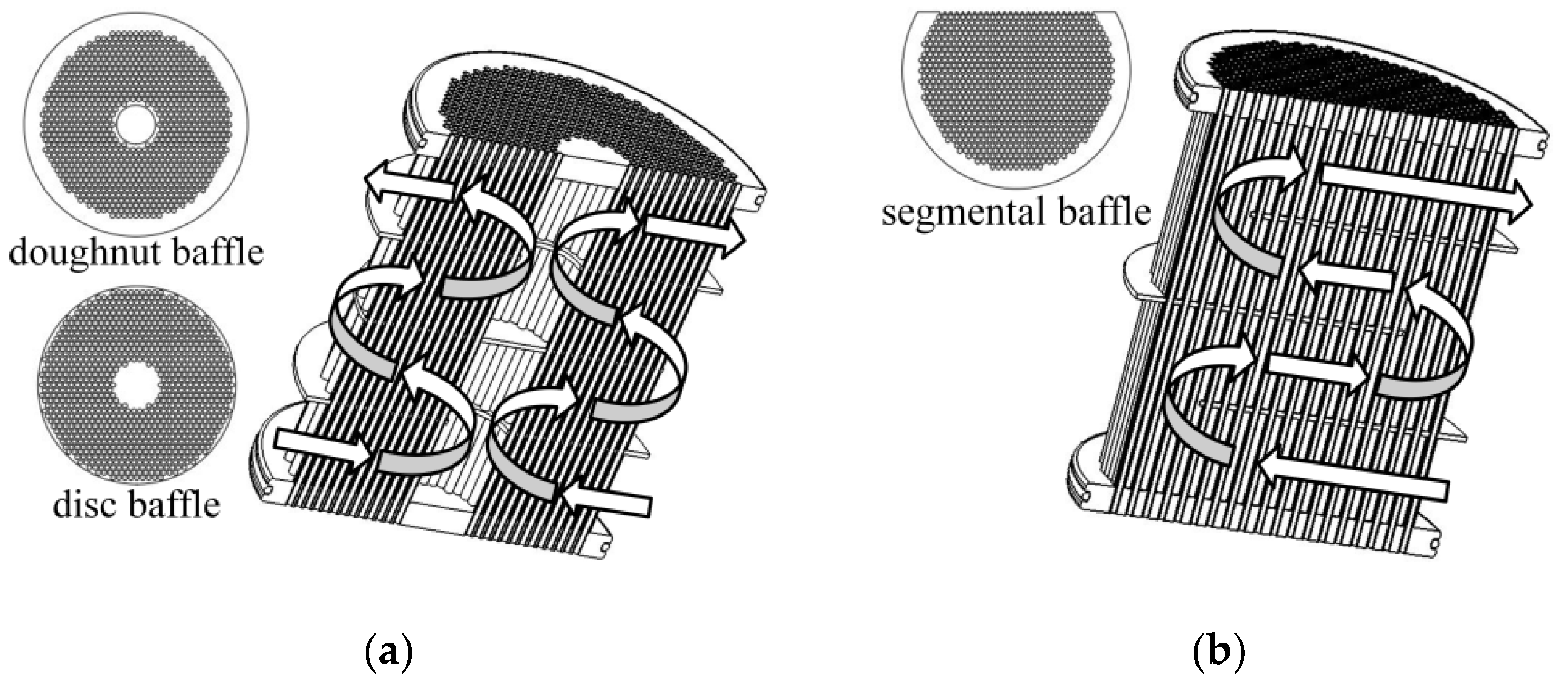
2.1. Physical Model and Configuration Parameters

Both STHX-DDB and STHX-SB primarily consist of heat transfer tubes, baffles, end plates, spacer tubes and shell. The spacer tubes are strung on four heat transfer tubes to locate the positions of baffles. All the baffles are uniformly distributed between two end plates. The differences between disc-and-doughnut baffles and segmental baffles result in the different fluid flow styles of shell-side between STHX-DDB and STHX-SB, as shown in Figure 1. The main configuration parameters of STHX-DDB and STHX-SB are shown in Table 1. The material of STHXs is an aluminium alloy.
To simplify calculations, assumptions are demonstrated as follows: (1) the leakages between baffles and tubes and those between baffles and shell are neglected; (2) the heat transfer between the fluid inside heat exchanger and the environment outside heat exchanger is neglected; (3) both the fluid of shell-side and tube-side are Newtonian and incompressible fluid with constant properties; and (4) the heat exchangers are new and there is no fouling.

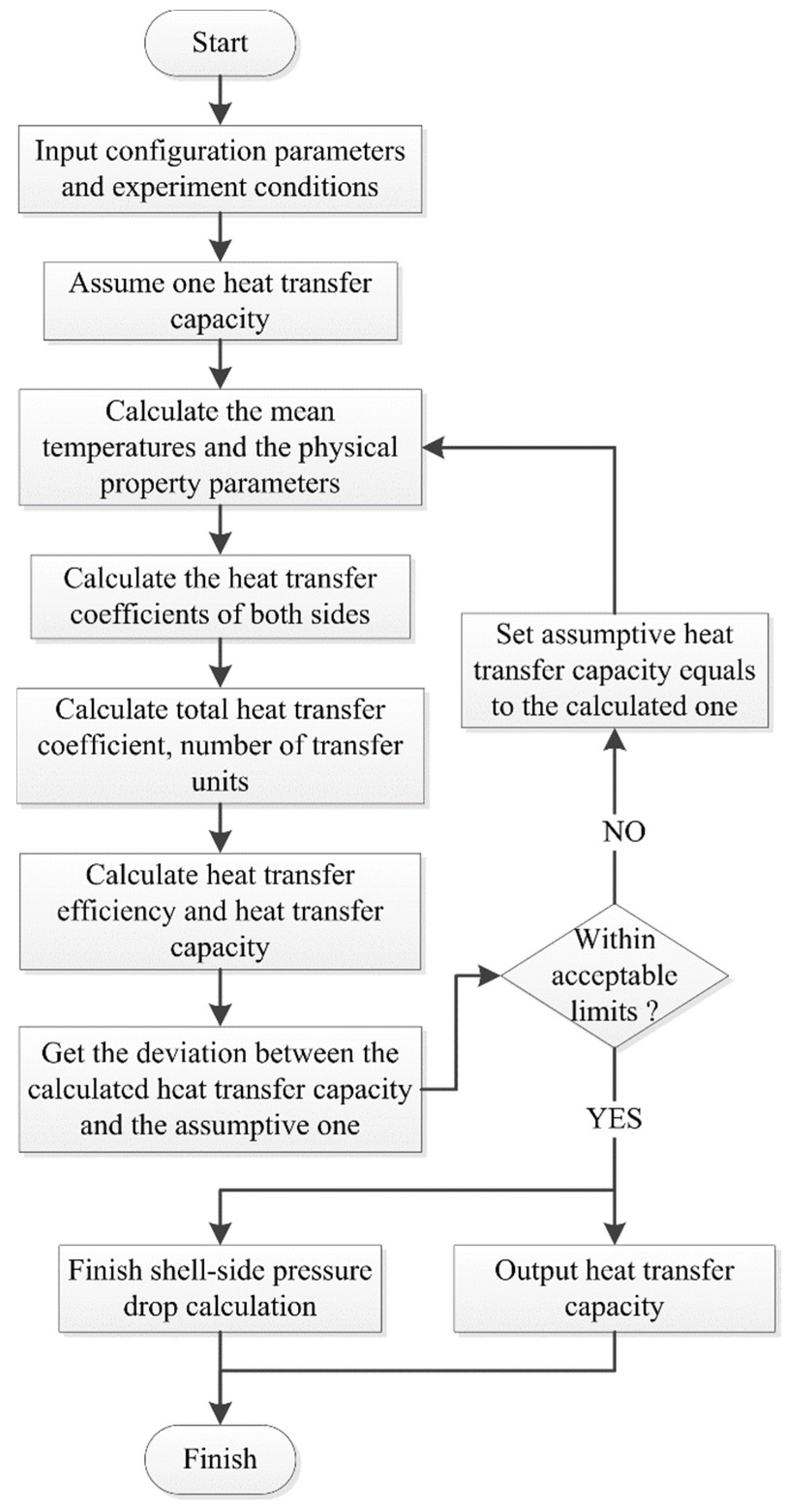
2.2. Thermohydraulic Calculation Model

Thermohydraulic calculation of STHXs includes heat transfer capacity calculation and shell-side pressure drop calculation. Basic formulas of heat transfer capacity calculation and shell-side pressure drop calculation are given in Appendix A and Appendix B, respectively. The main steps of this thermohydraulic calculation model are shown as follows:
  • Input configuration parameters of STHX as shown in Table 1, and input experiment conditions including inlet temperature/flow rate of tube/shell-side.
  • Assume one heat transfer capacity for STHX.
  • Calculate the mean temperature of tube wall, the physical property parameters (such as fluid density, kinematic viscosity, etc.) and mean temperature of shell/tube-side under the condition of the assumptive heat transfer capacity.
  • Calculate the heat transfer coefficients of shell-side and tube-side.
  • Calculate total heat transfer coefficient, number of transfer units, heat transfer efficiency and heat transfer capacity.
  • Set the assumptive heat transfer capacity equal to the calculated heat transfer capacity and go to step 3 until the deviation between the calculated heat transfer capacity and the assumptive heat transfer capacity is within acceptable limits.
  • Output heat transfer capacity and finish shell-side pressure drop calculation.
The flowchart of thermohydraulic calculation model is shown in Figure 2.

3. Optimization Method

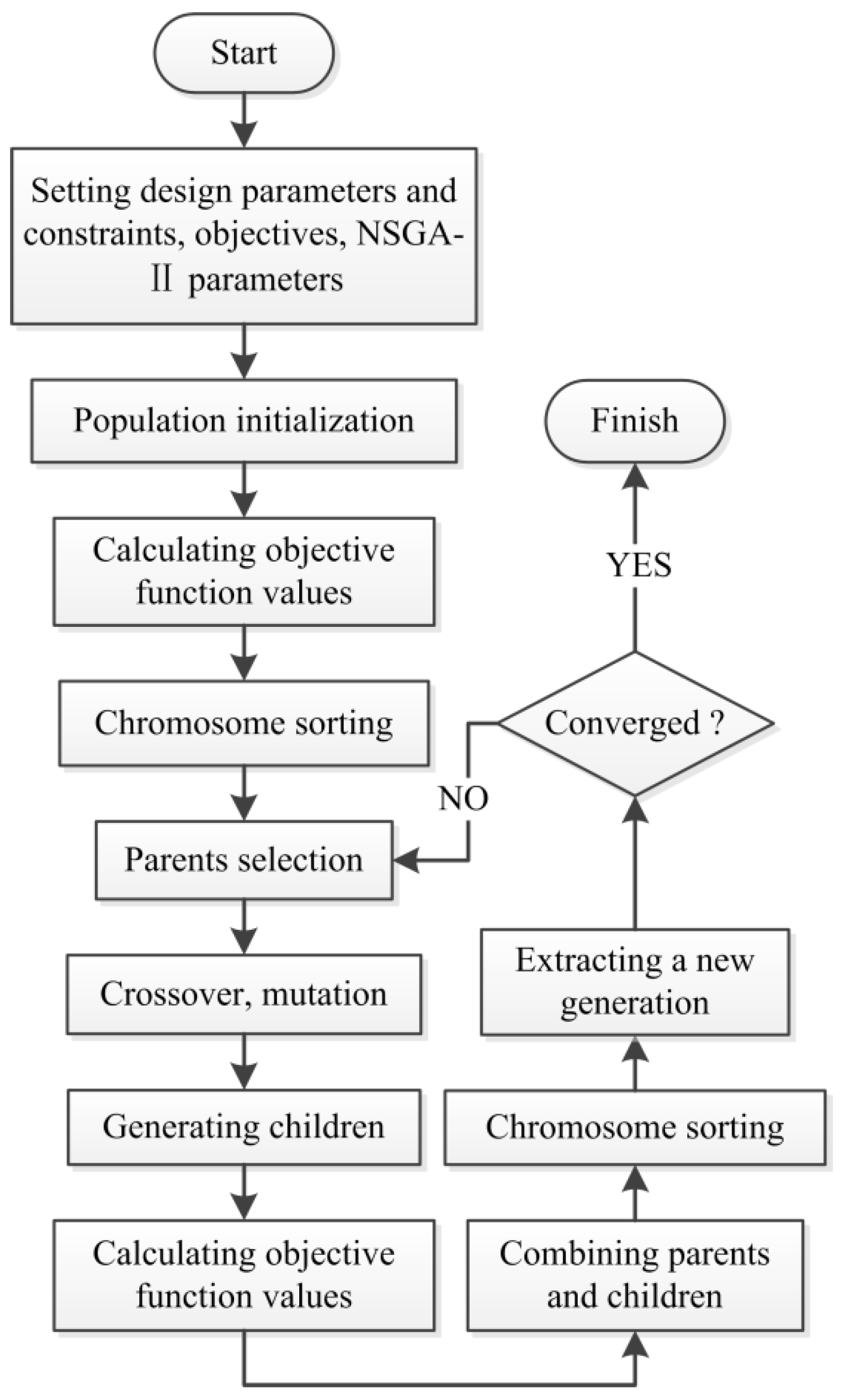
3.1. Multi-Objective Genetic Algorithm

It is quite difficult to get the absolute optimal solution of a multi-objective problem because of the conflict of objectives. However, a Pareto optimal front, which consists of a series of solutions, can be obtained through NSGA-II [30]. NSGA-II incorporates elitism [31], and any solution of the Pareto optimal front is generated at the price of other lower priority performances. The ranking scheme of this method adopts the non-dominated sorting method, which is faster than the traditional Pareto ranking method. The constraint handling method also uses a non-dominance principle as the objective, thus penalty functions and Lagrange multipliers are not needed, which guarantees that the feasible solutions are always ranked higher than the unfeasible solutions [32]. A genetic algorithm is a stochastic global searching probabilistic method, which emulates the genetic mechanism of Darwinian evolution and the process of natural selection. This method contains the main steps of selection, crossover and mutation and has the characteristics of self-adaptive, parallel, random [33].
The main steps of the optimization method are shown as follows:
  • Design parameters (such as tube bundle diameter, baffle cut, number of baffles, etc.) and constraints of them; optimization objectives (such as heat transfer capacity maximization, shell-side pressure drop minimization, etc.) are initialized.
  • NSGA-II parameters (such as population size, generation number, etc.) are initialized.
  • A random population is initialized based on population size, number and constrains of design parameters.
  • Calculate objective function values for each chromosome of the population.
  • Each chromosome is sorted based on non-domination and crowding distance. It should be noticed that the crowding distance is compared only if the rank for both chromosomes are the same.
  • The chromosomes suitable for reproduction are selected as parents of the next generation based on tournament algorithm.
  • Children are generated through crossover and mutation, and the objective function values of them are calculated.
  • Parents and children are combined, and each chromosome is sorted based on non-domination and crowding distance.
  • Extract the new generation based on ranking.
  • The above procedures are repeated from step 6 until the convergence.
Details of crossover and mutation are referred in [34]. The flowchart of the optimization method is shown in Figure 3.

3.2. Objective Functions and Design Parameters

In this case, in consideration of the thermohydraulic performances of STHX-DDB and STHX-SB, the heat transfer capacity Q and shell-side pressure drop ∆P are selected as objective functions. For STHX-DDB, tube bundle diameter Do, inside tube bundle diameter Di and number of baffles Nb are regarded as design parameters, and the multi-objective optimization problem can be formulated as Equation (1):
{ Min Q , Δ P S . t . 80   mm D o 113   mm 10   mm D i 70   mm N b = 2 , 3 , 4 , 5 , 6 .
For STHX-SB, tube bundle diameter Do, baffle cut P and number of baffles Nb are regarded as design parameters, and the multi-objective optimization problem can be formulated as Equation (2):
{ Min Q , Δ P S . t . 80   mm D o 113   mm 0.15 P 0.45 N b = 2 , 3 , 4 , 5 , 6 .
Except for the design parameters, the other configuration parameters of STHX-DDB and STHX-SB are shown in Table 1. The working conditions are shown in Table 2.

4. Results and Discussion

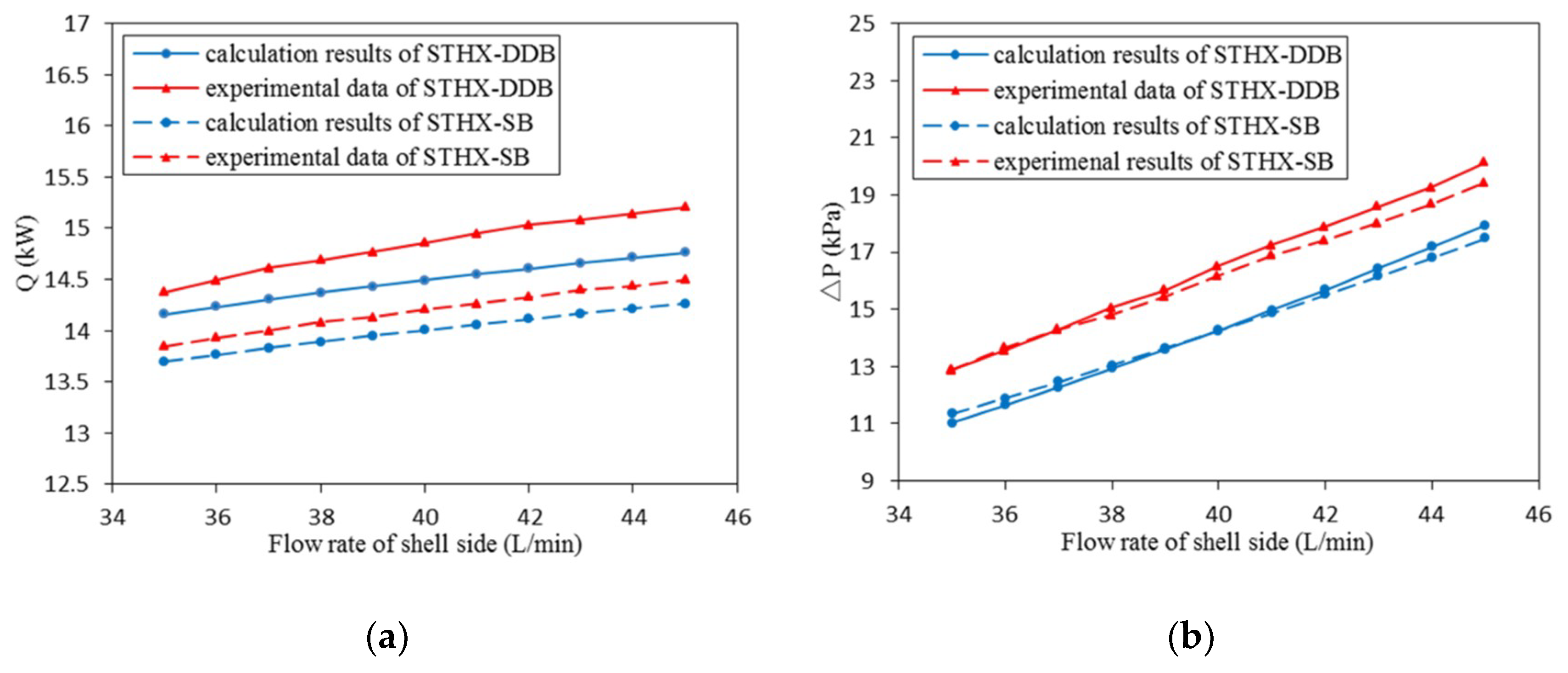
4.1. Model Validation

In order to validate the accuracy of thermohydraulic calculation model, calculation results are compared with experimental data. In this case, the tube-side fluids of these two heat exchangers, which are heated, are both fuel, and the shell-side fluids, which are cooled, are both oil. The experiment conditions and the testing equipment for STHX-DDB and STHX-SB are given in Table 2 and Figure 4, respectively, and the comparison results are shown in Figure 5.
The results illustrate that both the heat transfer capacity and the shell-side pressure drop obtained from calculation model are in agreement with the experimental results. The errors of the heat transfer capacity of STHX-DDB and STHX-SB are 1.5–3.0% and 1.1–1.7% with the average deviations of 2.4% and 1.4%, respectively, and those of shell-side pressure drop are 10.8–14.4% and 10.0–13.0% with the average deviations of 13.0% and 11.6%, respectively. Hence, it can be concluded that the thermohydraulic calculation model is reliable and the errors are acceptable. The differences may be caused by simplification of physical model, deviation of formula itself, and unavoidable measurement error in experiment.

4.2. Design Parameters Effects of STHX-DDB

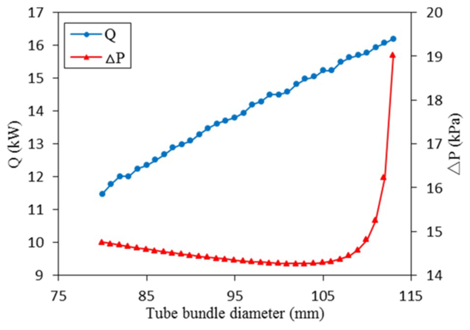
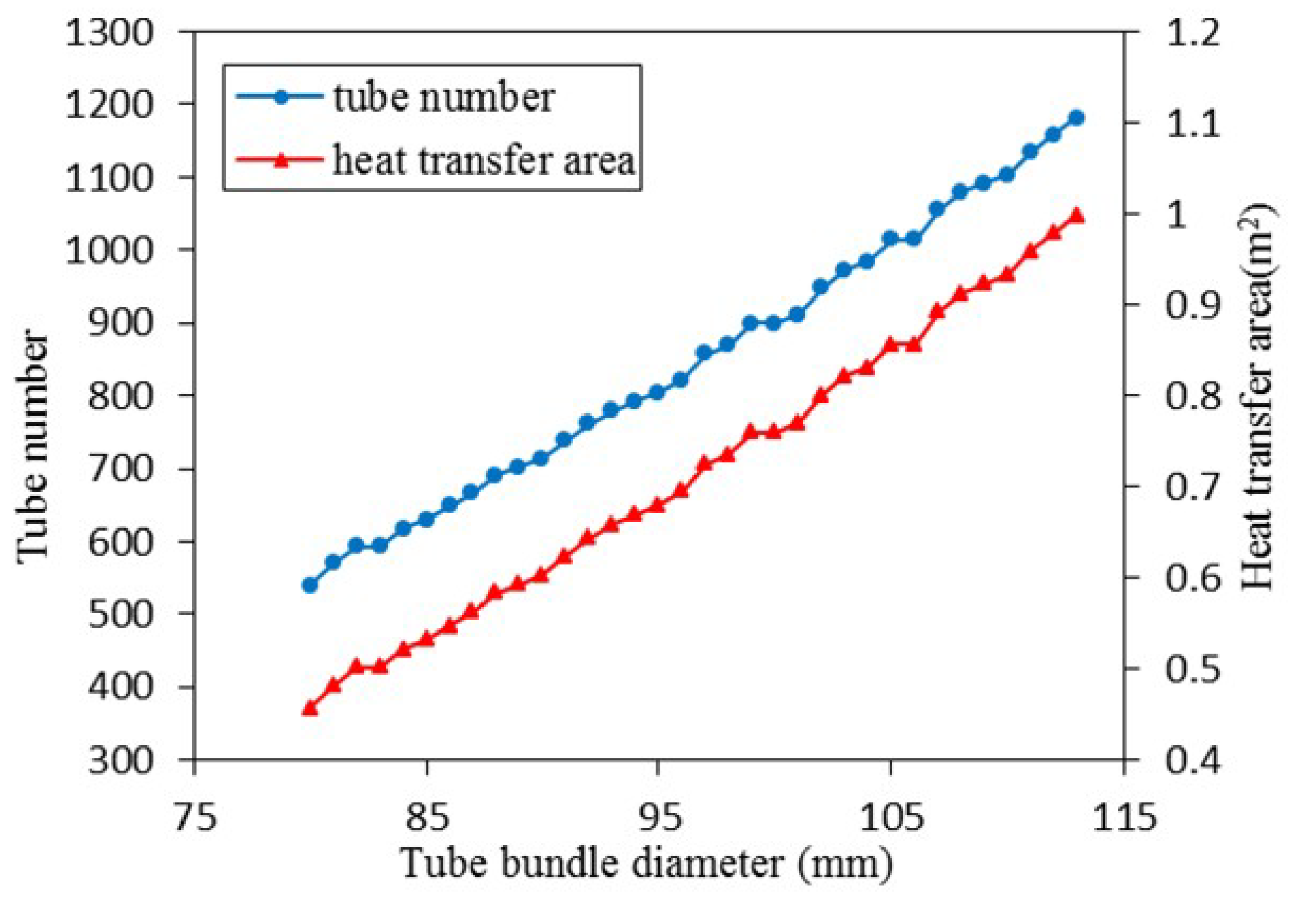
4.2.1. Effects of Tube Bundle Diameter

The effects of tube bundle diameter Do on heat transfer capacity Q and shell-side pressure drop ∆P of STHX-DDB are represented in Figure 6 while inside tube bundle diameter and number of baffles are 20 mm and 3, respectively. As depicted, while tube bundle diameter increases from 80 mm to 113 mm, heat transfer capacity increases by 11.47–16.19 kW, and shell-side pressure drop drops slowly from 14.76 kPa first, reaching its lowest point of 14.27 kPa when tube bundle diameter is 102 mm, and then rises more and more dramatically to 19.02 kPa. As shown in Figure 7, as tube bundle diameter increases, the number of tubes increases. Thus, heat transfer area increases, which enhances heat transfer capacity. In addition, the growth of tube bundle diameter means that the flow area between baffles increases and the flow area between disc baffles and shell decreases, which results in the decrease of the pressure drop between baffles and the increase of the pressure drop between disc baffles and shell. Moreover, the pressure drop between disc baffles and shell grows increasingly significantly after tube bundle diameter reaches 102 mm. Thus, shell-side pressure drop falls increasingly slowly first and then grows increasingly sharply after tube bundle diameter reaches 102 mm.

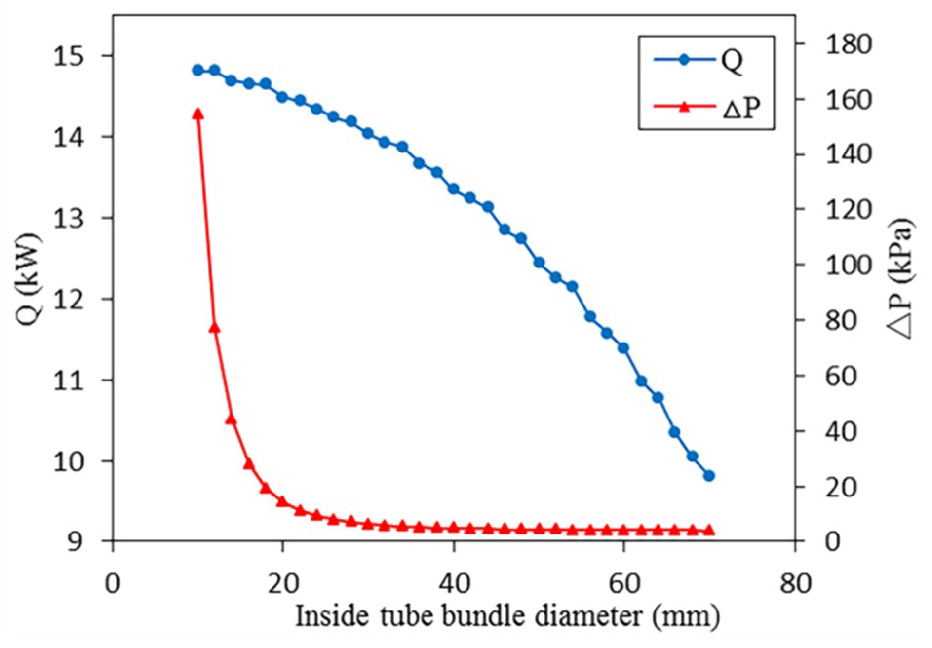
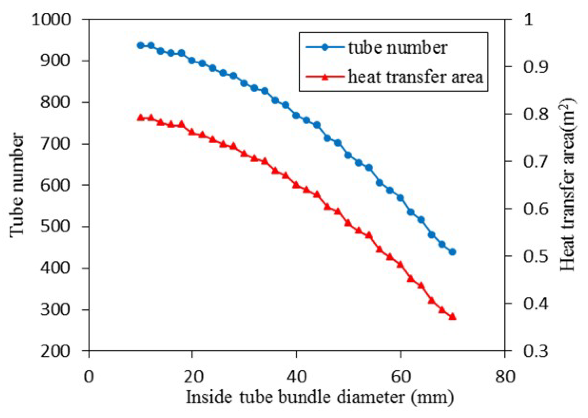
4.2.2. Effects of Inside Tube Bundle Diameter

The effects of inside tube bundle diameter Di on heat transfer capacity Q and shell-side pressure drop ∆P of STHX-DDB are represented in Figure 8 while tube bundle diameter and number of baffles are 100 mm and 3, respectively. As depicted, while inside tube bundle diameter increases from 10 mm to 70 mm, heat transfer capacity decreases by 14.82–9.80 kW, and shell-side pressure drop drops significantly from 154.42 kPa first, reaching the point of 5.96 kPa when inside tube bundle diameter is 32 mm, and then falls slightly to 4.05 kPa. As shown in Figure 9, the increase of inside tube bundle diameter results in the decrease of number of tubes and the growth of flow area of the central hole of doughnut baffles. Thus, both heat transfer capacity and shell-side pressure drop decrease. As the impact on shell-side pressure drop is more serious before the point of 5.96 kPa than after, the figure decreases more seriously before this point than after.

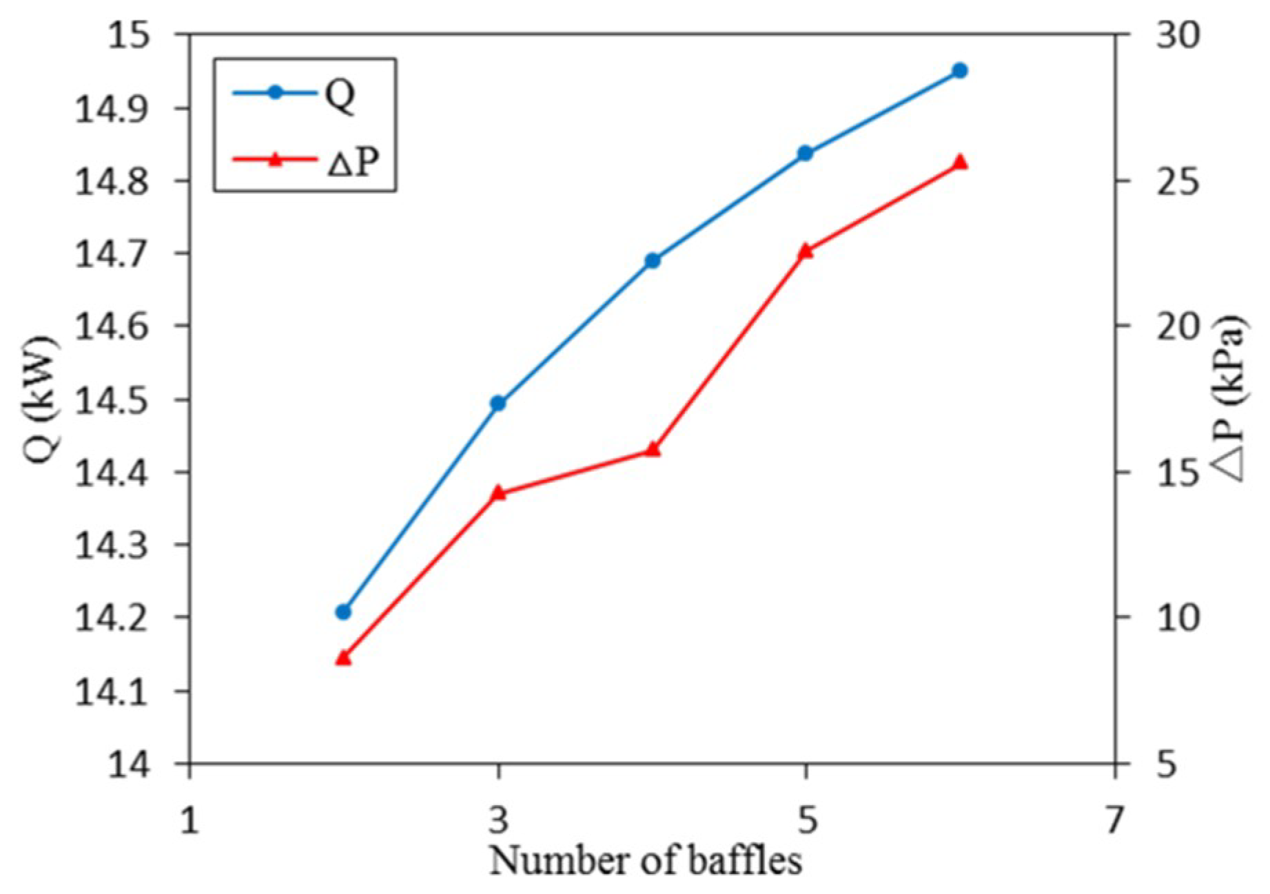
4.2.3. Effects of Number of Baffles

The effects of number of baffles Nb on heat transfer capacity Q and shell-side pressure drop ∆P of STHX-DDB are represented in Figure 10 while tube bundle diameter and inside tube bundle diameter are 100 mm and 20 mm, respectively. As depicted, while number of baffles increases from 2 to 6, heat transfer capacity and shell-side pressure drop increase by 14.21–14.95 kW and 8.63–25.60 kPa, respectively. As number of baffles increases, the distance between baffles decreases, which leads to the increase of fluid velocity between baffles. Thus, both heat transfer capacity and shell-side pressure drop increase. In addition, as number of baffles grows, disc baffle number and doughnut baffle number increase alternately, which results in an unsmooth figure of shell-side pressure drop.

4.3. Design Parameter Effects of STHX-SB

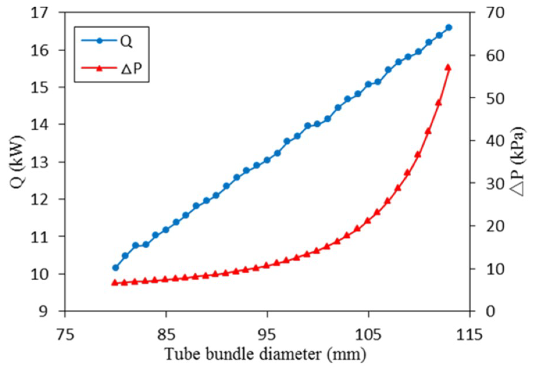
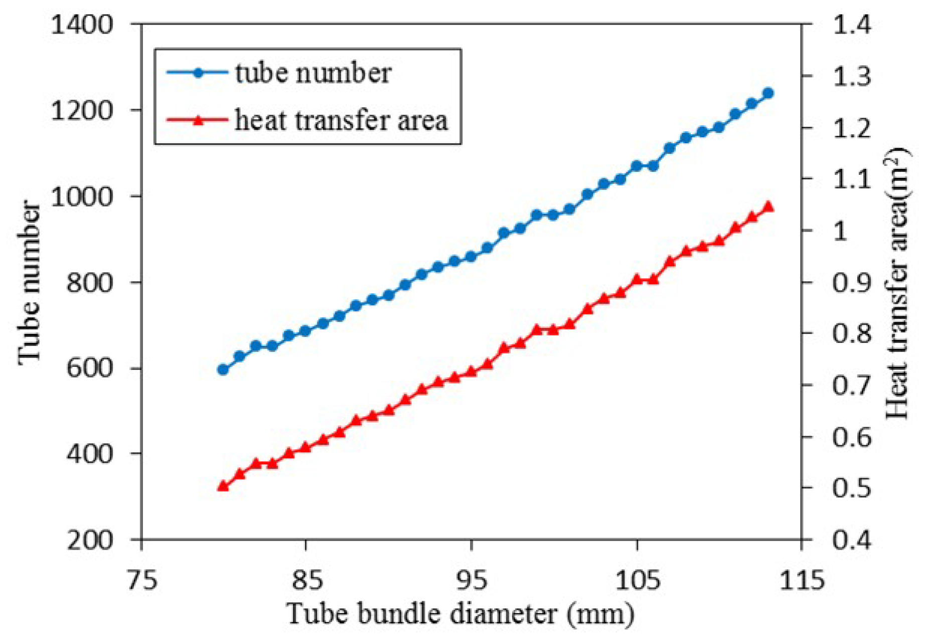
4.3.1. Effects of Tube Bundle Diameter

The effects of tube bundle diameter Do on heat transfer capacity Q and shell-side pressure drop ∆P of STHX-SB are represented in Figure 11 while baffle cut and number of baffles are 0.25 and 3, respectively. As depicted, while tube bundle diameter increases from 80 mm to 113 mm, heat transfer capacity and shell-side pressure drop increase by 10.16–16.60 kW and 6.59–57.07 kPa, respectively. As shown in Figure 12, as tube bundle diameter grows, the number of tubes increases, which improves heat transfer capacity. At the same time, both the flow areas of cross flow region and window region decrease, which leads to a higher shell-side pressure drop.

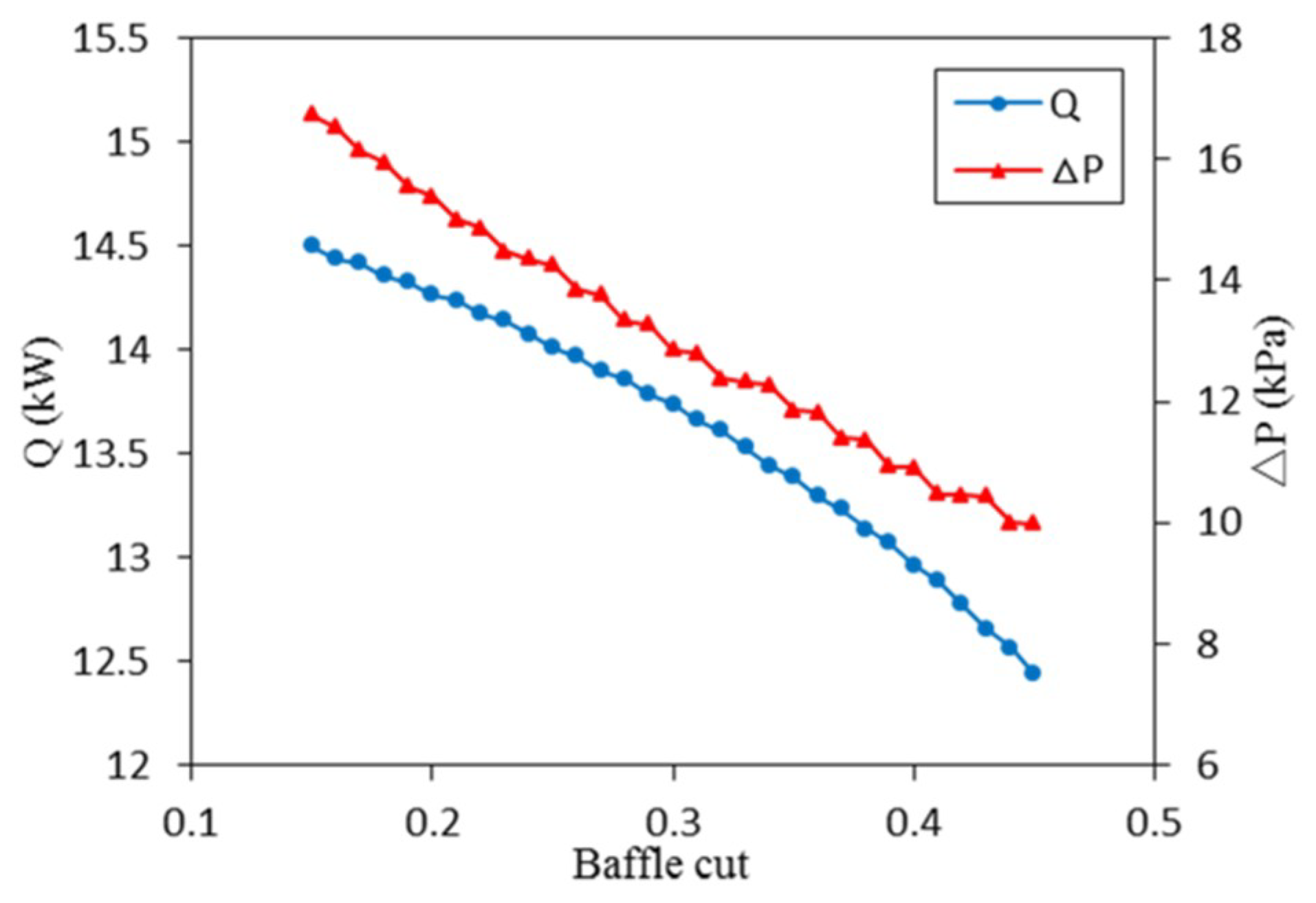
4.3.2. Effects of Baffle Cut

The effects of baffle cut P on heat transfer capacity Q and shell-side pressure drop ∆P of STHX-SB are represented in Figure 13 while tube bundle diameter and number of baffles are 100 mm and 3, respectively. As depicted, while baffle cut increases from 0.15 to 0.45, heat transfer capacity and shell-side pressure drop decrease by 14.50–12.44 kW and 16.74–9.99 kPa, respectively. The increase of baffle cut means that cross flow decreases and parallel flow increases. As cross flow has a better heat transfer effect and a bigger pressure drop than parallel flow, both heat transfer capacity and shell-side pressure drop decrease.

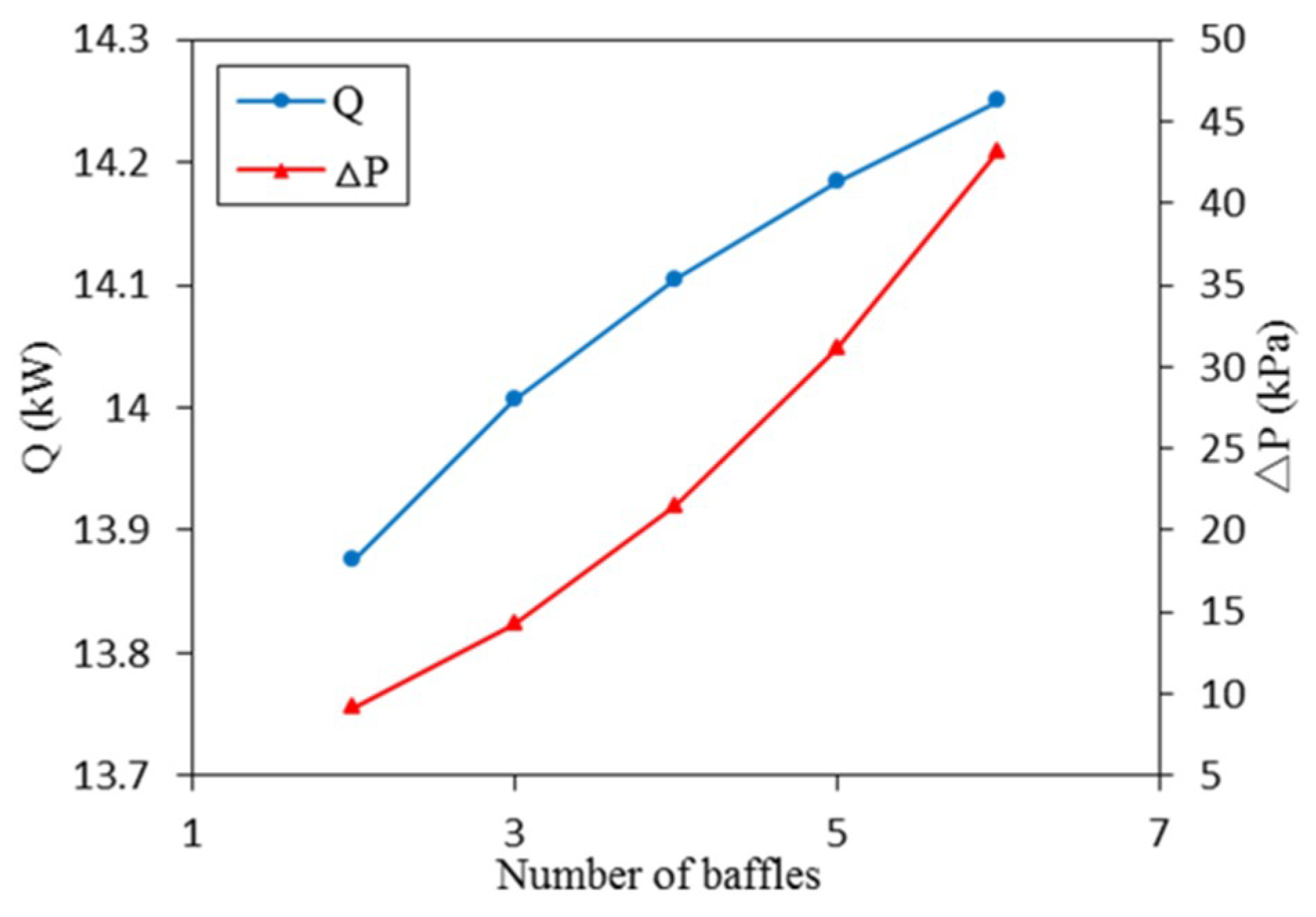
4.3.3. Number of Baffles

The effects of number of baffles Nb on heat transfer capacity Q and shell-side pressure drop ∆P of STHX-SB are represented in Figure 14 while tube bundle diameter and baffle cut are 100 mm and 0.25, respectively. As depicted, while number of baffles increases from 2 to 6, heat transfer capacity and shell-side pressure drop increase by 13.88–14.25 kW and 9.17–43.22 kPa, respectively. As number of baffles increases, turbulence of fluid is strengthened. Thus, both heat transfer capacity and shell-side pressure drop increase.

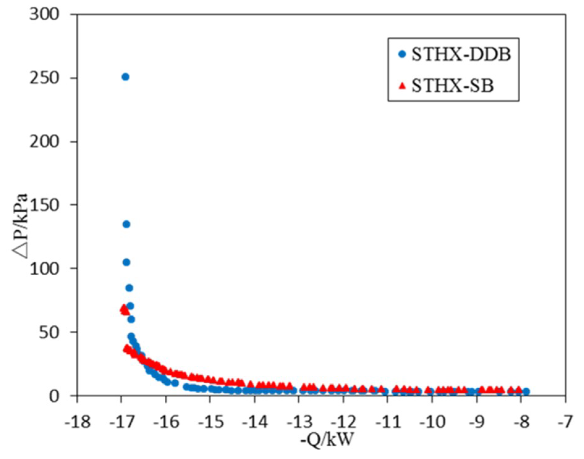
4.4. Multi-Objective Optimization Results

In order to consider the comprehensive thermohydraulic performances of STHX-DDB and STHX-SB, the multi-objective configuration optimization using NSGA-II is conducted. The optimization goals are to maximize heat transfer capacity and to minimize shell-side pressure drop, and two objective functions (−Q and ∆P) are conflicting. Population size, maximum iteration number, analog binary cross distribution index and polynomial mutation distribution index, which are main settings of optimization, are 100, 500, 20 and 20, respectively. Figure 15 shows the Pareto optimal points which are obtained based on the objective functions and the design parameters described in Equations (1) and (2), and the Pareto optimal points in the heat transfer capacity ranges of 7.5–16.5 kW and 16.5–17 kW are shown in Figure 16 and Figure 17, respectively.
As shown in Figure 15, for both heat exchangers, shell-side pressure drop increases with the growth of heat transfer capacity. Especially in the range of high heat transfer capacity, shell-side pressure drop increases significantly sharply. As depicted in Figure 16, after optimization, for the same heat transfer capacity, the shell-side pressure drop of STHX-DDB is lower than this value of STHX-SB in the heat transfer capacity range of 7.5–16.5 kW. Thus, STHX-DDB has a better thermohydraulic performance than STHX-SB in this range. As shown in Figure 17, after optimization, for the same heat transfer capacity, the shell-side pressure drop of STHX-DDB is above or almost equal to this value of STHX-SB in the heat transfer capacity range of 16.5–17 kW. Thus, in this high range of heat transfer capacity, the thermohydraulic performance of STHX-SB is better.
Three Pareto optimal solutions for STHX-DDB and three Pareto optimal solutions for STHX-SB are chosen and shown in Figure 16, Table 3 and Table 4. For either STHX-DDB or STHX-SB, the selection method of three Pareto optimal solutions follows the following principles:
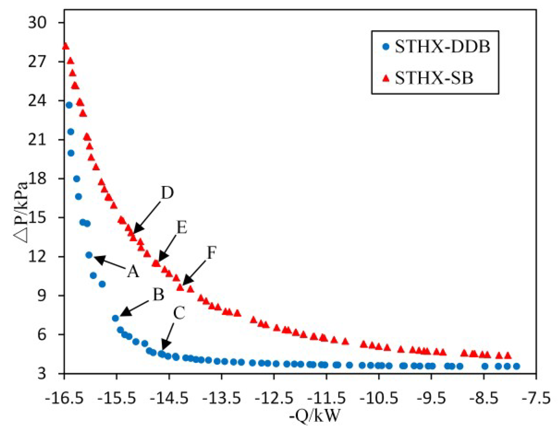
  • The heat transfer capacity of the first Pareto optimal solution is much higher than the original configuration, while the shell-side pressure drop of it is a little lower than the original configuration.
  • The heat transfer capacity of the third Pareto optimal solution is a little higher than the original configuration, while the shell-side pressure drop of it is much lower than the original configuration.
  • The second Pareto optimal solution is chosen from almost the middle position in the range from the first Pareto optimal solution to the third.
Compared with the original configuration of STHX-DDB shown in Table 3, the heat transfer capacity values of optimal configuration A, B and C increase separately by 10.56%, 7.11% and 1.10%, and the shell-side pressure drop values of them decrease by 15.20%, 49.30% and 68.49%, respectively. It is clearly depicted that the heat transfer capacity of optimal configurations of STHX-DDB increases by 6.26% on average, while the shell-side pressure drop decreases by 44.33% on average. Compared with the original configuration of STHX-SB shown in Table 4, the heat transfer capacity values of optimal configuration D, E and F increase separately by 8.35%, 5.14% and 2.00%, and the shell-side pressure drop values of them decrease by 5.61%, 19.51% and 32.35%, respectively. It is clearly shown that the heat transfer capacity of optimal configurations of STHX-SB increases by 5.16% on average, while the shell-side pressure drop decreases by 19.16% on average. Based on the comparison and analysis of original and optimal configurations, it indicates that the optimization method is valid and feasible, and the comprehensive thermohydraulic performances of STHX-DDB and STHX-SB can be enhanced by the optimization method.

5. Conclusions

In this paper, a multi-objective configuration optimization method for STHX-DDB and STHX-SB based on NSGA-II is proposed and used. Based on the thermohydraulic calculation model verified in this paper, the effects of design parameters are analyzed. Then, the optimal design parameters (tube bundle diameter, inside tube bundle diameter, number of baffles) for STHX-DDB and the optimal design parameters (tube bundle diameter, baffle cut, number of baffles) for STHX-SB are found separately by a trade-off between the two common objectives of heat transfer capacity maximization and shell-side pressure drop minimization.
The distribution of Pareto optimal points reveals that the two objectives are conflicted, and, for both heat exchangers, shell-side pressure drop increases significantly sharply in the range of high heat transfer capacity, which means that high heat transfer capacity will cost a high shell-side pressure drop. In addition, after optimization, except in the high range of heat transfer capacity of 16.5–17 kW, the shell-side pressure drop of STHX-DDB is lower than this value of STHX-SB when the heat transfer capacity values of them are the same. In other words, under this condition, the thermohydraulic performance of STHX-DDB is better.
Finally, three optimal solutions for STHX-DDB and three optimal solutions for STHX-SB are selected and compared with the original configurations. The results illustrate that all the selected optimal configurations are better than the original configurations. For STHX-DDB, the heat transfer capacity of optimal configurations increases by 6.26% on average compared with the original configuration, while the shell-side pressure drop decreases by 44.33% on average. For STHX-SB, the heat transfer capacity of optimal configurations increases by 5.16% on average compared with the original configuration, while the shell-side pressure drop decreases by 19.16% on average. It indicates that the optimization method is feasible and valid and can provide a significant reference for STHX design.

Author Contributions

Conceptualization, Z.X.; Investigation, Z.X. and H.M.; Methodology, Z.X.; Project administration, Y.G.; Resources, Z.X.; Software, Z.X.; Supervision, Y.G.; Validation, Z.X.; Visualization, Z.X.; Writing—original draft, Z.X.; Writing—review and editing, Z.X., Y.G. and F.Y.

Funding

This research received no external funding.

Conflicts of Interest

The authors declare no conflict of interest.

Nomenclature

Latin letters
Aheat transfer aream2
C*heat capacity ratio-
Cpspecific heat capacityJ/(kg·K)
deequivalent diameterm
diinside tube diameterm
dmaverage tube diameterm
dooutside tube diameterm
ffriction coefficient-
Ktotal heat transfer coefficient W/(m2·K)
Ltube lengthm
lbspace between bafflesm
ntotal number of tube rows-
NBnumber of baffles-
NB1number of disc baffles-
NB2number of doughnut baffles-
Ncumber of tubes in cross flow region-
Ncwnumber of tubes in window region-
NTUnumber of transfer units-
PrPrandtl number-
Pttube pitchm
Qheat transfer capacityW
qmmass flow ratekg/s
ReReynolds number-
rs,ifouling resistance inside tubem2·K/W
rs,ofouling resistance outside tubem2·K/W
Scirculation aream2
ttemperatureK
t1inlet temperature of hot sideK
t2inlet temperature of cold sideK
ufluid velocitym/s
Wheat capacityW/K
Greek letters
αheat transfer coefficientW/(m2·K)
δthicknessm
ΔPshell-side pressure dropPa
εresistance coefficient-
ηheat transfer efficiency-
λheat conductivityW/(m·K)
μfluid viscosityPa·s
ρfluid densitykg/m3
Subscripts
itube-side
oshell-side
wtube wall
Noutlet/inlet
Bbetween baffles
s1between disc baffles and shell
s2central hole of doughnut baffles
bkcross flow region
wkwindow region

Appendix A

Basic formulas of heat transfer capacity calculation. The basic formula of heat transfer capacity calculation of heat exchanger is given by Equation (A1) [29]:
Q = η W min ( t 1 t 2 ) .
As the number of shell passes and tube passes are 1 and 2, respectively, η is given by Equations (A2)–(A6) [29,35]:
η = 2 1 + C * + 1 + C * 2 ( 1 + e NTU 1 + C * 2 ) / ( 1 e NTU 1 + C * 2 ) ,
C * = W min / W max ,
NTU = K A W min ,
1 K = 1 α i ( d o d i ) + r s , i ( d o d i ) + δ w λ w ( d o d m ) + r s , o + 1 α o ,
d m = d o d i ln ( d o / d i ) .
In general, the thermal-conduction resistance of a metal tube wall is much smaller than the thermal resistance of fluids’ heat convection, and, for the new heat exchanger, the fouling resistance can be neglected. In addition, the tube wall thickness used in this case is only 0.305 mm, which is too small to be ignored. Thus, Equation (A5) can be simplified to Equation (A7) [29]:
K = α o α i α o + α i .
For STHXs, αi is given by Equations (A8)–(A10) [26]:
α i = 0.027 λ i d i Re i 0.8 Pr i 1 / 3 ( μ i μ iw ) 0.14
(Rei > 10,000, 0.7 < Pri < 16,700, L d i 60 ),
α i = 0.027 ( 1 6 × 10 5 Re i 1.8 ) λ i d i Re i 0.8 Pr i 1 / 3 ( μ i μ iw ) 0.14
(2300 ≤ Rei ≤ 10,000, 0.7 < Pri < 16,700, L d i 60 ),
α i = 1.86 λ i d i ( Re i Pr i d i L ) 1 / 3 ( μ i μ iw ) 0.14
(Rei <2300, 0.6 < Pri < 6700, Re i Pr i L d i 100 ).
In Equations (A8)–(A10), µiw is the viscosity of tube-side fluid under the temperature of tube wall.
Because of the different shell-side structures between STHX-DDB and STHX-SB, αo calculation formulas are different. For STHX-DDB, the Slipcevie method is used, and αo is given by Equations (A11) and (A12) [26]:
α o = j = 1 n A ( j ) A α o ( j ) ,
α o ( j ) = 0.33 λ o d o Re o 0.6 ( j ) Pr o 0.33 ( t o t w ) 0.14 .
In Equations (A11) and (A12), A(j), αo(j) and Reo(j) represent heat transfer area, heat transfer coefficient and Reynolds number of the fluid over the tube row of j, respectively.
For STHX-SB, the Bell–Delaware method is used and αo is given by Equation (A13) [26,27,28,29]:
α o = α id J c J l J b J s J r .
In Equation (A13), αid is the ideal heat transfer coefficient for pure cross flow over a tube bundle. Jc, Jl, Jb, Js and Jr represent correction factors for baffle cut, baffle leakage, bundle bypassing, variable baffle spacing at the inlet and outlet of shell, and adverse temperature gradient in laminar flow, respectively.
Re and Pr used in the calculation above can be calculated by Equations (A14)–(A16) [29]:
Re = ρ ud e μ ,
Pr = μ C p λ ,
u = q m ρ S .

Appendix B

Basic formulas of shell-side pressure drop calculation. Because of the different shell-side structures between STHX-DDB and STHX-SB, formulas of ∆P calculation are different.
For STHX-DDB, ∆P is given by Equations (A17)–(A24) [36]:
Δ P = Δ P N + Δ P B + Δ P s 1 + Δ P s 2 ,
Δ P N = 1.5 ρ o u N 2 2 ,
Δ P B = ε B ( N B + 1 ) ρ o u B 2 2 ,
Δ P s 1 = N B 1 ε s 1 ρ o u s 1 2 2 ,
Δ P s 2 = N B 2 ε s 2 ρ o u s 2 2 2 ,
ε B = { 60 L d o d o Re B ( Re B < 42.3 d o L d o ) 3 ( L d o d o Re B ) 0.2 ( Re B 42.3 d o L d o ) ,
ε s 1 = 2.2 + 286 Re s 1 0.845 ,
ε s 2 = 2.2 + 286 Re s 2 0.845 .
For STHX-SB, the Bell-Delaware method is used and ∆P is given by Equations (A25)–(A28) [26,27,28].
Δ P = 2 Δ P bk R b ( 1 + N cw N c ) R s + [ ( N B 1 ) Δ P bk R b + N B Δ P wk ] R l + Δ P N ,
Δ P bk = 4 f o N c ρ o u bk 2 2 ( μ o μ ow ) 0.14 ,
f o = { 47.1 Re bk 0.965 ( Re bk < 100 ) 13.0 Re bk 0.685 ( 100 Re bk 300 ) 3.2 Re bk 0.44 ( 300 < Re bk 1000 ) 0.505 Re bk 0.176 ( Re bk > 1000 ) ,
Δ P wk = { ( 2 + 0.6 N cw ) ρ o u wk 2 2 ( Re wk 100 ) 26 μ o u wk ( N cw p t d o + l b d ew 2 ) + 2 ( ρ o u wk 2 2 ) ( Re wk < 100 ) .
In Equations (A25)–(A28), Rb, Rl, Rs represent correction factors for bundle bypassing, baffle leakage, and variable baffle spacing at the inlet and outlet of shell, respectively. µow is the viscosity of shell-side fluid under the temperature of tube wall. dew is the equivalent diameter of tube bundle in the window region.

References

  1. Bayram, H.; Sevilgen, G. Numerical Investigation of the Effect of Variable Baffle Spacing on the Thermal Performance of a Shell and Tube Heat Exchanger. Energies 2017, 10, 1156. [Google Scholar] [CrossRef]
  2. Wang, Y.; Huai, X. Heat Transfer and Entropy Generation Analysis of an Intermediate Heat Exchanger in ADS. J. Therm. Sci. 2018, 27, 175–183. [Google Scholar] [CrossRef]
  3. Xiao, W.; Wang, K.; Jiang, X.; He, G. Optimization of a shell-and-tube heat exchanger based on a genetic simulated annealing algorithm. J. Tsinghua Univ. (Sci. Technol.) 2016, 56, 728–734. [Google Scholar]
  4. Hadidi, A.; Nazari, A. Design and economic optimization of shell-and-tube heat exchangers using biogeography-based (BBO) algorithm. Appl. Therm. Eng. 2013, 51, 1263–1272. [Google Scholar] [CrossRef]
  5. Mohanty, D.K. Application of firefly algorithm for design optimization of a shell and tube heat exchanger from economic point of view. Int. J. Therm. Sci. 2016, 102, 228–238. [Google Scholar] [CrossRef]
  6. Rao, R.V.; Saroj, A. Economic optimization of shell-and-tube heat exchanger using Jaya algorithm with maintenance consideration. Appl. Therm. Eng. 2017, 116, 473–487. [Google Scholar] [CrossRef]
  7. Singh, P.; Pant, M. Design Optimization of Shell and Tube Heat Exchanger Using Differential Evolution Algorithm. In Proceedings of the Third International Conference on Soft Computing for Problem Solving; Springer: New Delhi, India, 2014. [Google Scholar]
  8. Sanaye, S.; Hajabdollahi, H. Multi-objective optimization of shell and tube heat exchangers. Appl. Therm. Eng. 2010, 30, 1937–1945. [Google Scholar] [CrossRef]
  9. Wen, J.; Gu, X.; Wang, M.; Wang, S.; Tu, J. Numerical investigation on the multi-objective optimization of a shell-and-tube heat exchanger with helical baffles. Int. Commun. Heat Mass 2017, 89, 91–97. [Google Scholar] [CrossRef]
  10. Wang, S.; Xiao, J.; Wang, J.; Jian, G.; Wen, J.; Zhang, Z. Configuration optimization of shell-and-tube heat exchangers with helical baffles using multi-objective genetic algorithm based on fluid-structure interaction. Int. Commun. Heat Mass 2017, 85, 62–69. [Google Scholar] [CrossRef]
  11. Wang, S.; Xiao, J.; Wang, J.; Jian, G.; Wen, J.; Zhang, Z. Application of response surface method and multi-objective genetic algorithm to configuration optimization of shell-and-tube heat exchanger with fold helical baffles. Appl. Therm. Eng. 2018, 129, 512–520. [Google Scholar] [CrossRef]
  12. Wang, S.; Jian, G.; Xiao, J.; Wen, J.; Zhang, Z.; Tu, J. Fluid-thermal-structural analysis and structural optimization of spiral-wound heat exchanger. Int. Commun. Heat Mass 2018, 95, 42–52. [Google Scholar] [CrossRef]
  13. Amidpour, M.; Azad, A.V. Economic optimization of shell and tube heat exchanger based on constructal theory. In Proceedings of the ASME 2010 4th International Conference on Energy Sustainability, Phoenix, AZ, USA, 17–22 May 2010. [Google Scholar]
  14. Mirzaei, M.; Hajabdollahi, H.; Fadakar, H. Multi-objective optimization of shell-and-tube heat exchanger by constructal theory. Appl. Therm. Eng. 2017, 125, 9–19. [Google Scholar] [CrossRef]
  15. Gu, X.; Wang, M.; Liu, Y.; Wang, S. Multi-parameter optimization of shell-and-tube heat exchanger with helical baffles based on entransy theory. Appl. Therm. Eng. 2018, 130, 804–813. [Google Scholar]
  16. Chahartaghi, M.; Eslami, P.; Naminezhad, A. Effectiveness improvement and optimization of shell-and-tube heat exchanger with entransy method. Heat Mass Transf. 2018, 54, 3771–3784. [Google Scholar] [CrossRef]
  17. Rao, R.V.; Patel, V. Multi-objective optimization of heat exchangers using a modified teaching-learning-based optimization algorithm. Appl. Math. Model. 2013, 37, 1147–1162. [Google Scholar] [CrossRef]
  18. Ghanei, A.; Assareh, E.; Biglari, M.; Ghanbarzadeh, A.; Noghrehabadi, A.R. Thermal-economic multi-objective optimization of shell and tube heat exchanger using particle swarm optimization (PSO). Heat Mass Transf. 2014, 50, 1375–1384. [Google Scholar] [CrossRef]
  19. Etghani, M.M.; Baboli, S.A.H. Numerical investigation and optimization of heat transfer and exergy loss in shell and helical tube heat exchanger. Appl. Therm. Eng. 2017, 121, 294–301. [Google Scholar] [CrossRef]
  20. Tharakeshwar, T.K.; Seetharamu, K.N.; Prasad, B.D. Multi-objective optimization using bat algorithm for shell and tube heat exchangers. Appl. Therm. Eng. 2017, 110, 1029–1038. [Google Scholar] [CrossRef]
  21. Raja, B.D.; Jhala, R.L.; Patel, V. Many-objective optimization of shell and tube heat exchanger. Therm. Sci. Eng. Prog. 2017, 2, 87–101. [Google Scholar] [CrossRef]
  22. Rao, B.B.; Raju, V.R.; Deepak, B. Estimation and optimization of heat transfer and overall pressure drop for a shell and tube heat exchanger. J. Mech. Sci. Technol. 2017, 31, 375–383. [Google Scholar] [CrossRef]
  23. Saldanha, W.H.; Soares, G.L.; Machado-Coelho, T.M.; dos Santos, E.D.; Ekel, P.I. Choosing the best evolutionary algorithm to optimize the multiobjective shell-and-tube heat exchanger design problem using PROMETHEE. Appl. Therm. Eng. 2017, 127, 1049–1061. [Google Scholar] [CrossRef]
  24. Wang, X.; Zheng, N.; Liu, Z.; Liu, W. Numerical analysis and optimization study on shell-side performances of a shell and tube heat exchanger with staggered baffles. Int. J. Heat Mass Transf. 2018, 124, 247–259. [Google Scholar] [CrossRef]
  25. Gu, X.; Zheng, Z.; Xiong, X.; Wang, T.; Luo, Y.; Wang, K. Characteristics of Fluid Flow and Heat Transfer in the Shell Side of the Trapezoidal-like Tilted Baffles Heat Exchanger. J. Therm. Sci. 2018, 27, 602–610. [Google Scholar] [CrossRef]
  26. Qian, S. Heat Exchanger Design Manual; Chemistry Industry Publisher: Beijing, China, 2002; pp. 55–108. [Google Scholar]
  27. Thulukkanam, K. Heat Exchanger Design Handbook, 2nd ed.; CRC Press: New York, NY, USA, 2013; pp. 39–115. [Google Scholar]
  28. Shah, R.K.; Sekulic, D.P. Fundamentals of Heat Exchanger Design; John Wiley & Sons: New York, NY, USA, 2003; pp. 583–610. [Google Scholar]
  29. Shi, M.; Wang, Z. Principle and Design of Heat Exchangers, 4th ed.; Southeast University Press: Nanjing, China, 2009; pp. 53–107. [Google Scholar]
  30. Yue, S.; Wang, Y.; Wang, H. Design and optimization of tandem arranged cascade in a transonic compressor. J. Therm. Sci. 2018, 27, 349–358. [Google Scholar] [CrossRef]
  31. Wen, J.; Yang, H.; Jian, G.; Tong, X.; Li, K.; Wang, S. Energy and cost optimization of shell and tube heat exchanger with helical baffles using Kriging metamodel based on MOGA. Int. J. Heat Mass Transf. 2016, 98, 29–39. [Google Scholar] [CrossRef]
  32. Wen, J.; Yang, H.; Tong, X.; Li, K.; Wang, S.; Li, Y. Optimization investigation on configuration parameters of serrated fin in plate-fin heat exchanger using genetic algorithm. Int. J. Therm. Sci. 2016, 101, 116–125. [Google Scholar] [CrossRef]
  33. Wen, J.; Yang, H.; Tong, X.; Li, K.; Wang, S.; Li, Y. Configuration parameters design and optimization for plate-fin heat exchangers with serrated fin by multi-objective genetic algorithm. Energ. Convers. Manag. 2016, 117, 482–489. [Google Scholar] [CrossRef]
  34. Deb, K.; Pratap, A.; Agarwal, S.; Meyarivan, T. A fast and elitist multiobjective genetic algorithm: NSGA-II. IEEE Trans. Evol. Comput. 2002, 6, 182–197. [Google Scholar] [CrossRef] [Green Version]
  35. Kays, W.M.; London, A.L. Compact Heat Exchangers, 3rd ed.; McGraw-Hill: New York, NY, USA, 1984; pp. 11–78. [Google Scholar]
  36. Dong, Q.; Zhang, Y. Petrochemical Equipment Design and Selection Manual: Heat Exchanger; Chemistry Industry Publisher: Beijing, China, 2008; pp. 66–115. [Google Scholar]
Figure 1. Differences between shell-and-tube heat exchanger with disc-and-doughnut baffles (STHX-DDB) and shell-and-tube heat exchanger with segmental baffles (STHX-SB): (a) STHX-DDB; (b) STHX-SB.
Energies 12 01794 g001
Figure 2. Flowchart of the thermohydraulic calculation model.
Energies 12 01794 g002
Figure 3. Flowchart of the optimization method.
Energies 12 01794 g003
Figure 4. Testing equipment: (a) testing equipment of the oil side; (b) one part of testing equipment of the fuel side; (c) the other part of testing equipment of the fuel side.
Energies 12 01794 g004
Figure 5. Comparison between calculation results and experimental data: (a) heat transfer capacity; (b) shell-side pressure drop.
Energies 12 01794 g005
Figure 6. Heat transfer capacity and shell-side pressure drop separately versus tube bundle diameter.
Energies 12 01794 g006
Figure 7. Tube number and heat transfer area separately versus tube bundle diameter.
Energies 12 01794 g007
Figure 8. Heat transfer capacity and shell-side pressure drop separately versus inside tube bundle diameter.
Energies 12 01794 g008
Figure 9. Tube number and heat transfer area separately versus inside tube bundle diameter.
Energies 12 01794 g009
Figure 10. Heat transfer capacity and shell-side pressure drop separately versus number of baffles.
Energies 12 01794 g010
Figure 11. Heat transfer capacity and shell-side pressure drop separately versus tube bundle diameter.
Energies 12 01794 g011
Figure 12. Tube number and heat transfer area separately versus tube bundle diameter.
Energies 12 01794 g012
Figure 13. Heat transfer capacity and shell-side pressure drop separately versus baffle cut.
Energies 12 01794 g013
Figure 14. Heat transfer capacity and shell-side pressure drop separately versus number of baffles.
Energies 12 01794 g014
Figure 15. Pareto optimal points.
Energies 12 01794 g015
Figure 16. Pareto optimal points for the heat transfer capacity range of 7.5–16.5 kW.
Energies 12 01794 g016
Figure 17. Pareto optimal points for the heat transfer capacity range of 16.5–17 kW.
Energies 12 01794 g017
Table 1. Configuration parameters of STHX-DDB and STHX-SB.
STHX-DDBValueSTHX-SBValue
Tube bundle diameter (mm)100Tube bundle diameter (mm)100
Inside tube bundle diameter (mm)20Baffle cut0.25
Inside shell diameter (mm)115Inside shell diameter (mm)115
Tube pitch (mm)3Tube pitch (mm)3
Outside tube diameter (mm)2.36Outside tube diameter (mm)2.36
Inside tube diameter (mm)1.75Inside tube diameter (mm)1.75
Tube length (mm)130Tube length (mm)130
Number of baffles3Number of baffles3
Baffle thickness (mm)1.5Baffle thickness (mm)1.5
Number of end plates2Number of end plates2
End plate thickness (mm)8End plate thickness (mm)8
Number of shell passes1Number of shell passes1
Number of tube passes2Number of tube passes2
Inlet/Outlet diameter of shell/tube-side (mm)20Inlet/Outlet diameter of shell/tube-side (mm)20
Table 2. Experiment conditions for STHX-DDB and STHX-SB.
Experiment ConditionValue
Inlet flow rate of tube-side (L/min)20
Inlet flow rate of shell-side (L/min)40
Inlet temperature of tube-side (K)323
Inlet temperature of shell-side (K)383
Table 3. Optimization thermohydraulic performances comparison of STHX-DDB.
ParametersDo (mm)Di (mm)NbQ (kW)P (kPa)
Original configuration10020314.4914.28
Optimal configuration A11223316.0212.11
Optimal configuration B11124215.527.24
Optimal configuration C10734214.654.50
Table 4. Optimization thermohydraulic performances comparison of STHX-SB.
ParametersDo (mm)PNbQ (kW)P (kPa)
Original configuration1000.25314.0114.25
Optimal configuration D1050.21215.1813.45
Optimal configuration E1030.22214.7311.47
Optimal configuration F990.17214.299.64

