Article

Cooling Technologies for High Power Density Electrical Machines for Aviation Applications

Institute of Electrical Machines, Traction and Drives; TU Braunschweig; 38106 Braunschweig, Germany
*
Author to whom correspondence should be addressed.
Energies 2019, 12(23), 4579; https://doi.org/10.3390/en12234579
Submission received: 17 September 2019 / Revised: 22 November 2019 / Accepted: 26 November 2019 / Published: 1 December 2019
(This article belongs to the Section F: Electrical Engineering)

Abstract

:
This paper is aimed at giving an overview of possible cooling technologies for electrical machines and their assessment for aviation applications, e.g., fan or propeller drives. The most important demand for aircraft is the minimization of the drive system weight comprising electrical machine, power electronics, and the cooling system. The potential of aluminum winding an overview about several cooling technologies with the Rankine or Brayton cycle or utilizing the phase change of the cooling fluid is given. As an alternative approach, the cooling structure inside the machine is studied. A very interesting potential was discovered with direct slot cooling (DSC) removing the heat where it is produced and, thus, simplifying the cooling system effort and its weight. Since it is one of the most promising approaches, this cooling method is studied in depth. Furthermore, it can also be combined with one of the cooling technologies discussed above.

1. Introduction

Air traffic especially in Europe and USA delivers a significant contribution to the carbon dioxide emissions of the traffic sector. The vision for future airplanes is to equip them with an electrical drive system powered by batteries (small aircrafts) or hydrogen-based fuel cells. That is why electrical machines for fan drives in aviation are getting into the focus of development engineers. The dominant requirement is an extremely low weight of the drive to gain a competitive advantage with a modern aviation turbofan or propeller turbine. Currently, discussed figures are 10 to 20 kW per kg weight [1] of the machine, which are only are achievable with intense fluidic cooling and only where the higher value may be achieved with superconducting technologies. Another important figure that is seldom referenced is the drive system weight, respective of the weight of the electrical machine, inverter, and cooling system. All three components compose the drive system for a fan or propeller drive [2].
The conventional cooling system for electrical machines installed in aircraft, e.g., generators, is oil spray cooling using the oil from the turbine gear. This method is well established and documented in Reference [3]. In Reference [4], a heat pump is proposed for an oil spray cooling to raise the temperature level of the cooling fluid and to obtain smaller and lighter heat exchangers. Often the temperature level of the cooling oil is rather high, which requires a huge mass flow of oil and appropriate pumping capacity. Oil spray cooling also causes excessive rotor friction, which reduces the efficiency of the drive.
With industrial and automotive applications, water jacket cooling is a well-established cooling method [4] with the advantage of a simple mechanical structure and large heat capacity of water. In Reference [5], a water cooling system for an automotive drivetrain is combined with a heat pump to achieve convenient temperature levels for the cooling of the drive train components under summer and winter conditions.
In the overview paper [6], focus is set on the most recent progress in thermal management of electric motors for aviation. Besides air cooling, oil bath cooling, water jacket cooling, heat pipe cooling, intra winding cooling channels with a thermal conductive polymer [7], and direct winding cooling with tube-like conductors are cited. In this case, the problem of large pressure drops in the cooling ducts of six bars or more occurs. As experimental results, current densities of 24.7 A/mm2 and transient current density of more than 40 A/mm2 with class F insulation were achieved. With class H insulation even higher, values up to 58 A/mm2 could be possible. By using conductors with integrated cooling channels, current densities possibly reaching 130 A/mm2 were anticipated. However, the losses increase with the square of the current density and are linear with the volume of the winding even though the temperature is within the limits of the insulation system. The extremely high copper losses will increase weight and size of the cooling system and the reduced efficiency also requires an increase of the on-board power supply (generators and prime movers, fuel tank or energy storages, wiring, switchgear).
The weight advantages of such machines can be quickly overcompensated by the weight of the cooling system and the increased power supply. Therefore, an accurately balanced design of the drive system is necessary. A proposal for the improvement of this approach is given in Section 5.
A reduction of the winding temperature level by lowering the coolant temperature below standard ambient temperature promises a reduction of the copper losses in the electrical machine and a longer lifetime of the insulation. The higher effort for such cooling systems may be compensated by the higher efficiency of the drive. Due to the usually high temperature drop between winding and cooling fluid, this requires low ambient temperatures—as given in high cruising altitudes—or the use of refrigerant cooling systems, which allow coolant temperatures below ambient temperatures. In a literature study, no papers dealing with this question for aviation were found.
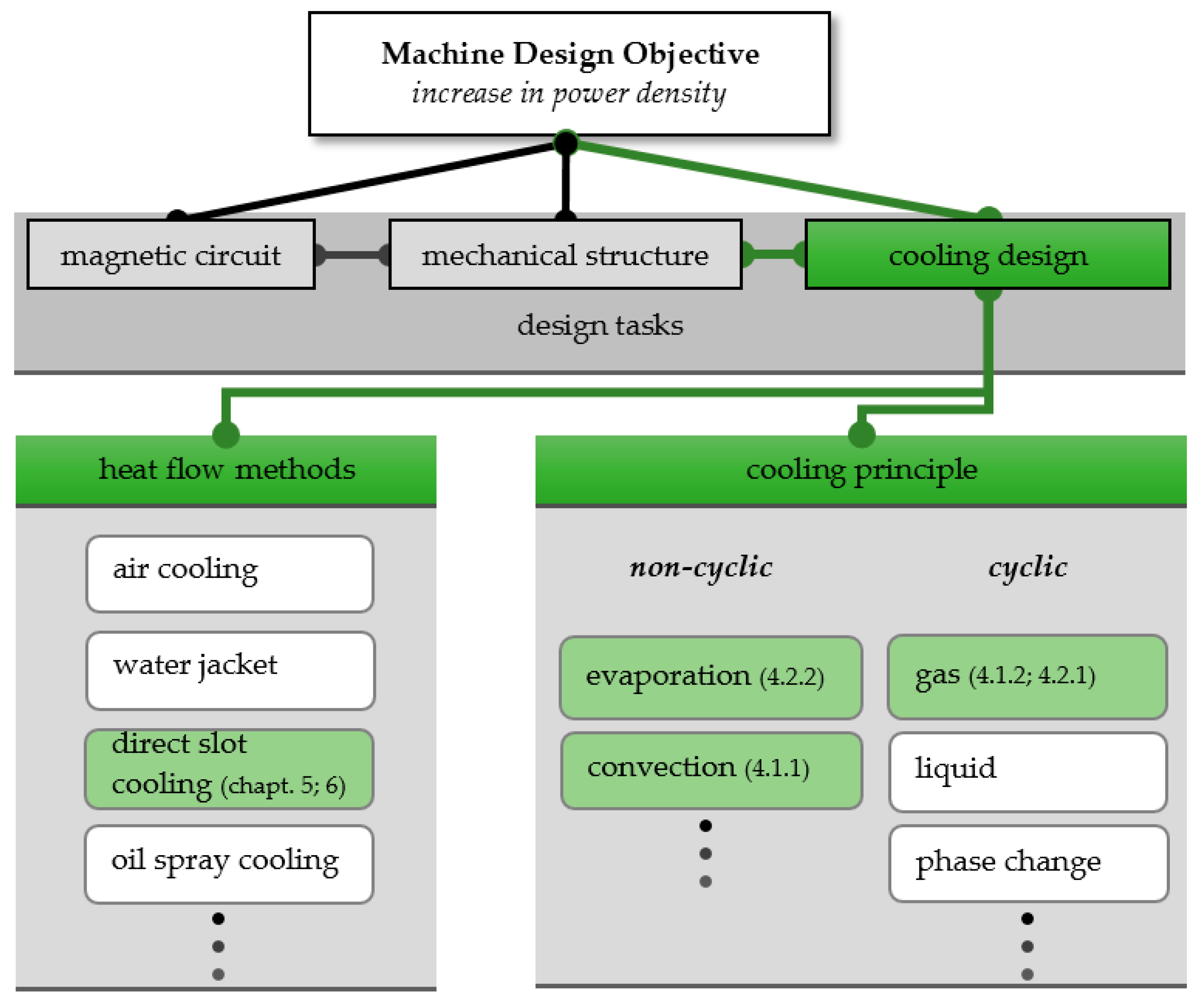
The scope of this paper is illustrated in Figure 1 as the green path. In this case, the focus is on studying the theoretical potentials of cooling technologies for conventional high-power density machines with one phase fluid cooling applicable to drives of some MW rating for smaller aircrafts or single aisle aircraft. With a new proposal for direct slot cooling, a high potential to improve the cooling system is identified and so this is studied in depth in Section 5. The results will help develop a design strategy for aviation drives.

2. Holistic Requirements on Machine Design for Aviation Application

The operation profile of a commercial aircraft (mission profile) can be reduced to some worst-case scenarios the drive has to deal with. In Reference [8], some references are given to the operation modes of an aircraft. It comprises the take-off with overload power at ground pressure and temperature, the subsequent climb flight with nominal power and decreasing ambient temperature, the cruising at high altitude with reduced power and very low ambient temperature of −40 to −60 °C, and the approach for landing with reduced power and increasing ambient temperature. During landing, an electrical drive offers the favorable feature of a short response time if a touch-and-go procedure is required.
The ground temperature can vary from −30 to −40 °C (Alaska, North Canada, Greenland) to +40 °C (Dubai, Caracas) or more. For conventional planes, an ambient temperature of 40 °C requires a significant reduction of take-off weight or a longer runway. That is why we defined 40 °C as the reference temperature for this study.
From the mission profile, a worst-case scenario for the electrical drive and the cooling system can be derived. Take off with overload power from an airport in a tropical region with usually high ambient temperatures can be derived, which the cooling system has to handle reliably. The temperature in the machine windings must be controlled and monitored to ensure a safe climb flight. To illustrate the study conducted in this scenario, we referred to an exemplary small-size aircraft with two 1 MW engines. Regarding efficiency, 96% are assumed to be a realistic value, so losses of 40 kW per engine have to be transferred to the ambient temperature.

3. General Considerations for Machine Design

3.1. Electromagnetic Aspects

When designing a low weight machine, flux density and current density have to be balanced properly [9]. With a conventional non-superconducting design, a flux density in the air gap of 1.0 to 1.2 T may be achieved while the current density is limited by the copper losses. With higher losses, a smaller slot height and shorter teeth, respectively, are possible, which contributes to a reduced weight. The weight of the yoke iron is dominated by the saturation of the iron material, so iron cobalt material with saturation flux density of 2.4 T and a high filling factor of the lamination will be the best but most expensive choice. To achieve a low weight design, small pole pitches are a favorable approach, which require higher feeding frequencies that are limited by the iron losses and the eddy current losses in the winding [10].

3.2. Temperature Dependency of Loss Occurrence

The copper losses, moreover, additionally depend on the temperature, and achieve a low operating temperature by low cooling fluid temperatures, which reduces the losses and increases efficiency significantly. Therefore, the utilization of the low ambient temperature at higher altitudes is very appealing. On the other hand, the maximum hot spot temperature of the winding is limited by the insulation system. Standard is class H insulation [11] with a maximum winding temperature of 180 °C. A class R insulation (220 °C) may be possible, but experience shows that the thermal conductivity is smaller than insulation with class H materials, so the achievable increase of current density is small or zero.
In the first step, the influence of winding temperature on the losses is studied for a copper winding and aluminum winding with the same resistance at a reference temperature of 25 °C. Additionally, the choice of winding material has an influence on the weight of the machine, which is a key figure in aviation. Exemplary dimensions of slot and slot pitch are used (Table 1), which may fit to a 1 MW machine. A typical slot filling factor of 45%, as it may occur with a stranded wire winding, was used.
The temperature dependency for the winding resistance is calculated by the equation below.
R w = R 20 ( 1 + α C u ( T w T b ) ) with   α C u = 4.3 · 10 3 1 K ,   α A l = 4 · 10 3 1 K
R20: Resistance at 20 °C. Tw: Winding temperature. Tb: Reference temperature.
Assuming an average winding temperature of 155 °C [11] and a coolant temperature of 60 °C, a typical temperature drops of 95 °C for conventional machines, e.g., with water jacket cooling is obtained. Reducing the coolant temperature to lower values while keeping the temperature drop constant influences the resistance and the winding losses. Figure 2 depicts the losses related to a winding temperature of 25 °C for a copper winding (dPv) and an aluminium winding (dPvAl).
Figure 2 shows a yield of 35% of losses if the winding temperature is reduced from 155 °C to 25 °C respective of a coolant temperature of −70°C. The yield of an Al-winding is slightly smaller with 34%.
The precondition of the same resistance at reference temperature requires higher slots for the aluminum winding and an increase of the weight of the teeth. By calculating the weight of the slot pitch (increased aluminum volume and the weight of the higher teeth), it is asserted that the machine with aluminum winding will be heavier than with copper winding. There is also a strong dependency on the slot filling factor showing that an increase of the slot filling factor to 61% for both windings is necessary to achieve the same weight of copper winding and aluminum winding. The influence of the yoke on the weight is neglected in this case but will sharpen the disadvantage of aluminum winding because, with higher teeth, the outer radius of the yoke will increase.

4. Evaluation and Analysis of Cooling Methods

Traditional cooling methods for electrical machines of high power density as water jacket cooling, oil cooling, direct conductor cooling with hydrogen, or water are well known and do not need further discussion [12,13,14,15]. The two latter systems are used for turbo generators with ratings of PN > 200 MW up to 1 GW and require complicated and heavy equipment for heat exchangers, sealing and desalinization plants, or very advanced and expensive technologies, as described in Reference [6].
Using low temperatures and dry air at high altitudes for the cooling of the drives allows the design of a lightweight cooling system. However, the challenge is on ground in a hot and humid region during the start and climbing phase. This requires dimensioning of the cooling system for the worst-case scenario or additional boost systems, which provide the necessary cooling capacity on ground. Both approaches will increase the weight of the cooling system. Furthermore, several possibilities are compared to maintain a low winding temperature even at take-off and climb flight or at least to provide an additional cooling effect (boosting of the cooling system). All boost systems support the cooling in addition to a continuously operating cooling circuit, which requires further heat exchangers or a separate cooling circuit, which requires further heat exchangers or separate cooling channels in the electrical machine [15].

4.1. Cooling with Cold Gas

4.1.1. Cold Gas from a Reservoir (Open Brayton Cycle)

This method is a mere boost system. If a reservoir of compressed gas, e.g., dry air that is expanded by a cryogenic turbine is assumed, the cool gas can be used to remove the losses from the electrical machine on a low temperature level. A calculation of this process considering electrical losses of 40 kW, a critical phase during starting and climbing of 15 min and a heating of the cooling gas while passing the electrical machine or a heat exchanger of 10 K shows a mass flow of nearly 4 kg/sec of air requiring a high mass of air to be stored in the reservoir. This is due to the low thermal capacity of air. Therefore, such a system is not suitable for aviation.

4.1.2. Cold Gas from a Compressor Expander Unit

Instead of employing a heavy reservoir of compressed air, an improved approach could use an on-board compressor, isobaric cooling, and expansion by a turbine to achieve a low temperature for the cooling air (Figure 3).
This system can be applied for reducing the cooling fluid temperature during the start procedure (boosting). However, continuous service may be conceivable.
The conducted studies showed that a two-stage compression with the intercooler could be a viable approach. The power output of the turbine could cover a part of the necessary compressor power, so turbine and one compressor are on the same shaft with an electrical motor-generator unit between them (compander). The sketch of an h-s-chart of the process is given in Figure 4.
The evaluation of the real h-s chart [16,17] results in the values of Table 2. As a boundary condition for this calculation, improved efficiencies ηis = 0.8 of the turbo machine equipment and a heating of the cooling air in the machine of 30 K to reduce mass flow and power consumption are assumed. Additionally, the calculation was executed presuming dry air as the first approach to evaluate the potential of the process.
In the second stage designed as a compander, the shaft power of the turbine reduces the power consumption of the compressor. Therefore, the overall consumed process power is 170 kW. Given an efficiency of the electrical machines of ηel = 0.95, we need electrical power of Pel = 180 kW.
This example indicates the mass flow of cooling air and the temperature rise in the electrical machine as key figures in such a system. The output temperature of 0 °C came by chance but points to a very critical fact. To design a realistic system, we have to take into account the humidity of the air, which can be very high (90%) at a place like Singapore. With humid air, a different h-s chart is obtained and different enthalpy values, so the figures calculated in this case for dry air have to be seen as preliminary values for the first estimation. However, especially in the turbine condensate or ice forming has to be avoided, which could be a killing factor for this process. That is why an additional refrigerant air dryer is likely necessary, which adds additional weight to the system. The cooling system sketched in this case not only charges the energy balance of the electrical on-board system but also has an impact on the mass balance of the drive system, which is the most important value for aviation. The additional weight of this air conditioning system has to be compensated by a weight reduction of the fan drive or other advantages in the aircraft power system.
Accounting for a light weight construction of the turbo machine equipment including electric drive of approximately 0.15 to 0.25 kg/kW, 58 to 96 kg additional weight has to be taken into consideration. For cooler and piping weight, we can estimate an analogy to automotive components, which is another 10%. Furthermore, the weight of the refrigerant air dryer has to be added, which also has to be a special aircraft lightweight device. Therefore, the reduced cooling air temperature should at least allow a weight reduction in the electrical machine of approximately 64 to 106 kg or other advantages for the drive that justify the effort for the cooling system. Compared with an electrical machine including inverter for 1 MW rated power and 5 to 7 kW/kg power to weight ratio drive weight of 200 to 143 kg is obtained, which again illustrates the challenges for designing the cooling system.

4.2. Cooling by Using the Phase Change Enthalpy

4.2.1. Cooling with Reversed Rankine Cycle

In this case, a cooling process with low boiling fluids has to be established, which enables the removal of losses at overload in an extreme ambient situation. However, the application as additional chiller for optimization of a continuous working cooling system is conceivable. Due to the anticipated weight of such systems, the considerations were concentrated on the chiller option for supporting a main cooling system. That is why the amount of losses to be handled was reduced to 10 kW.
The reversed Rankine process is well known from refrigerators and other cooling devices. Cooling fluid fluorocarbons, which are chemically-stable, non-toxic, non-corrosive, and not harmful for the atmospheric ozone layer, may be used. The fluid has to have a very low boiling temperature at 1 bar and critical temperature above 45 °C. Several chemical compositions of these fluids are available on the market. The calculations done in this study are conducted with R 507A (ts = −47.1 °C, tc = 70.62 °C) [18], which may be most suitable for aviation with respect to the safety aspects.
In the first step, a simple cooling machine was studied, which is similar to the ones used in refrigerators or industrial cooling processes. The structure is given in the scheme of Figure 5. For a better understanding, the process is depicted in the p-h diagram of Figure 6 [19].
As the efficiency of the compressor approaches nearly zero at −70 °C, the operating temperature at the evaporator was lifted to −60 °C with the consequence of a smaller yield of losses.
Given an ambient temperature of +40 °C as in the load case discussed above, the cooling machine has to operate at full power. Table 3 shows exemplary data for this load case assuming that approximately 10 kW of losses have to be transferred to the ambient environment. This operating point is, in fact, rather unfavorable because the isentropic efficiency of the compressor is with ηis = 0.423 very small. If the removed losses Pv of the electrical machine are related to the power consumption of the compressor Pco, the coefficient of power, COP, is obtained.
C O P = P v P C O
Furthermore, we have to keep in mind that the compressor work is transferred to the fluid so the condenser must be dimensioned for the sum of Pv and Pco. The size of the pipes is also important for the weight balance, which cannot be neglected as usual in smaller devices.
From the data in Table 3, it can be concluded that the compressor will be a relative heavy device because the pressure ratio and pressure difference require a piston engine of appropriate size and pressure capability. Industrial compressors of this rating will weigh approximately 1000 kg. Assuming a special light weight development for aircraft yielding one-third of this value, a weight of 300 kg has to be taken into account, which illustrates the challenge for this application.
Studying the compressor power consumption as a function of the evaporator temperature at higher temperatures, a drastic reduction of compressor power and a fairly good rise of COP is observed. Yet, the losses to be removed increase as well (Figure 5).
In Figure 7, the green line shows the saved losses ΔPv in the electrical machine compared to an usual winding temperature of 155 °C.
In the region between −30 to 0 °C, good operating points with moderate compressor power and a reduced pressure ratio are obtained, but the power consumption of the compressor is always higher than the saved losses due to reduced winding temperature. That is why the system efficiency is lower than with a conventional cooling process. This leads to an unrealizable adjustment due to the weight balance. The compressor and the other parts of the cooling cycle will add an additional weight of 300 to 350 kg for an improvement of losses of 4.5 kW in the drive but will charge the on-board power supply with 24 kW power consumption. Clearly, this operating point will be out of the discussion.
Even if an operation point of −20 °C is considered with an improvement of losses of about 2.5 kW, we need a 6-kW compressor designed for a pressure of approximately 16 bar.
For industrial compressors of this size, a weight of approximately 422 kg has been determined. Assuming a special development for aviation requirements, the weight may be reduced to one-third corresponding to 140 kg, which is a real challenge for the propulsion system design.
We also studied improved cooling circuits with two-stage compression and intermediate injection and an internal intercooler, as depicted in Figure 8a,b. Both methods offer a slight improvement of COP but cannot be considered game changers because the principal tendencies remain unchanged.
Using such a system to support a continuously working cooling cycle during the start and climb phase of the flight may be possible. This will require an optimization between compressor power, saved losses, weight of the electrical machine, and weight of the additional components of the cooling circuit with evaporator temperatures between −20 °C and 0 °C and COP values between 2 and 3. This is a task for further investigations.

4.2.2. Boost System with a Water Reservoir

Evaporation enthalpy of water at reduced pressure is employed, as depicted in Figure 9. From the reservoir, water flows to the evaporator working at a pressure of 0.074 bar yielding an evaporation temperature of +40 °C. The evaporation enthalpy is energized by the losses of the electrical machine, which are assumed to be Pv = 40 kW. The evaporation is an isobaric process and the compressor unit releases the steam to the ambient at 1 bar.
The required evaporation heat ΔQv is shown below [20].
0.2 bar2357.9 kJ/kg
0.074 bar2406 kJ/kg
For a take-off and climb time of 15 min, the loss energy equates to 36,000.0 kWs. This gives the required mass of water Mw = Pv⋅t/ΔQv.
60 °C0.2 bar15.26 kg
40 °C0.074 bar14.96 kg
Providing a water reservoir with 20 kg content should allow for a safe starting and climbing procedure to altitudes with a lower temperature level.
An open question is the design of the compressor unit. The pressure ratio will be 1:5 at 60 °C or 1:13 at 40 °C. For a boost process, the temperature level of 40 °C is the more attractive one because the temperature level of the main cooling circuit is often at 60 °C. The lowest weight can be expected for a turbo-compressor unit, which has to contain two or three stages. Even for a radial compressor, the challenge will be the design of the wheel for this small mass flow of 16.7 g/sec. Since 1 kg of water has a steam volume of 1.673 m3 at 1 bar, the volume flow V ˙ will be 100.4 m3/h at 1 bar.
Moreover, a rotary vane pump or a scroll pump was considered because it has no problems regarding low pressure, but the steam capacity of these pumps is very limited, which requires an extreme oversizing for this purpose with a very high weight of several hundred kilograms [21].
Considering a compressor unit, the problem of the steam temperature at the steam release is important. From the h-s chart of water [22], a steam temperature of 385 °C for a one-stage process is concluded without intercooling. Therefore, there will be no condensate forming. The enthalpy difference assuming an isentropic efficiency of 0.8 would be 670 kJ /kg yielding a power consumption of h · m . = 11.2   kW . With an electrical efficiency of ηel = 0.9, this gives a compressor power of 12.5 kW optimizable by intercooling after the first and second stage.
Estimating a specific weight of the compressor unit of 0.15 to 0.25 kg/kW in lightweight design, an additional weight of 1.9 to 3.1 kg is obtained. In summary, the determined features of such a boost system could be interesting for aviation applications in a thermal critical environment.

5. Methodical Improvement of the Thermal Conductivity Path in the Electrical Machine

The discussion of cooling systems were based on the assumption of an electrical machine with conventional cooling fluid jacket as used in high power density constructions in industry or automotive drives.
This implicates a certain temperature drop between cooling fluid and winding, which was set in these considerations to approximately 80 to 95 K. As an alternative design, machines with cooling channels placed between the copper conductors in the slots are studied (direct slot cooling). 
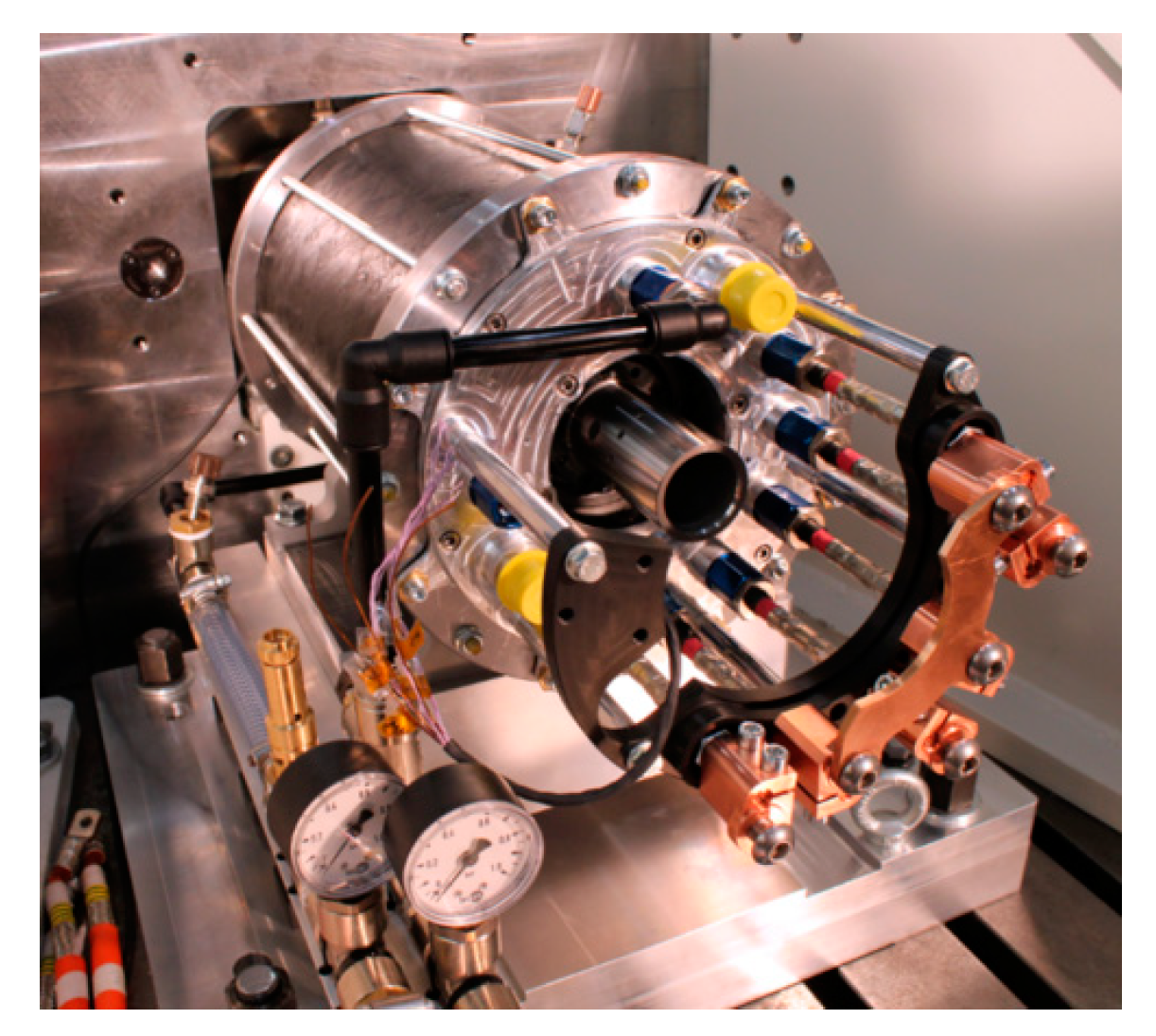
Figure 10 shows a tested direct slot cooling prototype machine at the IMAB.
Depending on the achieved current density, this may increase the weight of the teeth and yoke, but the losses are then removed where they arise and high current densities under overload and steady state operation can be achieved with a decreased temperature rise in the winding, which allows a low weight design. To overcome the drawbacks of the intra winding cooling mentioned in Reference [5], all cooling channels are hydraulically in parallel, which reduces the pressure drop significantly. Each slot has at least two or more cooling channels made from thin-walled plastic tubes. To avoid freezing of the cooling fluid at low ambient temperatures, it is advantageous to use a chemical inert fluid with low viscosity even at low temperatures but also with high temperature capability. Fluids on a polysiloxane basis seem to be a good choice [22]. The current density in the winding is considered to be an optimizable quantity, which can be balanced between machine weight, efficiency, and cooling system weight.
With respect to the probable feeding frequency of 400 to 700 Hz, stranded wires as conductors are a prerequisite. If the machine is appropriately designed, no reduced cooling fluid temperatures are necessary, but the operating temperature of the coolant can be chosen at +60 °C to +90 °C with the option of utilizing the low ambient temperatures at cruising altitudes to reduce losses. In addition, a coupling of this cooling circuit with a chiller operating with a reversed Rankine cycle or an additional boost system, as described in Section 4.2.2, is possible and may support an optimization in critical environments.
Typical values for the polysiloxane thermo oil [22] are a thermal capacity of 1.75 kJ/(kgK) at 50 °C and 1.87 kJ/(kgK) at 100 °C as well as fairly low viscosity of 1.19 mPa⋅s at 50 °C, which is close to water. The critical temperature is 350 °C and utilizing these fluids at a temperature range from −82 °C up to 200 °C can be covered, which is more than the range of usual water-glycol mixtures. Thus, no problems even at high cruising altitudes are expected. The fluids are non-toxic and electrically insulating. The environmental impact if accidentally released at high altitudes needs more in-depth studies.
The simplest construction of the electrical machine for this case is a separation of rotor and stator by an air gap sleeve. Consequently, the winding overhangs are immersed in the cooling fluid that is circulating through the overhang spaces, the open slot channels, and a heat exchanger. The classical problem of an air gap sleeve is production of additional eddy current losses and a braking torque if it is made from electrical conducting material. These losses can put severe limits to the machine design. By employing modern construction materials, non-conducting air gap sleeves are possible currently so that this problem can be solved.
A design alternative avoiding the air gap sleeve problems could be distribution channels in both overhang spaces, which are connected with the cooling channels in the slots. This requires an appropriate choice of insulating thermoplastic material and welding technologies but will pose no greater problems to the production process.
A third alternative could be the introduction of heat pipes instead of the cooling channels. The heat exchanger will then be integrated into the overhang spaces. The advantage would be a hermetically sealed cooling system with no risk of leakage. The challenge is the choice of the material. The preferred material for heat pipes is mostly copper that cannot be used in the slot area because of the eddy current losses. Other less conducting materials for the heat pipe may exhibit the risk of hydrogen forming that will block the condensing zone of the pipes.
The calculation of the temperatures of winding and iron can be done with analytical (equivalent heat transfer network) or with numerical methods (finite element method). The method of thermal equivalent networks is well established and described in literature. One of the oldest sources found is reference [
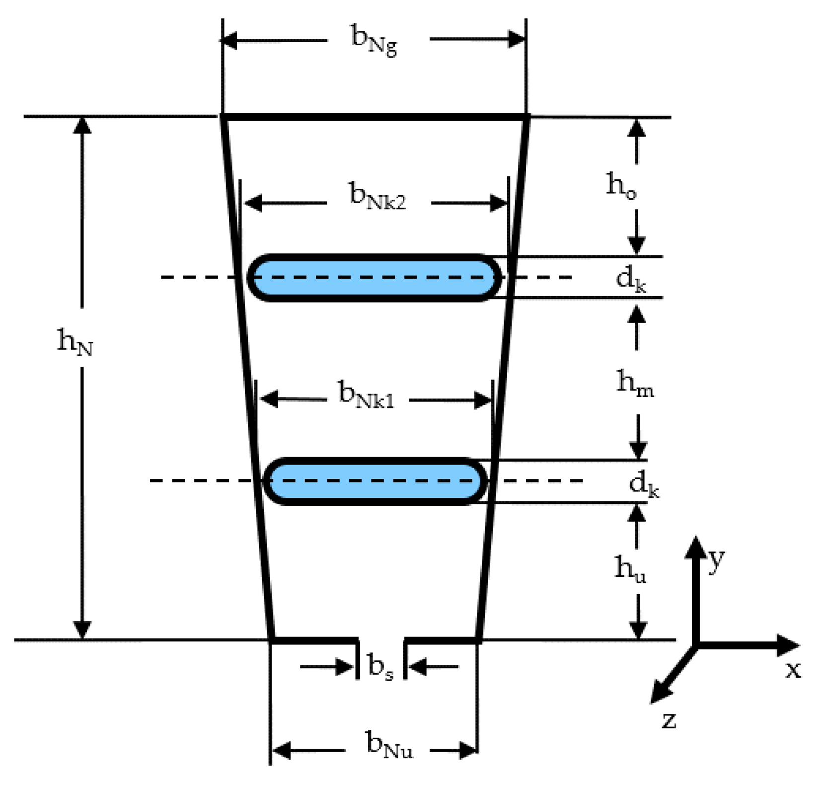
23] dating from 1967. The problem for any calculation method is posed by a sufficient accurate database for the materials used in the machine and an additional challenge for the designer comes with the production experiences. For the first theoretical study, the temperature distribution in an exemplary slot with the dimensions according to Figure 11 was calculated with analytical and numerical methods as well. The used thermal data are given in Table 4.
The thermal conductivity of the winding was calculated from the data of a mixture of copper and impregnating resin in all three dimensions. By using this, the winding is represented as a homogenous region.
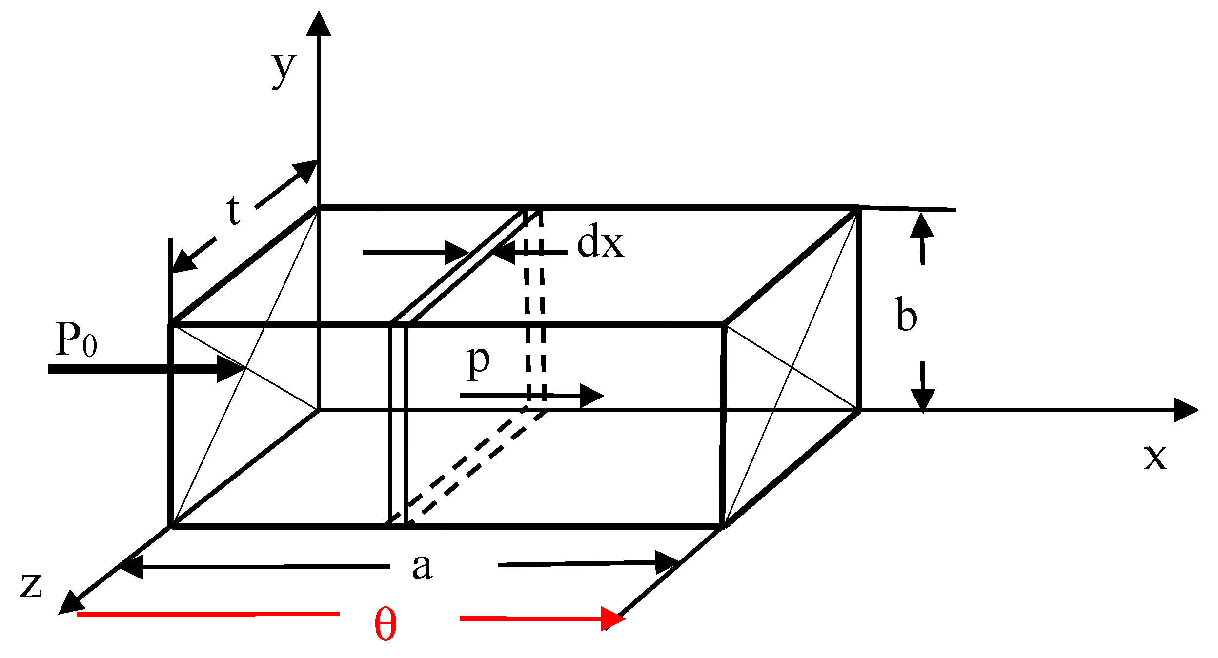
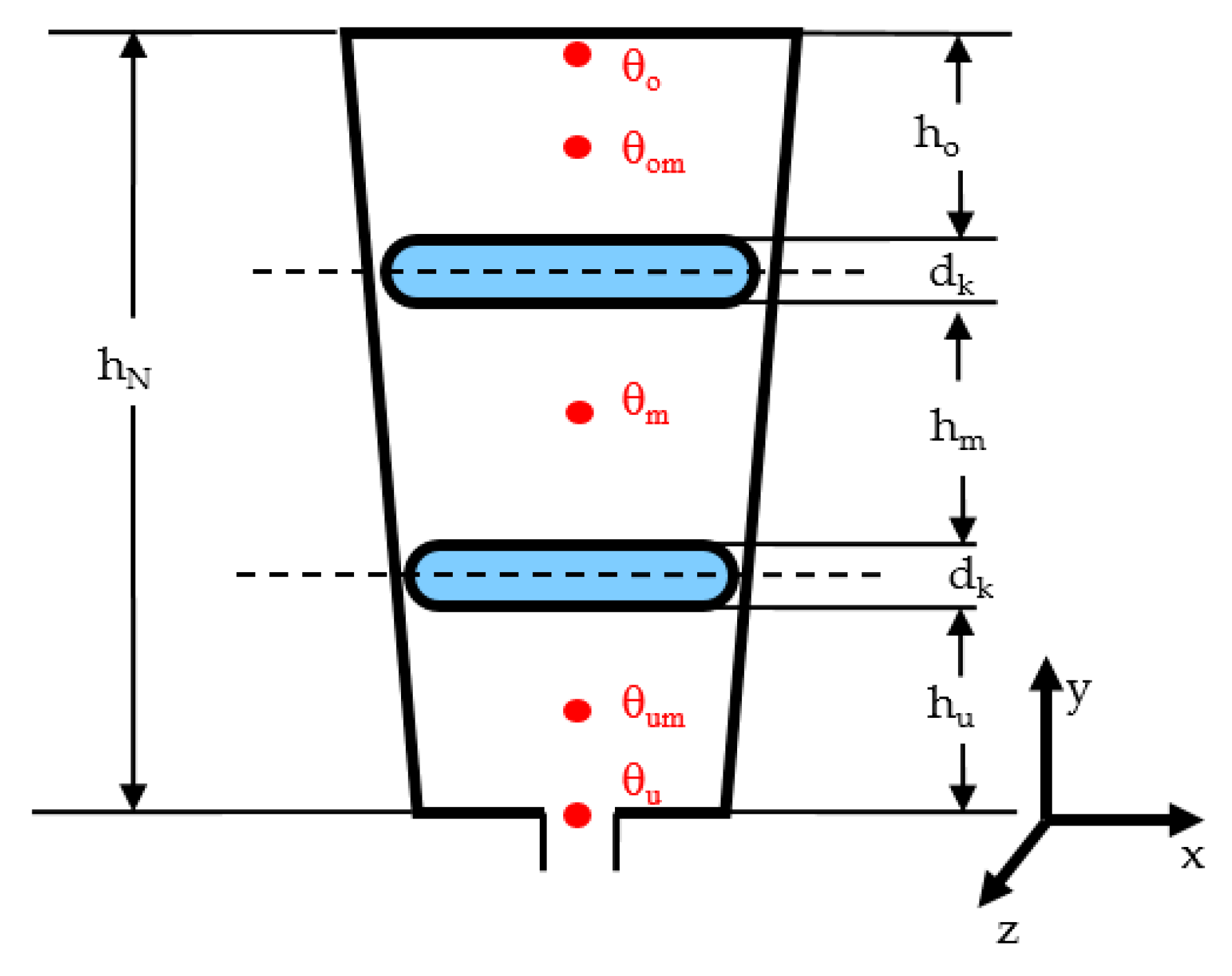
To improve the accuracy of the analytical calculation especially in regions possessing high current densities, a new calculation model for the regions with distributed losses was introduced, as shown in Figure 12.
The temperature drop θ in the region of Figure 12 is composed from the temperature drop due to the external load P0 and the inner loss density p.
P ( x ) = P 0 + p t b x ,   d θ = P ( x ) d x λ x t b
θ = 0 a P ( x ) d x λ x t b = 1 λ x t b 0 a ( P 0 + p t b x ) d x = P 0 a λ x t b + p t b a 2 2 λ x t b = θ 0 + θ v with   R 0 = a λ x t b   and   P v = p t b a
θ = P 0 R 0 + P v R 0 2
R = θ P 0 + P v = R 0 2 2 + P v P 0 1 + P v P 0
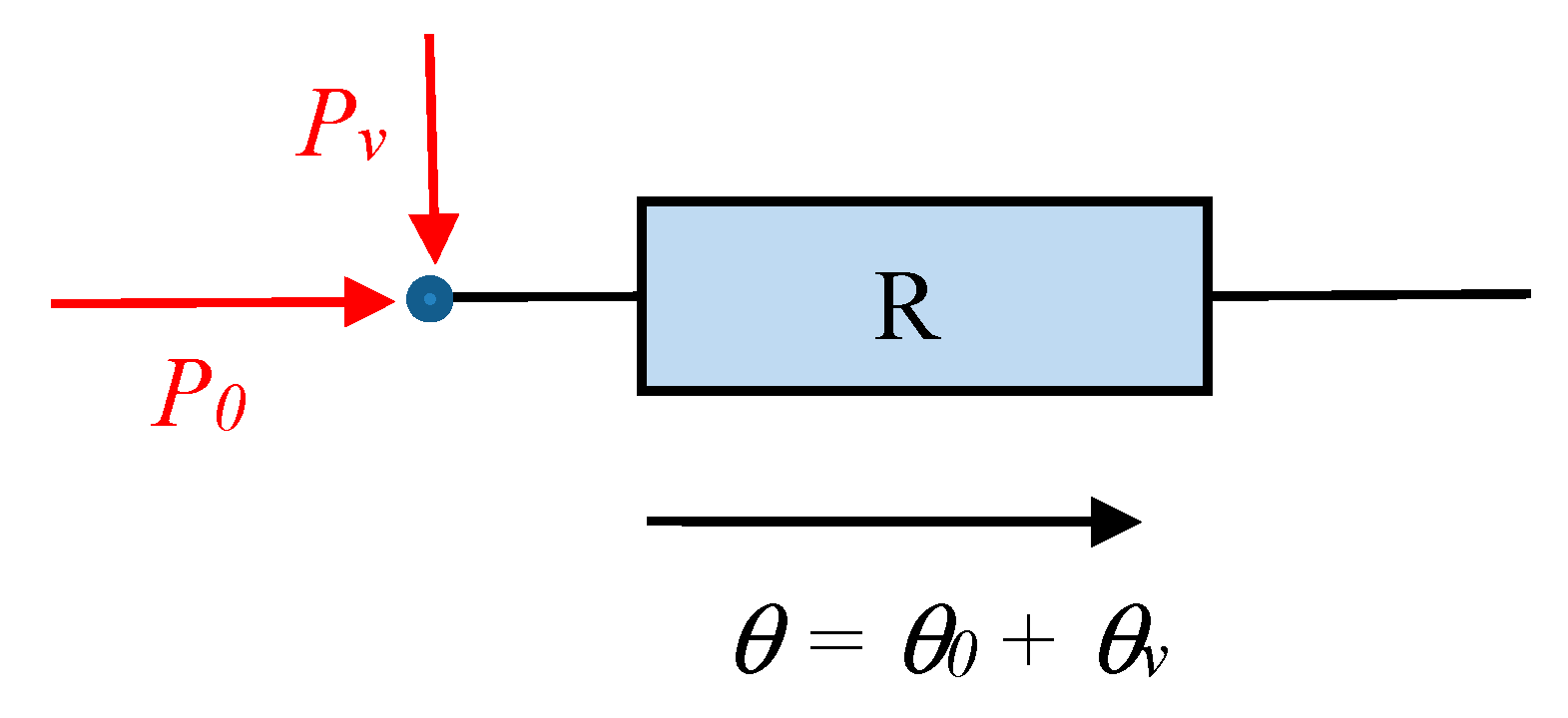
The network element of Figure 13 gives a representation of a region with distributed losses. The size of the thermal resistance R now depends on the relation of the distributed losses and the external losses.
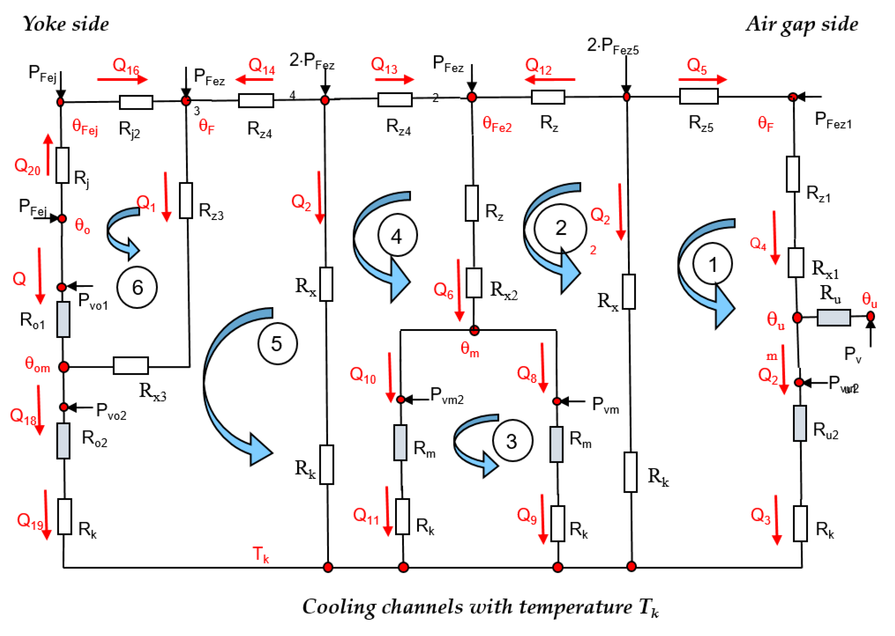
Distributed losses are observed in the winding and in the iron as well. To reduce the calculation effort, only the losses in the winding were calculated as distributed losses—elements with light blue filling in Figure 14—while the losses in the iron were represented with conventional lumped parameters. Due to the symmetry of the problem, it is sufficient to establish the thermal equivalent network for half of a slot in the x-direction with a symmetry line in the slot middle. All calculations were restricted to a 2-D-Heat flow problem. A heat transfer in the third dimension to the winding overhangs is neglected, so all calculations are on the safe side.
The thermal transfer network of Figure 14, therefore, represents the implemented calculation model for the analytical calculation. For a more efficient mathematical handling, the network was redrawn. It is assumed that all heat flows are conducted to the cooling channels on the temperature level Tk. The heat flows in the branches of the network are denoted as Q and the distributed losses are named Pv. The resistance of the channel walls is named Rk. The iron losses are denoted as PFez for the tooth and PFej for the yoke sections, respectively.
The system of linear equations derived from the lumped parameter network (six meshes, 22 branches) poses no major problems from the mathematical point of view. The advantage of the lumped parameter network is that it allows the fast and simple calculation of changes in the calculation model and an easy representation of 3-D heat flows if the model is extended by a heat flow to the end windings.

Verification of Analytical Calculations

To verify the results, a numerical finite element calculation model was established with ANSYS software. The hot spots for the comparison of both calculation approaches are given in Figure 15.
Table 5 displays the calculated values of the temperature drops at the hot spots of the slot resulting from numerical and analytical calculation. 
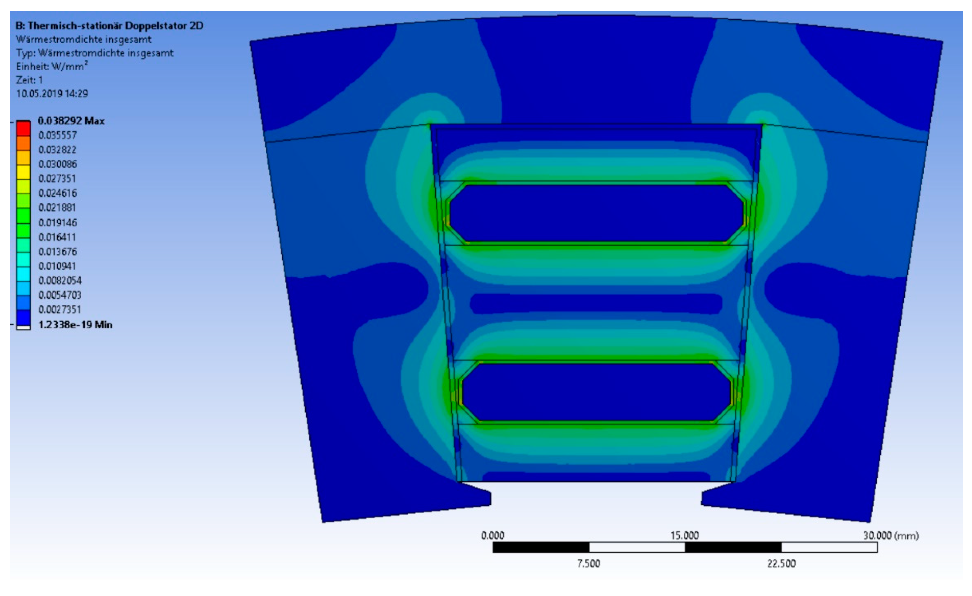
Figure 16 shows the density of the heat flow within a single slot pitch. The main heat flow that goes directly to the cooling channels were assumed to be at a constant temperature of 80 °C. Clearly, there is also a heat flow around the cooling channel edges over the tooth iron, which were not represented in the analytical calculation. 
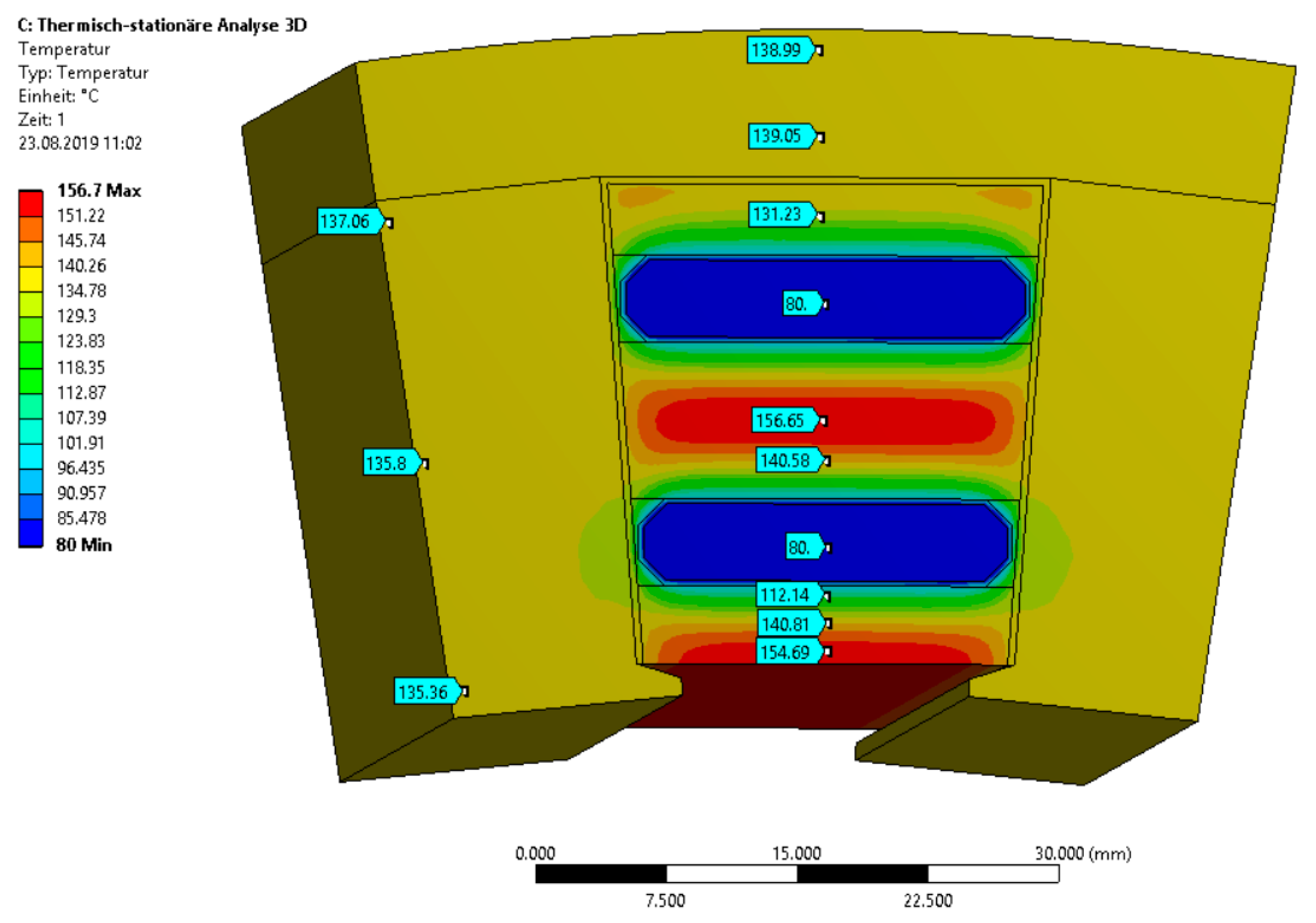
Figure 17 shows the temperature values within a slot pitch (current density of 15 A/mm2, steady state, copper filling factor of 70%).
The obtained accuracy of the analytical calculation is satisfying the usual uncertainty of the material database. A comparatively high temperature drop in the walls of the cooling channels of 17 K can be observed. In this case, we can identify an optimization potential by choice of material and wall thickness.
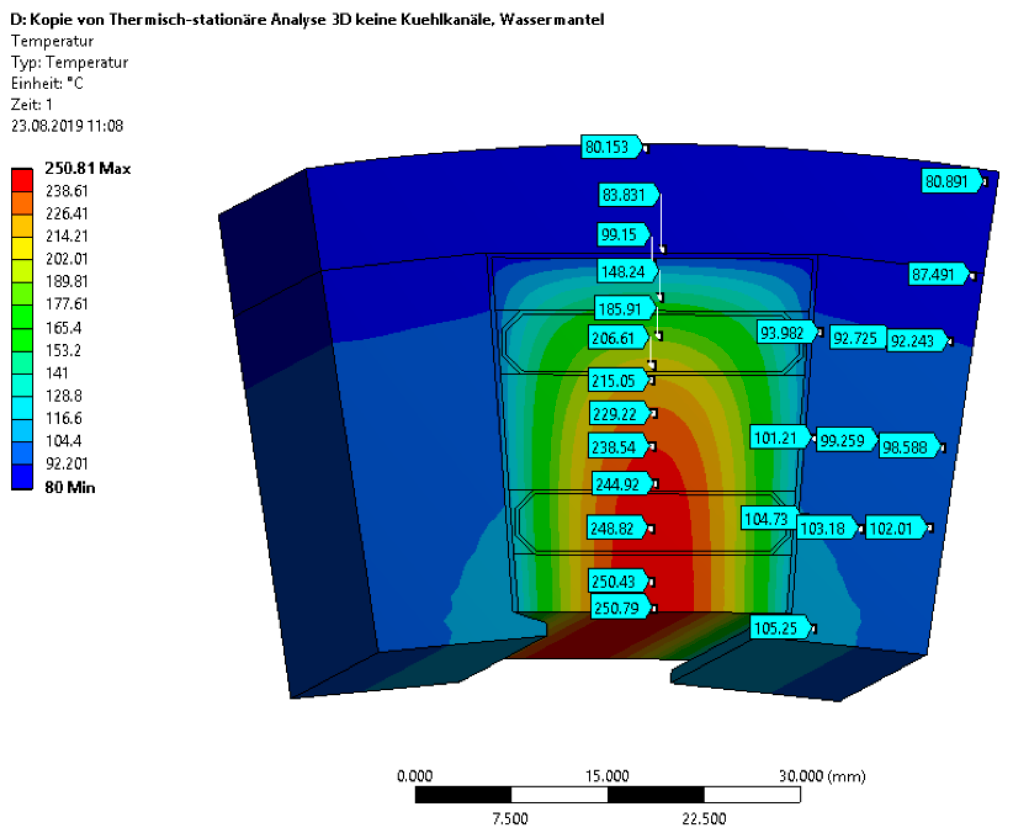
For a further comparison, a calculation for a machine with classical water jacket cooling was made under the same assumptions of the thermal properties as before (Figure 18). The cooling channels are replaced by copper winding. To achieve the same current loading in the slot, the current density was reduced to 9 A/mm2. This gives significantly reduced losses but, nevertheless, the calculation shows a temperature rise of 170 K respective of a difference to direct slot cooling of 94 K.
The direct slot cooling exhibits an impressive potential to optimize the current sheet, force density, temperature distribution, and the weight of the machine. Due to the identified potential, experimental investigations are planned in the next steps of the project.

6. Calculation Results on Heat Transfer Channel Wall—Cooling Fluid

Three major temperature drops will dominate the cooling system design of an electric aviation drive.
  • Temperature drop between winding and cooling channel wall. This can be minimized by direct slot cooling.
  • Temperature drop between cooling channel wall and coolant (discussed in this section).
  • Temperature drop between coolant fluid and ambient environment depending on the design of the heat exchanger. Highly effective heat exchangers for aviation will be a topic of further studies.
To calculate the heat transfer from the cooling channel wall to the cooling fluid, one has to solve the hydraulic equations of the cooling system to receive the pressure drop in the cooling channel and the fluid velocity. By estimating the pressure difference in the cooling channel from experience values, a preliminary study of possible problems can be conducted even in an early design stage. The calculations were performed by applying water glycol and a polysiloxane fluid [22]. Starting values and fluid properties for the calculation are shown in Table 6 and Table 7.

6.1. Power Balance and Hydraulic Data

Compared with water, the polysiloxane fluid has an inferior thermal conductivity. Therefore, a higher temperature drop should be expected. The necessary volume flow to remove the losses is calculated from the power balance and the allowed temperature rise ΔTk in the cooling fluid.
V ˙ = P v , m a x Δ T k ρ k c p k
In the first step, a pressure difference of Δp = 0.15 bar was assumed.

6.2. Temperature Drop to the Channel Wall and Heating of Cooling Fluid

The temperature drop between the channel wall and fluid is derived from the heat transfer coefficient α, the losses Pv,max, and the surface of channel Aw.
Δ T w = P v , m a x α · A w
For the calculation of α, according to Hausens equation [24], the velocity of the fluid and the Reynolds number are required. Turbulence and large Reynolds numbers are advantageous for a good heat transfer. The calculations were performed for variable channel dimensions with the hydraulic diameter dh. (A: cross section of channel, U: circumference of the channel).
d h = 4 A U
The exemplary construction of Figure 11 shows a hydraulic diameter of 6.5 mm. The Reynolds number results from the velocity v of the fluid for turbulent flow by numerical solving of the nonlinear Blasius equation (νw: Kinematic viscosity, Lk: length of the channel, ρ: Density of the fluid):
a = 0.316 ( v w d h ) 0.25 L k d h Δ p = ρ 2 ( a · v 1.75 + 6 v 2 )
R e   y = v d h v w
The Reynolds numbers for this example are approximate Rey = 104, so turbulent flow can be assumed.
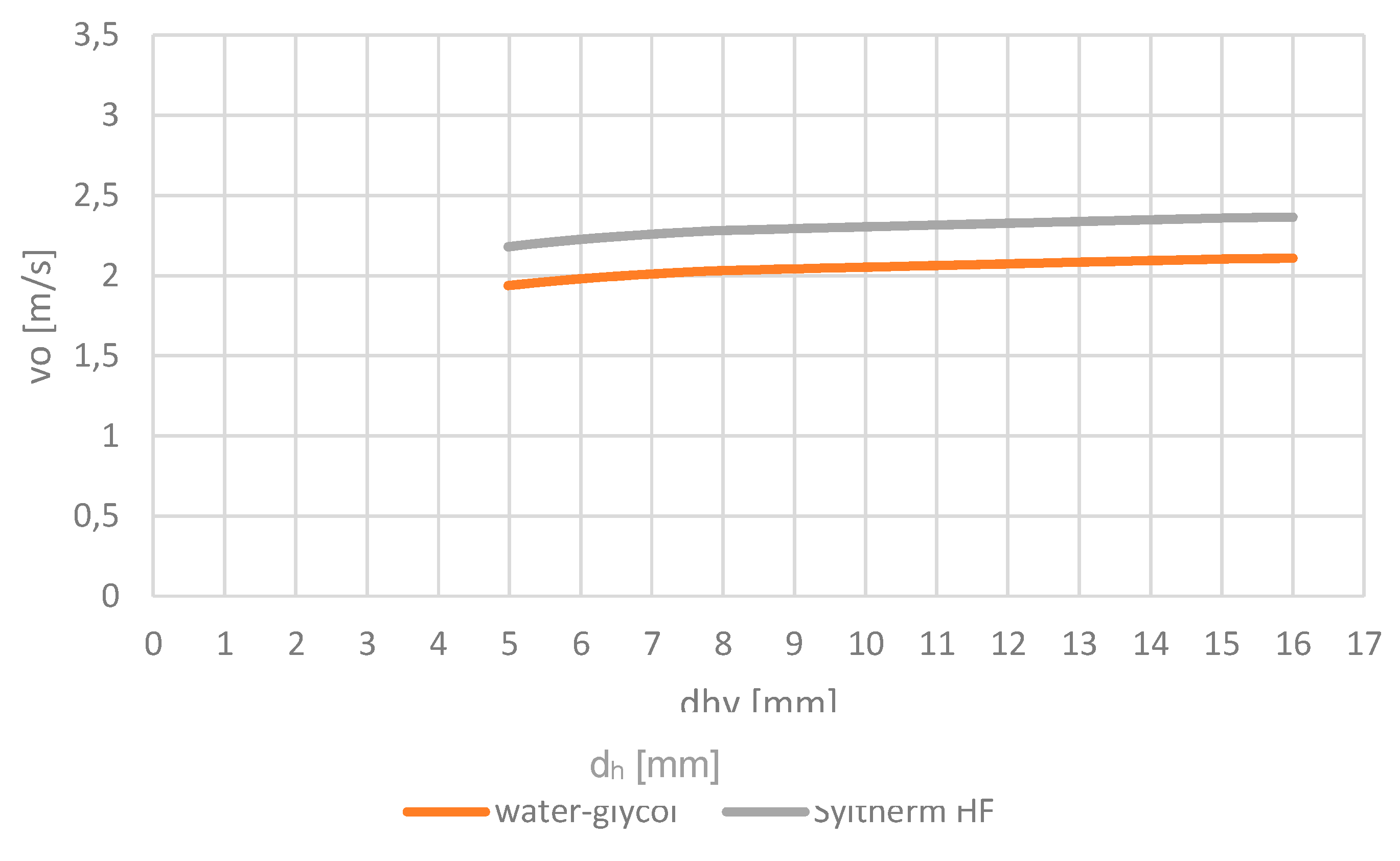
The velocity (Figure 19) is used to calculate the Nusselts number and the heat transfer coefficient α [24] (Pr: Prandtl number, ηw: dynamic Viscosity, λw: Thermal conductivity of fluid, cp: specific heat, K1: Correction factor for the different velocities in the fluid set to 1.1.).
K 1 = 1.1 P r = η w · c p λ w N u = 0.012 [ ( R e   y ) 0.87 280 ] P r 0.4 [ 1 + ( d h L k ) 2 3 ] K 1 α = N u λ w d h
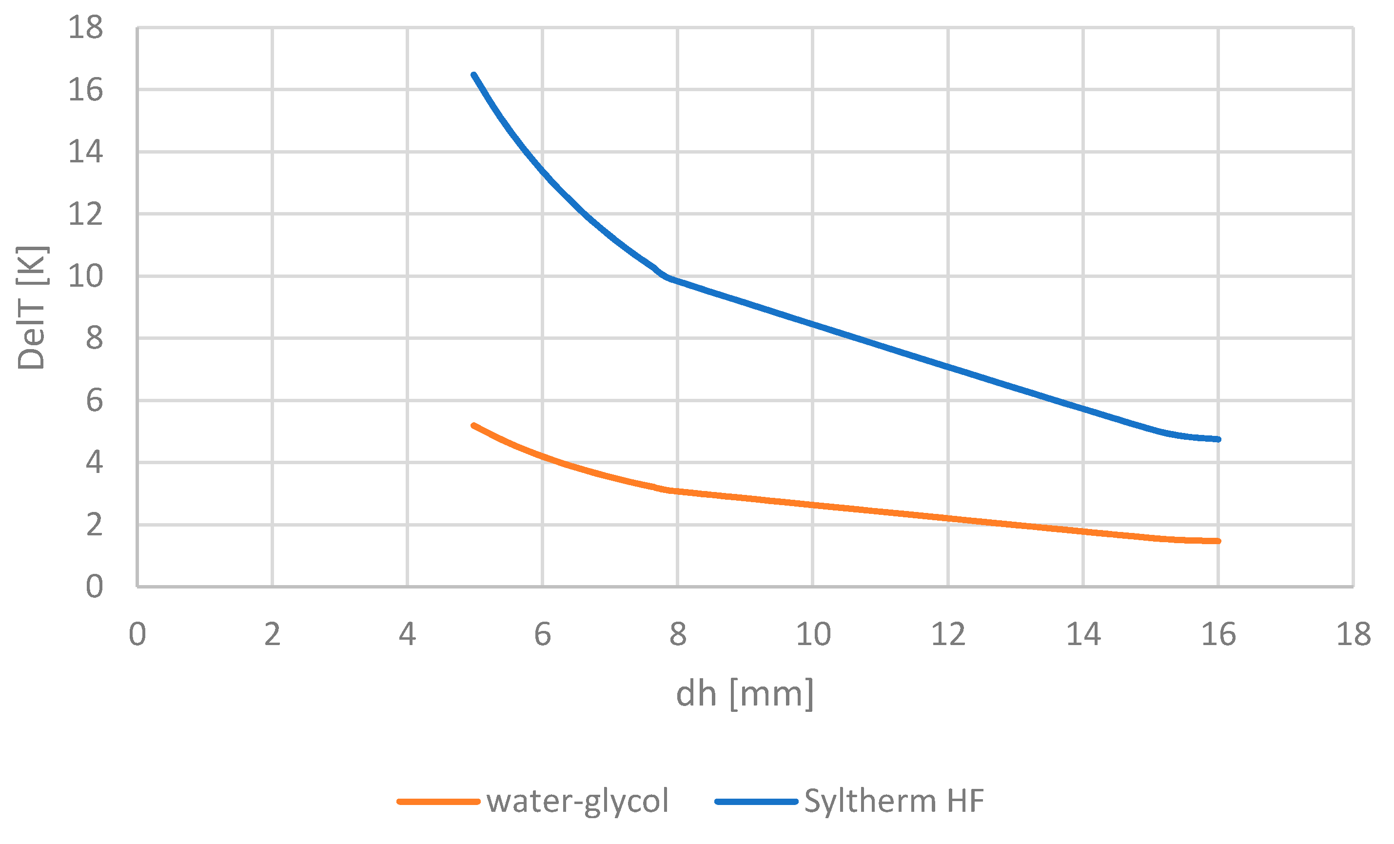
Figure 20 shows that, due to the inferior thermal conductivity of the polysiloxane fluid, we have to assume a much higher temperature difference between the channel wall and fluid than with the water-glycol mixture. The comparatively high temperature drop of 12 K that comes with the polysiloxane fluid has to be taken into account when designing the cooling system.
Furthermore, we can conclude that an increase of the hydraulic diameter or increase of velocity (higher pressure) will have a positive influence on the temperature drop and the heat transfer.
To estimate the power of the pump, the volume flow V ˙ is an important figure. For this example, the required pump power was estimated with 2.1 l/min per channel and 24 slots and an overall pressure drop of 2 bars to approximately 340 W, which will be a good starting point for the system optimization.
When the cooling fluid itself is heated up by the transfer of the machine losses, the temperature rise in the fluid can be calculated, according to Equation (7). Since both fluids possess a relatively high specific heat, the temperature rises by 0.5 to 1.0 K, which is not dominant for the cooling system design.

7. Discussion of Results

In this paper, we studied potentials to reduce the weight of electrical drives for aviation propulsion. Besides the usual design approaches (small pole pitch, high airgap flux density, high current sheet, high speed, and high saturation of lamination), the cooling system is a key component since the temperature in electrical machines is strictly limited by the insulation system. It is very attractive to employ the low temperatures at high cruising altitudes, but the critical phase during an aircraft mission is the take-off and climbing flight especially when taking off at tropical airports exhibiting high ambient temperature and humidity. The outcome is as follows.
  • The use of aluminum as winding material does not offer many advantages regarding weight reduction. Only by means of very high slot filling factors, advantages were identified.
  • Cooling systems taking advantage of the enthalpy of evaporation of low boiling fluids will work in principle but require heavy compressors due to high pressure ratios. The power consumption is always higher than what can be gained from loss reduction due to lower temperatures.
  • The application of lightweight turbomachinery to utilize the low temperatures from a gas expansion process requires additional weight and increased power consumption, and bears the risk of ice forming due to humid air or additional air-drying equipment, which can imply exclusion of such systems.
  • Enhancing the cooling capacity during the thermal critical start and climb phase by a boost device applying the phase change enthalpy of water at reduced pressure seems possible. This is studied in further research activities.
  • The discussed approaches for reducing the temperature of the cooling fluid in the electrical machine below ambient temperature show that this will be possible when taking into account higher losses and increased weight, which have to be compensated by advantages in the design of the drive or a comparable weight reduction. Additionally, some risks were identified, e.g., the problems of humid air—ice forming in the expansion stage—or the impact of the chemical composition of the cooling fluids on the environment. Alternatively, a machine design using cooling channels placed directly amidst the winding conductors was proposed. This reduces the temperature drop between winding and cooling fluid significantly and allows a simple and robust cooling circuit. Exemplary calculations of the temperature distribution underline the superior properties of this approach. As the losses increase with the higher current density, the system efficiency has to be observed carefully during the design process. The option to use the low ambient temperatures at high altitudes to improve the efficiency can be covered by use of polysiloxane-based heat transfer fluids, which offer a temperature range from −82 °C up to 200 °C. This is more than what could be achieved by conventional water-glycol mixtures.
  • The heat transfer to the cooling fluid with its conjoined temperature drop is another investigated issue. Key design figures are the hydraulic diameter of the cooling channels, the thermal conductivity of the cooling fluid, and the velocity in the channels. The polysiloxane-based fluids require higher velocity and pressure due to their low thermal conductivity.
  • The weight of the cooling system directly depends on the losses of the electrical machine and, thus, on the efficiency of machine and power electronics. This important figure has to be taken into account for the machine-design.

8. Conclusions

The results of this study enable the development of a design strategy for future aircraft propulsion drives. While keeping the efficiency of the electrical machine at a high level, a lightweight cooling system will be possible. Direct slot cooling facilitates a low temperature difference between winding and coolant by which the design of an efficient heat exchanger will be made possible. The combination of a light-weight cooling system and a boost system utilizing the evaporation enthalpy of water permits take-off and climb flight even in tropical environments to be covered safely.

Author Contributions

All authors worked on the conceptualization of the paper and on the requirements on machine design for aviation applications. J.H. performed the finite element model and the software validation and W-R.C. investigated and analyzed the different cooling system structures. He also set up the analytical thermal models. M.H. set up the project administration and funding acquisition. All authors revised and approved the final version of the paper.

Funding

DFG—German Research Foundation, Cluster of Excellence SE2A, Sustainable and Energy Efficient Aviation, grant number 2163\1 funded this research. We acknowledge support by the German Research Foundation and the Open Access Publication Funds of the Technische Universität Braunschweig.

Conflicts of Interest

The authors declare no conflict of interest. The funders had no role in the design of the study, in the collection, analyses, or interpretation of data, in the writing of the manuscript, or in the decision to publish the results.

References

  1. Haran, K.S.; Swarn, K.; Tabea, A.; Haran, K.; Rod, B.; Bob, B.; Timothy, H.; Mitsuru, I.; David, L.; James, W.B.; et al. High power density superconducting rotating machines–development status and technology roadmap. Supercond. Sci. Technol. 2017, 30. [Google Scholar] [CrossRef]
  2. Davin, T.; Pelle, J.; Harmand, S.; Yu, R. Experimental study of oil cooling systems for electric motors. Appl. Therm. Eng. 2015, 75, 1–13. [Google Scholar] [CrossRef]
  3. Wheeler, P. Technology for the more and all electric aircraft of the future. In Proceedings of the IEEE International Conference on Automatica (ICA-ACCA), Curico, Chile, 19–21 October 2016. [Google Scholar]
  4. Maalouf, S.; Isikveren, A.; Dumoulin, P.; Tauveron, N. High temperature heat pump for Aircraft engine oil cooling. ARC 2018. [Google Scholar] [CrossRef]
  5. Weustenfeld, T.A.; Bauer-Kugelmann, W.; Menken, J.C.; Strasser, K.; Köhler, J. Heat Flow Rate Based Thermal Management for Electric Vehicles using a Secondary Loop Heating and Cooling System. In Proceedings of the Vehicle Thermal Management Systems Symposium and Exhibition (VTMS), Nottingham, UK, 10–13 May 2015. [Google Scholar]
  6. Deisenroth, D.C.; Ohadi, M. Review-Thermal Management of High-Power Density Electric Motors for Electrification of Aviation and Beyond. Energies 2019, 12, 3594. [Google Scholar] [CrossRef]
  7. Rhebergen, C.; Bilgin, B.; Emadi, A.; Rowan, E.; Lo, J. Enhancement of Electric Motor Thermal Management through Axial Cooling Methods: A Materials Approach. In Proceedings of the 2015 IEEE Energy Conversion Congress and Exposition (ECCE), Montreal, QC, Canada, 20–24 September 2015; pp. 5682–5688. [Google Scholar]
  8. Christie, R.J.; Dubois, A.; Derlaga, J.M. Cooling of Electric Motors Used for Propulsion on SCEPTOR; AIAA Aviationand Aeronautics Forum and Exposition, No. GRC-E-DAA-TN32571; American Institute for Aeronautics and Astronautics, June 2016. Available online: https://ntrs.nasa.gov/search.jsp?R=20170001724 (accessed on 30 November 2019).
  9. Henke, M.; Narjes, G.; Hoffmann, J.; Wohlers, C.; Urbanek, S.; Heister, C.; Steinbrink, J.; Canders, W.-R.; Ponick, B. Challenges and Opportunities of Very Light High-Performance Electric Drives for Aviation. Energies 2018, 11, 344. [Google Scholar] [CrossRef]
  10. Wohlers, C.; Juris, P.; Kabelac, S.; Ponick, B. Design and direct liquid cooling of tooth-coil windings. Electr. Eng. 2018, 100, 2299–2308. [Google Scholar] [CrossRef]
  11. International Electrotechnical Commission Standard IEC 60085:2007, Electrical Insulation—Thermal Evaluation and Designation. Available online: https://webstore.iec.ch/publication/666 (accessed on 30 November 2019).
  12. Lindner, A.; Hahn, I. Practical evaluation of a passive stator cooling concept without thermal stacking. In Proceedings of the IEEE Workshop on Electrical Machines Design, Control and Diagnosis (WEMDCD), Nottingham, UK, 20–21 April 2017. [Google Scholar]
  13. Aprianingsih, N.; Winarta, A.; Ariantara, B.; Putra, N. Thermal performance of Pulsating Heat Pipe on Electric Motor as Cooling Application. E3S Web Conf. 2018, 67, 03035. [Google Scholar] [CrossRef]
  14. Becker, S.; Uffinger, T.; Schlücker, E.; Weiss, S.; Dorr, G. Efficient and Silent Cooling of Electric Drives–Basics, Measurement Techniques and Computational Approaches. In Proceedings of the 2011 Int. Electric Drives Production Conference (EDPC 2011), Nuernberg, Germany, 28–29 September 2011. [Google Scholar]
  15. Ganev, E.D. High-performance electric drives for aerospace more electric architectures Part I—Electric machines. In Proceedings of the IEEE Power Engineering Society General Meeting, Tampa, FL, USA, 24–28 June 2007. [Google Scholar]
  16. Herrmann, S.; Kretzschmar, H.-J.; Gatley, D. Thermodynamic Properties of Real Moist Air, Dry Air, Steam, Water, and Ice (RP-1485). HVACR Res. 2009, 15, 961–986. [Google Scholar] [CrossRef]
  17. Maurer, T. Berechnungsprogramm für feuchte Luft und andere Gas-Dampf Gemische. Handbuch.
  18. Solvay, GmbH. Technische Informationsblätter zu Kältemitteln, Sicherheitsdaten, Umweltdaten. Phys. Eigenschaften 2010, 1. Available online: http://www.reftec.ch/downloads/Solkane_2010.pdf (accessed on 27 September 2019). (In German).
  19. Solkane Software 8.0, Solvay Speciality Chemicals Ltd.: Brussels, Belgium, 2019. Available online: https://www.solvay.com/en(accessed on 30 November 2019).
  20. Faghri, A.; Zhang, Y. Fundamentals of Multiphase Heat Transfer and Flow; Springer: Berlin/Heidelberg, Germany, 2019; ISBN 3030221369. [Google Scholar]
  21. Product Catalogue Pfeiffer Vacuum. Available online: https://www.pfeiffer-vacuum.com/de/ (accessed on September 2019).
  22. Syltherm, H.F. Heat Transfer Fluid, Product Technical Data; DOW Corning Corporation: Midland, MI, USA, 1997. [Google Scholar]
  23. Wiedeman, Kellenberger Konstruktion Elektrischer Maschinen; Springer: Berlin/Heidelberg, Germany, 1967. (In German)
  24. VDI Wärmeatlas, 11th ed.; VDI Publishing House: Düsseldorf, Germany, 2013.
Figure 1. Methodical design process related to paper structure (green).
Energies 12 04579 g001
Figure 2. Relative losses versus average winding temperature Tw. Reference temperature of 25 °C.
Energies 12 04579 g002
Figure 3. Two-stage compression with the intercooler.
Energies 12 04579 g003
Figure 4. Sketch of the process of Figure 3 in the h-s chart.
Energies 12 04579 g004
Figure 5. Standard cooling machine with expansion by a throttle valve. (1–2 Compression of steam, polytropic, 2–3 Heat losses in the piping, isobaric, 3–4 Heat transfer to the ambient with condensation, isobaric, 4–5 Pressure reduction by throttle valve, nearly isenthalpic, 5–6 Vaporization in the evaporator, isobaric).
Energies 12 04579 g005
Figure 6. p-h chart of the standard cooling circuit (11 kW from −30 °C to +40 °C, R 507).
Energies 12 04579 g006
Figure 7. Transferred power Pv and compressor power Pco over the cooling fluid temperature.
Energies 12 04579 g007
Figure 8. (a) Cooling circuit with two-stage compression and intermediate injection. (b) Cooling circuit with the internal intercooler.
Energies 12 04579 g008
Figure 9. Boost system with the water reservoir and the principal sketch.
Energies 12 04579 g009
Figure 10. Testbed setup at the institute IMAB.
Energies 12 04579 g010
Figure 11. Stator slot with two distributed cooling channels for direct slot cooling (exemplary data: hN = 28 mm, bNg = 26 mm, bNu = 22 mm, dk = 5 mm).
Energies 12 04579 g011
Figure 12. Region with distributed loss density p and external heat flow P0.
Energies 12 04579 g012
Figure 13. Network element with distributed losses and external load.
Energies 12 04579 g013
Figure 14. Thermal heat transfer network with six meshes and 22 branches (resistances with distributed losses in light blue).
Energies 12 04579 g014
Figure 15. Position of hot spots for comparison of analytical and numerical calculations.
Energies 12 04579 g015
Figure 16. Density of heat flow within one slot pitch.
Energies 12 04579 g016
Figure 17. Numerical calculation of temperature distribution based on a cooling fluid temperature of 80 °C. Maximum temperature rise in the winding is 76 K.
Energies 12 04579 g017
Figure 18. Comparison to Figure 17 with a water jacket cooling at the same current loading of the slot.
Energies 12 04579 g018
Figure 19. Velocity vo over hydraulic diameter dh at a constant pressure.
Energies 12 04579 g019
Figure 20. Temperature drop channel wall—fluid over hydraulic diameter dh.
Energies 12 04579 g020
Table 1. Exemplary slot dimensions.
Current Density (Steady State)15 A/mm2
Slot height30 mm
Slot pitch30 mm
Tooth width12 mm
Slot filling factor45%
Table 2. Evaluation of the h-s diagram for power and energy balance.
With Intercooling
Starting temperature T1+40 °C
Starting pressure1 bar
Mass flow1.33 kg/s
Operating time900 s
Compression to 2.5 bar
Is. efficiency of compressor0.8
Enthalpie h1110 kJ/kg
Temperature T2153 °C
Power of compressor146 kW
Isobaric cooling to +40 °C−110 kJ/kg
Compression from 2.5 to 5 bar
Is. efficiency of compressor0.8
Enthalpy h290 kJ/kg
Temperature T3128 °C
Power of compressor120 kW
Isobaric cooling to 40 °C−90 kJ/kg
Specific energy of the whole cooling process−200 kJ/kg
Expansion from 5 to 1.67 bar
Is. efficiency of turbine0.8
Enthalpy h378 kJ/kg
Temperature T4−30 °C
Power of turbine103 kW
Heating in the electrical machine, T5 by choking to 1 bar0 °C
Specific energy from cooling of electrical machine h410.5 kJ/kg
Cross check: removed losses from electrical machine41.8 kW
Electrical power consumption at ηel = 0.95. Stage 1: 153 kW. Stage 2: 17 kW. Overall: 170 kW.
Table 3. Operation at ambient temperature +40 °C, R507.
Temperature of Fluid in Evaporator−60 °C
Absorbed power at the evaporator10.7 kW
Power transfer to ambient at the condenser34.1 kW
Power of the compressor23.5 kW
Efficiency of the compressor0.423
Temperature at the compressor output +154.35 °C
Pressure ratio36.57
Pressure difference18.17 bar
Mass and volume flow133.24 g/s, 173 m3/h
Coeff. of power COP0.46
Typical dimensions of pipes Cu DN 50, 54 × 2 mm
Table 4. Thermal data.
Current density15 A/mm2
Copper filling factor0.7
Specific iron losses in tooth pFez := 19 · W kg
Specific iron losses in yoke pFej := 28 · W kg
Thermal conductivity of winding λ wx := 0.69 · W m · K
λ wy := 0.69 · W m · K
λ wz := 393 · W m · K
Thermal conductivity of cooling channel wall λ k := 0.3 · W m · K
Thermal conductivity of slot liner λ kx := 0.15 · W m · K
Thermal conductivity of iron λ Fe := 33 · W m · K
Table 5. Temperature differences to cooling fluid temperature and comparison of analytical and numerical calculation.
Measure PointsHeat Transfer NetworkFE-Calculation
θo56 K59 K averaged
θom52 K51 K
θm71.5 K76 K
θu74.5 K75 K
θum58 K61 K
Table 6. Starting values for the calculation.
Losses per slot (steady state operation) 243 W
Presumed temperature rise of the cooling fluid1–15 K
Presumed temperature of the cooling fluid65°C
Table 7. Cooling fluid parameters.
ParameterWater with 40% GlycolPolysiloxane Oil
Specific heat cpk3.7 × 103 Ws/(kgK)1.78 × 103 Ws/(kgK)
Density ρk1043 kg/m3831.3 kg/m3
Dynamic viscosity ηw1398 × 10−6 kg/(s·m)1050 × 10−6 kg/(s·m)
Kinematic viscosity υw = ηwk1.34 × 10−6 m2/s1.26 × 10−6 m2/s
Thermal conductivity λw0.451 W/(m·K)0.0971 W/(m·K)

