Review

Microstructure of Selective Laser Melted 316L under Non-Equilibrium Solidification Conditions

1
Institute of Materials Science and Engineering Tuttlingen-IWAT, Hochschule Furtwangen Campus Tuttlingen, Kronenstraße 16, 78532 Tuttlingen, Germany
2
Department of Microsystems Engineering-IMTEK, University of Freiburg, Georges-Köhler-Allee 103, 79110 Freiburg, Germany
3
Freiburg Center for Interactive Materials and Bioinspired Technologies (FIT), University of Freiburg, Georges-Köhler-Allee 105, 79110 Freiburg, Germany
*
Author to whom correspondence should be addressed.
J. Exp. Theor. Anal. 2023, 1(2), 64-73; https://doi.org/10.3390/jeta1020005
Submission received: 13 August 2023 / Revised: 6 November 2023 / Accepted: 13 November 2023 / Published: 24 November 2023

Abstract

:
In this study, the microstructural properties of selective laser melted 316L stainless steel were investigated using optical, scanning and transmission electron microscopy as well as X-ray diffraction (XRD) and energy dispersive X-ray spectroscopy. The results show a very fine microstructure with visible melt pool boundaries and austenite as the predominant phase. Extremely fine sub-grain structures can be found within the grains, consisting of colonies of round or elongated cellular structures depending on orientations. Due to the prevailing cooling and solidification conditions, micro-segregations occur, leading to enrichment of the sub-grain boundaries with alloying elements such as silicon, chromium, manganese and molybdenum. The presence of ferrite could be detected in this area using TEM analysis.

1. Introduction

Additive manufacturing (AM) has attracted much attention in the past years as it can produce highly complex components faster and more cost- and material-efficiently than conventional manufacturing processes [1,2]. One AM process that can be successfully used to process metallic materials and fabricate highly functional three-dimensional parts is selective laser melting (SLM) [3,4]. SLM is a powder-bed-based fusion process using a laser beam as an energy source to melt a thin layer of the metallic powder material [5]. Since a high amount of energy is transferred in an extremely short time, high heating and cooling rates occur. As a result, the melting of the metal powder and the solidification of this melt occur very quickly. The processes running under non-equilibrium conditions lead to various phenomena in the material, e.g., directed heat dissipation, solidification under the influence of constitutional undercooling, the emergence of micro segregation, and the consequent formation of microstructures with unique properties compared to conventional manufacturing processes [6,7]. To date, a wide range of different pure metals and alloys are already available that can be processed using AM techniques. These include, for example, materials based on Ti, Al and Fe [1,2]. The Fe group includes the austenitic stainless steel 316L, which is currently used very intensively. This alloy contains mainly Cr and Ni in larger amounts, as well as a small amount of Mo. This composition gives the steel higher corrosion and creep resistance compared to other stainless steels [8,9]. Therefore, 316L can be considered for a wide range of applications, e.g., medical technology, the chemical industry, plant engineering, the automotive industry, and the oil and gas industry [10,11,12]. Despite the original design of the chemical composition of the alloy, ultimately the properties of 316L, such as mechanical and chemical properties strongly depend on the microstructure produced and its characteristics, such as the phases involved, their distribution and composition, and the presence of precipitates, etc. In addition to the chemical composition of the alloy, the microstructure depends very much on the manufacturing process.
The microstructure of components produced by the SLM process differs decisively from the microstructure of components produced using conventional manufacturing processes such as casting or forging. The form of the solidification structure and the solute segregation in SLM-316L samples have already been mentioned in other studies [13]. The solidification structures and solute segregation were argued to increase the defect density (dislocation density). However, in this study, different analysis methods (XRD, EDX and TEM) were used to explain the development of the microstructure and resulting phase composition. The explanations were made based on the process conditions (cooling and solidification rate) and the phase diagrams.
In this study, 316L components produced by the SLM process were investigated and analyzed using various materials science methods in order to gain a deeper insight into the resulting microstructure and its formation. Furthermore, the phase distribution in the microstructure was investigated in order to study the possible effects of the extreme solidification conditions in the SLM process.

2. Material and Methods

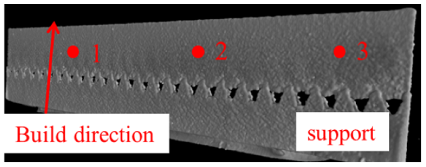
2.1. Material and Specimen Preparation

Commercially available gas-atomized 316L stainless steel powder with a powder particle size distribution of 15–45 µm and spherical morphology was used in this work. The chemical composition of the manufactured specimens was analyzed with optical emission spectrometry and is displayed in Table 1.
In the SLM process, 3D metal objects can be produced directly from powder material using a laser beam. The objects are built up layer by layer in the z-direction. The whole process is carried out using the “SLM 280 2.0” machine in an inert gas atmosphere. The laser power was set to 192 W with a laser speed of 580 mm/s in the process. Rectangular specimens with dimensions of 50 × 5 × 0.4 mm were manufactured for the investigations. The manufactured specimen can be seen in Figure 1 as a CT-image. The support structure of the sample was mechanically removed, which can be seen in Figure 1 from the bottom in the build direction.
For a subsequent microstructural characterization, the manufactured specimens were prepared metallographically. For this, specimens were cut and mounted in electrically conductive phenolic resin in order to investigate two different planes (one perpendicular and one parallel to their building direction during SLM). The mounted specimens were ground with silicon carbide abrasive paper to a grit of 2400, then mechanically polished with a diamond suspension of 1 µm, followed by etching with V2A etchant at room temperature for 30 to 60 s.

2.2. Microstructural Characterization

A phase analysis was performed using X-ray diffraction (XRD) with a Bruker D8 Discovery diffractometer with monochromatic Cu Kα radiation. The measurements were performed on metallographically prepared specimens (plane parallel to the build-up direction) at a voltage of 40 kV with 2θ scans ranging from 30° to 90° in steps of 0.04°/s. For microstructure examinations, an optical microscope Zeiss, Imager.A2m, (Carl Zeiss in Oberkochen, Germany) was used. A more detailed examination of the microstructure and elemental distribution was performed using a transmission electron microscope (TEM) operated in scanning transmission electron microscopy (STEM) mode and equipped with an energy-dispersive X-ray spectroscopy (EDS) detector. Microscopic images were obtained using high-angle annular dark field (HAADF) imaging. TEM lamella for TEM/STEM and corresponding EDS analysis were obtained using focused ion beam (FIB) processing. Atomic resolution HR-TEM analyses were performed on the TEM lamella to determine the phase domains and crystal orientation at the interface between cellular structures.
For SEM imaging and TEM lamella preparation, a Scios 2 HiVac FIB/SEM instrument (Thermo Fisher in Waltham, MA, USA) equipped with an EDAX Octane Elite EDS/EDX system was used. For TEM/STEM imaging and EDS analysis, a Talos 200X instrument (Thermo Fisher in Waltham, MA, USA) was used.

3. Results

The XRD patterns taken from an additively manufactured 316L specimen (Figure 1) are shown in Figure 2 and indicate that austenite is formed during the SLM process. While typical reflexes could be found for the {111}, {200} and {220} planes of the austenite phase, no hints for δ-ferrite are present. Figure 3 shows micrographs of the plane perpendicular to the building direction of the specimen taken with optical microscopy. On the left side, the contour and overlapping of several solidified melt pools are clearly visible. Furthermore, the melt pool boundaries appear as fine, dark lines as a contrast to the structures within the melt pools. Another characteristic is the observable grains, which were made visible by etching. It is noticeable that some grains have a length greater than 100 µm and that others tend to grow beyond the melt pool boundaries. On the right side, two melt pool boundaries and several grains are shown with higher magnification. What can be seen is that within the grains, very fine sub-grain structures exist. These structures appear as colonies of roundly or elongated, distorted cells with different sizes. Scanning electron microscope (SEM) micrographs of the plane perpendicular to the building direction are illustrated in Figure 4. The fine sub-grain characteristics, such as sub-grain boundaries and a complex cellular microstructure, are shown in Figure 4a. The different roundly and elongated, distorted cellular structures are now much more clearly visible, whereas the elongated structures show a parallel growth direction. For a more detailed microstructural examination, a section of a sub-grain boundary was investigated using STEM (Figure 5). Additionally, to analyze the chemical composition, EDS was performed for three different areas within the investigated section. Figure 5 shows the areas (outlined in different colors) where EDS analysis was performed separately. The results in Table 2 show that in comparison to the adjacent matrix, the boundary is somewhat depleted in iron (Fe), but enriched in silicon (Si), chromium (Cr), manganese (Mn) and molybdenum (Mo).
Furthermore, HR-TEM analyses with atomic resolution were performed to determine phase domains at the sub-grain-boundary at the enriched and non-enriched regions (Figure 6), which are already mentioned in Figure 5. At the enriched area, ferrite can be observed (Figure 6a) and at the non-enriched area the austenite is dominating (Figure 6b).

4. Discussion

4.1. Microstructural Evolution

The microstructural evolution of stainless steels is a highly complex process that depends on the chemical composition of the alloy as well as on the cooling conditions. Depending on the alloying element, it can either act as a ferrite or as an austenite stabilizer. By categorizing and comparing the individual elements with their amounts, it is possible to predict the resulting microstructure. Important and helpful tools are constitutional diagrams such as the Schaeffler diagram and the WRC 1922 diagram, as they can help to predict the resulting amount of austenite and ferrite phases in the microstructure based on the chemical composition and the ferrite and austenite stabilizers of an alloy, respectively [14,15]. As the Schaeffler diagram only shows the resulting microstructure at room temperature and does not take into account the solidification paths, these are integrated in the WRC 1992 diagram and allow a more accurate representation of the real situation. The enrichment of the alloying elements like Si, Cr and Mo in the sub-grain boundaries of the SLM-manufactured 316L can lead to the formation of ferrite in addition to austenite. Furthermore, according to the WRC 1992 diagram, the occurring solidification of the metallic melt can either be an FA type (ferrite solidifies first, then austenite) or an AF type (austenite solidifies first, then ferrite). Thus, if the solidification pathway for SLM 316L is an FA type, again some amount of ferrite in the resulting microstructure could be expected. However, the XRD patterns in Figure 2 reveal only peaks corresponding to the austenite phase; no clear hints of a ferrite phase could be detected. The amount of ferrite could be below 5%. This would be under the determination limit using the XRD-method. However, on the basis of the atomic resolution HR-TEM results, it can be concluded that at the enriched area, ferrite is also present, and at the non-enriched area austenite is dominating (Figure 6). This can be attributed to the high cooling rates during the solidification of the metallic melt. Theoretically, and according to the constitution diagrams, both phases could form during cooling. According to Lippold and Kotecki [16], the kinetics are higher for the austenite phase and as a result, the microstructure of SLM 316L is supposed to consist of austenite, and the formation of ferrite is suppressed. Nevertheless, Kurzynowski et al. [9] investigated the influence of different laser powers on the microstructural evolution of SLM 316L and were actually able to find some δ-ferrite using XRD, when they used a laser power of 100 W. In contrast, when they used a higher laser power of 200 W, they could not find any δ-ferrite, assuming its amount was below XRD detection threshold. This corresponds well with other studies [13,17,18], where the SLM 316L specimen was manufactured with laser energy densities of 80–150 J/mm3, and δ-ferrite could only be found in specimens manufactured with lower energy densities, indicating that the amount of δ-ferrite is smaller the higher the energy density is. Thus, the presence of delta-ferrite is a possibility, although its amount may be below the XRD detection threshold. Nonetheless, it existence could affect the resulting mechanical and electrochemical properties, as it leads to a slight increase in the yield strength and change in the (local) corrosion resistance due to the formation of micro-galvanic cells [9].

4.2. Solidification Structures

The solidification structure of a metallic melt can have different types, like planar, cellular or dendritic. Which type of solidification occurs strongly depends on the stability of the solidification front, which is influenced by cooling rates and solidification conditions [19]. As the heat during the layer-building process is primarily extracted by the underlying consolidated layers during SLM, a preferably unidirectional heat flow takes place. While this tends to have a stabilizing effect on the solidification fronts of pure metals, its influence is more complex for alloys. This is attributed to the effect of constitutional undercooling, which may happen due to the redistribution of soluted alloying elements and can lead to an undercooled melt. The degree of constitutional undercooling has a direct influence on the stability of the solidification front, and therefore on the solidification type. It can be mathematically described as indicated by Equation (1), where G represent the real temperature gradient at the solidification front, R the solidification rate, mL the slope of the liquidus line, which is dependent on the phase diagram of the current composition, c0 the initial concentration of the melt, k the segregation coefficient, DL the diffusion coefficient in the melt and T0 the temperature difference between the solidus and liquids temperature at c0. Now, if the right term of the equation is greater the left term, the solidification front is destabilized and the solidification type follows a cellular or dendritic solidification, as a planar solidification is no longer possible [20,21].
G R < m L c 0 ( 1 k ) k D L = T 0 D L
This process is linked to the partition coefficients of the alloying elements, as values of k that are further away from the ideal value of 1 lead to a higher extent of solute partitioning, thereby favoring other solidification types than planar solidification. Furthermore, the occurring cooling rates during the SLM process of stainless steels can be estimated by using the width of the solidification structures, according to [22]. As a width of 0.5 µm can be determined with the TEM micrographs, a cooling rate of approximately 106 K/s can be assumed. Table 3 shows the equilibrium distribution coefficient k0 during solidification in austenite. The further this value differs from 1, the higher the enrichment of the elements in the melt can be expected. This is for ferrite stabilizing elements higher than those for austenite. As all alloying elements of 316L have a k0 value unequal to 1 and very high cooling rates occur during the SLM process, the right term of Equation (1) is higher than the left term. Thus, constitutional undercooling and a primary cellular solidification type is ought to happen for SLM 316L, as can be seen in Figure 3 and Figure 4. Additionally, the effects are clearly visible in Figure 5 in the form of micro-segregation and solute enrichment, as higher amounts of the alloying elements (except Ni) were found within the structure boundary resulting in ferrite. Furthermore, constitutional undercooling and a primary cellular solidification type ought to happen for SLM 316L, as can be seen in Figure 3 and Figure 4. Additionally, the effects are clearly visible in Figure 5 in the form of micro-segregation and solute enrichment, as higher amounts of the alloying elements (except Ni) were found within the structure boundary, resulting in ferrite formation. Figure 4b shows illustrated cellular structures that have grown in different directions. This is the result of grains growing from multiple locations into the center of a melt pool as they follow the maximum temperature gradient, which is located perpendicular to the melt pool boundary. Because the growth of the grains starts from the melt pool boundary and the melt pool has a concave shape, the angle under which the grain growth into the melt pool changes depending on the location within the melt pool boundary [23,24]. A similar solidification behavior during the SLM process has been described for other steels, e.g., 17-4 PH steel in the study of Rafi et al. [24]. Additionally, partial elemental enrichment of specific boundary structures within the microstructure of SLM 316L could also be verified by scanning kelvin probe force microscopy (SKPFM). Kong et al. reported [25] a higher Volta potential of approximately 5 mV for sub-grain boundaries in comparison to the inner sub-grains, due to the higher amount of Cr and Mo within the boundaries. Eventually, as described before, several randomly distributed fine precipitations or inclusions with sizes in the range of 50–200 nm were detected within the microstructure of SLM 316L. In this area, ferrite could be determined in addition to the austenite using HR-TEM analysis. Other authors identified them either as amorphous silicate containing Mn and Cr [17,18] or Si, Mn and Cr oxides [26,27].

5. Conclusions

In this work, the microstructural evolution and characteristics of SLM-manufactured 316L stainless steel was investigated. The main conclusion can be drawn as follows:
(1)
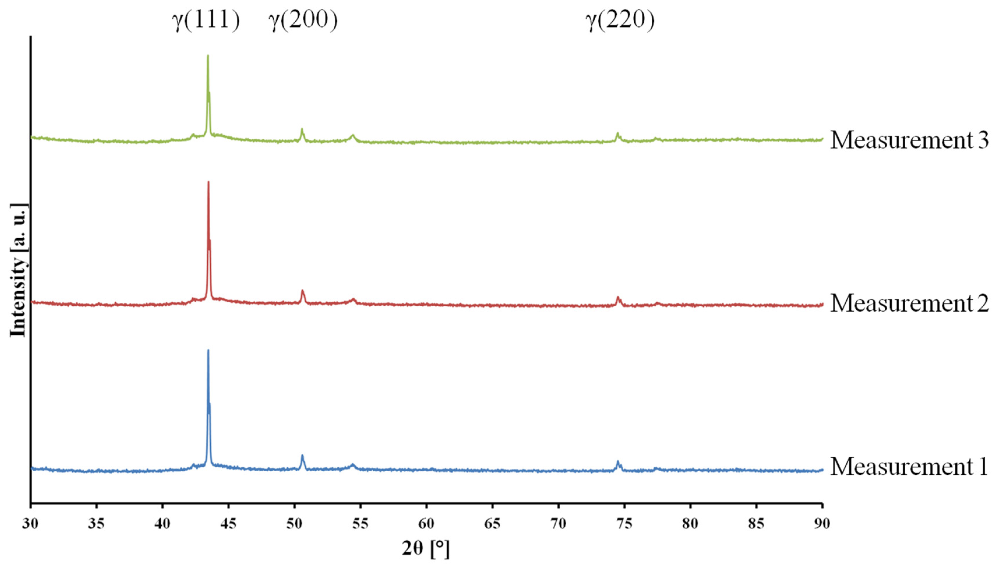
According to the XRD analysis, the prevailing phase in the microstructure is austenite;
(2)
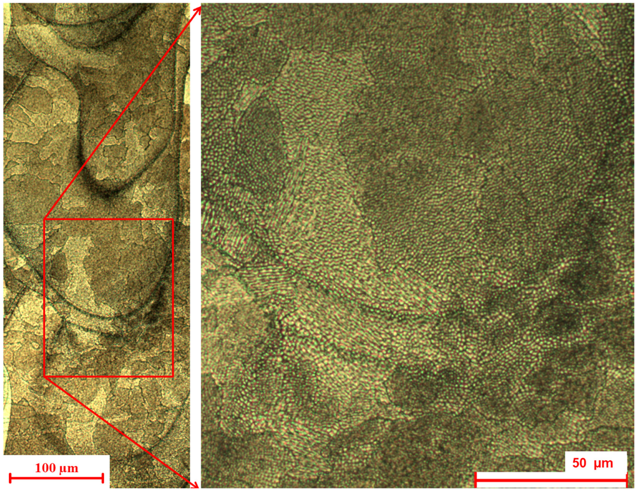
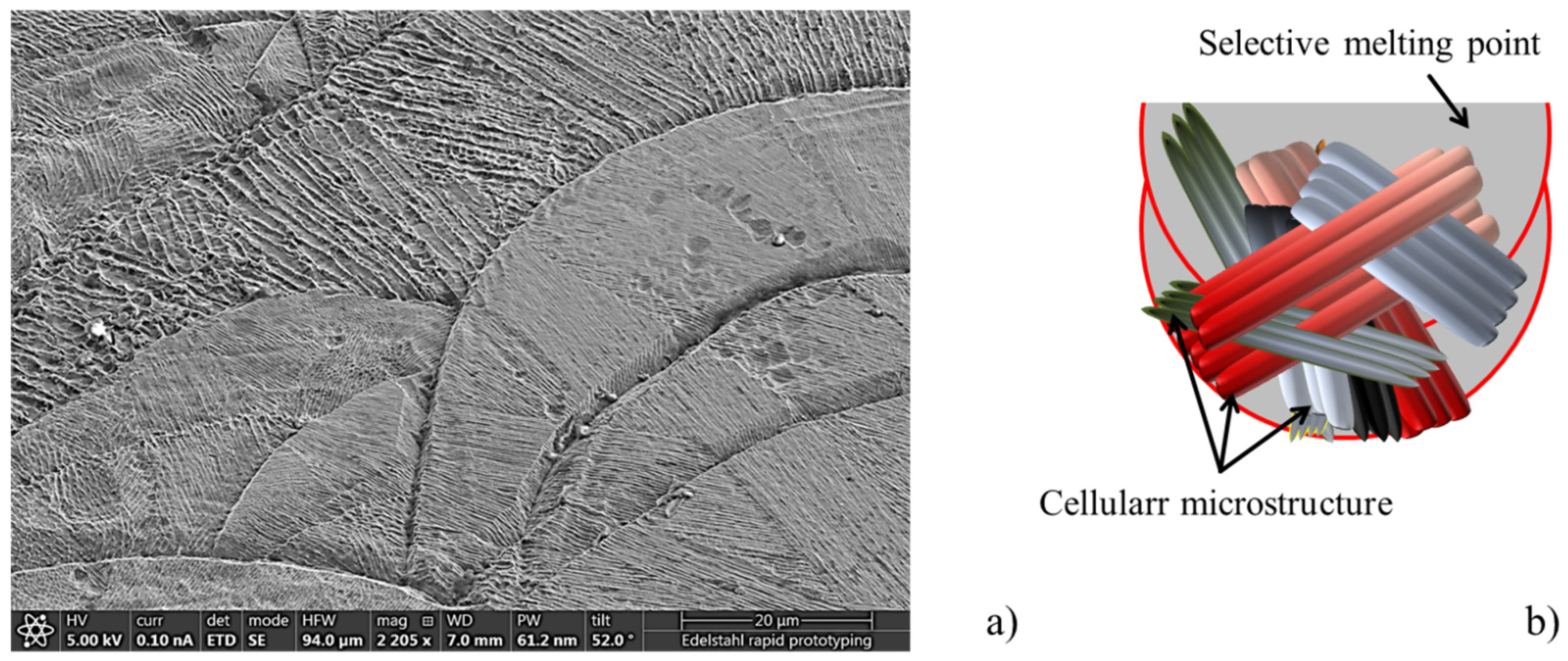
The high cooling rates and constitutional undercooling lead to the formation of very fine grains, sub-grain structures and cellular structures;
(3)
Colonies of cellular structures with different orientations form due to the complex heat flow within the melt pools;
(4)
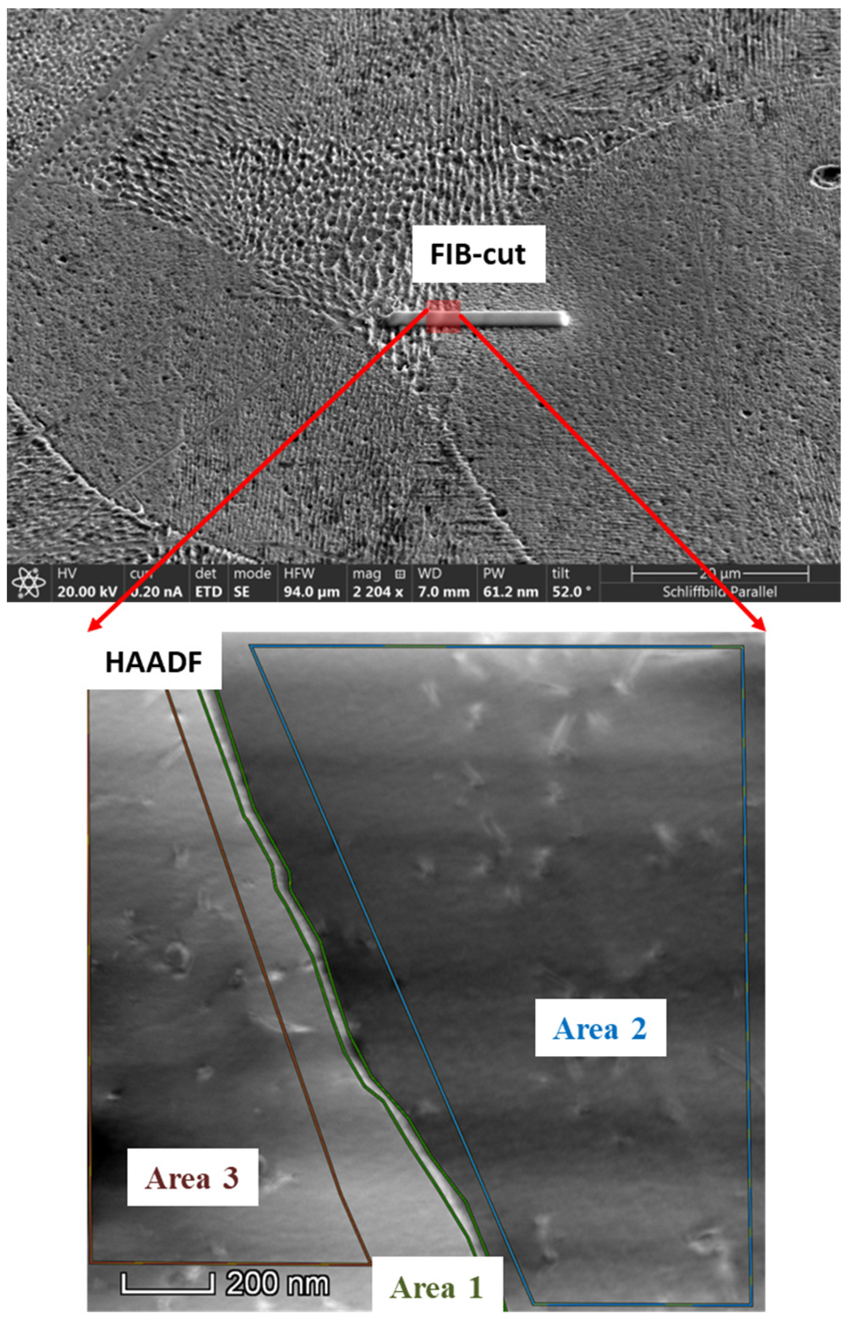
Micro-segregation occurs and results in an enrichment of the sub-grain boundaries with most of the alloying elements;
(5)
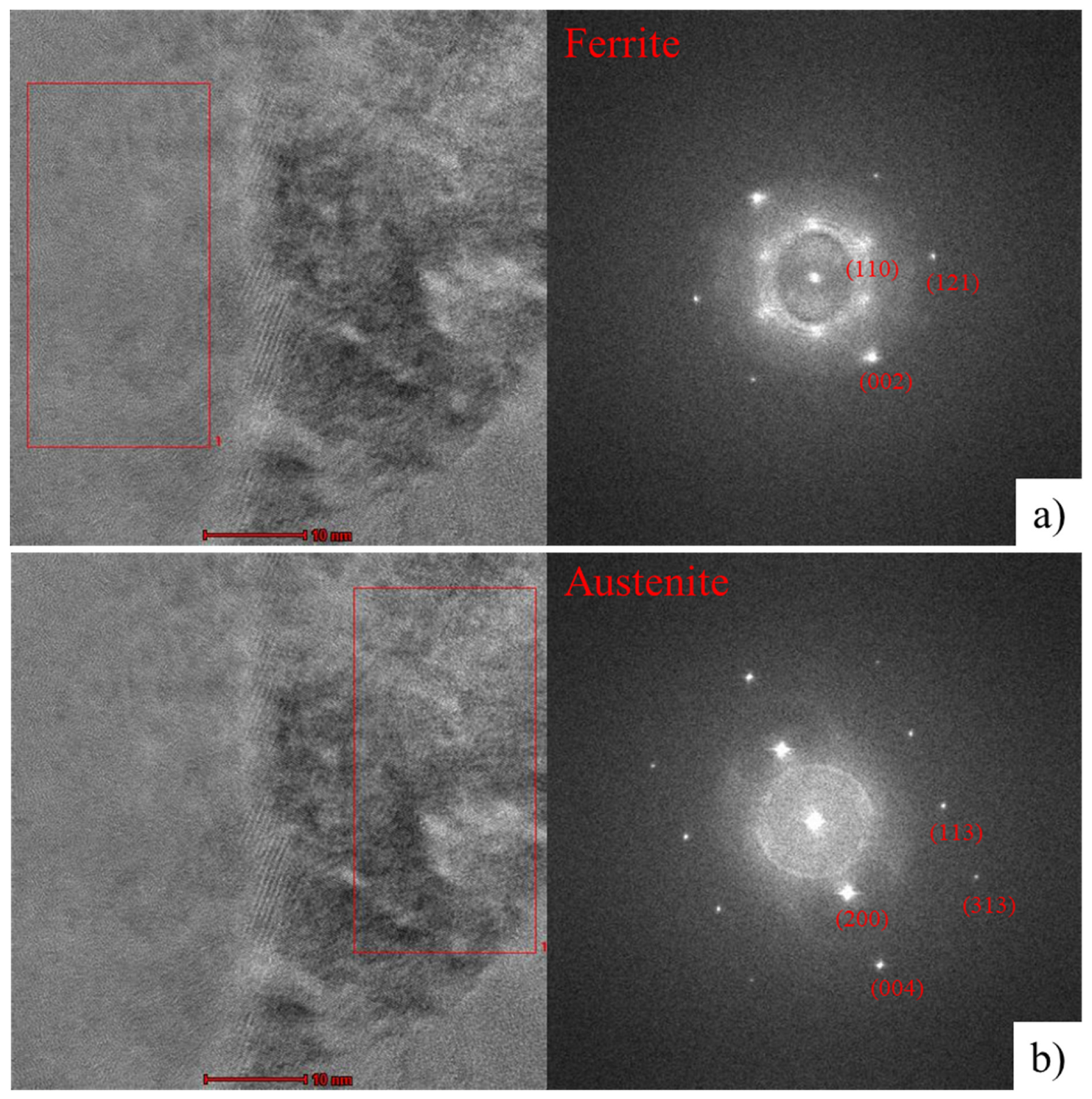
Using the atomic resolution HR-TEM analysis, ferrite could be determined in the enriched area of the sub-grain boundaries.
It was found that the high cooling solidification conditions in the SLM process for 316L leads to the formation of austenite and partially to ferrite, which is normally not existent in conventionally manufactured 316L products. This happens through constitutional supercooling, whereby during solidification the melt is enriched with ferrite stabilizing elements. The difference in chemical composition at the substructures could be determined by using EDS. The existence of ferrite can be found by using TEM analysis. Methods such as XRD are not sufficient as ferrite is below the detection limit of this method.
The microstructure significantly affects the resulting properties of the metallic components. Therefore, the aim of further investigations will be to analyze the mechanical and electrochemical properties of 316L stainless steel manufactured using SLM, as well as the influence of heat treatment processes.

Author Contributions

Conceptualization, E.F.Ö., D.P., H.M.-J. and C.M.; methodology, E.F.Ö., D.P. and H.M.-J.; validation, E.F.Ö., D.P., H.M.-J. and C.M.; formal analysis, E.F.Ö., D.P., H.M.-J. and C.M.; investigation, E.F.Ö., Y.T. and R.T.; data curation, E.F.Ö., Y.T. and R.T.; writing—original draft preparation, E.F.Ö., D.P., H.M.-J. and C.M.; writing—review and editing, E.F.Ö., D.P., H.M.-J. and C.M.; supervision, E.F.Ö., H.M.-J. and C.M.; project administration, E.F.Ö., H.M.-J. and C.M.; funding acquisition, H.M.-J. All authors have read and agreed to the published version of the manuscript.

Funding

The research received no external funding. The APC was funded by the Institute of Materials Science and Engineering Tuttlingen-IWAT, Hochschule Furtwangen Campus Tuttlingen and University of Freiburg.

Data Availability Statement

The data presented in this study are available on request from the corresponding author. The data are not publicly available due to privacy reasons.

Acknowledgments

Cooperative doctorate: Generation mechanisms for microstructures “GenMik”, University of Freiburg.

Conflicts of Interest

The authors declare no conflict of interest. The funders had no role in the design of the study; in the collection, analyses, or interpretation of data; in the writing of the manuscript; or in the decision to publish the results.

References

  1. Herzog, D.; Seyda, V.; Wycisk, E.; Emmelmann, C. Additive manufacturing of metals. Acta Mater. 2016, 117, 371–392. [Google Scholar] [CrossRef]
  2. Frazier, W.E. Metal Additive Manufacturing: A Review. J. Mater. Eng. Perform. 2014, 23, 1917–1928. [Google Scholar] [CrossRef]
  3. DebRoy, T.; Wei, H.L.; Zuback, J.S.; Mukherjee, T.; Elmer, J.W.; Milewski, J.O.; Beese, A.M.; Wilson-Heid, A.; De, A.; Zhang, W. Additive manufacturing of metallic components—Process, structure and properties. Prog. Mater. Sci. 2018, 92, 112–224. [Google Scholar] [CrossRef]
  4. Berman, B. 3-D printing: The new industrial revolution. Bus. Horiz. 2012, 55, 155–162. [Google Scholar] [CrossRef]
  5. Kruth, J.-P.; Dadbakhsh, S.; Vrancken, B.; Kempen, K.; Vleugels, J.; van Humbeeck, J. Additive Manufacturing of Metals via Selective Laser Melting: Process Aspects and Material Developments. In Additive Manufacturing: Innovations, Advances, and Applications; Srivatsan, T.S., Sudarshan, T.S., Eds.; CRC Press: Boca Raton, FL, USA, 2016. [Google Scholar]
  6. Kruth, J.-P.; Levy, G.; Klocke, F.; Childs, T. Consolidation phenomena in laser and powder-bed based layered manufacturing. CIRP Ann.—Manuf. Technol. 2007, 56, 730–759. [Google Scholar] [CrossRef]
  7. Song, B.; Zhao, X.; Li, S.; Han, C.; Wei, Q.; Wen, S.; Liu, J.; Shi, Y. Differences in microstructure and properties between selective laser melting and traditional manufacturing for fabrication of metal parts: A review. Front. Mech. Eng. 2015, 10, 111–125. [Google Scholar] [CrossRef]
  8. Sumita, M.; Hanawa, T.; Teoh, S.H. Development of nitrogen-containing nickel-free austenitic stainless steels for metallic biomaterials—Review. Mater. Sci. Eng. C 2004, 24, 753–760. [Google Scholar] [CrossRef]
  9. Kurzynowski, T.; Gruber, K.; Stopyra, W.; Kuźnicka, B.; Chlebus, E. Correlation between process parameters, microstructure and properties of 316 L stainless steel processed by selective laser melting. Mater. Sci. Eng. A 2018, 718, 64–73. [Google Scholar] [CrossRef]
  10. Sedriks, A.J. Corrosion of Stainless Steels. In Encyclopedia of Materials: Science and Technology; Elsevier: Amsterdam, The Netherlands, 2001; pp. 1707–1708. [Google Scholar]
  11. Bernstein, I.M. Handbook of Stainless Steels; McGraw-Hill: New York, NY, USA; Düsseldorf, Germany, 1977. [Google Scholar]
  12. Davis, J.R. (Ed.) Stainless Steels, 1st ed.; ASM International: Materials Park, OH, USA, 1994. [Google Scholar]
  13. Zhong, Y.; Liu, L.; Wikman, S.; Cui, D.; Shen, Z. Intragranular cellular segregation network structure strengthening 316L stainless steel prepared by selective laser melting. J. Nucl. Mater. 2016, 470, 170–178. [Google Scholar] [CrossRef]
  14. Schaeffler, A. Constitution Diagramm for Stainless Steel Weld Metal. Met. Prog. 1949, 56, 680. [Google Scholar]
  15. Kotecki, D.J.; Siewert, T.A. WRC-1992 Constitution Diagram for Stainless Steel Weld Metals: A Modification of the WRC-1988 Diagram: Refined constitution diagram offers more accurate FN prediction for Cu-containing stainless steel and dissimilar joints. Weld. Res. Suppl. 1992, 71, 171–178. [Google Scholar]
  16. Lippold, J.C.; Kotecki, D.J. Welding Metallurgy and Weldability of Stainless Steels; Wiley-Interscience: Hoboken, NJ, USA, 2005. [Google Scholar]
  17. Sun, Z.; Tan, X.; Tor, S.B.; Yeong, W.Y. Selective laser melting of stainless steel 316L with low porosity and high build rates. Mater. Des. 2016, 104, 197–204. [Google Scholar] [CrossRef]
  18. Saeidi, K.; Gao, X.; Zhong, Y.; Shen, Z.J. Hardened austenite steel with columnar sub-grain structure formed by laser melting. Mater. Sci. Eng. A 2015, 625, 221–229. [Google Scholar] [CrossRef]
  19. Kou, S. Welding Metallurgy, 2nd ed.; Wiley: Hoboken, NJ, USA, 2003. [Google Scholar]
  20. Stefanescu, D.; Ruxanda, R. Fundamentals of Solidification; ASM International: Materials Park, OH, USA, 2004. [Google Scholar]
  21. Brooks, J.A.; Baskes, M.I. Microsegregation modeling and transformation in rapidly solidified austenitic stainless steels welds; ASM International: Materials Park, OH, USA. Recent Trends Weld. Sci. Technol. 1990, 153–158. [Google Scholar]
  22. Elmer, J.W.; Allen, S.M.; Eagar, T.W. The influence of cooling rate on the ferrite content of stainless steel alloys. Recent Trends Weld. Sci. Technol. 1990, 165–170. [Google Scholar]
  23. Vrancken, B.; Thijs, L.; Kruth, J.-P.; van Humbeeck, J. Microstructure and mechanical properties of a novel β titanium metallic composite by selective laser melting. Acta Mater. 2014, 68, 150–158. [Google Scholar] [CrossRef]
  24. Rafi, H.K.; Pal, D.; Patil, N.; Starr, T.L.; Stucker, B.E. Microstructure and Mechanical Behavior of 17-4 Precipitation Hardenable Steel Processed by Selective Laser Melting. J. Mater. Eng. Perform. 2014, 23, 4421–4428. [Google Scholar] [CrossRef]
  25. Kong, D.; Dong, C.; Ni, X.; Zhang, L.; Luo, H.; Li, R.; Wang, L.; Man, C.; Li, X. The passivity of selective laser melted 316L stainless steel. Appl. Surf. Sci. 2020, 504, 144495. [Google Scholar] [CrossRef]
  26. De Bellefon, G.M.; Bertsch, K.M.; Chancey, M.R.; Wang, Y.Q.; Thoma, D.J. Influence of solidification structures on radiation-induced swelling in an additively-manufactured austenitic stainless steel. J. Nucl. Mater. 2019, 523, 291–298. [Google Scholar] [CrossRef]
  27. Wang, Y.M.; Voisin, T.; McKeown, J.T.; Ye, J.; Calta, N.P.; Li, Z.; Zeng, Z.; Zhang, Y.; Chen, W.; Roehling, T.T.; et al. Additively manufactured hierarchical stainless steels with high strength and ductility. Nat. Mater. 2018, 17, 63–71. [Google Scholar] [CrossRef] [PubMed]
  28. RWTH Aachen. Werkstoffkunde Stahl für Studium und Praxis, 3rd ed.; Aachen: Mainz, Germany, 2010. [Google Scholar]
Figure 1. Computed tomography image of the SLM flat specimen. The build direction shows how the specimen was built layer to layer on the process table. The red points are the measurement areas for the XRD analysis in Figure 2.
Jeta 01 00005 g001
Figure 2. XRD diffraction patterns for SLM 316L specimens (parallel to the build direction). JCPDS 6-0696 for ferrite and JCPDS 4-0829 for austenite were used for the evaluation of the spectra.
Jeta 01 00005 g002
Figure 3. Microstructure of SLM 316L perpendicular to the build direction, visualized using optical micrography.
Jeta 01 00005 g003
Figure 4. Microstructure analysis of SLM 316L by SEM showing (a) the cellular structure, and (b) a schematic drawing showing how various grains grow into the melt pool center with different angles.
Jeta 01 00005 g004
Figure 5. STEM image of a sub-grain boundary (outlined in green) and determination of the chemical composition (Table 2) in different areas using EDS analysis: Area 1 is the interface/grain boundary, in the green outlined area; Area 2 is the blue outlined area; and Area 3 is the red outlined area.
Jeta 01 00005 g005
Figure 6. HR-TEM analysis with atomic resolution and their corresponding FFT patterns at the sub-grain boundary, as shown in Figure 5, reveals (a) the ferrite phase (with corresponding lattice planes) in the alloy-enriched region; (b) the presence of austenite (with corresponding lattice planes) in the unenriched region.
Jeta 01 00005 g006
Table 1. Chemical composition of the SLM 316L specimen (in wt.-%).
316LC %Si %Mn %P %S %Cr %Mo %Ni %Fe %
Specimen0.030.670.920.020.0016.102.3511.00Balanced
DIN EN 10088-3Max
0.03
Max
1.00
Max
2.00
Max
0.05
Max
0.03
16.50–18.502.00–2.5010.00–13.00Balanced
Table 2. Chemical compositions through EDS analysis calculated from the respective spectra accumulated within the respective areas. The colors correspond to those shown in the lower part of Figure 5.
ElementsArea 1 [%]Area 2 [%]Area 3 [%]
Si1.13 ± 0.10 0.72 ± 0.100.88 ± 0.10
Cr17.61 ± 0.3516.49 ± 0.3516.81 ± 0.35
Mn1.09 ± 0.180.86 ± 0.180.66 ± 0.18
Fe66.14 ± 0.2068.48 ± 0.2067.97 ± 0.20
Ni11.72 ± 0.1011.59 ± 0.1011.75 ± 0.10
Mo2.31 ± 0.081.85 ± 0.081.94 ± 0.08
Table 3. Equilibrium distribution coefficient (k0) of the alloying elements of 316L stainless steel during solidification in austenite [28].
Elementsk0 (γ/L)
Fe1
Cr0.83
Ni0.90
Si0.52
Mn0.78
Mo0.63
Disclaimer/Publisher’s Note: The statements, opinions and data contained in all publications are solely those of the individual author(s) and contributor(s) and not of MDPI and/or the editor(s). MDPI and/or the editor(s) disclaim responsibility for any injury to people or property resulting from any ideas, methods, instructions or products referred to in the content.

