1. Introduction
With the recent advancement in computing technology, real-time embedded software development has been widely spread in various fields, such as aviation, aerospace, medical, transportation, and manufacturing [
1,
2]. Most real-time embedded software is highly tied to a specific hardware (e.g., microcontroller board) with a limited purpose like controlling a particular type of physical equipment. As a result, many practices may remain in a manual design process [
3,
4].
One way to improve the process is to model an embedded software design using the formal method. A critical technique in the formal model is the finite state machine, which employs the concept of “state” to describe an overall system’s status after an event or operation. In this way, an embedded system design is modeled as a combination of several intertwined event-and-state sequences. This rigorous state machine presentation elevates design thinking to avoid manual design processes or ad hoc implementations and further aids later testing to increase the quality [
4,
5].
While using the state machine to model an embedded system design seems to be a good solution, increasing requests for more functionalities or attaching more sensors for detecting the system’s internal parts or surrounding environmental changes, reactions of external parties or behaviors of its internal component add complexity to the embedded software. These increasing additional complexities bring new challenges to simply applying the state machine to a modern embedded system design.
At the same time, educators face the same challenge in cooperating with modern embedded system design. The characteristic of blurring the boundary between hardware and software in embedded system design leads to tangling the design logic between low-level control and application flow [
6]. When a software engineering course project starts the embedded software design by treating a system as a whole, the implicit states of internal components and tangling between hardware and software at the lower level makes students wander in modeling system states in the design. Thus, a designer’s thinking must be guided throughout the process to conduct embedded software design effectively and efficiently.
On the other hand, the existing design methods and thinking in software engineering prompt the exploration of a novel approach for designing embedded systems. Current software design methods, such as Object-Oriented Analysis Design (OOAD) [
7,
8], the Structured Analysis and Design Technique (SADT) [
9,
10,
11,
12], and data flow analysis, or approaches like one-dimensional decomposition are insufficient to deal with embedded software design. One main reason for this mentioned in the past research [
13] was that top-down designs could not work for control flow. Along with the same reason, we further argue that it is not easy for one-dimensional decomposition to separate the inevitable intertwining of requirements and resulting structures during the early design stage [
8]. It is also hard for a designer to associate requirements or specifications with classes and objects in an embedded system design, particularly in a real-time system [
14]. In addition, principles in design thinking have evolved from exploring problem and solution spaces to the combination of divergent and convergent thinking, building prototypes, testing early, etc. [
15,
16,
17]. Recent studies about integrating design thinking with software development emphasize using design thinking to support requirement engineering activities and to align with the agile process [
18,
19]. Although phases (e.g., empathize, define, ideate, prototype, and test) or techniques (e.g., warm-up, unpacking, idea generation, etc.) in design thinking are applied to aid software design [
19,
20,
21,
22,
23], few studies work on human reasoning on decision making in embedded system design. These deficiencies of existing methods reveal a need for a new software design approach to develop embedded software.
Two methods, the Synthesis-Based Software Design Framework (SSDF) [
24] and Process and Artifact State Transition Abstraction (PASTA) [
25], which have different focuses, help the engineer to design software. Instead of using one-dimensional top-down decomposition to lay out the system from abstract to concrete details in one hierarchy, the SSDF introduces an addition hierarchy that separates what the designer wants to fulfill and how the system behaves. PASTA, used in the family-based software product line, is a way to model complex processes with states. In PASTA, the designer specifies a design artifact hierarchy and state changes of individual artifacts to describe the process. Therefore, we proposed a design approach, the Synthesis-Based Stateful Software Design Approach (SSSDA), which extracts the main ideas from the SSDF and PASTA to remedy the drawback of the current state machine and single decomposition approaches in the embedded system design.
Our main contribution is that the SSSDA provides a systematic way to guide an engineer’s reasoning, particularly helping inexperienced engineers to determine modules, in embedded software design. To demonstrate the SSSDA, a real-world embedded software design is illustrated. In the project, the team built an attachment to an existing bandsaw, consisting of mechanical and electronic components, to give an automatic cutting mechanism. The presented case study showed that our SSSDA could turn the complicated finite state machine and highly flexible modular decomposition into systematic and comprehensive procedures, enabling the efficient utilization of students.
2. Related Research
Our study involves four major areas: software design method, design thinking in software development, embedded system design, and embedded system education. Related work in each area will be discussed in the following sections.
2.1. Design Theory and Methodology in Software Engineering
According to the characteristics of the approach, past software design methods can be classified into five kinds. They are level, structured, data structure, object-oriented, and component-based approaches.
In 1971, Niklaus Wirth [
26] addressed the top-down (usually termed stepwise refinement) approach that considers a program with various levels. The process starts at the top (system) level and breaks down the system into smaller functional modules. However, since the method is algorithm-like and relatively close to the programming level, the complicated interoperations between modules and the complexity due to more functions make extending the method to large-scale software systems inappropriate and uneconomical.
The Structured Analysis and Design Technique (SADT) [
9,
10,
11,
12], a critical approach in a family of structured methods, primarily uses two primary requirement analysis techniques that capture the system requirements, namely data flow analysis and activity analysis. Data flow analysis produces an artifact, a data flow diagram (DFD), which shows the data flow between the system’s functions. Activity analysis uses activity diagrams to represent relations between inputs, controls, and activities. However, DFD may be helpful in detailed design. If a developer considers design at the system level, it is not easy to merely start from DFD.
Jackson Structured Programming (JSP) and Jackson System Development (JSD) methods that were both invented by Jackson in the 1980s are data-structure-oriented approaches [
27,
28]. JSP primarily focuses on coding and program analysis skills. JSD supports all the system development steps during the software life cycle and consists of three major phases—modeling, network, and implementation. JSD and JSP are difficult to understand due to pseudo-code representation and cannot fit well in high-level abstraction. Therefore, these two methods cannot be applied to capture hardware and software abstractions in embedded systems.
The object-oriented design (OOD) method is currently widely used. Russ Abbott originated it, and many design methods, such as Grady Booch’s approach, have been proposed since the late 1980s [
7,
8]. The idea behind OOD was to create software systems by modeling them in terms of real-world “objects” and the operations performed on these objects. To date, many derived approaches from OOD have been suggested.
Shlaer and Mellor [
29] suggested objects’ behaviors should be modeled by conventional state-transition diagrams, which laid the basis of a genuine OO even though some argued that they are still data-driven. Unlike those data-driven OO approaches, Wirfs-Brock and her colleagues [
30] developed the responsibility-driven design (RDD) technique. The most important contribution of RDD was the idea of using CRC cards and stereotypes for designs. CRC showed the responsibilities of the class and its collaborations with other objects as a starting point of the design. Using such a technique can help the designer identify objects in the beginning of the software design.
Rather than directly carrying out OO analysis, in 1992, Jacobson et al. [
8] suggested the Objectory (Object Factory) method that uses the use case to begin the analysis. The classes in the software were then derived from the use cases. The use case technique marked a significant step forward in Object-Oriented Software Engineering (OOSE).
The state-of-the-art OO approach can be thought to be the Unified Process (UP), developed primarily by Grady Booch, James Rumbaugh, and Ivar Jacobson [
8]. Remarkably, the Unified Process is much influenced by the concept of the Objectory method. The UP considers various elements associated with OO modeling to be supported by a universal graphical notation—the Unified Modeling Language (UML). The UML became very popular in many engineering fields. The UP is also extended to various commercial forms, and the most famous one is the Rational Unified Process (RUP).
Component-based design (CBD) arose due to emerging large-scale and complex applications. It mimics the physical system design, where components have well-defined roles and interfaces; in this way, software components can be reusable. CBD is also considered a higher level of abstraction than objects. The interfaces of a component are typically defined by using an interface definition language (IDL). Pohthong and Budgen [
31,
32] suggested two strategies, element first and framework first. Element first begins with identifying the general needs of the design problem. Then, engineers search for components that satisfy functionality and finally compose them to form a system. Framework first decomposes the design problem into fairly well-defined sub-problems and then finds a set of components that fit individual sub-problems.
2.2. Design Thinking in Software Development
Design thinking, consisting of a set of iterative working spaces (also known as phases), is viewed as a process (also known as a model) [
16]. In each working space, a set of techniques can be applied [
33]. Past research reported many design thinking models and techniques of working spaces. In software engineering, some design thinking models were mapped to the agile process [
19], and design thinking techniques were used to support the understanding of the problem to be solved and to validate solutions for meeting customers’ needs [
20,
34,
35].
Higuchi et al. [
36] applied the model that contains inspiration, ideation, and implementation phases to the Scrum framework for developing a digital game project. Lucena et al. [
37] combined the model that contains empathy, define, ideate, prototype, and test phases with Scrum to create their IBM Design Thinking Software Development Framework and applied their proposed framework to five real-world software development projects. Dobrigkeit et al. [
21] accompanied design thinking techniques with Scrum events. For example, unpacking and knowledge sharing techniques were used in the Daily Scrum. Testing and feedback techniques were used in the Sprint Review. In their study, these techniques were considered a worthwhile addition to Scrum events. Levy et al. [
23] investigated the impact of a design thinking workshop on the requirement elicitation of an organization’s business process. Their findings showed that applying design thinking led to new requirements regarding the business process from both human and technical perspectives. In embedded system development, Araújo et al. [
38] identified the benefits and trends of the adoption of design thinking. They also investigated how empathy, define, ideate, prototype, and test phases can be applied in the development.
2.3. Embedded System Design
Formal methods like Finite State Machine (FSM) are widely used for describing software behaviors. Conventional design methods often constructed their state machines as sequential control programs in programmable logic controllers, which resulted in hardwiring the logic of the state machine in the code. Therefore, many research tasks emphasized reconfigurability and reusability for components or state machines in an embedded system. Wang and Shin [
4] proposed an architecture to support the integration of reusable components. In their proposed platform, the behavior of each component is specified as an FSM, and the integrated behavior is modeled as a nested FSM. Wagner et al. [
13] built a commercial tool, StateWORKS, which uses the virtual finite state machine (VFSM) to interpret controls at runtime. Angelov et al. [
39] created a COMDES framework for designing a component-based embedded control system. Their framework employed a design model for a reconfigurable state machine—a state logic controller and a hybrid state logic controller. It differed from the conventional design method, in which the state machine was constructed as a sequential control program in the programmable logic controllers. The contribution of the COMDES framework was that it overcame non-reusable implementation issues of the old method.
Several models have been proposed to describe the software design for modeling an embedded system. The United Modeling Language (UML) [
40] has been used for embedded system modeling. Agha et al. developed an architecture that uses the Actor model in embedded system design [
41,
42]. The International Electrotechnical Commission Technical Committee proposed IEC 61,499 function blocks to model and construct software for embedded control systems [
43,
44].
2.4. Embedded System Education
Wolf et al. [
45] brought a multidisciplinary approach to the analysis and design of complete embedded systems to teaching when embedded system education gained little attention in academia. However, recent growing interest in discussing various embedded systems teaching methodologies can be found in a few published papers [
46,
47,
48,
49,
50]. The challenges of the embedded system curriculum and its increasing importance can be seen in some previous studies [
51,
52,
53].
Some past studies described their embedded system course experiences in their schools. An important common statement from these studies is that the range of embedded system teaching is wide. The work carried out by Koopman et al. [
54] reported a lesson learned from undergraduate embedded system coursework at Carnegie Mellon University. They divided the expertise needed for building embedded systems from an application perspective into several areas, such as small and single microcontroller applications, control systems, distributed embedded control, system on chip, networking, embedded PCs, critical systems, robotics, computer peripherals, wireless data systems, signal processing, and command and control. One essential factor of their teaching is to have significant hands-on course content. Roggow et al. [
55] talked about students’ hands-on project experiences in the educational setting developed by unique lab assignments and lectures at Iowa State University. Mondragon-Torres et al. [
6] described a sequence of three embedded system design courses, which focused on computer organization and an introduction to embedded systems, the development of custom Intellectual Property (IP), and a capstone project in embedded system design at the Rochester Institute of Technology. Their studies on students’ engagement in these three courses showed improvement after four semesters. Sangiovanni-Vincentelli et al. [
56] emphasized the importance of embedded system education from many years of research and teaching collaboration at the University of California at Berkeley. They outlined their undergraduate and graduate courses as an example of building the foundation for embedded system education. Kumar et al. [
57] discussed the difficulties of teaching embedded systems since it is an integrated topic that is distributed among micro-controller basics, real-time concepts, hardware/software co-design, and system level architecture design. They created a generic architecture for designing projects using Commercial Off-The-Shelf (COTS) hardware and IP to assist students’ learning.
2.5. Summary of Past Research
Although traditional software design methods like DFD or OO and finite states are used in embedded system design education and real-world practices, these methods do not provide a systematic way, starting at the system level, to support modularity and state specification. Lacking this support particularly hurts inexperienced engineers and students in embedded system design. Moreover, existing design thinking research is short of investigating how to lead human reasoning to create modules in embedded software development. Hence, an approach that fulfills this need to offer a systematic way to enable engineers to develop modules and states must be built.
3. Methods
Our proposed approach extracts the spirits of the SSDF and PASTA to synthesize their advantages of them. To better understand our approach, the SSDF and PASTA are explained in the following two sections.
3.1. SSDF
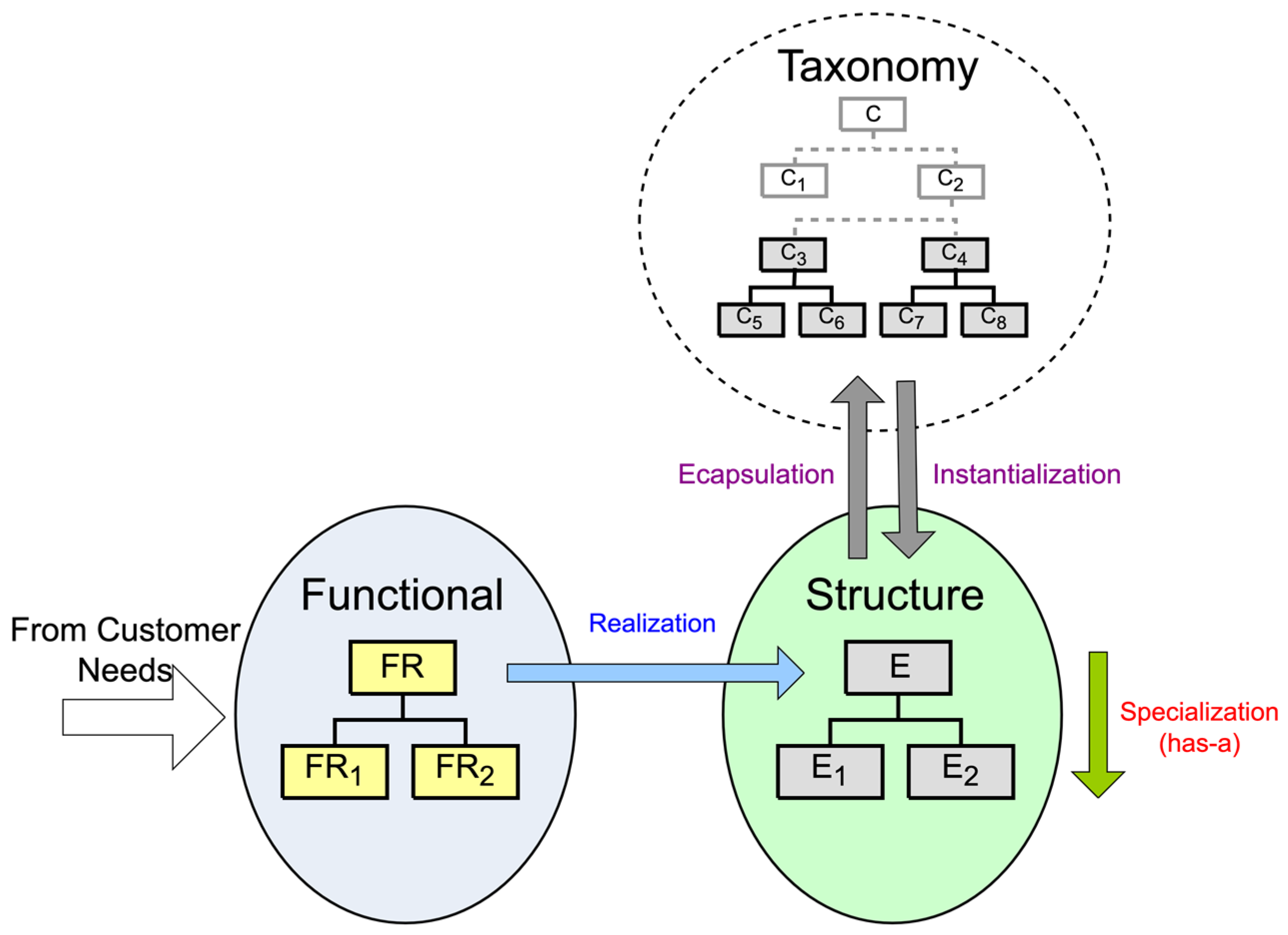
The SSDF aims to complement Object-Oriented (OO) software system design and contains customer, functional, structure, platform, taxonomy, and library domains. Because the SSDF is derived from the forward synthesis model (see
Figure 1), the critical design process is within customer, functional, and structure domains. More importantly, the forward synthesis model implies that the derived framework is not limited to OO software design. In other words, we extract the critical part that is defined according to the forward synthesis model from the SSDF, and the selected part should not be limited to OO software.
A functional requirement (FR), which presents the designer’s abstract wish—what the designer wants from the system—is the element in the functional space. It is chosen by the designer to satisfy the customer’s needs and should be described as a “to + verb”. For example, the customer wants to keep and show their photos. To fulfill this, a function can be “to save the photo files”. While the FR is decided, top-down specialization decomposes the upper-level FR into a sub-level FR. This top-down specialization maintains “abstraction” and all FRs form a hierarchy. This hierarchy maintains a “has-a” or “part-of” relationship.
Every entity should be a physical component or a software element in the system. For example, a wheel is one of the entities in a car system or a button in the user interface is the entity in the software system. Each one inside the structure domain is formed to realize the corresponding FR.
Realization between functional and structure spaces is not just simple horizontal mapping; instead, a “zigzagging” maneuver between the functional and structure domains is used. The “zig” operation, which horizontally maps the function to the same level of the entity by thinking of what element realizes the function, creates a “mean-of” dependency between the functional and structure domains. The “zag” operation, which gives the additional constraints from the upper entity to the sub-level function, guides the sub-level vertical functional decomposition. This constraint tells us that the property of the chosen entity limits the way we decompose the function. For example, if the designer chooses the brake as the entity for realizing the function “stop the wheels”, the additional constraints for its sub-level function could be “something attached on the axis”. Therefore, the functional decomposition in the functional space is often limited to the upper-level entity that the designer creates. This additional constraint is different from the system’s overall constraints, such as development time, costs, and resources; it originates from what entity the designer decides.
The taxonomy domain is a collection of some entities from the known world. Each element in the taxonomy space comes from two sources. An element can be a class, a module, or a package, which extracts the common part of the already-created entities in the structure domain. It can also be existing libraries or components provided externally. All the elements inside the taxonomy space are treated as background knowledge for reuse in designs; that is, each entity in the structure space can be a usage of its corresponding class.
3.2. PASTA
PASTA is an approach that formally and precisely models complex processes in a graphical and systematic presentation. It was later extended for code generation in software automation because of the use of a state machine. A PASTA model contains three hierarchies: role, artifact, and activity (or process). In a hierarchy, the lower elements are grouped into their direct upper-level element. The artifact and activity use a state machine to describe its transition precisely. The following explains the key elements of the PASTA model.
A role presents a unit of responsibility and indicates “who” can work on an activity. For example, in a software system, an administrator is a role that handles configuration.
Artifacts are final or intermediate work products (e.g., documents or codes) or information. Regarding software design, artifacts can represent things (e.g., objects, modules, or components) in a system.
An artifact state indicates the condition or status of the artifact. An artifact state change is a result of a performed activity.
Activities mean “doing” something. Lower-level activities (i.e., child) can be grouped into a higher level one (i.e., parent). For example, an activity, sending a translated message, contains two sub-activities, translating and sending the message.
The state machine is also applied to describe the situation of a process. The process state depends on the state of the artifact that is operated during the activity.
At the lowest level of the hierarchy, an activity can be specifically noted as an “operation” or “action”.
The primary association between roles, artifacts, and activities is that an actor (under a role) performs an activity on an artifact. Hence, if we describe a complete relationship, roles are subjects, activities are verbs, and artifacts are objects.
3.3. SSSDA
We combine how to use the SSDF to realize entities—zigzagging between functional and structure domains—and how to specify an artifact’s state changes in PASTA to create our proposed approach. The artifacts in PASTA can be considered entities in the structure domain in the SSDF because both can be software modules, objects, or components. As a result, artifact states are entity states.
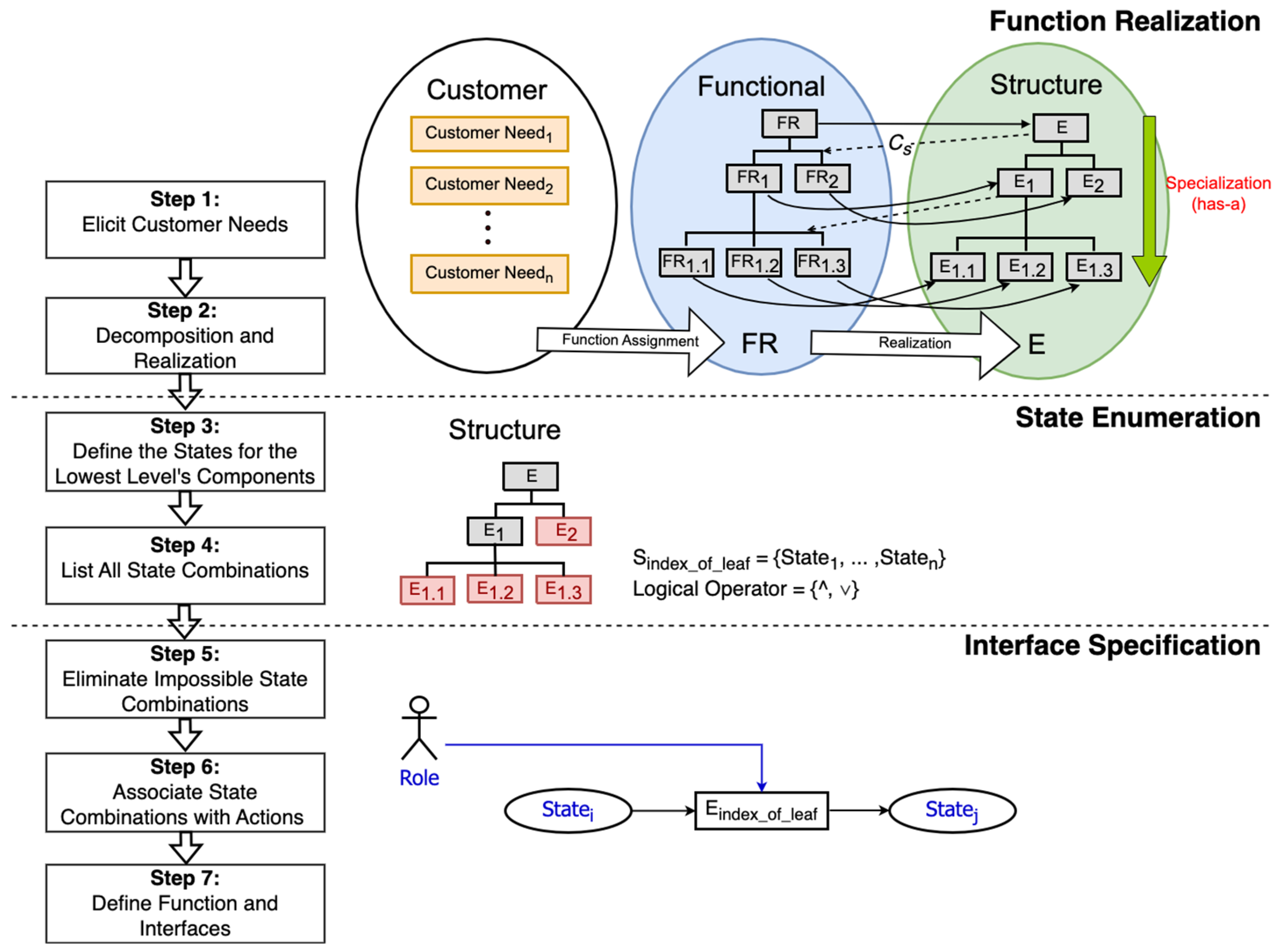
Using our proposed approach in designing embedded systems, the designer must go through seven main steps (see
Figure 2). In Step 1, customer needs are elicited after meeting with customers. Then, in Step 2, the designer applies zigzagging to derive the functional requirements and corresponding entities (e.g., modules or components). The horizontal arrows display how a designer decides on an entity from considering a functional requirement at the same level. The dotted arrows (i.e., Cs) constrain a designer’s reasoning while producing a lower-level functional requirement. After these two steps, modules or components of the to-be-designed system should be specified clearly.
The lowest entities, for example, the red node in
Figure 2, are leaf nodes in the structure hierarchy. In Step 3, the designer specifies the states of these leaf nodes. Equation (1) defines all the entities whose states need to be further defined, and the
L is the total number of them (see Equation (2)). All the possible states coming from these leaf nodes should be listed by the designer at the end of Step 3. Equation (3) shows all states, where
presents a set of states
at node
i and
i is equal 1 to
L.
Step 4 combines states from all the leaf entity nodes and lists all the combinations. Conjunction and disjunction can be used to connect two entity nodes’ states, as shown in Equations (4) and (5). We know that “two” possible logical operations must be considered when we calculate the number of total possible combinations.
The total state combination
TSC can be calculated from Equation (7) when we know the number of all the possible states for an individual entity
i (see Equation (6)). For example, if we only have entity leaf nodes 1 and 2 concerning total numbers of states
j1 = 2 and
j2 = 3, the total state combination
TSC is 12.
This bottom-up approach for specifying states of the embedded system might result in many possible states. Under certain situations, it could be self-evident that the disjunction can be eliminated, so Equation (7) becomes Equation (8). Because
TSC is all the possible states, in Step 5, we remove those impossible states after examination on all use cases.
In Step 6, states should be associated with actions first. Then, functions and interfaces should be defined accordingly. When the designer thinks of functions and actions, they determine who can perform those actions or functions. This step starts with identifying events, processes, or operations that will change an entity’s state. A role is an actor (e.g., system or user) who permits the execution of a function or an event on the entity. For example, we can identify a sensor’s state change from the “system” (role) “detecting the voltage change” (event) on a “sensor” (entity). In the last step, Step 7, according to the specified events or functions, the team further defines interfaces, parameters, and data for communications between internal parts or external systems.
After seven steps, the developer clarifies all the embedded system states, modules, events or functions, and roles. Because modules and associated events or functions are specified, the required components or libraries that need to be included in the modules can be identified. This result assists developers in later implementations and testing.
3.4. Implications on Architecture Model of SSSDA
The Krunchten’s 4 + 1 view model encompassed scenarios, logical, development, process, and physical views to describe software architecture [
58]. This generic approach reminds engineers to examine a system’s architecture but offers no operational details to produce each view. In contrast, our proposed SSSDA lets engineers follow its design thinking directions to produce views of the embedded software. The SSDF already demonstrated its guide to create those views documented as UML diagrams, thus forming scenarios between customer and functional domains, constructing logical, development, and process views among functional, structure, and taxonomy domains, and creating the physical view between structure and platform domains. Like the SSDF, the SSSDA can enrich design descriptions matching the 4 + 1 view model.
However, this study does not emphasize the platform domain, which is how physical views can be created. So, our later case study illustrating how to use the SSSDA does not exhibit any diagram associated with the physical view. Note that we do not enforce using UML diagrams to describe embedded software architecture and our embedded software project does not use an OO programming language. Hence, our demonstration will be shown by using block diagrams.
4. SSSDA Illustration by Case Study
A semi-automatic bandsaw developed by a sophomore student team is used to study how our proposed SSSDA works for inexperienced developers. The client’s primary need asked the student team to give the automatic movement to a bolt clamp attached to their bandsaw. Hence, the manual operations in their original cutting process can be reduced by precisely moving the clamp. However, moving the clamp is complicated. To consider safety in the factory, confirming the blade position is very important. The student team developed an attachment, which includes an embedded system and a mechanical part, adding to the client’s bandsaw. The produced embedded system controls the mechanical part to move a bolt clamp for cutting automatically.
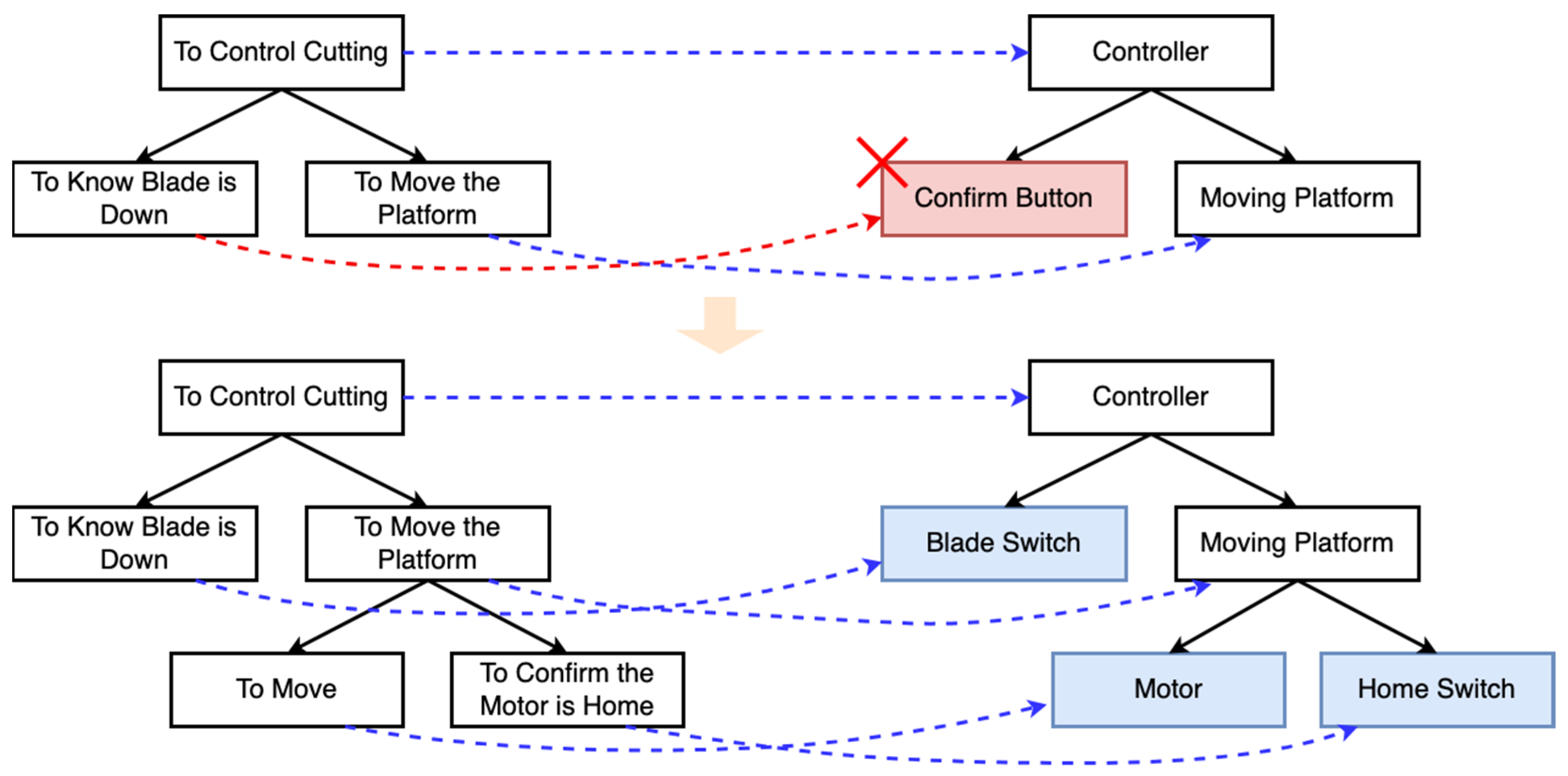
Figure 3 shows how the team, using the SSSDA approach, performed the zigzagging maneuver to lay out the embedded software’s entities (i.e., modules). The top-down force for driving specification enabled the team to gain specific details for functional requirements and design entities. During the zigzagging operations, the team understood that the higher-level entities might not have had any implementations and those entities presented a group of sub-entities. When the team decided on what entity should be used to realize the functional requirement, the team selected from a list of candidates. For example, for the functional requirement—“to know the blade is down”—the team could select a “confirmation button” or a “blade switch” as the design entity to satisfy the requirement. In the team’s final design result, the team chose a “blade switch” to detect if the blade’s position was down.
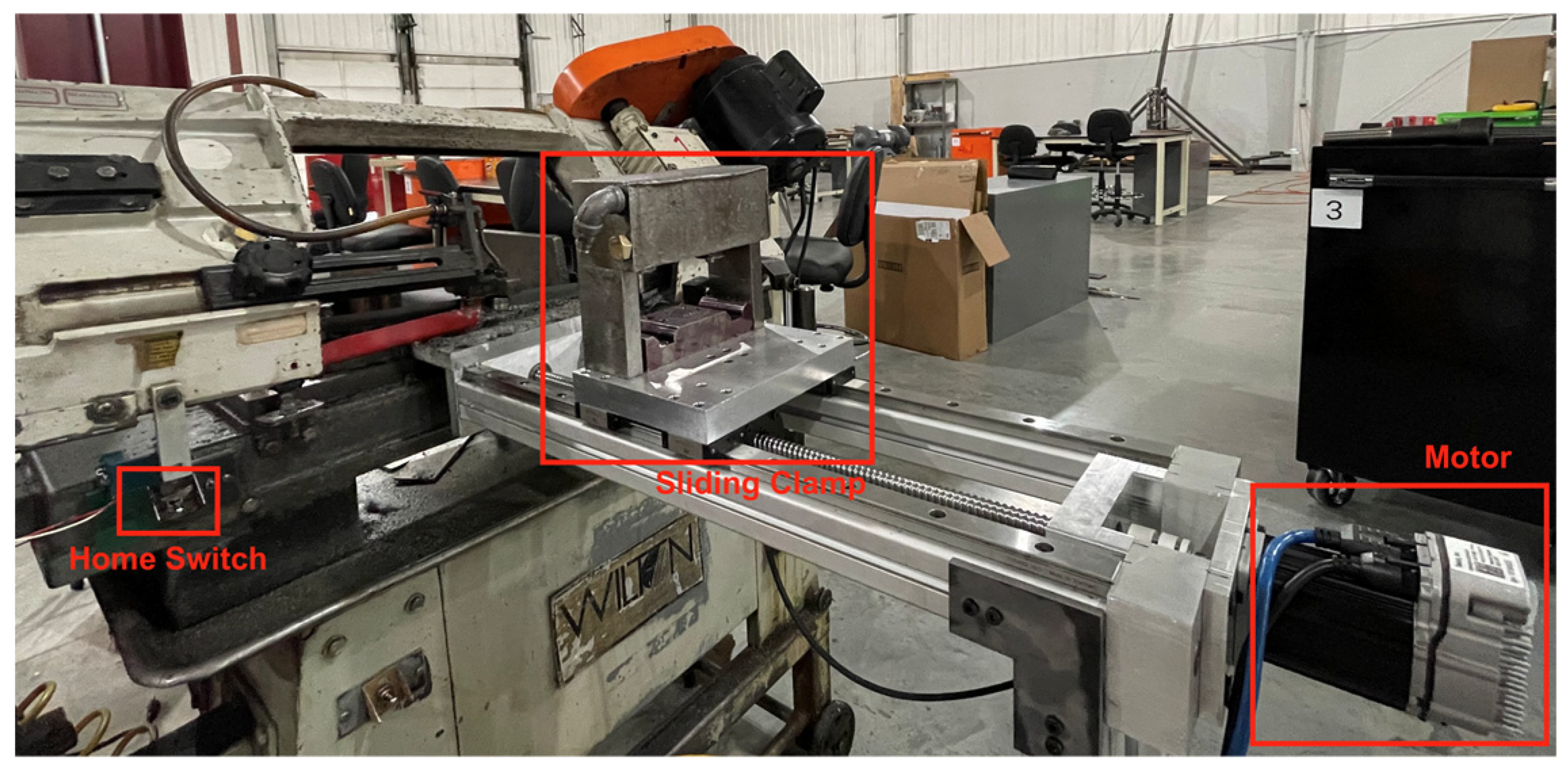
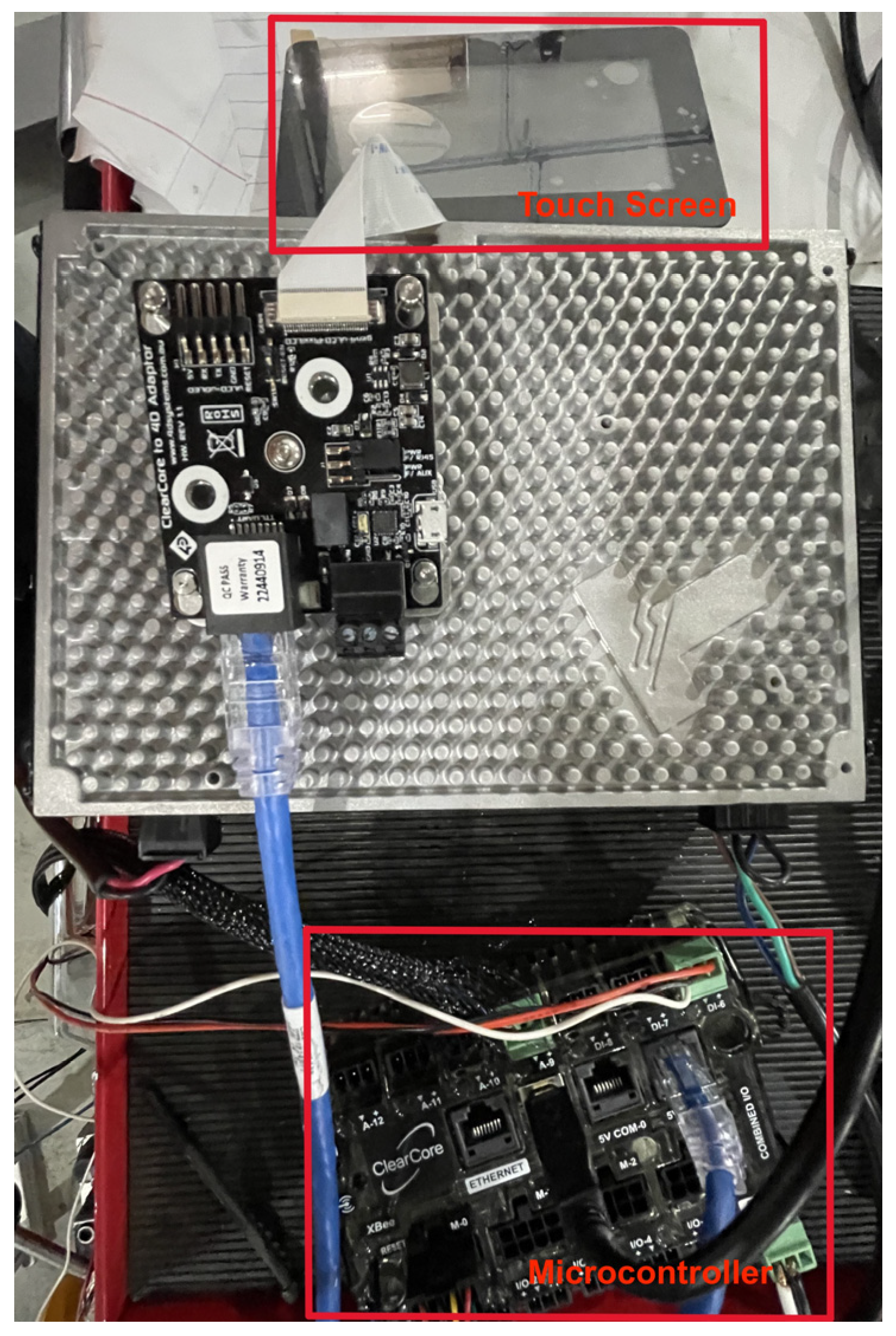
After investigating the available products on the market, the team decided to use a Teknic ClearCore microcontroller board for controlling every piece of the system, a 4D System touch screen for user input, a Teknic ClearPath servo motor for moving the clamp, and digital and analog switches for detecting positions. The ClearCore is a programmable microcontroller board that has digital and analog pins and communication ports, such as serial or ethernet ports. The students can write C programs to control connected parts, like the ClearPath servo motor.
Figure 4 and
Figure 5 show the built semi-automatic bandsaw.
Table 1 shows the entities and their corresponding states from
Figure 3. The design entity in the real-world implementation may be associated with a component that provides events, functions, or triggers. For example, a motor component provides “move” and “stop” functions. In the design result, the blade position sensor is a digital trigger that sends out 0 and 1 to indicate “open” and “close” so that the system can detect if the blade is down (i.e., close) or up (i.e., open). The team identified the states of the blade position sensor as BLADE_DOWN and BLADE_UP. Regarding the home position sensor, instead of using a digital one, the team selected an analog trigger because position detection with higher precision was expected. The voltage change due to the trigger was recorded in the microcontroller board. This voltage change was translated to states AT_HOME and NOT_HOME. The motor’s states considered two key factors in the system design, moving and positioning. The motor could stop or move at any location. Since the cutting position is the one that the system cares about, to interpret this, the motor’s states could be further divided into MOTOR_STOPPED, MOTOR_MOVING, IN_CUT_POSITION, and NOT_IN_CUT_POSITION.
There are 16 state combinations because the system only considers conjunctions between different entity’s states. However, a few state combinations are impossible because two states cannot happen simultaneously. For example, a block cannot be moved by the motor and at the cutting position at the same time (i.e., MOTOR_MOVING and IN_CUT_POSITION).
The entire system states can be presented as all the state combinations in
Table 2 after the team eliminated impossible state combinations. The team could use the result to validate the requirements—how the user will use the bandsaw. For example, the No. 4 state combination is the initial state of the built bandsaw and the No. 2 state combination means that home is the cutting position. Validating requirements by using state combinations is critical. This kind of bottom-up method overcomes the drawback of the traditional approach because identifying system states by viewing the system as a whole may omit some states of its components. These system states are not completely designated.
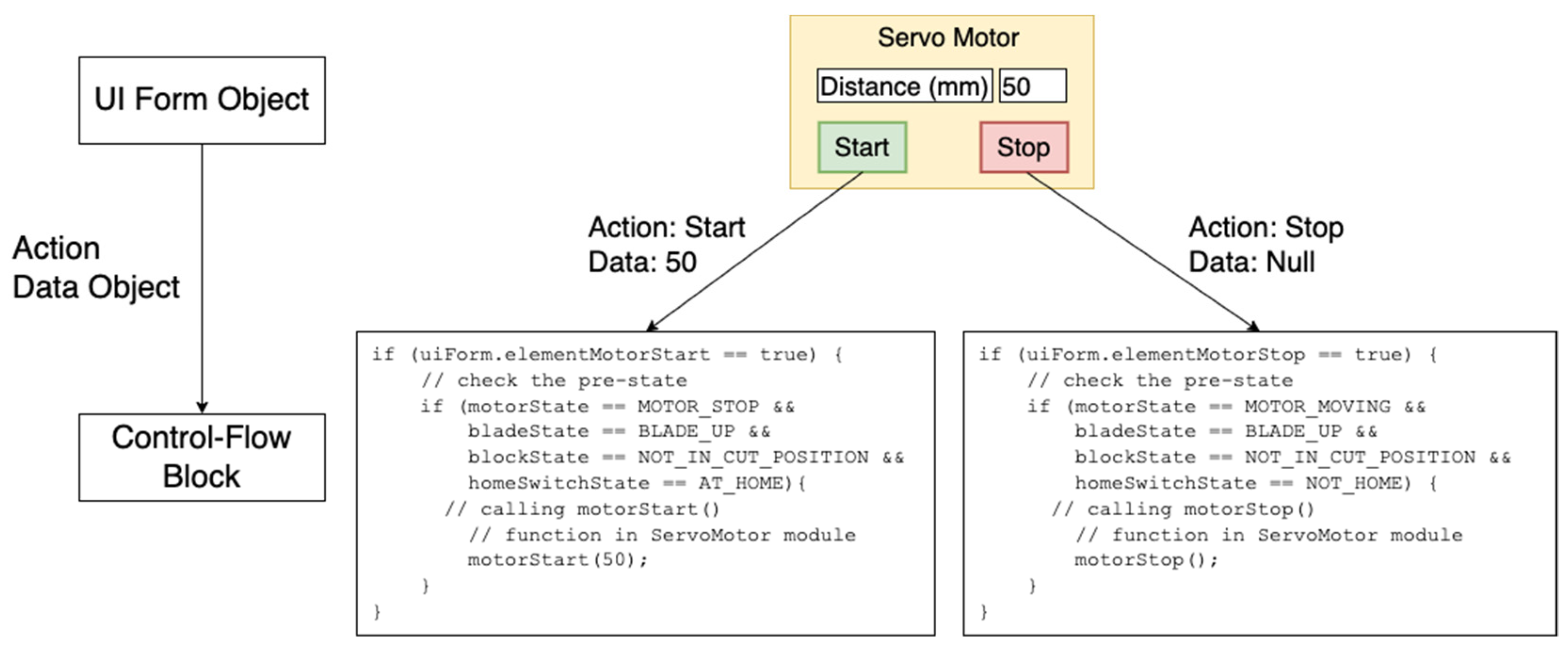
Having states of each component set the starting points for the team to think about how the actions or events triggered the component’s state changes. The actions or events could be further converted into functions or user interface events in the implementation. The function also contained existing libraries. For example, one of the ClearCore’s C libraries, analog pin reading function, measures a sensor’s voltage, and its voltage shifts can be programmed into the states of the sensor by the developer. User interface events like button clicks are a user’s actions triggering state changes, such as clicking on the “Stop” button (i.e., action) which calls the motor library’s function to stop the motor’s movement (i.e., motor’s state change).
Figure 6 demonstrates the codes and user interface design, which are implemented by the developer to control the sliding clamp block’s movement. Note that the pre-condition for the state action caused by the action is already specified from the state combinations shown in
Table 2.
From the illustration, we emphasize that the bottom-up approach from entity states also supports how the designer thinks of the components and events in the user interface. It differs from traditional software design practices that often separate the client (user interface) and the control first. Our proposed approach lets the developer design the user interface later in the development.
5. Result
5.1. Development
The entire embedded software development process can be divided into two major stages. In the first stage, the team designed and developed the software using the traditional software design method and system states. In the second stage, the team used the proposed SSSDA to design and implement the system. In both stages, the team conducted design and code reviews with instructors. During the review, the team members needed to describe their design and decisions, explain how requirements are satisfied by their design, and show how the implementation maps the design and fulfills the corresponding requirement. Four instructors investigated their design and implementation rationales and evaluated their answers to the review questions.
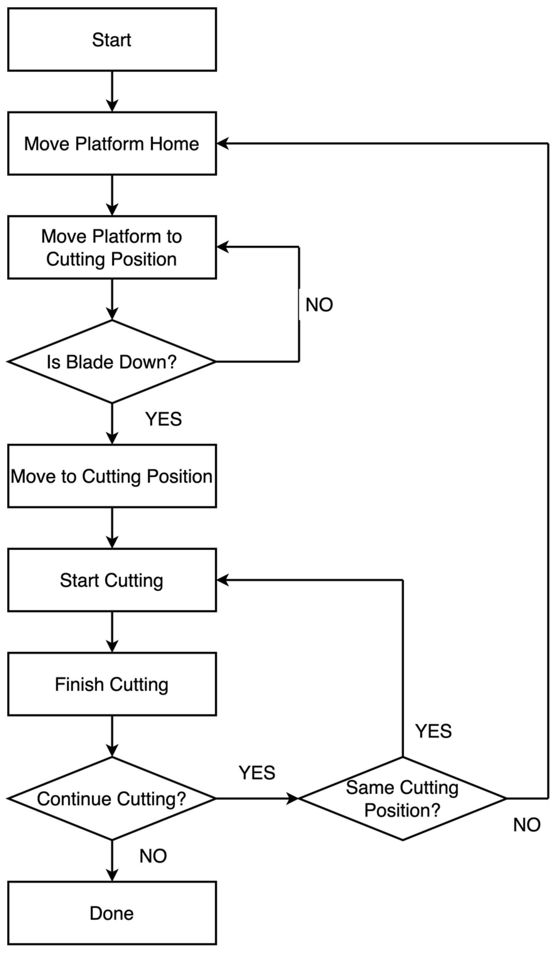
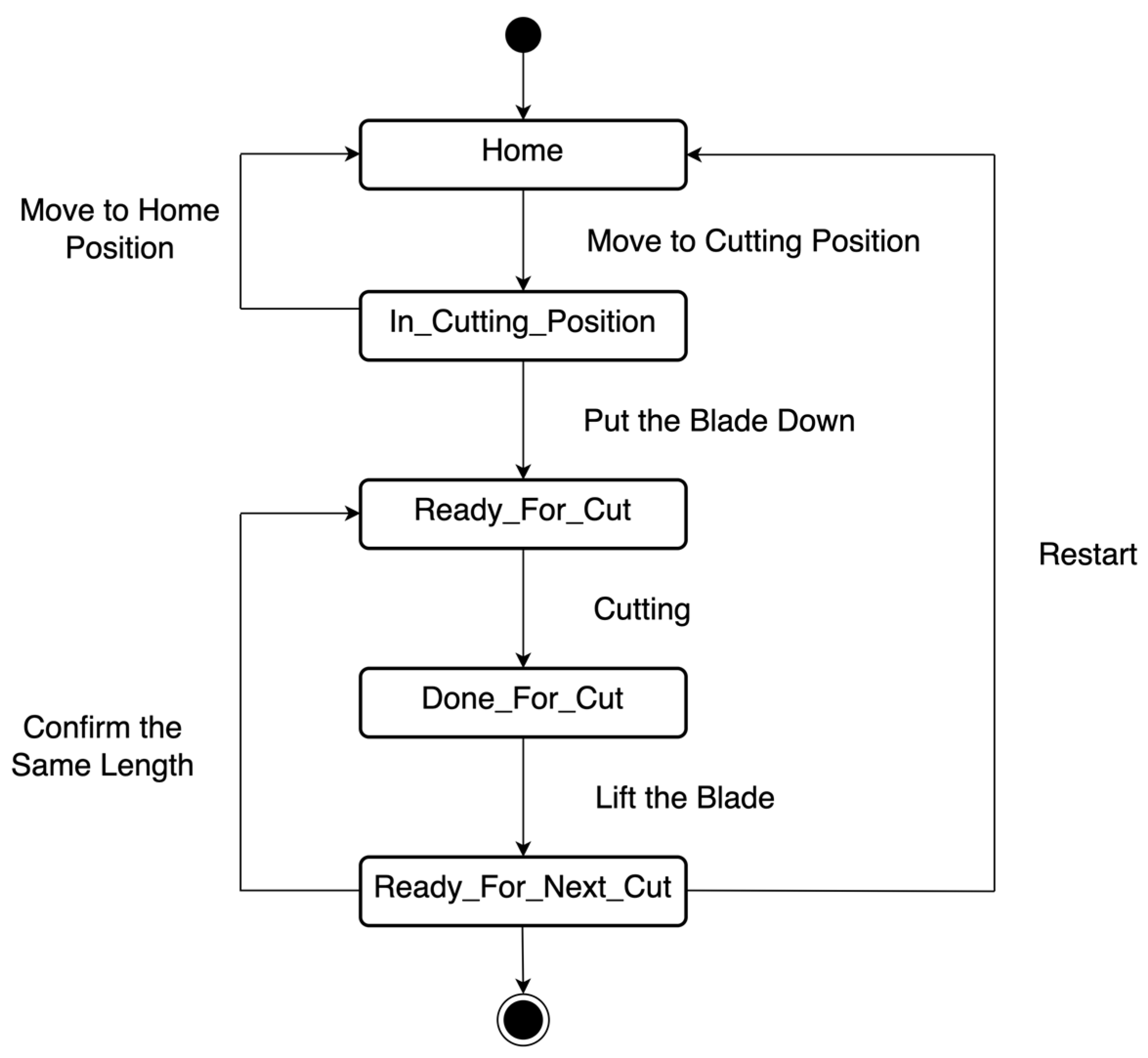
Figure 7 shows the flowchart after the team analyzed how the user should operate the semi-automatic bandsaw. The operations include lifting/putting down the blade, pressing the buttons on the touch screen, etc. The team used the same flowchart when they designed and implemented the embedded software in both approaches. Two straightforward discoveries are made while comparing both development results. First, the number of system states derived by the proposed method (see
Table 2) is more than the result of the conventional method (see
Figure 8). We find that some sub-states (or sub-element’s states) are embedded in certain system states in the conventional method. Second, from both implementations (see
Table 3), our proposed method produces more modules, functions, unit tests, and assertions than the traditional design approaches. In addition, our proposed method has fewer defects. The design and codes from our proposed method are articulated more precisely and clearly in the review. These comparisons can be found in
Table 4.
5.2. Discussion on Implementation
According to the investigations on the source codes, the team created two monolithic modules using the conventional method. One module for controlling the main flow contains a large and complex function—namely, process(). The process() function uses many multi-level (i.e., five levels at most) nested ifs to determine how system operations should proceed. In contrast, each module in the resulting codes of the proposed approach determines its states. To maintain the primary flow, the main control module detects other modules’ states, such as home switch detecting if the sliding clamp block reaches the home position. In this way, the main control module becomes less complex since many nested ifs have few levels—three levels at most. Because more modules and functions are created, the number of total lines of code becomes higher.
The structure in the proposed design approach’s result also enables reuse because modules and functions are independent. The conventional approach’s implementation is sequential. In other words, any part of the main control module cannot be divided independently.
5.3. Discussion on Testability
Many potential factors affect testability, so many testability definitions exist [
59,
60]. From McCall’s [
61] and Boehm’s [
62] models, we can measure testability based on how simply the module can be tested separately and how easy it is to validate requirements met by the implemented software.
Increasing modularity in the proposed approach’s result also helps testability. The team could easily define unit tests to examine the expected output of the function in the proposed approach’s results. However, with the conventional method’s result, the team could not simply define unit tests. Therefore, they had to develop an unprofessional testing strategy. This strategy tries to test a piece of continuous statements by printing out the variable’s value. Therefore, the team split the monolithic function into several pieces, taking out those pieces that are not targeted for testing, and then inspected the printing results at each piece. This procedural-like method was used due to the sequential implementation. As a result, we could infer that testability is better in our proposed method. More importantly, more unit tests constructed in the proposed method can be regarded as a result of good modularity.
5.4. Discussion on Defects
The proposed approach’s implementation has fewer defects from the review with instructors. One possible reason is that the team already knew how to avoid defects after implementing the conventional design. However, we also argue that having fewer defects could also have resulted from clearer and independent module separation because it was easier for the team to find what responsibility a function had and what functionalities a module should have provided. We think that our approach makes their codes more readable.
This interpretation can also be supported by the instructor’s evaluation of how students express their implementation and design. Showing better assessment results on code explanations and design descriptions mean that the team could describe the purpose of each line of code and the rationale of the function or module designed more clearly. Therefore, we think structures and states produced by our proposed approach made their codes more comprehensible, which resulted in few defects.
One additional finding in the comparison is about how the team used the proposed method to discover a safety defect. The team stuck with using a button to allow the moving clamp block because they followed the flowchart and constrained themselves in thinking about the solution. This could have been the outcome of using system states since the team already limited their solution to the touch screen. Nevertheless, two-dimensional decomposition helped the team select what entity could realize the function; in this way, the team expanded their solution space and came up with a higher safety design.
6. Discussion and Limitations
Our study only examines a relatively smaller project, so the scalability of the SSSDA could be a concern. Increasing the number of states and entities can make the SSSDA unmanageable due to the large number of state combinations. However, we expect this scalability can be improved by using a tool. That is, the tool can automatically generate state combinations and assist in the elimination of impossible combinations. This also shows an advantage of the SSSDA; that is, it can promote partial automation due to its systematic feature.
Another limitation concerns validation on the result of fewer defects. While conducting reviews can help us discover potential causes for fewer defects, we must take into account the impact of students’ prior experiences with the same project to ensure accurate validation.
7. Conclusions
We proposed the SSSDA to guide design reasoning in a systematic way, which complements existing design methods and thinking in embedded software development. Our illustration shows how to make more rational decisions on decomposition in the structure domain, combine individual states, and remove impossible state combinations. Our observations on students’ usage showed that the SSSDA helps them utilize states, combine various states, eliminate impossible state combinations, and specify modules for the entire system. This led to less coupled, more testable, and less defective implementation after comparing both design results. We also understand the limitations to our validation of defects. Students can learn the knowledge of the project when they first apply the conventional method. From the overall consequences, we are still confident that our proposed SSSDA showed promising results in guiding inexperienced developers to create modules and define states to design embedded systems.
8. Future Work
Work can be carried out in the future regarding improving the validation of design results, investigating the scalability of the SSSDA, and adding more details on producing UML diagrams in various architectural views. To reduce the bias in the validation, we can compare the result of the same system design from control and experimental groups, which are formed by a random selection of students. We also believe that our approach can be expanded to software automation to increase the scalability. A graphical tool can be developed for developers to build up the model of our proposed approach. It can also generate the source codes and verification scripts once existing libraries and components can be imported and linked to the designed entities. An analysis can be carried out on a large-scale system to understand the scalability of the SSSDA. We also expect to create examples of how to produce UML diagrams through domains of the SSSDA. Finally, we want to receive feedback on applying the SSSDA from experienced engineers in designing a complex real-world project.


