Proceeding Paper

Development of a Clock Generation and Time Distribution System for Hyper-Kamiokande †

by
Lucile Mellet
*,
Mathieu Guigue
,
Boris Popov
,
Stefano Russo
and
Vincent Voisin
on behalf of the Hyper-Kamiokande Collaboration
Laboratoire de Physique Nucléaire et de Hautes Energies (LPNHE), CNRS/IN2P3, Sorbonne Université, 75006 Paris, France
*
Author to whom correspondence should be addressed.
Presented at the 23rd International Workshop on Neutrinos from Accelerators, Salt Lake City, UT, USA, 30–31 July 2022.
Phys. Sci. Forum 2023, 8(1), 72; https://doi.org/10.3390/psf2023008072
Published: 18 January 2024

Abstract

:
The construction of the next-generation water Cherenkov detector Hyper-Kamiokande (HK) has started. It will have about a ten times larger fiducial volume compared to the existing Super-Kamiokande detector, as well as increased detection performances. The data collection process is planned from 2027 onwards. Time stability is crucial, as detecting physics events relies on reconstructing Cherenkov rings based on the coincidence between the photomultipliers. The above requires a distributed clock jitter at each endpoint that is smaller than 100 ps. In addition, since this detector will be mainly used to detect neutrinos produced by the J-PARC accelerator in Tokai, each event needs to be timed-tagged with a precision better than 100 ns, with respect to UTC, in order to be associated with a proton spill from J-PARC or the events observed in other detectors for multi-messenger astronomy. The HK collaboration is in an R&D phase and several groups are working in parallel for the electronics system. This proceeding will present the studies performed at LPNHE (Paris) related to a novel design for the time synchronization system in Kamioka with respect to the previous KamiokaNDE series of experiments. We will discuss the clock generation, including the connection scheme between the GNSS receiver (Septentrio) and the atomic clock (free-running Rubidium), the precise calibration of the atomic clock and algorithms to account for errors on satellites orbits, the redundancy of the system, and a two-stage distribution system that sends the clock and various timing-sensitive information to each front-end electronics module, using a custom protocol.

1. Introduction

1.1. Context

The Japanese accelerator-based long-baseline neutrino oscillation experiment, called T2K [1], has been running since 2010. It consists of a muon neutrino (or anti-neutrino) beam with energy peaked around 600 MeV produced at Tokai by the J-PARC accelerator facility [2], characterized by a near detector and reaching an off-axis Cherenkov far detector (Super-Kamiokande) after a baseline of 295 km at the Kamioka site. In the Super-Kamiokande (SK) detector [3], neutrinos have weak interaction with nucleons (mainly via charged-current quasi-elastic interaction) and can produce a charged lepton with energy above the Cherenkov threshold. The walls of the far detector are covered with photomultipliers which allow us to detect the emitted Cherenkov light. T2K aims at measuring flavor oscillation probabilities. The flavor of the interacting neutrino event can be inferred from the Cherenkov light pattern of the corresponding emitted charged lepton.
The future of Japan’s long-baseline neutrino programs is being prepared. Concerning T2K, there is an ongoing upgrade of both the J-PARC beam and the near detector, but most importantly at long term, the construction of a new far detector Hyper-Kamiokande (HK) [4] on the symmetric site to SK with respect to the beam axis (same off-axis angle). It will be based on the same technology as SK, but eight times larger and with new photomultipliers (PMTs), a new digitizer, and a new timing system which will be the main topic of this paper. With the start of the data collection planned for 2027, the increased statistics and performance of HK will allow for the measurement of the CP violation phase, the determination of neutrino mass hierarchy, higher precision in measuring the atmospheric neutrino oscillation parameters, and will open the door to other neutrino detection challenges such as Supernovae bursts and diffuse background, or neutrinos’ time of flight measurements as in [5].

1.2. Timing Needs and Requirements

We will now focus on the design of the timing system for HK, which will play an important role in achieving the goal described previously. The lepton flavor identification depends on the reconstruction of the Cherenkov ring patterns (a sharp ring being the signal for a muon and a fuzzier one for an electron). The particle interaction vertices are reconstructed through the relative photon arrival timing between the PMTs. As a result a very good internal synchronization between all PMTs is needed and has been quantified to a stability under 100 ps, in relation with other reconstruction limitations. In addition, an external synchronization using GNSS-based time (or tags) is required to align to the accelerator site to open time windows to record all data when the neutrino beam goes through HK, but also to align to universal time UTC in the context of multi-messengers astrophysics. For instance, in case of a supernova burst, UTC synchronization can allow different neutrino observatories to point to the right region of the sky if the timing precision is sufficient for efficient triangulation. To achieve this, it is required to monitor HK timing with respect to UTC within 100 ns at least.

2. Materials and Methods

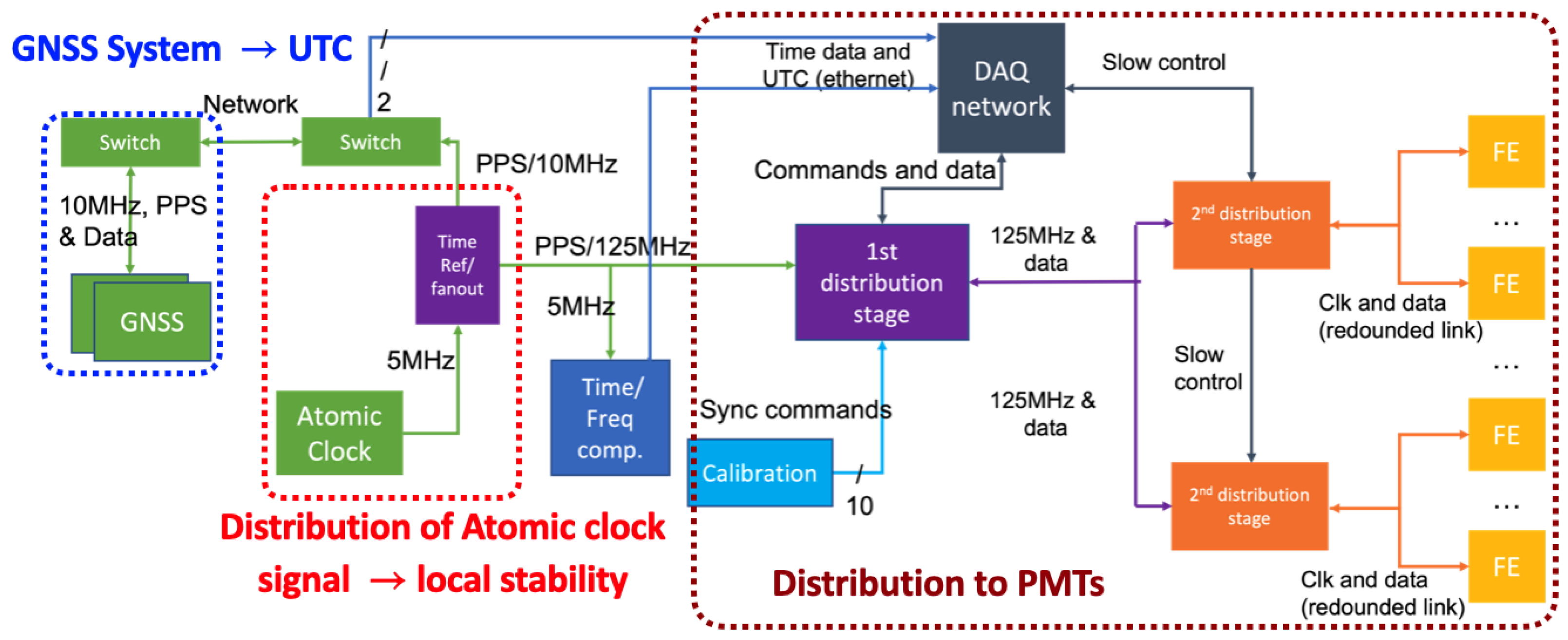
2.1. Proposed Solution

The proposed solution that we describe here is structured around one single time reference point and implements known standard metrology techniques [6,7,8]. This reference point distributes a high-frequency clock signal built from an atomic clock. This ensures short-term stability of the time signal as it will be shown later. The system will integrate a GNSS (GPS + other satellite constellations) antenna (B3E6 choke ring [9]) and receiver (Septentrio PolaRx5 [10]) to provide the link to the GNSS time base and to UTC. The system will also include calibration and monitoring components and will distribute timing information to the PMTs and data acquisition system via a two-stage distribution. Finally, full redundancy of signal generation is foreseen in case of a faulty item. The detailed scheme of the proposed solution can be seen in Figure 1.
The reason for this choice is that atomic clocks are the best solution for stability at short term (typically hours to days) because their level of white noise is very low. However, they suffer from a long-term drift because of an inherent frequency random walk noise. They may also suffer from a deterministic quadratic drift that can be removed as a first step of analysis. The atomic clock used here is the most common frequency standard: the Rubidium clock (FS725 from Stanford Research [11]). Its performances already meet HK’s requirement. However, other more expensive and more stable clocks can be used such as Masers. On the other hand, signals from GNSS poorly behave at short term but do not possess the random walk component to their noise; hence, they become more reliable at long term. The idea is to combine both in HK’s system. The way the frequency stability can be measured is always against a reference known to be more stable and through a frequency counter. To represent this stability, the relevant statistical tool to use is the Allan standard deviation [12] which is given by
σ y 2 ( τ ) = 1 2 ( y ¯ n + 1 y ¯ n ) 2
It is the variance of the frequency ratio to nominal (y) as a function of the averaging, or sampling time ( τ ). This can be performed in the time domain as well. It allows us to show stability of the same signal on different time scales. In Figure 2, it can be seen that the Rubidium clock is indeed more stable than the signal from the receiver (lower white noise level) until a certain point (∼ 2 × 10 4 s ) where the long term drift becomes dominant. While averaging a white noise over a longer time decreases the deviation, it is not the case for a random walk noise. If we correct the clock signal with the GNSS information every 5.5 h only, we are able to combine both stability performances. Two types of references are available at the lab for the R&D process: a signal coming through the optical link from the official time-keeping lab in France: SYRTE laboratory, and a passive hydrogen maser, known to be more stable than the elements to characterize.

2.2. GNSS Receiver

As said before, a GNSS antenna and receiver are used. Once the exact position of the antenna has been established, it can be used as a time source. In this configuration, the selected receiver (PolaRX5 TR) will report on tracking all available satellites for 13 min and then directly compute a time difference between its local oscillator and the GPS time (only tested constellations in this study), taking into account all appropriate propagation delays (atmospheric, ionospheric, calibrated cables, antenna, etc.) and performing fits. An additional feature of particular interest for our system is that an external frequency (10 MHz and 1 pps signals) can be given as an input to this receiver so that it bypasses the local oscillator and directly returns the difference between that input signal and the GPS time, using the 10 MHz signal for the computation.

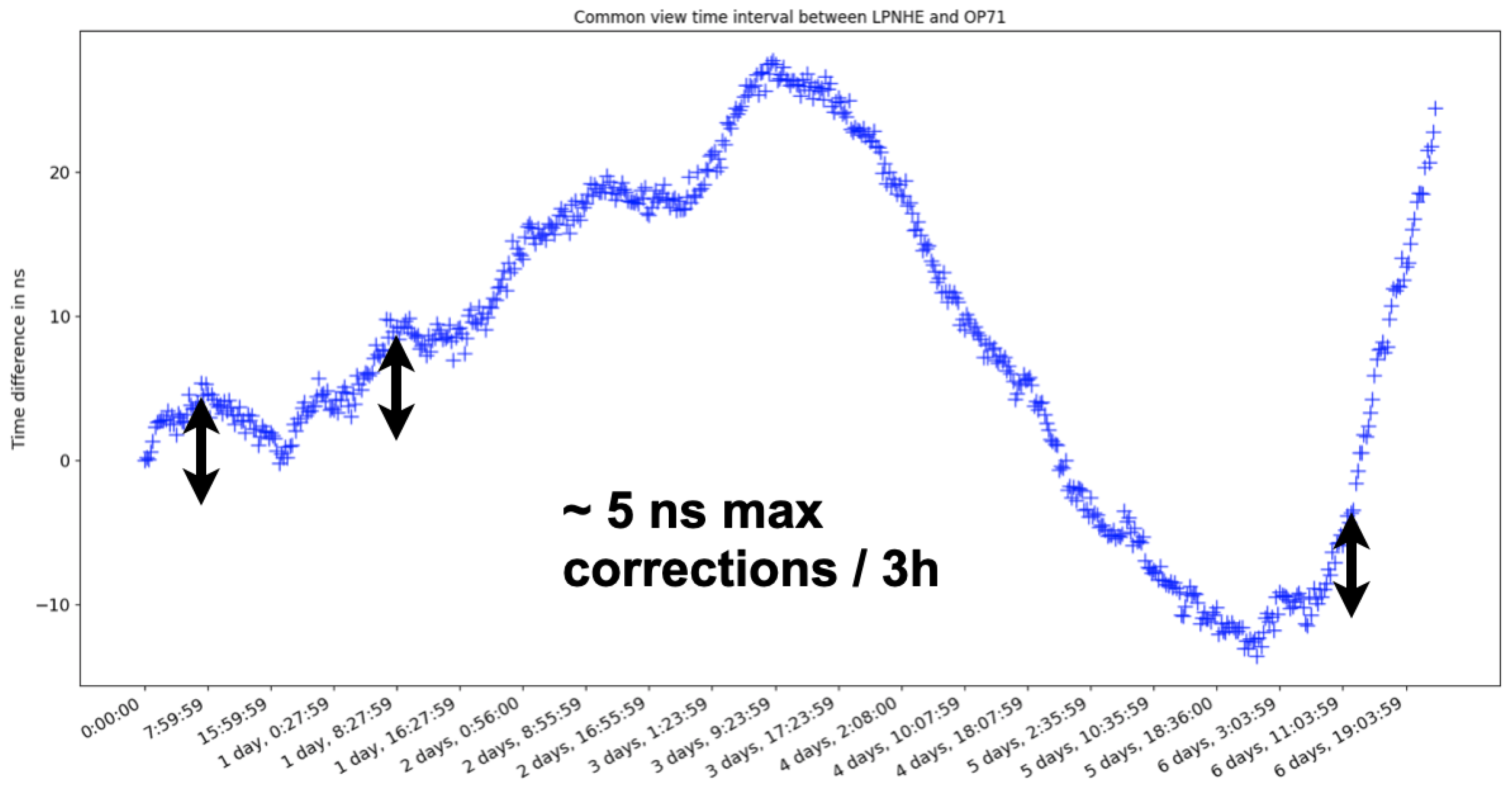
2.3. The Common-View Time-Transfer Technique

The output of the receiver is in a standard format called CGGTTS files [13], which contains all information about visible satellites, applied delays, as well as the time differences to monitor in 0.1 ns, which are computed from fits between each GNSS data point (each 13 min). The time differences given by the GNSS receiver do not directly give UTC time tags for events. The use of the standard “Common view technique” of time transfer (the software used is available here [14]) is therefore needed. In each country or region of the world, there is an official time-keeping lab in charge of the local UTC, which is SYRTE in France. This lab can provide CGGTTS files every day, obtained with the UTC signal, as an input to their receiver. One can use an algorithm that selects the satellites that were seen at both sites at the same time so that it cancels out the GPS time and obtains time differences between a specific system (here, it is our test set up) and the local UTC. Global UTC is made of all local UTCs with different coefficients and the correspondence is published every month, as shown in [15].

3. Results

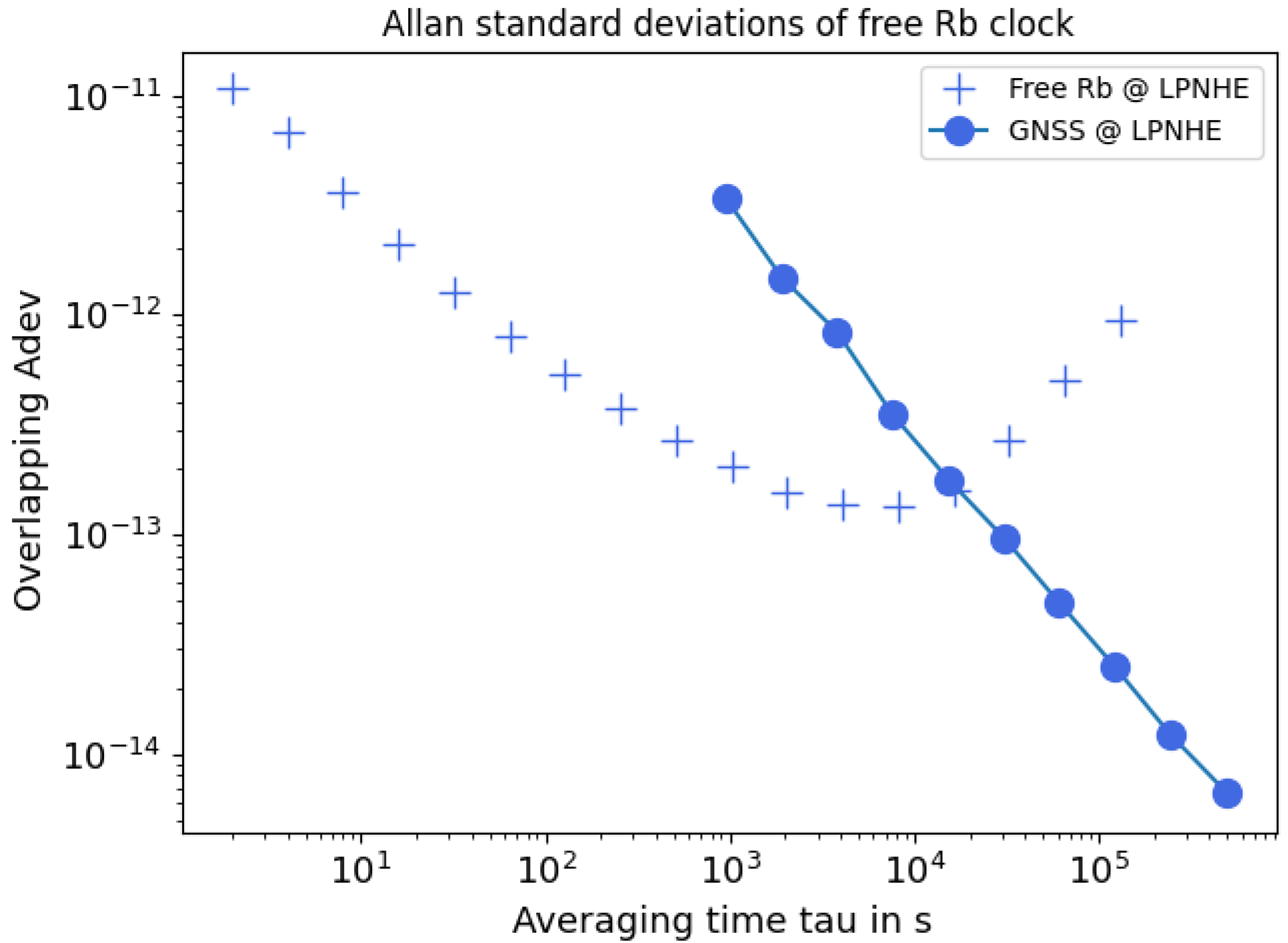
3.1. Clock Signal Generation

All individual components were calibrated and characterization was cross-checked with the expert lab SYRTE. The antenna is placed on the roof of LPNHE at Jussieu campus in Paris, France.
The clock generation part of the proposed solution has been tested at our lab. After the required cross-checks and calibrations, 6 days of data were taken with the Rubidium clock as an input to the receiver to monitor its signal with respect to the GPS time base. As mentioned before, the deterministic quadratic noise of the Rubidium clock is removed as a first step of the analysis. Common view was then performed with the French expert lab SYRTE and the remaining differences to French UTC can be seen in Figure 3. If corrections are applied on a timescale of 3 h, those would always be less than 5 ns, which gives a lot of margin for the system to stay within HK’s requirements. This result might be slightly underestimated because both our lab and the reference one are in Paris (1 km away from each other only), which will not be the case in real HK conditions. The way corrections will be applied is still in development; however, it will not be sudden jumps but smooth fits. Finally, because HK will be in a valley in a mountain area, the number of satellites available is a concern. It will mostly be limited by the minimum elevation angle that allows for a clear view to the sky. A rough estimation for the worst case scenario was 50°, and it was shown that in those circumstances in Paris, there are always at least two satellites, which is just enough.

3.2. Time Distribution

The time distribution system will be built in two stages, based on the same technology. First, a 96-port clock distributor will pass on the signal to the second stage, where about 70 modules will then distribute it to the front-end electronics. A total of 24 photomultipliers are connected to each front-end electronics. The distributor prototype was produced and the first tests show that the jitter level at second stage is of 40.6 ps, which can be reduced to 2.4 ps by filtering the signal with a Phase-Locked Loop. It is in good agreement with what is needed for the experiment.

4. Conclusions

As a conclusion, the R&D is entering its final phase for this proposed new timing system for Hyper-Kamiokande. The first results fall easily into the requirements even if they are not in full real conditions. Most of the work is now focusing on obtaining the best possible time precision with this system to expand the physics opportunities of HK.

Author Contributions

All authors participated in the conceptualization; electronics and technical development, S.R. and V.V.; analysis aspects, L.M., M.G. and B.P.; writing—original draft, L.M. All authors have read and agreed to the published version of the manuscript.

Funding

This research was funded by IN2P3/CNRS, the French “Agence nationale pour la recherche” under grant number ANR-21-CE31-0008, the “IdEx Sorbonne Université” and the 2019 “Sorbonne Université Emergences: MULTIPLY” grant.

Institutional Review Board Statement

Not applicable.

Informed Consent Statement

Not applicable.

Data Availability Statement

The data presented in this study are available on request from the corresponding author. The data are not publicly available due to ongoing analysis and R&D process.

Conflicts of Interest

The authors declare no conflicts of interest.

Abbreviations

The following abbreviations are used in this manuscript:
GNSSGlobal Navigation Satellite Systems
GPSGlobal Positioning System
UTCUniversal Time Coordinated
R&DResearch and Development
SYRTESYstèmes de Référence Temps-Espace (lab)

References

  1. Abe, K.; Abgrall, N.; Aihara, H.; Ajima, Y.; Albert, J.B.; Allan, D.; Amaudruz, P.-A.; Andreopoulos, C.; Andrieu, B.; Anerella, M.D.; et al. The T2K Experiment. Nucl. Instrum. Methods A 2011, 659, 106–135. [Google Scholar] [CrossRef]
  2. Abe, K.; Aihara, H.; Ajmi, A.; Alt, C.; Andreopoulos, C.; Antonova, M.; Aoki, S.; Asada, Y.; Ashida, Y.; Atherton, A.; et al. J-PARC Neutrino Beamline Upgrade Technical Design Report. arXiv 2019, arXiv:1908.05141. [Google Scholar]
  3. Fukuda, S.; Fukuda, Y.; Hayakawa, T.; Ichihara, E.; Ishitsuka, M.; Itow, Y.; Kajita, T.; Kameda, J.; Kaneyuki, K.; Kasuga, S.; et al. The Super-Kamiokande detector. Nucl. Instrum. Methods A 2003, 501, 418–462. [Google Scholar]
  4. Abe, K.; Abe, K.; Aihara, H.; Aimi, A.; Akutsu, R.; Andreopoulos, C.; Anghel, I.; Anthony, L.H.V.; Antonova, M.; Ashida, Y.; et al. Hyper-Kamiokande Design Report. arXiv 2016, arXiv:1805.04163. [Google Scholar]
  5. Abe, K.; Adam, J.; Aihara, H.; Akiri, T.; Andreopoulos, C. Upper bound on neutrino mass based on T2K neutrino timing measurements. Phys. Rev. Am. Phys. Soc. 2016, 93, 012006. [Google Scholar] [CrossRef]
  6. Lombardi, M. Fundamentals of Time and Frequency. In The Mechatronics Handbook; CRC Press: Boca Raton, FL, USA, 2002; ISBN 978-0-8493-6358-0. [Google Scholar]
  7. Lombardi, M.A.; Nelson, L.M.; Novick, A.N.; Zhang, V.S. Time and Frequency Measurements Using the Global Positioning System. Cal Lab Int. J. Metrol. 2001, 8, 26–33. [Google Scholar]
  8. The OPERA Collaboration; Adam, T.; Agafonova, N.; Aleksandrov, A.; Altinok, O.; Alvarez Sanchez, P.; Anokhina, A.; Aoki, S.; Ariga, A.; Ariga, T.; et al. Measurement of the neutrino velocity with the OPERA detector in the CNGS beam. J. High Energy Phys. 2011, 2012, 93. [Google Scholar] [CrossRef]
  9. Septentrio Polant Choke Ring Antenna Web Page. 2021. Available online: https://www.septentrio.com/en/products/antennas/chokering-b3-e6 (accessed on 4 October 2022).
  10. Septentrio Polarx5tr Gnss Receiver Web Page. 2021. Available online: https://www.septentrio.com/en/products/gnss-receivers/reference-receivers/polarx-5tr (accessed on 4 October 2022).
  11. Stanford Research System fs725 Rubidium Atomic Clock Web Page. 2021. Available online: https://www.thinksrs.com/products/fs725.html (accessed on 4 October 2022).
  12. Allan, D.W. Statistics of Atomic Frequency Standards; IEEE: Piscataway, NJ, USA, 1966; Volume 54, pp. 221–230. [Google Scholar] [CrossRef]
  13. Defraigne, P.; Petit, G. CGGTTS-Version 2E: An Extended Standard for GNSS Time Transfer. Metrologia 2015, 52, 6. [Google Scholar] [CrossRef]
  14. Available online: https://syrte.obspm.fr/spip/services/ref-temps/article/logiciel-de-raccordement-a-utc-op (accessed on 4 October 2022).
  15. Available online: https://www.bipm.org/en/time-ftp/circular-t (accessed on 4 October 2022).
Figure 1. Detailed scheme of the proposed timing system for HK (redundancy not included).
Psf 08 00072 g001
Figure 2. Overlapping Allan standard deviation (ADEV) for the free Rb clock and the GNSS receiver.
Psf 08 00072 g002
Figure 3. Evolution of time differences between the Rubidium clock (deterministic drift removed) and French UTC via GPS signals over 6 days.
Psf 08 00072 g003
Disclaimer/Publisher’s Note: The statements, opinions and data contained in all publications are solely those of the individual author(s) and contributor(s) and not of MDPI and/or the editor(s). MDPI and/or the editor(s) disclaim responsibility for any injury to people or property resulting from any ideas, methods, instructions or products referred to in the content.

