
A Demonstrator for Muon Ionisation Cooling †


Rutherford Appleton Laboratory, Didcot OX11 0QX, UK
†
Presented at the 23rd InternationalWorkshop on Neutrinos from Accelerators, Salt Lake City, UT, USA, 30–31 July 2022.
Phys. Sci. Forum 2023, 8(1), 37; https://doi.org/10.3390/psf2023008037
Published: 11 August 2023
Abstract
:The muon collider is an excellent prospect as a multi-TeV lepton collider, with the possibility for high luminosity and reaching 10 TeV or more. In order to realise such luminosity, high beam brightness is required. Ionisation cooling, which was demonstrated recently by the Muon Ionization Cooling Experiment (MICE), is the technique proposed to realise sufficient brightness. MICE demonstrated transverse emittance reduction of incident beams having relatively high emittance and without beam reacceleration. The international Muon Collider Collaboration proposes a Demonstrator for Muon Cooling that will demonstrate six-dimensional emittance reduction over a number of cooling cells, operating at beam emittance close to the ultimate goal for the muon collider. Together with a full R&D programme, this will pave the way for the construction of a muon collider. In this paper, initial considerations and possible implementations for the Demonstrator are discussed.
1. Introduction
The muon collider is an excellent candidate for an energy frontier collider [1]. Unlike protons, muons are fundamental particles so that all of the collision energy is available to form products, enabling access to relatively high-energy physics processes. The relatively high muon mass compared to electrons means that muons do not emit much synchrotron radiation so that they can be accelerated in rings, enabling a compact facility to be constructed compared to an electron–positron collider at the same energy.
In existing facilities, muons are created as products of proton collisions on a target. The muons produced have a large beam emittance and must be cooled. Muons have a short lifetime, approximately 2.2 s, and the cooling must be achieved before decays reduce the beam intensity prohibitively.
A cooling system has been proposed as a part of the Muon Accelerator Programme using ionisation cooling [2]. In ionisation cooling, muons are passed through an energy-absorbing material [3]. The muons ionise the absorber material, reducing the total momentum of the beam. The muons are subsequently reaccelerated in RF cavities, restoring the longitudinal momentum of the beam. Overall, the transverse beam emittance is reduced.
Multiple Coulomb scattering of muons off the atomic nuclei spoils the ionisation cooling effect. Absorbers having a low atomic number tend to remove more energy relative to the amount of scattering and, so, perform better. A tight focus on the absorber increases the transverse momentum of the beam, so that the relative impact of the scattering is reduced.
Longitudinal emittance can be removed by introducing a position–energy correlation (dispersion) into the beam using dipoles. Suitably arranged wedge-shaped absorbers can be placed so that the higher energy part of the beam passes through the thicker part of the wedge. The position–energy correlation is cancelled by the wedge. This process effectively moves emittance from the longitudinal phase space to the transverse phase space, where the ionisation cooling process outlined above removes the emittance.
Muon ionisation cooling was demonstrated by the Muon Ionisation Cooling Experiment (MICE) [4]. MICE demonstrated cooling in a single absorber at relatively high emittances and in transverse phase space only.
In this paper, a Demonstrator for Muon Cooling was studied, which will reduce the emittance of a muon beam in all six phase space dimensions, operating at low emittances and demonstrating staging of many cooling cells. The preparation of a beam having suitable longitudinal and transverse parameters was investigated, and the potential facility performance was studied.
2. Facility Overview
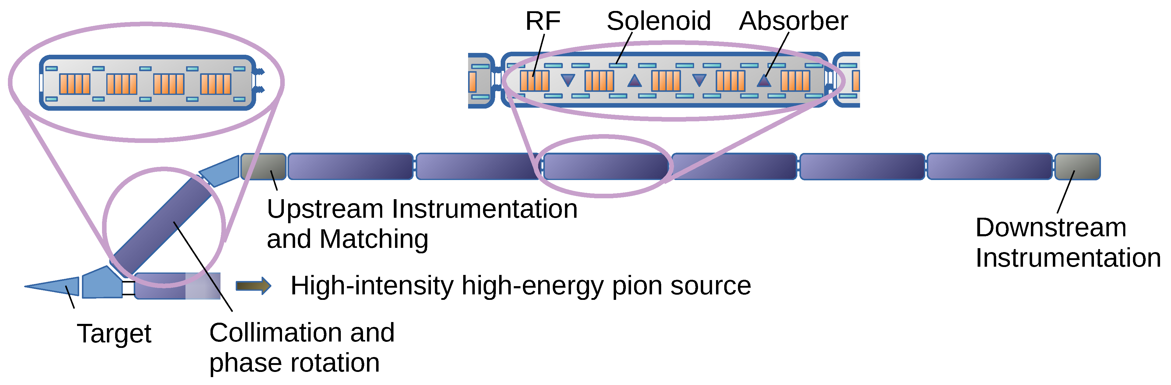
An overall schematic of the facility is shown in Figure 1. Protons are passed onto a target. An initial dipole selects muons in a momentum range between around 190 and 210 MeV/c.
The resultant beam is prepared in a series of RF cavities, which rotate the beam in phase–energy space. Collimators remove the high emittance muons at the edge of the beam. A further dipole and a collimator remove muons that do not have the correct energy, resulting in a beam that has the relatively low emittance and short bunch structure required for the Demonstrator.
The beam is passed through a short section of a uniform field, where the beam is characterised. Matching dipoles and solenoids are used to match the beam to the cooling beam line. The cooling line itself comprises a number of dipoles, solenoids, RF cavities, and absorbers. A further characterisation of the beam is performed following the ionisation cooling line.
3. Beam Preparation
The muon beam for the Demonstrator is likely to be produced by firing protons onto a horn-type target. A beam produced in such a way occupies a large volume in phase space. For the Demonstrator, it is not practicable to build a full cooling system. In order to create the rather low emittance beams required as the input to the Demonstrator, it is necessary to collimate the resultant muon beam in the beam-preparation system.
The beam-preparation system comprises a dipole to select a narrow momentum bite from the initial beam followed by a number of 0.5 T solenoids, which provide transverse focusing. The relatively low solenoid field enables collimation to the low emittances required for the cooling demonstration. High-gradient RF cavities rotate the beam in the phase–energy space. Momentum collimation is performed by a further 45 dipole. Overall, a beam having low emittance in short bunches is produced.
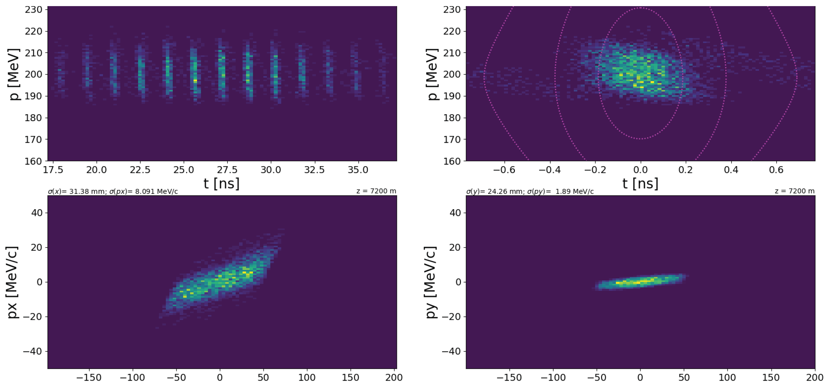
The resultant beam following the beam-preparation system is shown in Figure 2, simulated in G4Beamline [5]. A short proton bunch, only a few ns long, was assumed as the input to the target. Such a bunch can be achieved, for example, in the CERN PS or SPS. The parameters of the beam preparation system are listed in Table 1.
4. Cooling
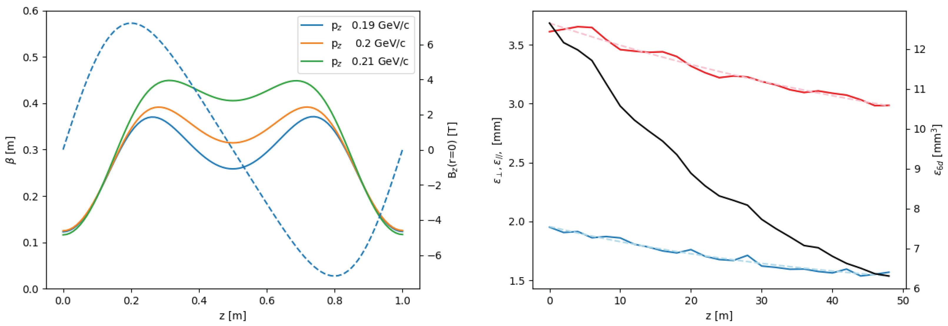
The muon-cooling system comprises a sequence of high-field solenoids to yield a tight focus at the absorber, with additional dipole coils on each solenoid to deliver sufficient dispersion. The magnetic field, optical functions and cooling performance are shown in Figure 3. Adjacent solenoids have the opposite polarity, so that the absorbers are at a focus of the lattice. Significant dispersion is excited when dipole polarity is swapped in every other dipole. While is periodic between two adjacent absorbers, the dispersion flips on each absorber, so the overall cell length is 2 m, which is the distance between three consecutive absorbers.
The optical at each absorber is roughly 0.13 m at the central momentum of 0.2 GeV/c. The phase advance in each 2 m cell ranges between at 226 MeV/c and at 145 MeV/c. The stop band at 167 MeV/c is suppressed by the symmetry of the cell and further damped by the cooling apparatus, but tolerance studies should be performed to verify that it does not become detrimental to the cell performance in the event of field errors and misalignments. The dispersion at the absorber is 63 mm, which is sufficient to induce significant longitudinal emittance reduction, even with a modest wedge angle of 5.
Overall, the cooling lattice achieves a 98% transmission over a 48 m distance, neglecting decays and assuming perfect matching. Decays would reduce the transmission by a further 4%. The transverse emittance is reduced from 1.95 mm to 1.57 mm, and the longitudinal emittance, calculated in the -energy space, is reduced from 3.61 mm to 2.99 mm. The 6D emittance is reduced from 12.7 mm to 6.3 mm, more than a factor of two reduction in emittance.
5. Practical Implementation
The facility requires access to a suitable proton beam. Two sites have been identified at CERN, and discussions are ongoing with other laboratories. It may be particularly beneficial to share the proton transfer line and target area with an experiment such as nuSTORM [6]. nuSTORM in turn would be the first demonstration of the storage of a muon beam at high energy and with muon flux approaching that required for the Muon Collider.
The integration of magnetic, RF, and absorber hardware is a subject of study. The solenoid field is rather moderate compared to existing magnets, but consideration must be made for a suitable integration of RF equipment, which may require large apertures. The overlapping solenoid and RF fields can induce breakdown in the cavities; past experiments have demonstrated configurations that mitigate this effect, but the construction of production cavities and testing in the designed solenoid field are required. Space for bellows and beam instrumentation must also be considered and is challenging to fit in such a compact lattice.
Further optimisation of the lattice is under consideration. Tighter focusing and more cooling is possible, potentially at the cost of a smaller dynamic aperture and some losses.
Funding
This work was funded by UK Research and Innovation (UKRI) under the UK government’s Horizon Europe funding guarantee (grant number 10052072) as part of Horizon Europe (HORIZON-INFRA-2022-DEV-01) under grant agreement number (101094300).
Institutional Review Board Statement
Not applicable.
Informed Consent Statement
Not applicable.
Data Availability Statement
No new data were created or analyzed in this study. Data sharing is not applicable to this article.
Conflicts of Interest
The authors declare no conflict of interest. The funders had no role in the design of the study; in the collection, analyses, or interpretation of data; in the writing of the manuscript, or in the decision to publish the results.
References
- Long, K.R.; Lucchesi, D.; Palmer, M.A.; Pastrone, N.; Schulte, D.; Shiltsev, V. Muon colliders to expand frontiers of particle physics. Nat. Phys. 2021, 17, 289–292. [Google Scholar] [CrossRef]
- Stratakis, D.; Palmer, R.B. Rectilinear six-dimensional ionization cooling channel for a muon collider: A theoretical and numerical study. Phys. Rev. Spec.-Top.-Accel. Beams 2015, 18, 031003. [Google Scholar] [CrossRef] [Green Version]
- Neuffer, D. Principles and application of muon cooling. In Proceedings of the Third LAMPF II Workshop: Los Alamos National Laboratory, Los Alamos, NM, USA, 18–28 July 1983. [Google Scholar]
- MICE Collaboration. Demonstration of cooling by the Muon Ionization Cooling Experiment. Nature 2020, 578, 53–59. [Google Scholar] [CrossRef] [PubMed] [Green Version]
- Roberts, T.J.; Beard, K.B.; Ahmed, S.; Huang, D.; Kaplan, D.M. G4Beamline particle tracking in matter-dominated beam lines. Proc. EPAC 2008, 8, 2776–2779. [Google Scholar]
- Adey, D.; Bayes, R.; Bross, A.D.; Snopok, P. nuSTORM and a Path to a Muon Collider. Annu. Rev. Nucl. Part. Sci. 2015, 65, 145–175. [Google Scholar] [CrossRef]
Figure 1.
Conceptual design of the Demonstrator for Muon Cooling.

Figure 2.
The beam following collimation. (Top left) Longitudinal phase space of all buckets; (top right) longitudinal phase space of a single bucket; (bottom left) horizontal phase space; (bottom right) vertical phase space.
Figure 2.
The beam following collimation. (Top left) Longitudinal phase space of all buckets; (top right) longitudinal phase space of a single bucket; (bottom left) horizontal phase space; (bottom right) vertical phase space.

Figure 3.
(Left) Transverse beam optics of the system for different momenta. The on-axis solenoid field is shown as a dashed line. (Right) Simulated emittance change generated by the system: (red) longitudinal emittance; (blue) transverse emittance; (black) 6d emittance.
Figure 3.
(Left) Transverse beam optics of the system for different momenta. The on-axis solenoid field is shown as a dashed line. (Right) Simulated emittance change generated by the system: (red) longitudinal emittance; (blue) transverse emittance; (black) 6d emittance.


Table 1.
Hardware parameters for the Demonstrator.
| Beam-Preparation System | |
|---|---|
| Parameter | Value |
| Cell length | 1 m |
| Peak solenoid field on-axis | 0.5 T |
| Collimator radius | 0.05 m |
| Dipole field | 0.67 T |
| Dipole length | 1.04 m |
| RF real estate gradient | 7.5 MV/m |
| RF nominal phase | 0 (bunching) |
| RF frequency | 704 MHz |
| Cooling System | |
| Parameter | Value |
| Cell length | 2 m |
| Peak solenoid field on-axis | 7.2 T |
| Dipole field | 0.2 T |
| Dipole length | 0.1 m |
| RF real estate gradient | 22 MV/m |
| RF nominal phase | 20 |
| RF frequency | 704 MHz |
| Wedge thickness on-axis | 0.0342 m |
| Wedge apex angle | 5 |
| Wedge material | LiH |
Disclaimer/Publisher’s Note: The statements, opinions and data contained in all publications are solely those of the individual author(s) and contributor(s) and not of MDPI and/or the editor(s). MDPI and/or the editor(s) disclaim responsibility for any injury to people or property resulting from any ideas, methods, instructions or products referred to in the content. |
© 2023 by the author. Licensee MDPI, Basel, Switzerland. This article is an open access article distributed under the terms and conditions of the Creative Commons Attribution (CC BY) license (https://creativecommons.org/licenses/by/4.0/).
Share and Cite
MDPI and ACS Style
Rogers, C. A Demonstrator for Muon Ionisation Cooling. Phys. Sci. Forum 2023, 8, 37. https://doi.org/10.3390/psf2023008037
AMA Style
Rogers C. A Demonstrator for Muon Ionisation Cooling. Physical Sciences Forum. 2023; 8(1):37. https://doi.org/10.3390/psf2023008037
Chicago/Turabian StyleRogers, Chris. 2023. "A Demonstrator for Muon Ionisation Cooling" Physical Sciences Forum 8, no. 1: 37. https://doi.org/10.3390/psf2023008037