Proceeding Paper

ESS Linac Overall Status and Normal-Conducting Linac Commissioning †

European Spallation Source ERIC, P.O. Box 176, SE-221 00 Lund, Sweden
*
Author to whom correspondence should be addressed.
Presented at the 23rd International Workshop on Neutrinos from Accelerators, Salt Lake City, UT, USA, 30–31 July 2022.
Phys. Sci. Forum 2023, 8(1), 36; https://doi.org/10.3390/psf2023008036
Published: 9 August 2023

Abstract

:
The European Spallation Source (ESS), currently under construction in Lund, Sweden, will be the brightest spallation neutron source in the world, when its driving superconducting proton linac achieves the design power of 5 MW at 2 GeV. Such a high-power linac requires production, efficient acceleration, and almost no-loss transport of a high-current beam (62.5 mA), thus making its design and beam commissioning challenging. Beam commissioning for the normal-conducting part of the linac is ongoing in stages. In 2022, the beam was accelerated up to the first tank of the five-tank drift-tube linac. This presentation provides a summary of the ESS linac project and presents highlights from ongoing beam commissioning.
Keywords:
ESS; commissioning; RFQ; DTL

1. Introduction

The European Spallation Source (ESS) [1], under construction in Lund, Sweden, will be a neutron source driven by a superconducting (SC) proton linac with a design beam power of 5 MW. When the beam power exceeds 2 MW, the ESS will be the brightest neutron source in the world. The linac starts with a normal-conducting (NC) injector, consisting of an ion source (IS), low-energy beam transport (LEBT), radio-frequency quadrupole (RFQ), medium-energy beam transport (MEBT), and drift-tube linac (DTL) with five tanks. The SC part has three types of cavities (Figure 1), followed by another beam transport with a dogleg at the end. The final part of the linac is the accelerator-to-target (A2T) section, where the beam is painted over a rotating tungsten target with a rastering system. Below the target, there is a tuning dump with a 12.5 kW limit. Table 1 lists high-level parameters of the linac for the design and initial operations (Ops) [1,2].
The ESS linac project is making steady progress [2,3] towards the most important milestones of sending the beam to the target and starting initial user operations. Currently, the accelerator tunnel is separated by a temporary shield wall at the foreseen location of the fifth DTL tank (DTL5) to allow activities such as high-power conditioning of cavities and beam commissioning on the NC side, in parallel to installation and testing on the SC side. Commissioning of the ESS linac is being conducted in steps (Table 2) and, as of writing this paper, the step up to DTL1 was just completed. This paper presents highlights from the commissioning steps in 2021 and 2022, where the nominal current beam was successfully sent through the RFQ to the end of DTL1.

2. Materials and Methods

This section gives short descriptions of the ESS linac up to DTL1 [1] as well as constraints and strategy for its beam commissioning [3].

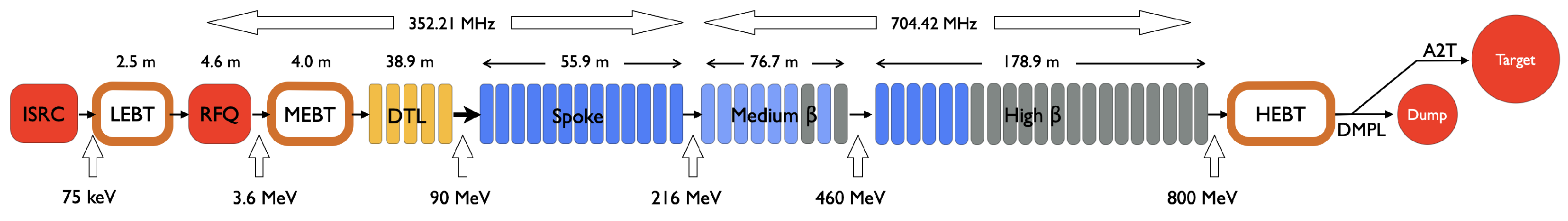
2.1. NC Linac Structures

The IS of ESS is the microwave discharge type and produces a 75 keV proton beam. The following LEBT has two focusing solenoids equipped with coils for dipole correctors. As seen in Table 2, the IS and LEBT already went through commissioning on the ESS site [4]. After the LEBT, four-vane RFQ accelerates the proton beam to 3.62 MeV and forms the bunch structure of 352.21 MHz. The subsequent MEBT includes 3 buncher cavities, 11 quadrupoles (equipped with coils for dipole correctors), and diagnostics devices. The DTL1 with 61 acceleration gaps accelerates the beam from 3.62 MeV to 21 MeV. Every other drift tube houses a permanent magnet quadrupole (PMQ), forming the FODO lattice. Dipole correctors and beam position and phase monitors (BPMs) are also housed in the drift tubes without the PMQ.
The beam pulse out of the IS is longer (∼6 ms) than the nominal 2.86 ms because of the stabilization time in the beginning. Adjustments of the pulse length and cleaning of the edges are done with the slow and fast choppers, housed in the LEBT and MEBT, respectively. Current adjustment is performed with the IS itself and the iris in the LEBT.

2.2. Constraints and Strategy

The ESS linac project has had an aggressive schedule since the beginning, which lead to the decision not to use any temporary test bench or beam dump except for the commissioning step for the IS and LEBT but instead include a comprehensive suite of permanent diagnostics in the linac [5]. During the commissioning step up to the MEBT and DTL1, the beam was sent to Faraday cups (FCs) located towards the end of the MEBT and ∼1 m downstream of the DTL1, respectively. With no dedicated beam dump, for the nominal current beam, the pulse length and repetition rate were limited to 20 μ s and 1 Hz and 5 μ s and 1 Hz, respectively, during these two commissioning steps. The aggressive schedule combined with limited resources also led to the situation where diagnostics devices available from the beginning of these two commissioning steps were only the beam current monitors (BCMs), FCs, and BPMs. Diagnostics devices such as a wire scanner and emittance meter, housed in the MEBT, had only limited time for beam tests, mostly for testing their systems. In terms of cavities and their RF systems, the buncher cavities were not available during the whole period of the commissioning to MEBT since their RF systems were not deployed yet at that point. The feedback and adaptive feed-forward of the low-level RF (LLRF) systems were still under testing phases for all the cavities.
Because of the above-mentioned situations, for these two steps up to the MEBT and DTL1, the priority was set to establish a stable beam with very low power (typically ≤6 mA, 5 μ s , and 1 Hz) and verify functionalities of available systems, especially those critical for machine safety such as the BCMs, slow chopper, and machine protection systems. Afterward, the current ramp-up was cautiously attempted. Due to the space limitation, the next section provides the overall highlights from these two commissioning steps and two selected examples of beam characterizations based on transmission measurements.

3. Results

3.1. Highlights

Within the originally allocated five weeks in 2021 for the commissioning up to the MEBT, the beam was successfully accelerated with the RFQ, and a stable beam with 6 mA, 50 μ s , and 1 Hz was established up to the FC in the MEBT. The RFQ’s output energy was verified to be ∼3.6 MeV with time-of-flight measurements. In 2022, two additional commissioning periods (nine weeks in total) were arranged, and a stable beam with the nominal 62.5 mA current and 20 μ s was established, with an excellent RFQ transmission of ∼95%. The main parameters adjusted for the high-current transmission were the solenoids and dipole correctors in the LEBT. Testing of the closed-loop operation of the RFQ also made good progress during this period, and the RFQ ran with both the feedback and adaptive feed-forward during the following commissioning step up to the DTL1.
In the following commissioning step up to the DTL1, it took only a few days to establish a stable low power beam (∼6 mA, 5 μ s , and 1 Hz) to the end of the DTL1. This was because most of the critical systems for machine safety were already verified during the preceding step. Transport of the nominal 62.5 mA current beam was first attempted on 1st July 2022 and established within a few hours.
Further details of these two commissioning steps can be found in [6].

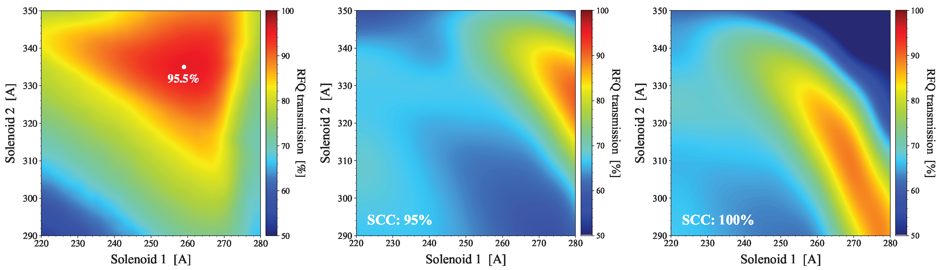
3.2. Matching to RFQ

One of the most important transverse tunings for a hadron linac is the matching to the RFQ. The common method for a LEBT with two solenoids is to scan them and find the combination which maximizes the transmission through the RFQ. This is because the condition maximizing the transmission is also the best for beam quality, e.g., minimizing emittance growth [7]. Figure 2 compares a measurement (left) and simulations (middle and right). The best transmission measured was 95.5%, which was very close to the model prediction of 97–98%. On the other hand, differences are seen in the position of the optimal point and the overall pattern. It is also seen that the simulation result is sensitive to the level of space-charge compensation (SCC). These results are still preliminary; additional measurements will be performed in the future and simulation studies will continue.

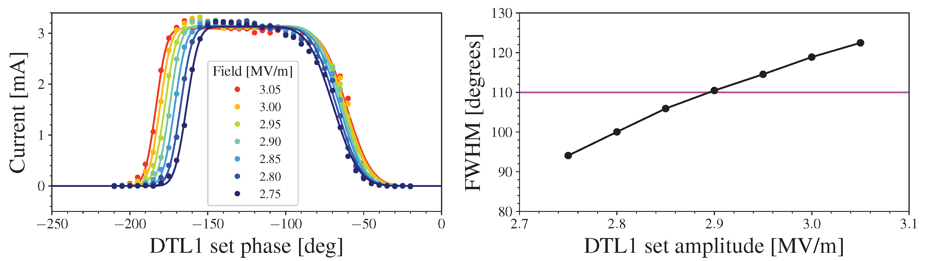
3.3. DTL1 Transmission Scan

The most significant tuning for a hadron linac is to set the RF amplitudes and phases of all the cavities one by one from the downstream, thus establishing synchronizations among cavities. This is typically done by scanning the phase of the cavity under tuning for different levels of amplitudes and, at the same time, measuring the phase changes in downstream locations. Results for this type of cavity tuning are summarized in [8].
For the DTL1, the amplitude and phase can also be set with a transmission scan. Figure 3-left shows the output current for a low ∼6 mA case, measured with a BCM, scanned over the set phase for different levels of amplitudes. As seen in the figure, the width of the finite transmission region depends on the amplitude. Figure 3-right shows the relation between the FWHM of the finite transmission region and the set amplitude. The model predicts 110 degrees for the design amplitude of 3.05 MV/m, which occurred at the set field of ∼2.9 MV/m, indicating the set field based on the RF measurement being off by −5%.

4. Discussion

Because of the limited availability of diagnostics, model verification has been performed mostly against the measured transmission so far. In the future commissioning steps, when the devices such as the wire scanner and emittance meter become available, more detailed characterizations and model comparisons for this part of the linac will be repeated.

5. Conclusions

The ESS linac project is making progress toward the initial operation at 800 MeV and 2 MW. During commissioning in 2021 and 2022, the nominal 62.5 mA current beam was successfully sent through the RFQ to the end of DTL1. Due to the limited availability of diagnostics devices, more detailed characterizations and model comparisons of this part of the machine will be repeated during future commissioning steps.

Author Contributions

Methodology, M.E. and R.M.; formal analysis, Y.L., N.M. and D.N.; data curation, Y.L., N.M. and D.N.; writing—original draft preparation, R.M.; writing—review and editing, M.E., Y.L., N.M. and D.N.; All authors have read and agreed to the published version of the manuscript.

Funding

This research received no external funding.

Institutional Review Board Statement

Not applicable.

Informed Consent Statement

Not applicable.

Data Availability Statement

Not applicable.

Acknowledgments

The authors would like to thank all the ESS staff and external partners who contributed to the work for the NC part of the ESS linac.

Conflicts of Interest

The authors declare no conflict of interest.

References

  1. Garoby, R.; Vergara, A.; Danared, H.; Alonso, I.; Bargallo, E.; Cheymol, B.; Darve, C.; Eshraqi, M.; Hassanzadegan, H.; Jansson, A. The European Spallation Source Design. Phys. Scr. 2017, 93, 014001. [Google Scholar]
  2. Jansson, A. The Status of the ESS Project. In Proceedings of the 13th International Particle Accelerator Conference (IPAC’22), Bangkok, Thailand, 12–17 June 2022; pp. 792–795. [Google Scholar]
  3. Plostinar, C. Status of the Normal Conducting Linac at the European Spallation Source. In Proceedings of the 13th International Particle Accelerator Conference (IPAC’22), Bangkok, Thailand, 12–17 June 2022; pp. 2019–2022. [Google Scholar]
  4. Miyamoto, R.; Bebb, R.E.; Bergman, E.C.; Bertrand, B.; Danared, H.; Derrez, C.S.; Donegani, E.M.; Eshraqi, M.; Müller, J.F.E.; Fay, T.; et al. First Results of Beam Commissioning on the ESS Site for the Ion Source and Low Energy Beam Transport. In Proceedings of the 10th International Particle Accelerator Conference (IPAC’19), Melbourne, Australia, 19–24 May 2019; pp. 1118–1121. [Google Scholar]
  5. Shea, T.; Baron, R.; Cheymol, B.; Derrez, C.; Grandsaert, T.; Jansson, A.; Hassanzadegan, H.; Dolenc-Kittelmann, I.; Kocevor, H.; Molloy, S.; et al. Overview and Status of Diagnostics for the ESS Project. In Proceedings of the 6th International Beam Instrumentation Conference (IBIC’17), Grand Rapids, MI, USA, 20–24 August 2017; pp. 8–15. [Google Scholar]
  6. Miyamoto, R.; Amstutz, C.; Armanet, S.; Baron, R.; Bergman, E.; Bhattacharyya, A.; Bolling, B.; Borg, W.; Calic, S.; Carroll, M.; et al. Beam Commissioning of Normal Conducting Part and Status of ESS Project. In Proceedings of the 31st International Linear Accelerator Conference (LINAC’22), Liverpool, UK, 28 August–2 September 2022; pp. 18–24. [Google Scholar]
  7. Miyamoto, R.; Eshraqi, M.; Jansson, A.; Laface, E.; Levinsen, Y.; Milas, N.; Munoz, M.; Ponton, A.; Sargsyan, E.; Tchelidze, L.; et al. Preparation Towards the Ess Linac Ion Source and Lebt Beam Commissioning on Ess Site. In Proceedings of the 9th International Particle Accelerator Conference (IPAC’18), Vancouver, BC, Canada, 29 April–4 May 2018; pp. 874–877. [Google Scholar]
  8. Levinsen, Y.; Akhyani, M.; Baron, R.; Donegani, E.; Eshraqi, M.; Sosa, A.G.; Hassanzadegan, H.; Jones, B.; Milas, N.; Miyamoto, R.; et al. First RF Phase Scans in the European Spallation Source. In Proceedings of the 11th International Beam Instrumentation Conference (IBIC’22), Kraków, Poland, 11–15 September 2022; pp. 313–317. [Google Scholar]
Figure 1. ESS linac schematic layout during the initial 2 MW Ops. The segments in the DTL and SC sections denote DTL tanks or cryomodules. The cryomodules in gray will not be powered during the initial Ops, making the beam energy and power 800 MeV and 2 MW for each.
Psf 08 00036 g001
Figure 2. RFQ transmission vs. LEBT solenoids. Left: Measurement. Middle: simulations with a 95% SCC. Right: Simulation with 100% SCC.
Psf 08 00036 g002
Figure 3. Left: DTL1 transmission vs. phase. Right: FWHM vs. amplitude. The model predicts a 110 degrees FWHM for the design 3.05 MV/m amplitude, indicating the set field being off by −5%.
Psf 08 00036 g003
Table 1. ESS linac high-level beam parameters for the design and initial Ops.
ParameterUnitDesignInitial Ops
PowerMW52
Kinetic energyGeV20.8
Peak currentmA62.562.5
Pulse lengthms2.862.86
Repetition rateHz1414
Duty factor%44
Table 2. ESS linac commissioning steps.
StepStartEnergy [MeV]
Commissioning to LEBT2018-090.075
Commissioning to MEBT2021-113.62
Commissioning to DTL12022-0521
Commissioning to DTL4202374
Commissioning to Dump2024570
Commissioning to Target2025570
Start of user operations2026800
Disclaimer/Publisher’s Note: The statements, opinions and data contained in all publications are solely those of the individual author(s) and contributor(s) and not of MDPI and/or the editor(s). MDPI and/or the editor(s) disclaim responsibility for any injury to people or property resulting from any ideas, methods, instructions or products referred to in the content.

