Article

The Impact of Roof Material Profile and Pigmentation on the Performance of Photovoltaic Modules

1
Department of Energy, Gas and Petroleum Engineering, Kenyatta University, P.O. Box 43844, Nairobi 00100, Kenya
2
Department of Physics, Kenyatta University, P.O. Box 43844, Nairobi 00100, Kenya
*
Author to whom correspondence should be addressed.
Solar 2023, 3(4), 618-637; https://doi.org/10.3390/solar3040033
Submission received: 21 September 2023 / Revised: 25 October 2023 / Accepted: 26 October 2023 / Published: 1 November 2023

Abstract

:
This study combines simulations and experiments to study the heat interactions between various types of roofs and the photovoltaic (PV) modules installed on them. Specifically, the performance of PV modules on a clay roof was compared with their performance on two types of metal roofs, a Box-profile metal roof and an Orientile metal roof, which differ in shape and geometry. Additionally, this study examined the cooling potential of three common metal roof pigments, iron (iii) oxide (Fe2O3), titanium dioxide (TiO2) and basalt, on roof-installed PV modules. An unpigmented roof was also studied for comparison purposes. Model development and simulation were implemented in COMSOL Multiphysics, and the simulation results were validated and compared with field experiments. The maximum open-circuit voltages of the PV installations were found to be 21.096 V for the clay roof, 20.945 V for the Box-profile metal roof and 20.718 V for the Orientile metal roof. This study revealed that the unpigmented roof had higher solar cell temperatures compared to the pigmented models, with temperature gains ranging from 2.2 °C to 2.71 °C. Moreover, the unpigmented model displayed significantly higher surface radiosity than the pigmented models. The performance output of the modules also varied depending on the metal roof sheet shape and geometry, with the Box-profile metal roof yielding better results than the Orientile metal roof sheet. These results indicate that a specific roof pigmentation may have a small impact on a single PV module, but it can become significant in a large array of modules, especially if cooling through natural convection is hindered.

1. Introduction

Metal roofs have been the most popular roof types in developing countries in Africa [1]. Some advantages of metal roofs, amongst others, are their longevity [2], numerous varieties and easy installation/compatibility with solar panels. However, there are key challenges associated with metal roofs. Apart from the fact that they are prone to corrosion, as well as causing noise when it rains, they also heat up a lot faster when compared to other roof types [3]. Environmental factors such as wind speed and direction play key roles in the heat transfer capability of a roof [4]. The shape of a roof material can affect its rate of wind cooling; therefore, the case of roof geometry/shape impacting the overall heat build-up of the roof can be made [5]. In sub-Saharan Africa, there are two very common metal roofs that are notably distinct in their geometry, although they are manufactured from similar materials of iron. These are the Orientile metal roof and the Box-profile metal roof, presented in Figure 1. These roofs are particularly common because of their durability and cost-effectiveness.
The geometry of a roof has a definite influence on the thermal behavior of the roof material [6] and the energy balance of a building envelope. Experimental research, as well as numerical studies [7,8], conclude that roof shape and geometry influence roof cooling performance. Although roof geometry/shape does not lead to changes in the properties of the base material, they influence the ambient heat interactions of the roof, which can influence the temperature of the roof surface. However, the question of whether roof geometry and design are significant enough to consequentially affect the performance of an installed solar PV module remains.
Clay tile roofs are gradually becoming a common roof choice for upmarket households in tropical climates due to their resistance to temperature fluctuations [9], as well as their ability to reduce the temperature of a building envelope [10]. The roofing underlay in clay tile roofs provides extra ventilation [11], allowing for convective heat transfer. This provides the material with extra cooling features and makes it desirable in hot-climate regions [12]. While clay tile roof materials have been manufactured using various novel techniques to improve their cooling features [13,14], the tile roof material has been documented to be a cool roof material even in its natural albedo [15]. Clay tile solar PV installations are a good performance benchmark for metal roof solar PV installations because they give superior PV outputs [16]. The roofs are generally cooler and thus radiate lower heat to the back of solar panels.
To combat the problem of temperature build-up in metal roofs, the use of roof reflective coatings is becoming popular. Acrylic, silicone and polyurethane coatings are known to reduce thermal discomfort in buildings, which makes them among the most widely used roof coatings [17]. However, these coatings are blended with pigmentations of various types, widely referred to as ‘cool pigments’, because they help reduce the building’s air conditioning energy demand during hot seasons [18]. The high solar reflectance and infrared emission of certain pigments/coatings make them effective in decreasing the temperature of the building envelope [19]. Furthermore, different pigments result in different heat transfer properties, as demonstrated in the literature [20,21]. Most color-coated sheets are increasingly manufactured with pigmentations of different types and colors to give a fine matt or gloss finish. These pigments are applied for various reasons, including aesthetic design purposes, heat dissipation and/or reflection, better quality for the roofs, ease of maintenance and improved resistance of the roofing sheets. Major pigmentation types that are often used include iron (iii) oxide (Fe2O3), titanium dioxide (TiO2), basalt and sometimes charcoal. Badin et al. [22] presented the results of their study on the effects of iron oxide and titanium dioxide on the thermal characteristics and performance of asphalt, noting significant differences between the temperatures of pigmented samples and those of unmodified samples.
Iron oxide, in particular, comes in different blends, which may be either natural or artificially produced. However, the most notable and practical iron oxide pigments are yellow α-FeOOH, red α- Fe2O3 and black Fe3O4 [23]. Industrial processes, including the Laux process, the solid-state process and the precipitation process, are utilized to produce synthetic iron oxide pigments commercially. Interestingly, the various iron oxide pigments, though they originate from the same family, still differ in their thermal properties. Titanium dioxide pigmentation, another widely used pigmentation, has been manufactured through many novel processes but commercially manufactured through high-temperature chloride processes [24]. Basalt pigmentation, also widely utilized, has been studied extensively, and its effects on the mechanical and physical properties of roofs have been documented [25]. The size of the basalt fibers is known to affect the mechanical properties of roofs [25]. Another type of pigment is the complex inorganic color pigments (CICPs), which are structurally similar to pigments such as TiO2 and Fe2O3 but still pose unique thermal and physical properties [26]. When the temperature of a building is higher than the ambient temperature of the surroundings, the building dissipates heat through heat transfer mechanisms of conduction, convection, radiation and evaporation [27]. The rate at which this heat is dissipated is directly correlated with the surface reflectance of the building, which is greatly influenced by the roofing material color and pigmentation. The significant influence of material types on the heat dissipation of roofs, as well as on energy consumption, is well documented [28,29,30]. Pena [31] experimentally investigated how improved white acrylic paint coatings with NIR pigments composed of varied percentages of TiO2 reduced thermal discomfort in buildings, with results indicating temperature reductions as high as 7.8 °C. Lev et al. [32] demonstrated novel results of roof cooling from ZnTiO3 pigments, which produced superior results to ZnO and TiO2 with a cooling effect as high as 14.9 °C.
The choice of the roofing material geometry/shape or material pigments rarely considers any solar photovoltaic (PV) module retrofits at the design stage. PV modules tend to perform better in systems where heat dissipation is facilitated, and heat accumulation is minimal. A key indicator of the performance of PV modules is the temperature build-up and distribution on the PV cells. Alshayeb and Chang [33] utilized PV cell temperature as a performance indicator in a thermal study investigating the performance of modules installed on green and black roofs.
It has been documented that the increase in PV cell temperatures leads to voltage drops [34] and a decrease in overall power [35,36]. Karki [37] presented results that indicated that increases in PV cell temperatures directly lead to a decrease in output voltages. The importance of a unit increase in temperature was highlighted by Dwivedi et al. [38], who noted that for a 1 °C decrease in the temperature of a PV module, a 0.05% increase in efficiency was recorded. Due to the sensitivity to temperature of PV modules in roof designs, the choice of roofing materials, including their pigmentations as well as geometry/shape, become important decision-making variables.
As many households in tropical Africa increasingly look to solar PV technology as an alternative source to conventional sources of energy, the need for optimization in building architecture arises. The design of building roofs with pigmentations and the efforts sought to reduce thermal energy accumulation in the building envelope may perhaps be counter-productive when it comes to roof-top solar installations. Pigmentation cooling of a building indicates that the building loses heat, but this heat, a form of energy, cannot be destroyed but is instead transferred to another medium. Therefore, the question of where most of this lost heat is transferred arises.
The novelty of this research is to examine the potential of roof geometry/shape on the performance of roof-installed PV modules in sub-Saharan climates as well as to investigate influences of different material pigmentations on the reflective and radiative properties of roof materials and, consequently, the heat transfer interactions with roof installed PV modules. This study was limited to the investigation of a basic clay roof material and three metal roof pigments. Investigation into various novel offsets of clay roof materials was not explored. Also, investigations on whether a specific coating was best suited for a specific roof material in relation to PV performance were not carried out.

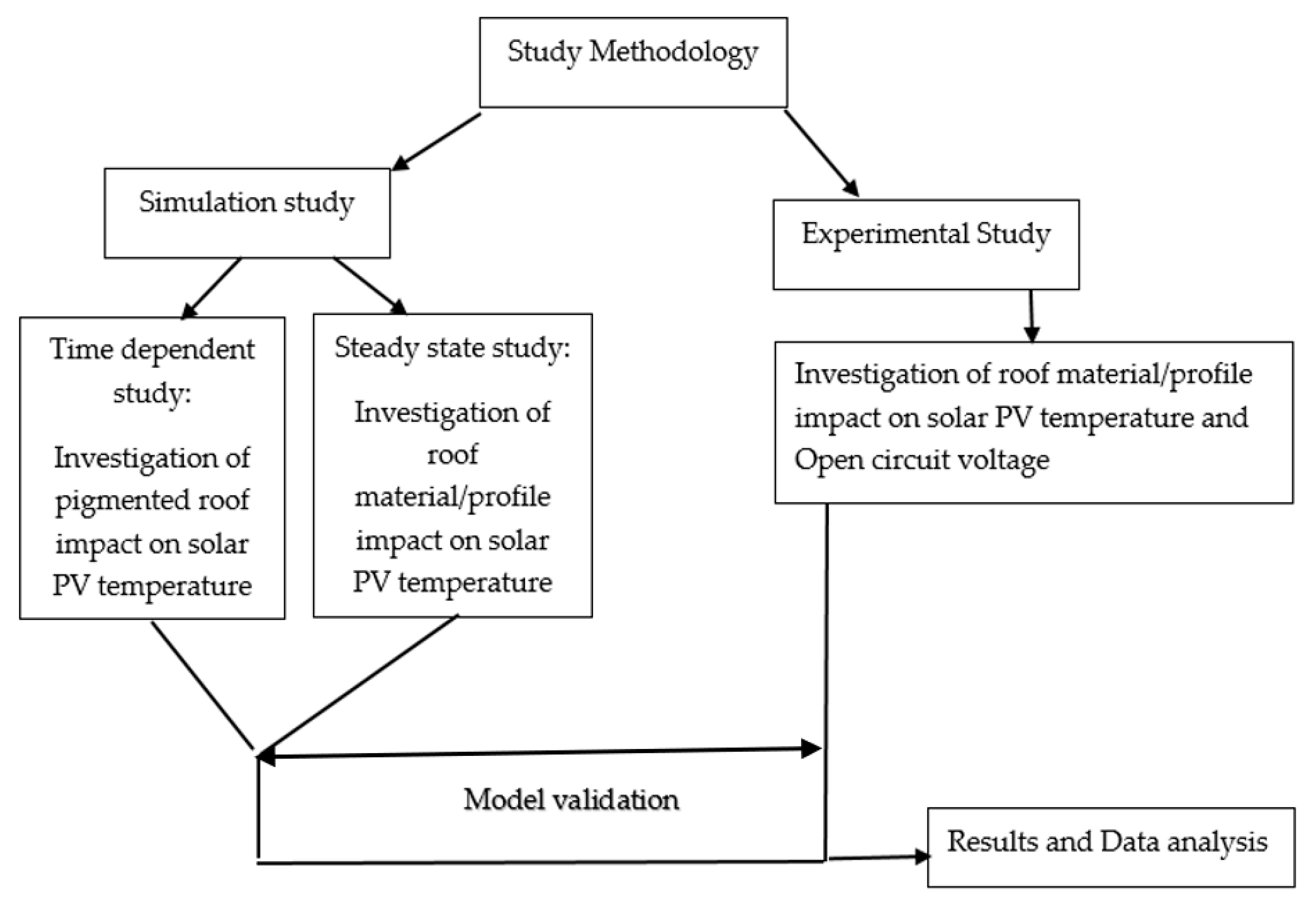
2. Solution Procedures

The methodology utilized comprises simulation as well as experimental study, as presented in Figure 2. The simulation study further investigated the role of various roof pigments on solar PV temperatures, and the results were validated and compared with experimental data. The experimental study expanded the study of temperature profiles and their effects on solar PV voltage outputs.

2.1. Governing Equations and Heat Transfer

Heat interactions between a PV module and a pigmented roofing material were investigated by implementing a time-dependent finite element analysis on a 3-D numerical model. The governing equations applied for the numerical method are conservation of mass, momentum, and energy, and they are collectively applied as the Navier–Stokes equations [39]. These equations are applied along with heat transfer mechanisms of conduction, natural convection and radiation.
The conservation of mass principle accounts for the kinematic characteristics of wind flow between the PV module and the roof, as well as the density of air. It provides insights into the in and out flow of air mass in the system.
ρ t + ρ v = 0 ,
The differential equation of the continuity/mass conservation equation presented in Equation (1) corresponds to the rate of air mass storage in a volume ( ρ t ), the air mass that enters through the boundary surfaces of the model (− ρ v ) , where v is the vector of air flow velocity, ρ is the density of air, t is time, and is the differential operator. The fluid (air) is assumed to be incompressible, indicating that the density of the fluid is constant with time.
v = 0 ,
Therefore, Equation (1) is simplified into Equation (2). The conservation of momentum applies to the model, and momentum, being a vector quantity, has direction, and the conservation principle also applies to its direction. Thus, in the absence of external forces, the direction components will also be conserved.
ρ v t + ρ v v = p + { μ v + v Ʈ } + ( λ v ) ,
The differential equation for momentum conservation is presented in Equation (3), where v is flow velocity gradient, t is time, ρ is the mass density, p is flow pressure gradient, μ is dynamic viscosity, Ʈ is the stress vector, λ refers to the bulk viscosity and is the differential operator. As described in Equation (2), for incompressible flow, . V = 0 . It is also assumed for this model that the air viscosity is constant.
ρ v t + ρ v v = p + μ 2 v ,
Therefore, the simplified version of the conservation of momentum equation presented in Equation (4) is applied. The energy conservation principle [40] is applied to the model. Thus, the heat energy transferred across the model is conserved. As in the case of this model, the temperature of the system is a key factor.
ρ C p T t + [ ρ c p v T ] = ( K     T ) + Q T ,
Therefore, the differential equation for energy conservation is presented in terms of temperature in Equation (5) where ρ is density, C p is the specific heat capacity at constant pressure, T is temperature, v is flow velocity, K represents thermal conductivity, Q is energy flux, and   is the differential operator. The heat energy transfer through layers of the PV module was represented by Fourier’s law of heat conduction, and it is presented as follows:
Q cond = Q A t = K   T = K   ( T x e x + T y e y   + T z e z ) ,
Equation (6) presents Fourier’s law, where Q is heat energy, A is surface area; t is time; K is thermal conductivity; T is temperature gradient; e x   e y   e z are directional components; and is the differential operator. The thermal conductivity K of a given material layer is assumed to be homogenous across all directions e x   e y   e z .
Qconv = hc A (TsTm),
The convective heat transfers between the roof surface and the back of PV modules are represented in Equation (7). hc is convective heat transfer coefficient, A is surface area, and Ts and Tm are roof surface temperature and PV module temperature. The equation for the radiative heat transfer mechanism for this model is as follows:
Q rad   =   σ e A T m 1 4 T m 2 4
Ambient-to-surface and surface-to-surface radiative heat transfer is represented in Equation (8), where σ is the Stefan–Boltzmann constant, e is the emissivity of surface and Tm1 and Tm2 are absolute temperatures of heat transfer mediums.

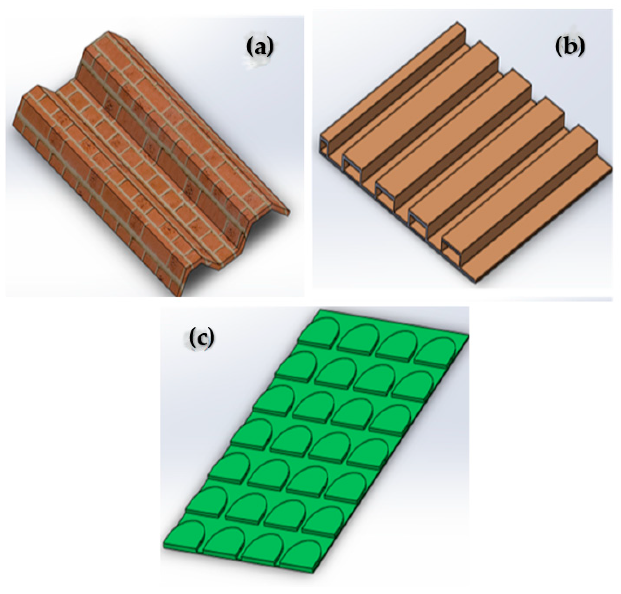
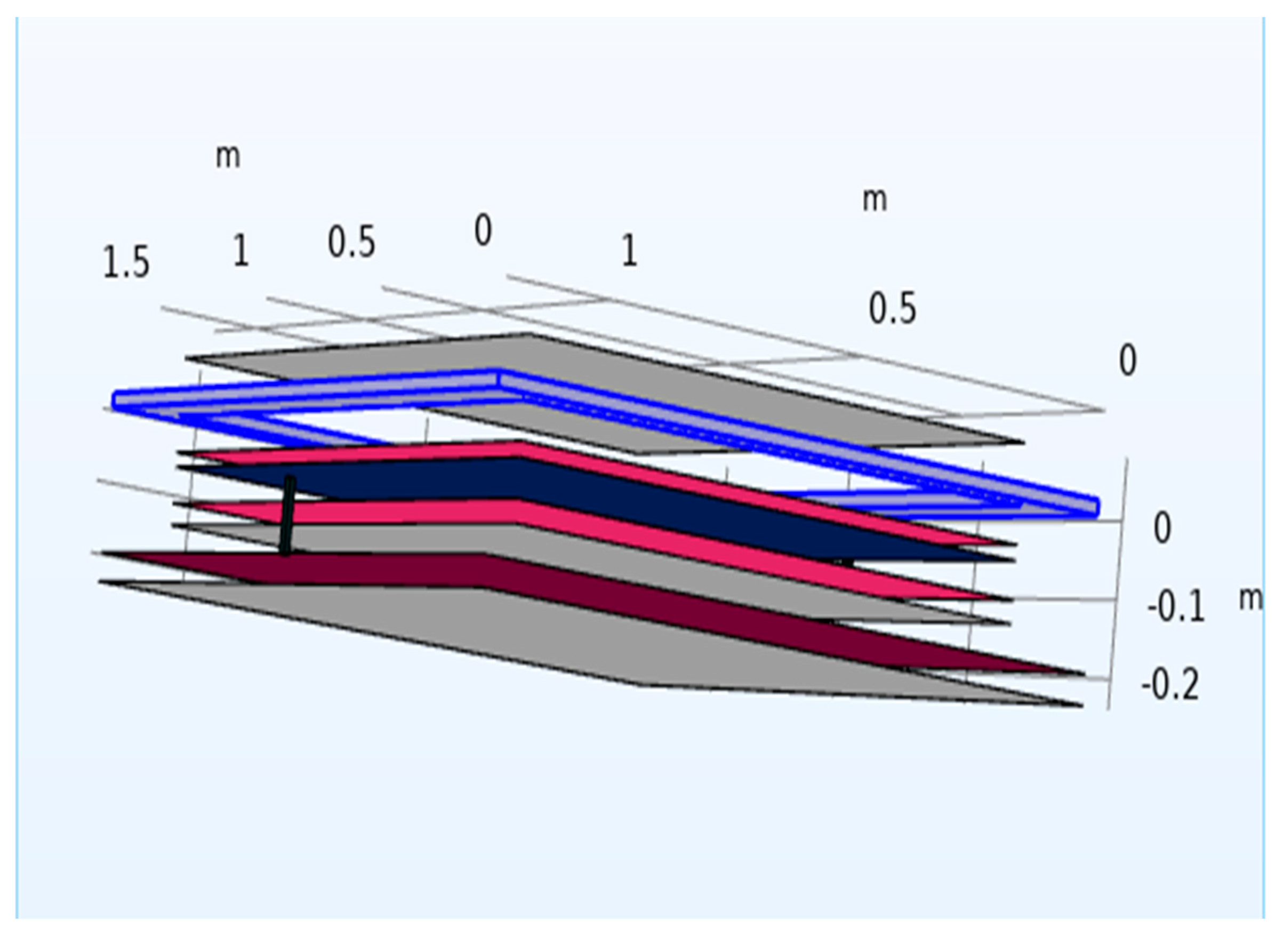
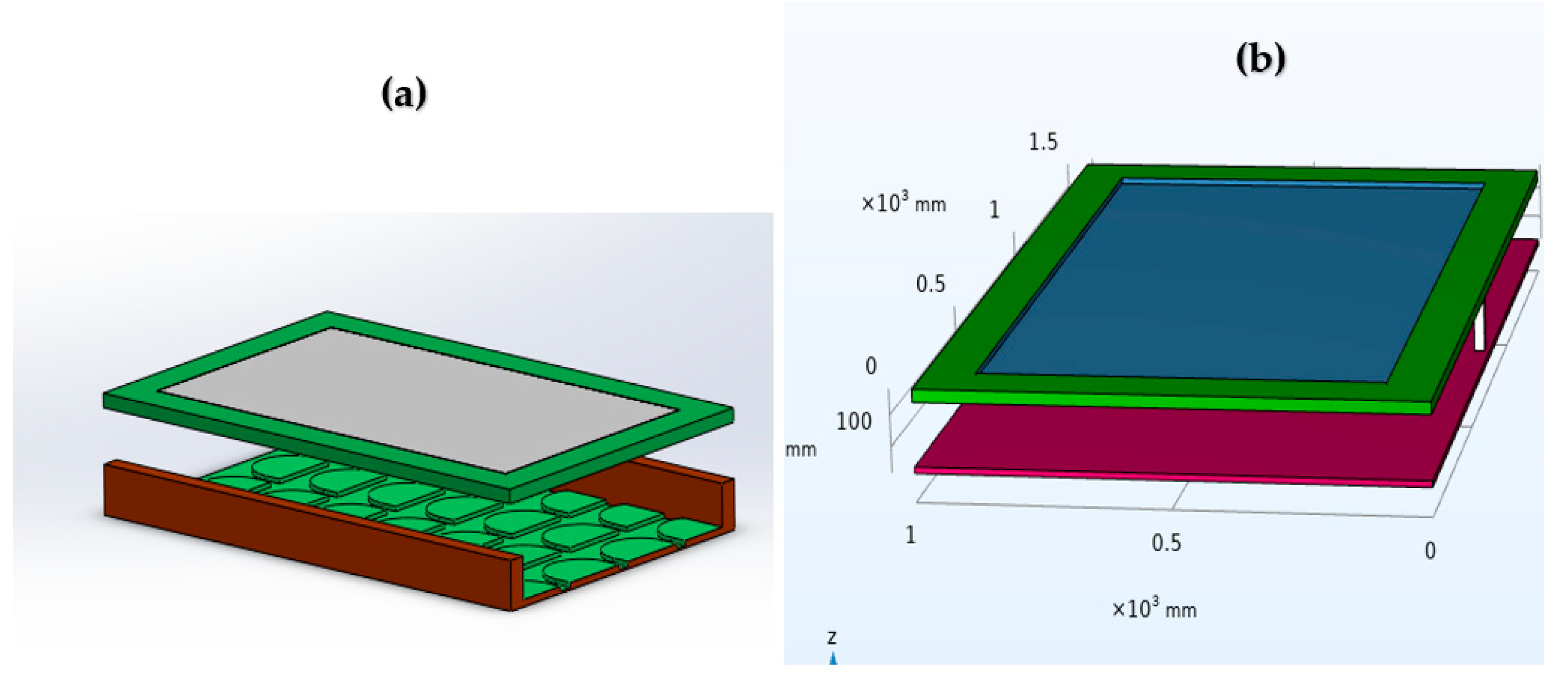
2.2. Model Development

The finite element analysis (FEA) was implemented on the 3-D models developed in COMSOL Multiphysics software version 6.1. The COMSOL software is a powerful tool for modeling heat transfer between solids with inbuilt features capable of simulating practical designs. This is a numerical method that is utilized to provide approximate solutions to practical problems. Two models are developed: (1) a model with various roof types and (2) a model with various roof pigmentations. The 3-D models comprised a PV module with layers of tempered glass, EVA, solar cell and Tedlar fitted in an aluminum frame. For the complete model build, a roof is modeled and assembled with the PV module. Figure 3 presents the three roof types, clay tile, Orientile metal roof and Box-profile metal roof, that were modeled, and Figure 4 presents the exploded view of the PV module components and roof surface with a pigmented layer. The PV module components and roof assembly presented in Figure 4 from top to bottom are tempered glass layer, aluminum frame, ethyl vinyl acetate (EVA) layer-1, solar cell, EVA layer-2, Tedlar layer, pigment layer and roof surface layer. Three different types of roof pigmentations were studied, which comprised iron oxide (Fe2O3), titanium oxide (TiO2) and basalt. The utilized thermal properties of Fe2O3 and TiO2 were documented by Badin et al. [22], and those of basalt were adopted from Bhat et al. [41]. Figure 5 shows the assembled model of one of the roof materials (Orientile metal roof (Figure 5a)) and an assembled model with the roof surface layer pigmented with one of the investigated pigments (Fe2O3 (Figure 5b)). The airgap/clearance between the roof surface and the PV module is fixed at 100 mm, and the module dimensions’ length and width are 1500 mm and 1000 mm, respectively.
As shown in Figure 5, a uniform roof clearance is maintained throughout this study so that variations in results can be attributed to the different roof geometries and properties (Figure 5a) and varying pigmentation types (Figure 5b). For uniformity across pigmented models, a simple galvanized iron roof layer is utilized. Pigmentations are treated as an extra layer on the roof surface. Table 1 shows the thermal properties of the standard materials used in the model.
The boundary conditions for the models are set with solar irradiance of 1000 W/m2 and an ambient temperature of 28 °C, and the initial temperature of the roof is set at 50 °C. A heat transfer coefficient of 17.5 W/m2C is applied to the model, and the wind speed considered in this study reflects the weather conditions in Kenya, where the average wind speed has been documented to be 3.1 m/s [42]. The boundary condition for the surface-to-surface radiation between the surface of the roof and the back sheet of the module is modeled with the defined ambient conditions and emissivity of the materials.

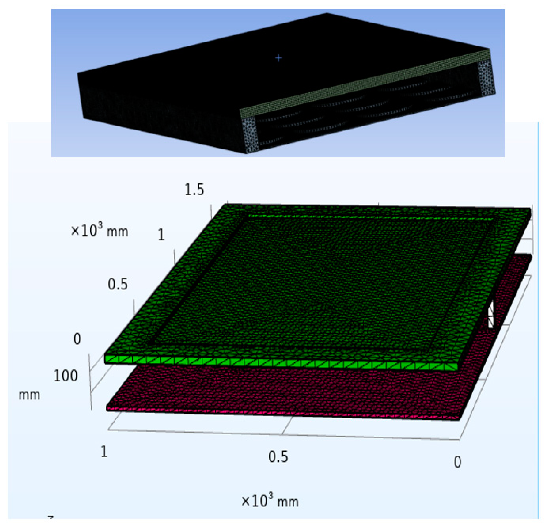
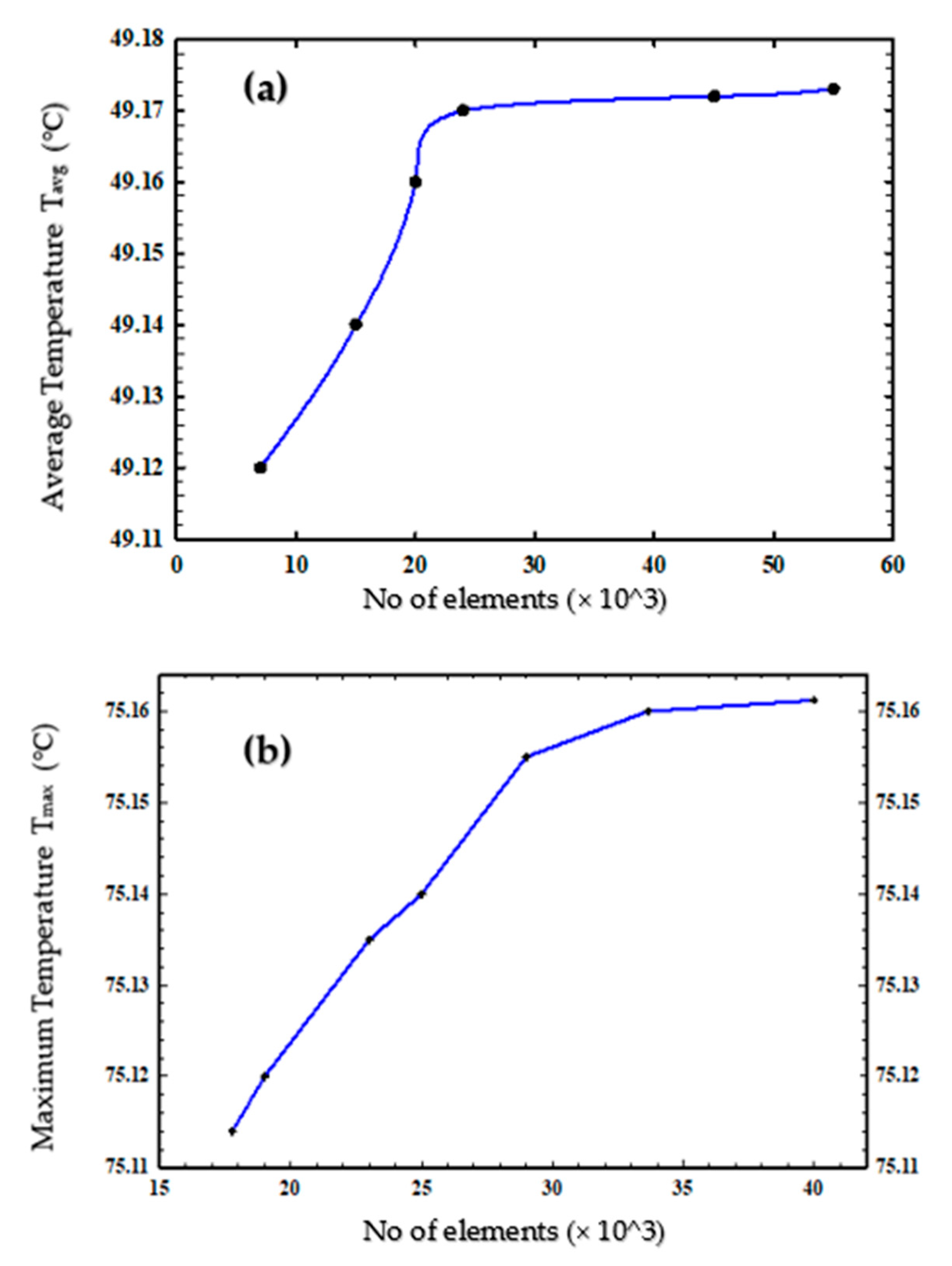
2.3. Simulation Procedures

The developed models are meshed, as shown in Figure 6, and mesh sensitivity testing was carried out on the models. This testing involved several simulations of the temperature of the PV cell surface using different numbers of meshing elements. Steady-state thermal simulations, which are time-independent simulations, were carried out on the model investigating roof types. Transient simulation was carried out on the model investigating pigmentation types. Figure 7a reveals that 24,150 meshing elements are adequate for the Orientile roof model. The meshing elements sufficient for the Box-profile roof sheet and clay tile roof models are 15,000 and 16,650, respectively. Figure 7b reveals that 33,750 elements are sufficient for accurate simulation of the pigmentation model. Cell surface temperature distribution and radiosity are studied by simulating the model heat transfer environment for 3600 s.

2.4. Model Assumptions

In the development of the model, several assumptions were made. First, two simulation environments are used: (1) steady-state thermal and (2) transient-state thermal. Air viscosity is assumed to be constant. Thermal conductivity is assumed to be homogenous in all directions. A constant mass flow rate is applied, and the fluid flow is assumed to be incompressible.

2.5. Model Validation Procedures

Simulation results were compared with experimental data to investigate trends and check for their validity. Furthermore, a sample of the simulation results was compared with the available literature on the various roof pigmentations studied to investigate their conformity with the documented thermal and heat transfer behaviors of the pigments [43].

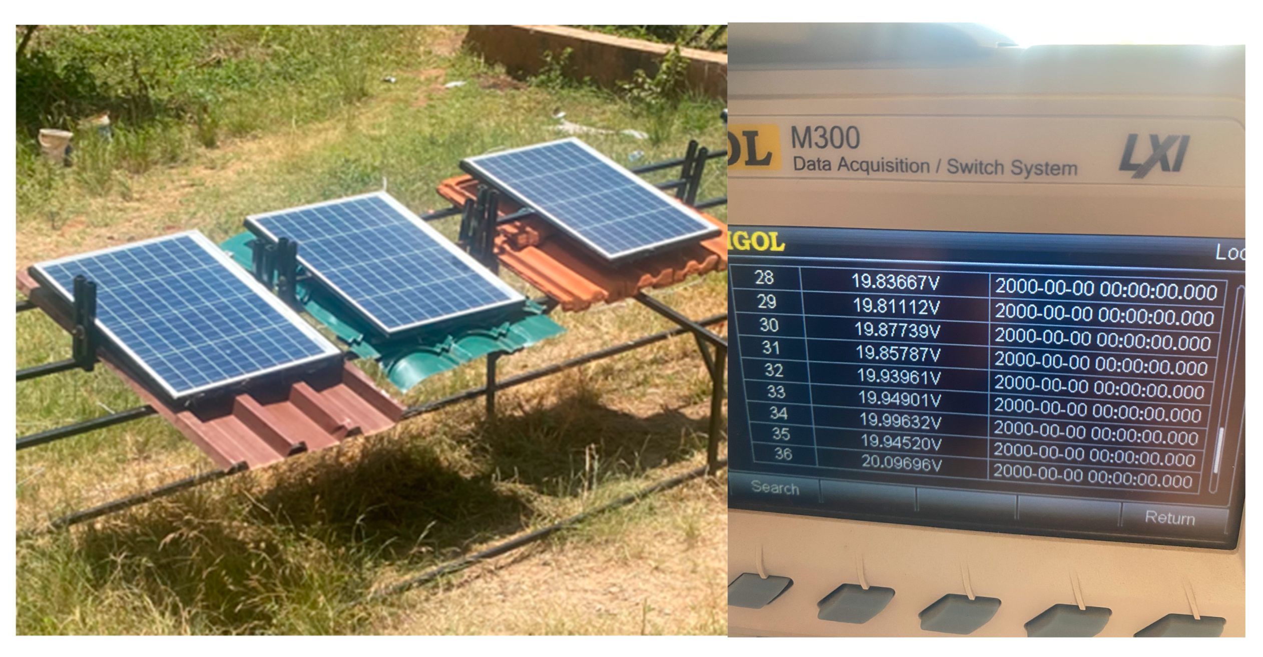
2.6. Experimental Method

To investigate the performance of PV modules on various roof profiles and materials, 50 Wp (+/−5% maximum variation) solar polycrystalline PV modules with a maximum open-circuit voltage of 21.6 V were installed on the various roofs which were affixed on a 15° inclined platform. The dimensions of the roofs were approximately 1800 mm in length and 1200 mm in width. The experiment was conducted under no load conditions, and thermocouples were attached to the back of the modules and then connected to a data logger. The terminals of the modules were also connected to the data logger using cables. The data logger was used to collect data for open-circuit voltage and PV module temperature. The setup is presented in Figure 8. The PV panels were maintained at 100 mm from the roofs, and this clearance distance was measured from the back sheet of the PV module to the crest (high edge) of the roofing material. The data were collected every 3 min for 2 h from 12.00 noon to 2.00 pm daily.

3. Results and Discussion

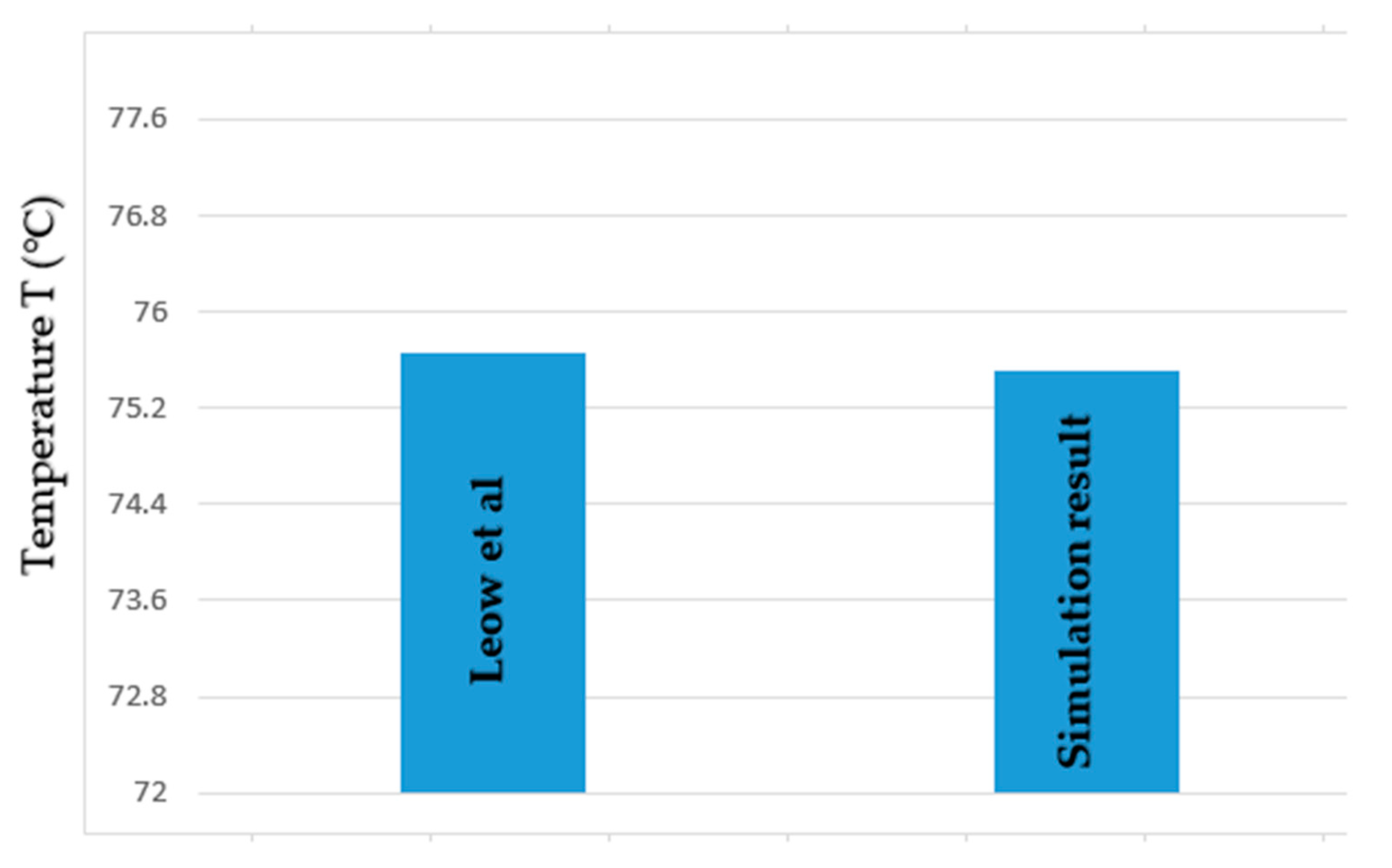
3.1. Model Validation

The temperature distributions of the PV modules on the three roof types were compared with results from experiments. Both results follow the same trend and agree that the PV module on the clay tile roof gives the lowest cell temperatures, therefore validating the model. Further, simulations reveal results similar to those of the study by Leow et al. [44] when the same parameters and conditions were imputed. Results from this study were also compared with the available literature on pigmentations. Miller and Ridge [43] utilized the ASTM D4803 test procedures [45] described by Zubielewicz et al. [26] to test for the maximum temperature of standard pigmented roofs exposed to an equal flux of 484 Btu (hr.ft2) from an infrared heat lamp. The results indicate that the roof temperature is highest in pigmented materials with relatively higher percentages of Fe2O3 compared to TiO2. Pigmented constituents with 96.8% TiO2 and 1.7% Fe2O3 recorded a maximum temperature of 94.4 °C while pigmented constitutes with 75% TiO2 and 13.2% Fe2O3 recorded a maximum temperature of 107.2 °C, a temperature difference of 12.8 °C. The model of this study also reveals a peak temperature of the solar cell assembled with the pigmented roof of Fe2O3 to be higher than the peak temperature observed on the solar cell with TiO2 assembly with a temperature difference of 0.35 °C.

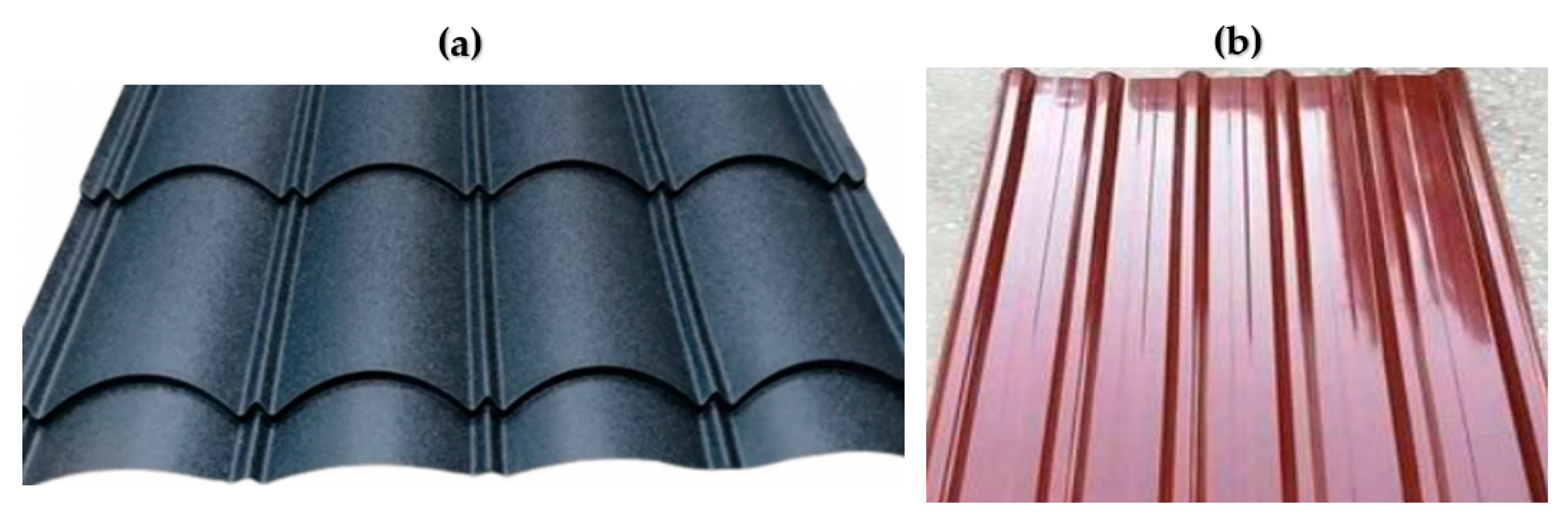
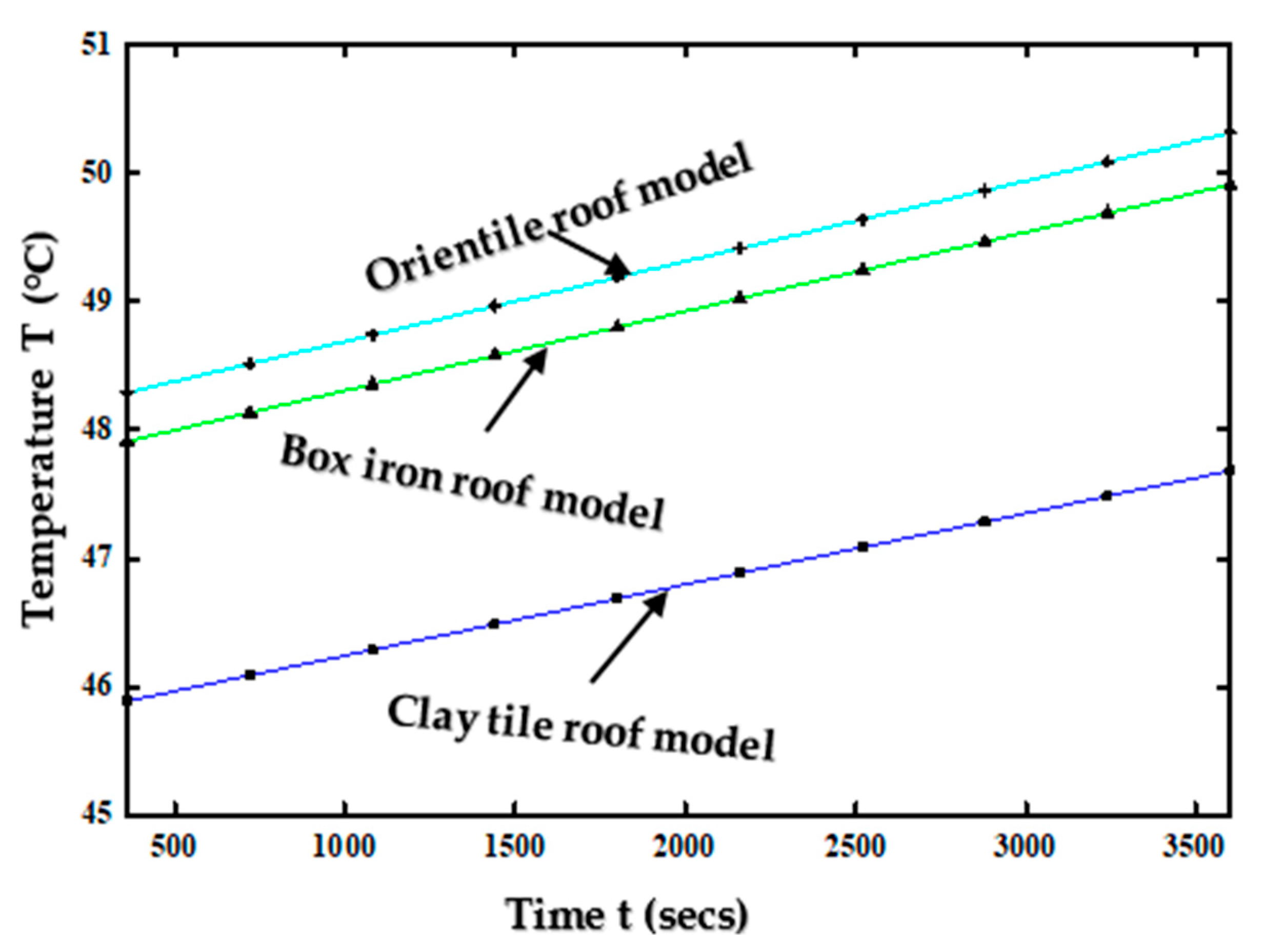
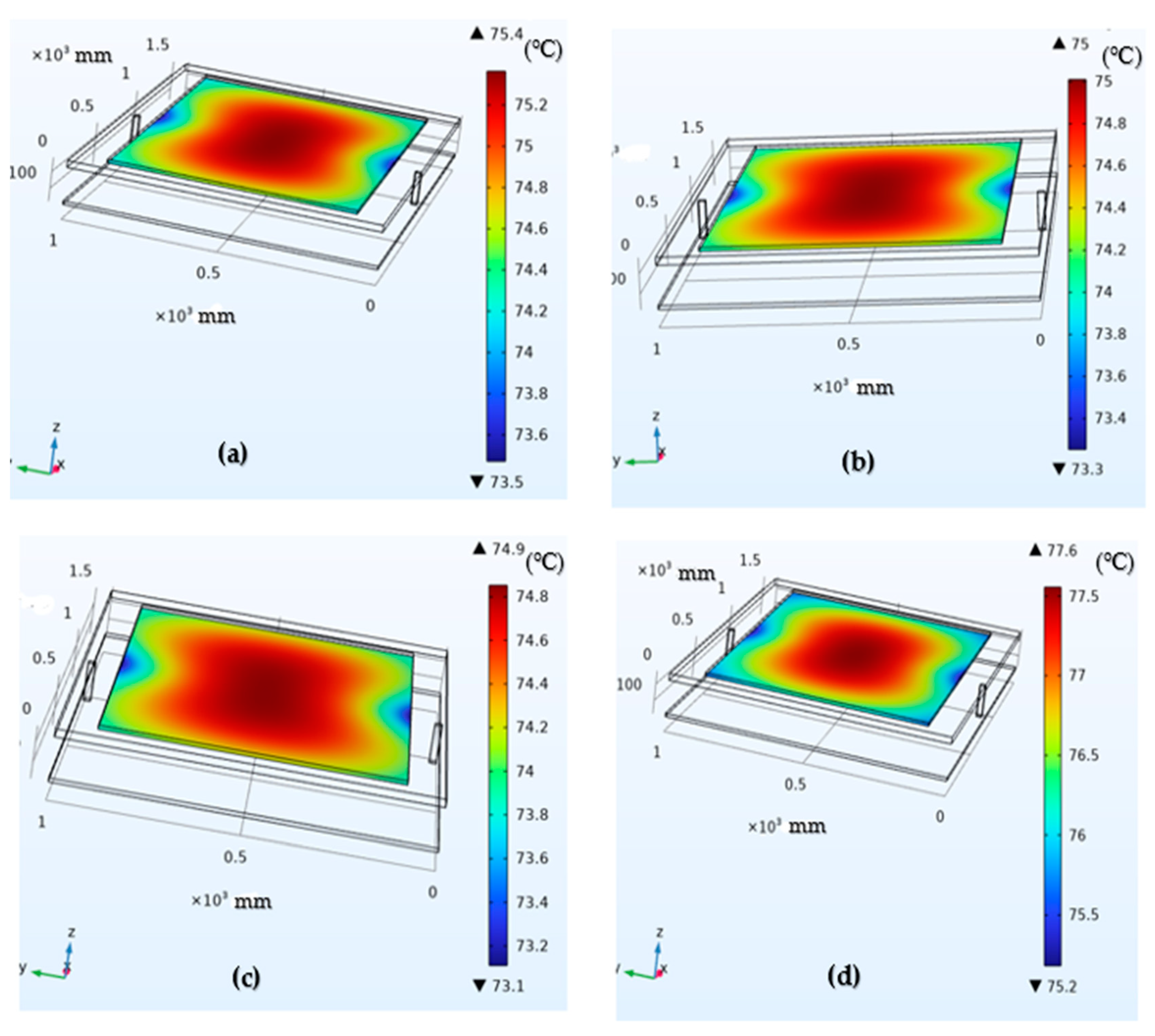
3.2. Effects of Roof Material Geometry

The simulation results give the temperature distribution across the PV modules for the three roof models. Figure 9 shows the temperature distribution for the steady-state thermal analysis of the three roof-PV models (clay tile, Box-profile metal roof and Orientile metal roof). Figure 9 reveals that the temperature of the PV module on the clay tile roof material is lower than that on the metal roofs. However, the Box-iron roof model shows lower PV temperatures when compared to the Orientile model.
The thermal properties of the different roof materials play a key role in the temperature build-up of the models, as seen in Figure 9. It is observed that the highest temperature of the clay roof model is 47.68 °C, while those of the Box-iron and Orientile roof models are 49.91 °C and 50.32 °C. These differences in temperature distribution can have a significant impact on the performance of the PV modules, particularly in large arrays. The difference in maximum PV temperature of the metal roof models (Box-iron and Orientile) is 0.41 °C. This is to be expected, given the similar thermal properties of both metallic roofs. However, this difference cannot be ignored. The difference in design/geometry between the Box-profile and the Orientile metal roofs may be responsible for temperature variations of the PV modules.

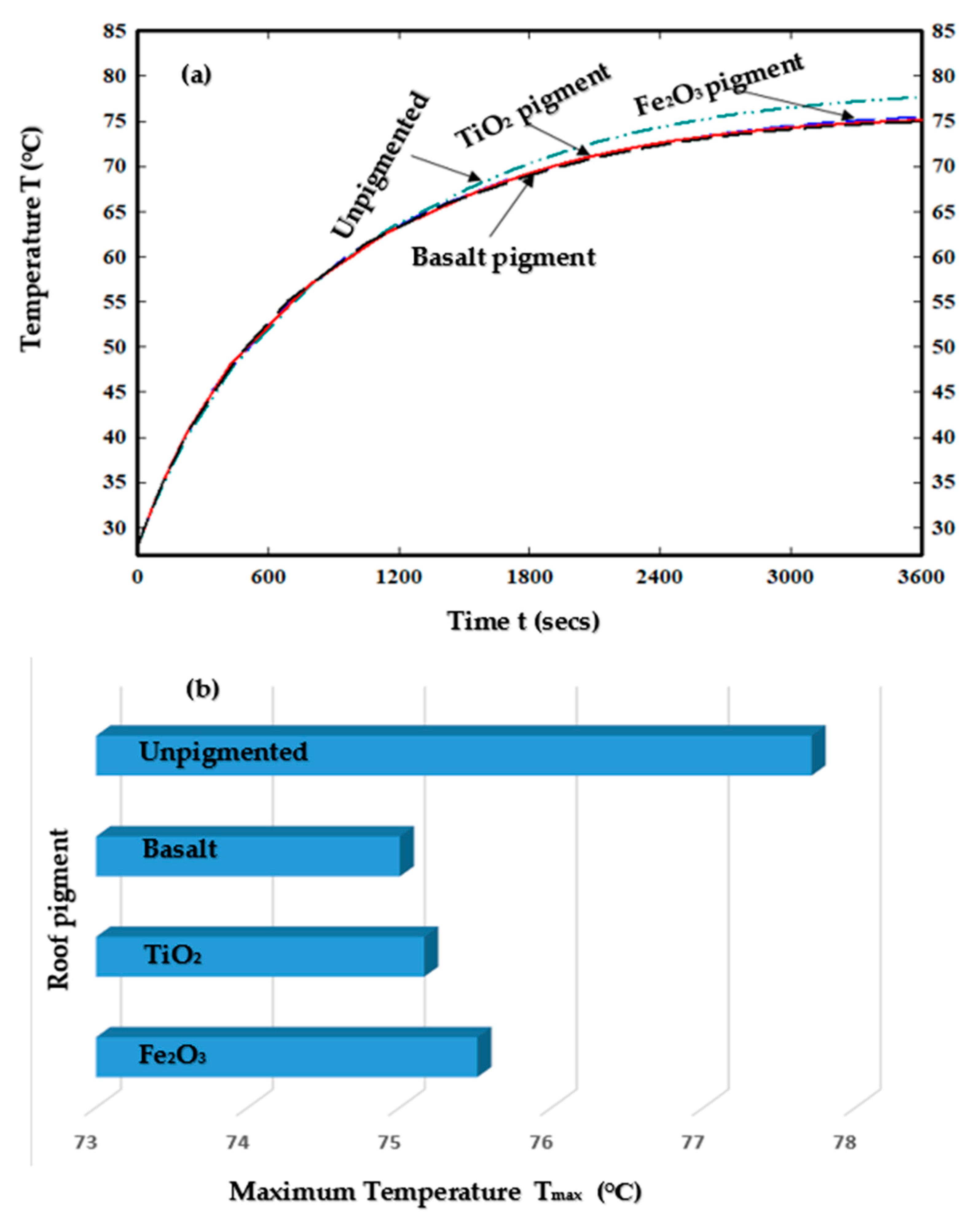
3.3. Effects of Roof Pigmentation

Figure 10 and Figure 11 show cell temperatures for the pigmented roof-PV models of iron iii oxide (Fe2O3), titanium dioxide (TiO2) and basalt (Ba), as well as the unpigmented roof-PV model. The temperature values of Figure 10 and Figure 11 are higher than in Figure 9. This is expected because Figure 10 and Figure 11 show results for the time-dependent simulation study, causing temperatures to rise with time. Figure 10 shows the results from COMSOL time-dependent multi-physics, while Figure 11a further presents the temperature build-up with time on the solar cells. Figure 11b reveals the maximum temperature of the solar cell for each roof-PV model. The results revealed that amongst all the pigmented roof-PV models, the solar cell on the Fe2O3-pigmented roof had the highest temperature, while the temperature of the cell on the TiO2 roof was marginally higher than that on the Ba-pigmented roof. Results also show the heating curves of the temperature build-up for each of the models after 3600 s.
Figure 11a gives similar curve patterns for the temperature build-up in the various models. However, the curve steps are slightly different. The varying steepness of the curves reveals that the rate at which cell temperatures rise at specific times is different for the various models, although they all reach similar temperature values at the end of 3600 s. Within the first 100 s, the cell temperatures were observed to be 34.17 °C, 34.2 °C and 34.17 °C for Fe2O3-, TiO2- and Ba-pigmented roofs, with the cell temperature on the unpigmented model having a value of 33.92 °C. However, after 549 s, the cell temperature of the unpigmented model reaches a value of 62.14 °C, which is higher than the values (62.02 °C, 61.93 °C, 62.09 °C) of the pigmented models. This trend continues for the remaining time of the simulation. After 3594 s, cell temperatures on Fe2O3- and Ba-pigmented roofs reach their maximum of 75.51 °C and 75 °C, respectively, while the cell temperature of the TiO2-pigmented roof reaches its maximum value of 75.16 °C after 3596 s. The unpigmented model reaches a maximum of 77.71 °C after 3600 s. Further, although the cell temperatures for each of the three pigmented models eventually reach similar maximum values (75.51 °C, 75.16 °C, 75 °C) after 3600 s, there exist some variations. Figure 11b makes clear the maximum temperature of the solar cells on each of the pigmented roofs. It is clear that the solar cell on the Fe2O3-pigmented roof reaches the highest temperature of 75.51 °C, which is followed by the cell temperature of the TiO2-pigmented roof with a value of 75.16 °C, and then the cell temperature of the Ba-pigmented roof, which is at a maximum of 75 °C. This indicates that in an array of roof-installed modules, the installation on the basalt-pigmented roof will outperform that on Fe2O3-pigmented roofs and marginally outperform the installation on TiO2-pigmented roofs. The results reveal a higher temperature build-up of the PV modules with the unpigmented roof. The PV cell temperature of the unpigmented model reached a maximum value of 77.71 °C, which is quite significant when compared to the cell temperatures of the pigmented models. This is a temperature gain of 2.2 °C, 2.55 °C and 2.71 °C compared to the Fe2O3-, TiO2- and Ba-pigmented models. These differences are significant, given the importance of a single unit temperature gain or loss on the overall performance of a PV module [38]. It can also be deduced from the results that the majority of the heat transferred from the pigmented roofs is transferred to the surroundings and not to the back sheet of the PV module, thereby allowing the cell temperatures of the pigmented models to exhibit lower temperatures relative to an unpigmented model. The results from this study are similar to the study by Leow et al. [44], a time-dependent CFD simulation study that investigated the temperature build-up of a roof-integrated PV module using ANSYS software. Results from this study revealed a maximum solar cell temperature of 75.66 °C at 1000 W/m2 solar irradiance. This correlates with the findings of this research, as presented in Figure 10 and Figure 11, given that the maximum solar cell of a PV module integrated on a pigmented roof is 75.51 °C (Fe2O3-pigmented roof). Figure 12 displays a graphical representation of this comparison.
The difference in maximum module temperature (0.15 °C) is quite low, indicating that both studies are in agreement. More so, Whitman [46] compared the performance of solar PV modules installed on green roofs with those installed on a black metal roof and white pigment-coated metal roof. Findings from this study revealed that the PV module on the pigmented white roof outperformed that on the black roof due to the reflective properties of the white roof. This is consistent with the findings of this study, given that PV modules on pigmented roofs are predicted to outperform modules on unpigmented roofs.

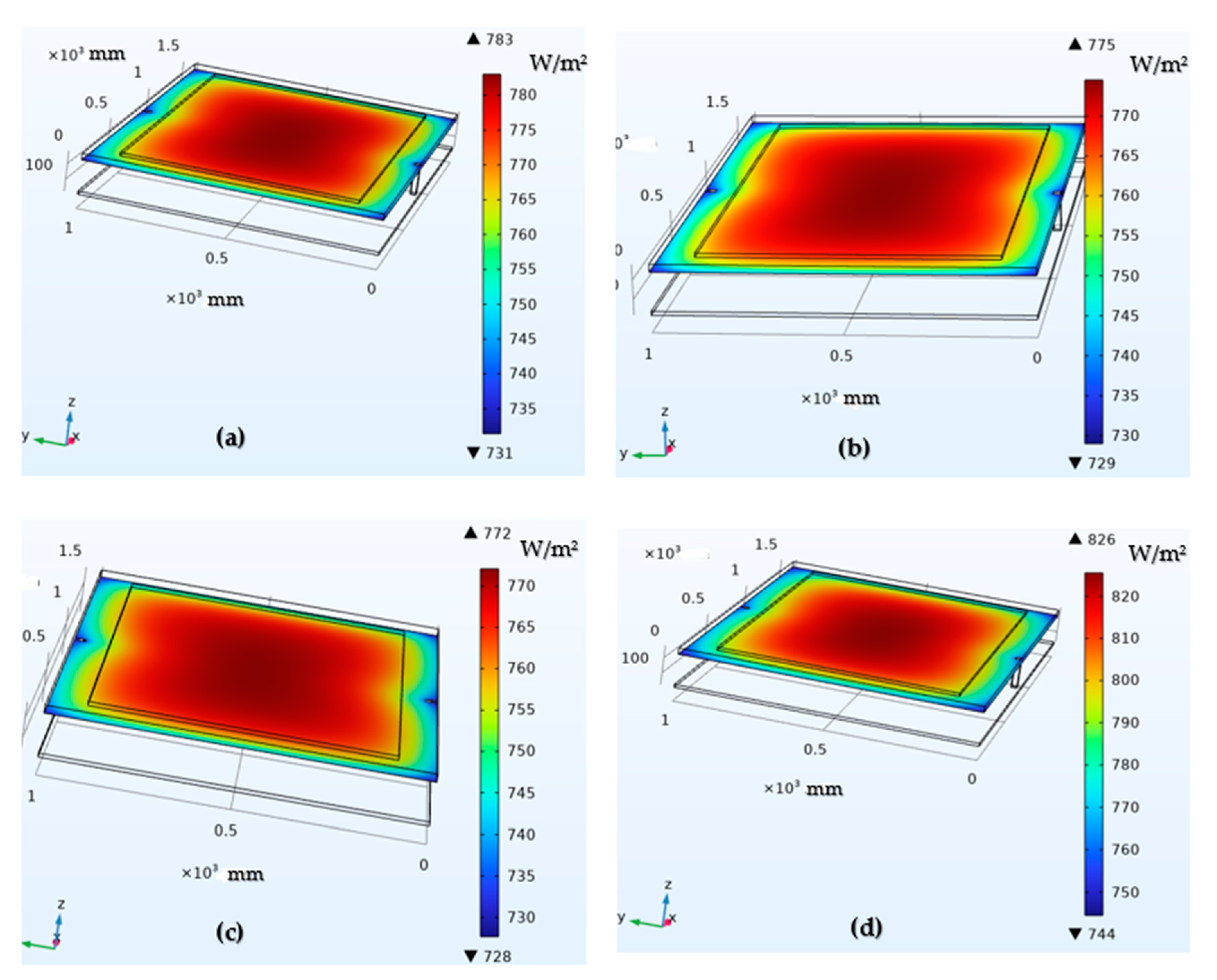
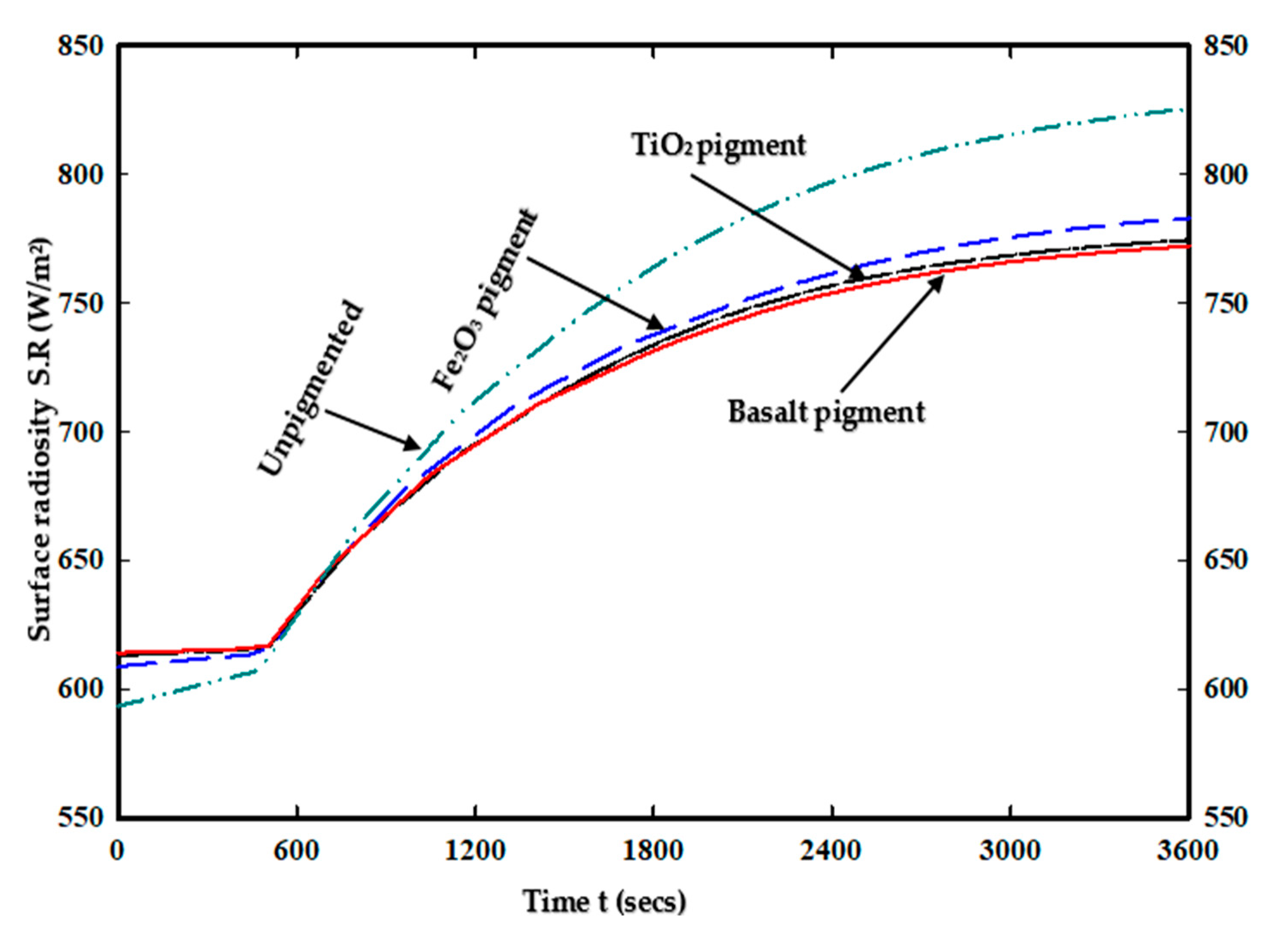
3.4. Surface Radiosity

The surface radiosity of the unpigmented model was studied and compared to that of the pigmented models. Given the higher temperature build-up on the unpigmented model, a higher surface radiosity was expected. Figure 13 shows the simulation results of the surface radiosity of the models, and Figure 14 compares the surface radiosity of all four models. The surface radiosity of the unpigmented model was notably higher than that of the pigmented models. The slight differences observed in the temperature profiles of the pigmented models in Figure 11 may appear inconsequential at first glance. However, further investigation on the surface radiosity of each of the PV systems with different pigment types shows the significance of these temperature differences.
For the pigmented models, the surface radiosity, which tells how much heat is radiated to the surroundings [47], is highest in the PV module with the Fe2O3 pigment with values reaching 783 W/m2 followed by that of TiO2 with a value of 775 W/m2 closely followed by the Ba-pigmented model with the highest recorded value of 772 W/m2. These differences are quite significant, particularly between the Fe2O3-pigmented model and the Ba-pigmented model, having a difference of 11 W/m2 in one hour. From Figure 14, it is observed that at about 590 s, the surface radiosity of all four models seems to converge. But with time and continuous variations in temperature-build, clear differences are observed, and this may be more significant in an array of roof-installed PV modules. The obtained results also reveal a maximum surface radiosity of 825.52 W/m2, which is a gain of 42.52 W/m2, 50.52 W/m2 and 53.52 W/m2 when compared to the surface radiosity of Fe2O3, TiO2 and Ba-pigmented models. This indicates that apart from the predicted relatively lower performance of the PV modules installed on unpigmented roofs, the unpigmented roof assemblies also produce significantly higher radiosity, making it the least environmentally friendly installation.
As demonstrated, among the pigmented models, the Fe2O3-pigmented assembly will radiate the highest amount of heat to the surroundings, and the TiO2 assembly will radiate more heat to the surroundings than the Ba assembly. This shows that the Ba assembly is the most environmentally friendly among the three pigmentation assemblies.

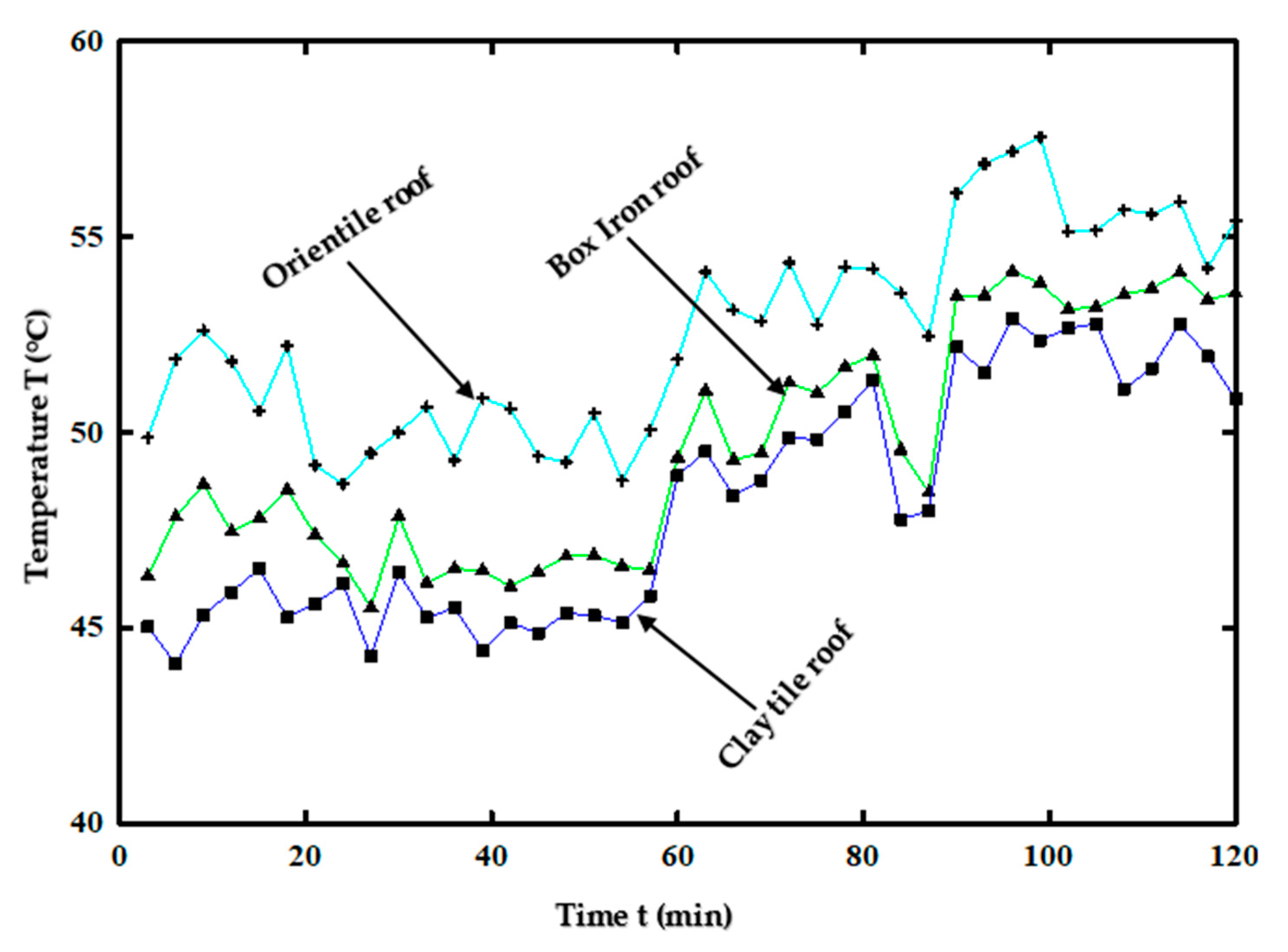
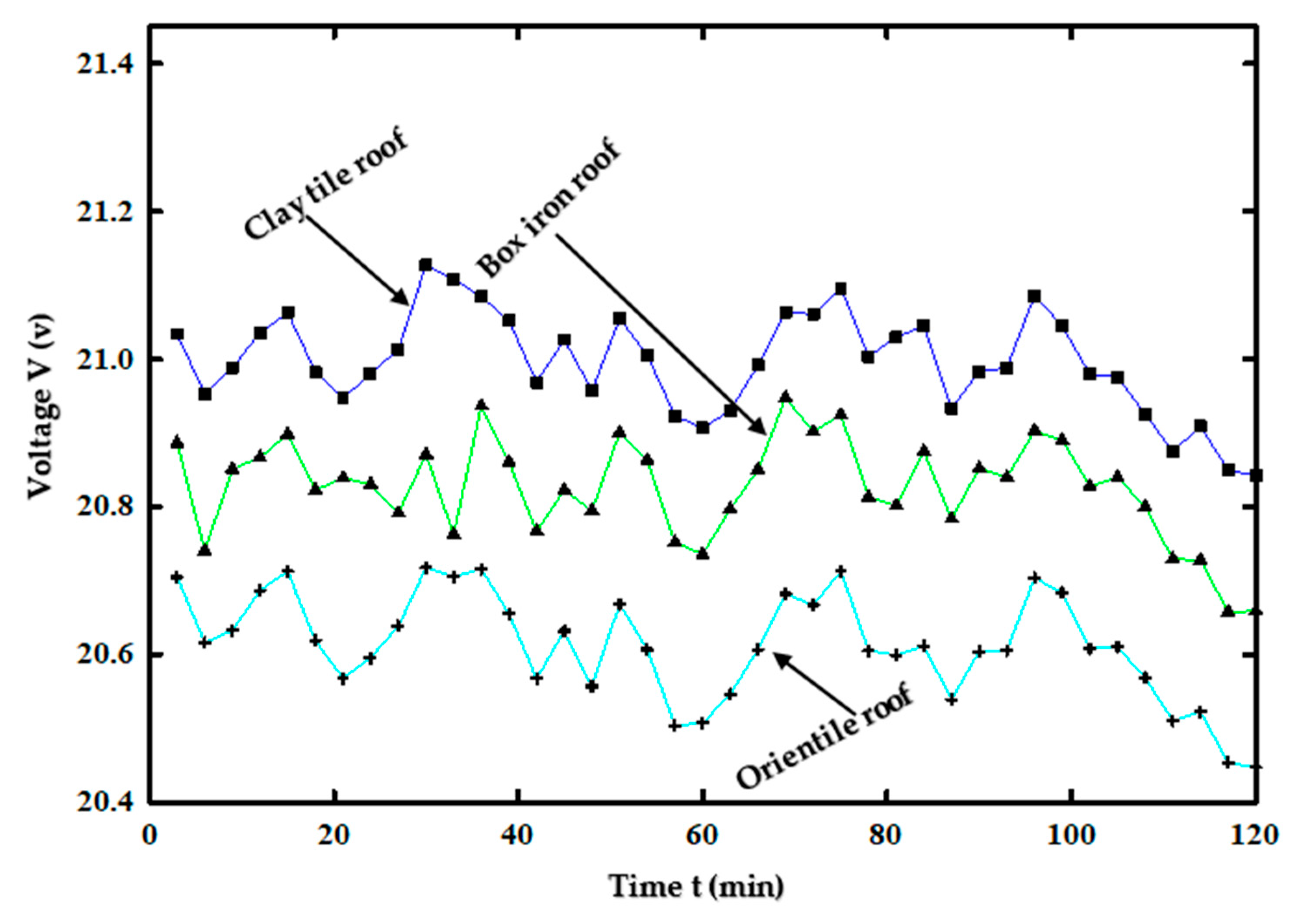
3.5. Experimental Results

Results from the experiment give the practical temperature distribution of the PV modules on each of the roof materials, design and geometry examined. The results conform with the results in Figure 9. Figure 15 shows the temperature distributions of the PV modules from field experiments.
While the results from Figure 9 and Figure 15 follow the same trend, it can be observed that there are fluctuations in the experimental results, preventing a steady increase or decrease in temperature. This is to be expected due to the practical environmental conditions that exist, such as changes in wind speed, ambient temperature and variations in solar irradiation with time. Furthermore, experimental results reveal a visibly higher difference in temperature between the modules on the Box-iron roofing sheet and the Orientile roofing sheet. This is attributed to the shape/geometry of the Box-iron roofing sheet, as seen in Figure 8. The Box-profile sheet is shaped in such a way that it allows for extra cooling through natural convection. This is consequential because it highlights that even similar metal roof materials could lead to different outcomes based on the way they are shaped. The cooling features of the clay tile roof allow the PV temperature on the clay tile roof to be notably lower than those of the metal roofs. The experimental results reported in this study are consistent with the literature. Guimarães et al. [48], in their study, experimentally investigated the peak temperature of PV modules installed on different roof materials: galvanized steel roof and red ceramic roof (base material made of clay). Results revealed that the peak, as well as average temperature of the PV module installed on the galvanized steel roof, was steadily higher than the corresponding temperatures of the module installed on the ceramic roof. This conforms with the experimental results of this study presented in Figure 15, given that the PV modules on the metal roofs recorded higher temperature values than the modules on the clay roof material. The results of the open-circuit voltage of the modules presented in Figure 16 underline the significance of temperature build-ups in modules.
The open-circuit voltage is highest in the PV module installed on the clay roofs, which is the module with the lowest temperature build-up. The open-circuit voltage of the module on the Box-profile metal roof is higher than that on the Orientile roof. The module on the Orientile metal roof undergoes a notable voltage drop, which can result in lower module performance. Over the time of the experiment, the clay roof module reaches a maximum of 21.096 V, the Box-iron roof module reaches a maximum of 20.945 V, and the Orientile roof module reaches a maximum of 20.718 V. It can be deduced that PV modules will fare better on clay tile roofs. Further, the geometric design of Box-profile metal roofs gives them an advantage over Orientile metal roofs when PV performance is taken into consideration.

3.6. Economic Implication and Sustainability

The selection of roofing materials for PV installations may result in varied economic implications. Clay roof tiles, for instance, though with all the benefits already discussed, are hard but brittle. This makes them prone to cracks under loads and needing replacements; otherwise, leakages may occur when it rains. They are very delicate, and affixing solar panels to them comes with major difficulties. This is different for metal roofs, which have good compatibility with PV installations. However, metal roof materials are prone to corrosion, causing them to lose their aesthetic appeal over time. Clay roof tiles are quite expensive, which poses an inherent financial burden due to limited purchasing power. In Kenya, clay tile roofing materials cost, on average, KES 2000 per square meter, indicating that a house with a roofing area of 200 square meters would require KES 400,000 as a cost for roofing. This is significantly higher when compared with metal roofs, which cost, on average, KES 1020 and KES 1200 per square meter for Box-profile metal roof and Orientile metal roof material, respectively. Table 2 presents a clear perspective on the cost implications of the various roof materials as well as provides insights into the environmental impact of the various roof types. The sustainability of a roof material encompasses its raw materials, process of manufacture and method of disposal at the end of its life. Furthermore, roofing material building cooling performance is also a key indicator of sustainability.

4. Conclusions

Simulation and experiments were implemented for the investigation of PV performance on different roof materials, roof geometry and roof pigmentations. Temperature profiles, as well as the open-circuit voltage of solar PV modules assembled on three different roof types (clay tile, Box-profile metal roof, Orientile metal roof), were studied. Further, the potential of roof pigments for improved performance of PV modules on metal roofs was studied. Three common different roof pigmentations comprising Fe2O3, TiO2 and basalt were considered for analysis, and results were compared with results from an unpigmented roof model. Simulation, as well as experimental studies, indicate superior module performance in the clay tile roof installation, with the module on the Orientile metal roof material producing the least desirable output. For the three pigmented models, the highest solar cell temperature was recorded on the Fe2O3-pigmented roof, which was followed by the TiO2-pigmented model and then the basalt model. The unpigmented model, however, gives the highest solar cell temperatures. The temperature differences between the three pigmented models appear to be small, but the investigation of the surface radiosity of the solar cells reveals significant differences in the amount of heat radiated by each model to the surroundings, and these differences may be heightened in an array of modules. The unpigmented model reveals surface radiosity that is significantly higher than that of the pigmented models, making it the least environmentally friendly installation. The results establish that PV modules on clay tile roofs outperform those on metal roofs. However, the performance of PV modules on metal roofs can be improved with the addition of cool pigments and by optimizing the design of the roof shape. The roof geometric design of the Box-profile metal roof pigmented with basalt is therefore recommended for solar PV installations on metal roofs.

Author Contributions

N.A.: conceptualization, investigation, methodology, formal analysis, validation, data curation, and writing—original draft; F.N.: supervision, conceptualization, and writing—review and editing; M.M.: supervision, conceptualization, and writing—review and editing. All authors have read and agreed to the published version of the manuscript.

Funding

This study was funded by the Federal Ministry for Economic Cooperation and Development (BMZ) and accorded to N.A. for his Master’s study (Grant Ref. 91789267).

Institutional Review Board Statement

Not applicable.

Informed Consent Statement

Not applicable.

Data Availability Statement

Data will be made available upon request.

Acknowledgments

The authors also express gratitude to the Department of Energy, Gas and Petroleum Engineering of Kenyatta University for the research equipment.

Conflicts of Interest

The authors declare no conflict of interest.

References

  1. Adounkpe, J.G.; Lawin, A.E.; Ahouannou, C.; Akiyo, R.O.L.; Sinsin, B.A. Modeling Solar Energy Transfer through Roof Material in Africa Sub-Saharan Regions. ISRN Renew. Energy 2013, 2013, 480137. [Google Scholar] [CrossRef]
  2. Roy, K.; Dani, A.A.; Ichhpuni, H.; Fang, Z.; Lim, J.B.P. Improving Sustainability of Steel Roofs: Life Cycle Assessment of a Case Study Roof. Appl. Sci. 2022, 12, 5943. [Google Scholar]
  3. Koumbem, W.N.D.; Ouédraogo, I.; Ilboudo, W.D.A.; Kieno, P.F. Numerical Study of the Thermal Performance of Three Roof Models in Hot and Dry Climates. Model. Numer. Simul. Mater. Sci. 2021, 11, 35–46. [Google Scholar]
  4. Zou, Q.; Li, Z.; Zou, F.; Zeng, X.; Wang, C.; Pan, Y. A study on the characteristics of roof wind field by wind tunnel test. J. Build. Eng. 2021, 43, 103155. [Google Scholar]
  5. Mahdavinejad, M.; Javanroodi, K. Impact of roof shape on air pressure, wind flow and indoor temperature of residential buildings. Int. J. Sustain. Build. Technol. Urban Dev. 2016, 7, 87–103. [Google Scholar] [CrossRef]
  6. Moustafa, W.; Hegazy, I.; Eldabosy, M. Roof geometry as a factor of thermal behavior: Simulation based study of using vaults and domes in the Middle East zone. Int. J. Low-Carbon Technol. 2018, 13, 204–211. [Google Scholar] [CrossRef]
  7. Bottarelli, M.; Bortoloni, M.; Zannoni, G.; Allen, R.; Cherry, N. CFD analysis of roof tile coverings. Energy 2017, 137, 391–398. [Google Scholar]
  8. Cherry, N.; Haig, J.; de With, G. Thermal Benefits of Tiled Roofs with Above-sheathing Ventilation. J. Build. Phys. 2009, 33, 171–194. [Google Scholar]
  9. Di Giuseppe, E.; Sabbatini, S.; Cozzolino, N.; Stipa, P.; D’Orazio, M. Optical properties of traditional clay tiles for ventilated roofs and implication on roof thermal performance. J. Build. Physic 2018, 42, 484–505. [Google Scholar] [CrossRef]
  10. Pisello, A.L. Thermal-energy analysis of roof cool clay tiles for application in historic buildings and cities. Sustain. Cities Soc. 2015, 219, 271–280. [Google Scholar]
  11. D’Orazio, M.; Stazi, A.; Di Perna, C.; Di Giuseppe, E. The physics of vented roofs in hot and temperate climates: Analysis of different strategies for the reduction of energy consumption and the improvement of environmental comfort. In Energy and Buildings: Efficiency, Air Quality and Conservation; Utrick, J.B., Ed.; Nova Science Publishers: Hauppauge, NY, USA, 2011; pp. 349–367. [Google Scholar]
  12. Di Perna, C.; Stazi, F.; Casalena, A.; D’orazio, M. Influence of the internal inertia of the building envelope on summertime comfort in buildings with high internal heat loads. Energy Build. 2011, 43, 200–206. [Google Scholar]
  13. Arsenović, M.; Pezo, L.; Radojević, Z. Response surface method as a tool for heavy clay firing process optimization: Roofing tiles. Process. Appl. Ceram. 2012, 6, 209–214. [Google Scholar] [CrossRef]
  14. Carrascosa, L.A.M.; Facio, D.S.; Mosquera, M.J. Producing superhydrophobic roof tiles. Nanotechnology 2016, 27, 95604. [Google Scholar] [CrossRef] [PubMed]
  15. Lesado, A.; James, A.J. Clay Roofing Tile: A Cool Roof? Open J. Sci. Technol. 2018, 1, 6–8. [Google Scholar] [CrossRef]
  16. Hamzah, N.; Firman, F.; Djalal, M.R. Characteristic Analysis of Solar Panels on Clay and Ceramic Roof Tiles. Prz. Elektrotechniczny 2022, 98, 39–45. [Google Scholar] [CrossRef]
  17. James, R.; Kirby, R. Selecting and Specifying Roof Coatings. Construction Specifier, July 2015. Available online: https://www.constructionspecifier.com/selecting-and-specifying-roof-coatings/#:~:text=The most common types of,asphalt%2C polyurethane%2C and silicone.&text=Acrylic water-based coatings are,white%2C tan%2C and grey (accessed on 25 August 2023).
  18. Saber, H.H. Energy & Buildings Experimental characterization of reflective coating material for cool roofs in hot, humid and dusty climate. Energy Build. 2021, 242, 110993. [Google Scholar] [CrossRef]
  19. Fortuno-Morte, M.; Serna-Gallén, P.; Beltrán-Mir, H.; Cordoncillo, E. A new series of environment-friendly reddish inorganic pigments based on AFeO3 (A = Ln, Y) with high NIR solar reflectance. J. Mater. 2021, 7, 1061–1073. [Google Scholar]
  20. Carrasco-Tenezaca, M.; Jatta, E.; Jawara, M.; Bradley, J.; Pinder, M.; D’Alessandro, U.; Knudsen, J.; Lindsay, S.W. Effect of roof color on indoor temperature and human comfort levels, with implications for malaria control: A pilot study using experimental houses in rural Gambia. Malar. J. 2021, 20, 423. [Google Scholar] [CrossRef]
  21. Maestri, A.; Luis, D.; Lamberts, R.; Guths, S. Energy & Buildings Measurement of solar reflectance of roofs: Effect of paint aging and a discussion on ASTM E1918 standard. Energy Build. 2021, 245, 111057. [Google Scholar] [CrossRef]
  22. Badin, G.; Ahmad, N.; Ali, H.M.; Ahmad, T.; Jameel, M.S. Effect of addition of pigments on thermal characteristics and the resulting performance enhancement of asphalt. Constr. Build. Mater. 2021, 302, 124212. [Google Scholar] [CrossRef]
  23. Pfaff, G. Iron oxide pigments. Phys. Sci. Rev. 2021, 6, 535–548. [Google Scholar] [CrossRef]
  24. Middlemas, S.; Fang, Z.Z.; Fan, P. A new method for production of titanium dioxide pigment. Hydrometallurgy 2013, 131–132, 107–113. [Google Scholar] [CrossRef]
  25. Chakartnarodom, P.; Prakaypan, W.; Ineure, P.; Chuankrerkkul, N.; Laitila, E.A.; Kongkajun, N. Properties and performance of the basalt-fiber reinforced texture roof tiles. Case Stud. Constr. Mater. 2020, 13, e00444. [Google Scholar] [CrossRef]
  26. Zubielewicz, M.; Kamińska-Tarnawska, E.; Ślusarczyk, A.; Langer, E. Prediction of heat build-up of solar reflecting coatings based on physico-chemical properties of complex inorganic colour pigments (CICPs). Prog. Org. Coat. 2011, 72, 65–72. [Google Scholar] [CrossRef]
  27. Badarnah, L. A biophysical framework of heat regulation strategies for the design of biomimetic building envelopes. Procedia Eng. 2015, 118, 1225–1235. [Google Scholar] [CrossRef]
  28. Garshasbi, S.; Santamouris, M. Solar Energy Materials and Solar Cells Using advanced thermochromic technologies in the built environment: Recent development and potential to decrease the energy consumption and fight urban overheating. Sol. Energy Mater. Sol. Cells 2019, 191, 21–32. [Google Scholar] [CrossRef]
  29. Raj, A.K.V.; Rao, P.P.; Divya, S.; Ajuthara, T.R. Terbium doped Sr2MO4 [M = Sn and Zr] yellow pigments with high infrared re fl ectance for energy saving applications. Powder Technol. 2017, 311, 52–58. [Google Scholar] [CrossRef]
  30. Pisello, A.L.; Rossi, F.; Cotana, F. Summer and winter effect of innovative cool roof tiles on the dynamic thermal behavior of buildings. Energies 2014, 7, 2343–2361. [Google Scholar] [CrossRef]
  31. Puesan, C.W.; Mestre, J.L. Technical evaluation of an improved paint coating with NIR pigments designed to reduce thermal discomfort caused by incident solar radiation: Application in the Caribbean area. Energy Procedia 2017, 115, 463–479. [Google Scholar] [CrossRef]
  32. Lv, J.; Tang, M.; Quan, R.; Chai, Z. Synthesis of solar heat-reflective ZnTiO3 pigments with novel roof cooling effect. Ceram. Int. 2019, 45, 15768–15771. [Google Scholar] [CrossRef]
  33. Alshayeb, M.; Chang, J.D. Photovoltaic Energy Variations Due to Roofing Choice. Procedia Eng. 2016, 145, 1104–1109. [Google Scholar] [CrossRef]
  34. Klugmann-Radziemska, E. The effect of temperature on the power drop in crystalline solar cells. Renew. Energy 2003, 28, 2675–2699. [Google Scholar]
  35. Sun, C.; Zou, Y.; Qin, C.; Zhang, B.; Wu, X. Temperature effect of photovoltaic cells: A review. Adv. Compos. Hybrid Mater. 2022, 5, 2675–2699. [Google Scholar] [CrossRef]
  36. Hossain, R.; Ahmed, A.J.; Islam, S.M.; Saha, N.; Debnath, P.; Kouzani, A.Z.; Mahmud, M.P. New Design of Solar Photovoltaic and Thermal Hybrid System for Performance Improvement of Solar Photovoltaic. Int. J. Photoenergy 2020, 2020, 8825489. [Google Scholar] [CrossRef]
  37. Karki, I.B. Effect of Temperature on the I-V Characteristics of a Polycrystalline Solar Cell. J. Nepal Phys. Soc. 2016, 3, 35–40. [Google Scholar] [CrossRef]
  38. Dwivedi, P.; Sudhakar, K.; Soni, A.; Solomin, E.; Kirpichnikova, I. Advanced cooling techniques of P.V. modules: A state of art. Case Stud. Therm. Eng. 2020, 21, 100674. [Google Scholar] [CrossRef]
  39. Dastbelaraki, A.H.; Yaghoubi, M.; Tavakol, M.M.; Rahmatmand, A. Numerical analysis of convection heat transfer from an array of perforated fins using the Reynolds averaged Navier–Stokes equations and large-eddy simulation method. Appl. Math. Model. 2018, 63, 660–687. [Google Scholar] [CrossRef]
  40. Motsanos, G. The Law of Conservation of Energy. Fluid Mech. Open Access 2017, 4, 172. [Google Scholar] [CrossRef]
  41. Bhat, T.; Chevali, V.; Liu, X.; Feih, S.; Mouritz, A.P. Fire structural resistance of basalt fibre composite. Compos. Part A Appl. Sci. Manuf. 2015, 71, 107–115. [Google Scholar] [CrossRef]
  42. Shilenje, Z.; Ongoma, V.; Ogwang, B. Upper Tropospheric and Stratospheric Ozone Over Equatorial East Africa; Case Study of Nairobi County, Kenya. Ethiop. J. Environ. Stud. Manag. 2015, 8, 290. [Google Scholar] [CrossRef]
  43. Miller, W.A.; Desjarlais, A.O. Cool Color Roofs with Complex Inorganic Color Pigments Surface Properties Affecting Reflectance. Resid. Build. Technol. Des. Perform. Anal. Build. Ind. Trends. 2002, pp. 195–206. Available online: www.aceee.org/files/proceedings/2002/data/papers/SS02_Panel1_Paper16.pdf (accessed on 5 September 2023).
  44. Leow, W.Z.; Irwan, Y.M.; Safwati, I.; Irwanto, M.; Amelia, A.R.; Syafiqah, Z.; Fahmi, M.I.; Rosle, N. Simulation study on photovoltaic panel temperature under different solar radiation using computational fluid dynamic method. J. Phys. Conf. Ser. 2020, 1432, 012052. [Google Scholar]
  45. ASTM. AS for T and M. Designation D2244-93: Standard Test Method for calculation of Color Differences from Instrumentally Measured Color; American Society for Testing and Materials: West Conshohocken, PA, USA, 1997. [Google Scholar]
  46. Witman. Quantification of the Passive Cooling of Photo-Voltaics Using a Green Roof; The Pennsylvania State University: University Park, PA, USA, 2010. [Google Scholar]
  47. Sun, Q.; Ji, Y.; Sun, J. Improved Radiation Heat Transfer Model in RELAP5 for Compact Fuel Rod Bundles by the Absorption Factor Modification. Front. Energy Res. 2022, 10, 841631. [Google Scholar]
  48. Guimarães, B.D.S.; Farias, L.; Filho, D.O.; Kazmerski, L.; Sônia, A.; Diniz, A.C. Roof-mounted photovoltaic generator temperatue modeling based on common brazil roofing materials. Renew. Energy Environ. Sustain. 2022, 7, 5. [Google Scholar]
Figure 1. Metal roof samples with different geometries: (a) Orientile metal roof (b) Box-profile metal roof.
Solar 03 00033 g001
Figure 2. Methodology layout.
Solar 03 00033 g002
Figure 3. Modeled roof material types: (a) clay tile roof, (b) Box-profile roof, (c) Orientile roof.
Solar 03 00033 g003
Figure 4. Exploded view of PV module components with pigmented roof surface.
Solar 03 00033 g004
Figure 5. Assembled models: (a) Orientile roof-PV assembled model; (b) model with pigmented roof surface layer.
Solar 03 00033 g005
Figure 6. Meshed models.
Solar 03 00033 g006
Figure 7. Mesh independent test: (a) Mesh independent test with Orientile roof model. (b) Mesh independent test with Fe2O3-pigmented model.
Solar 03 00033 g007
Figure 8. Experimental setup.
Solar 03 00033 g008
Figure 9. Cell temperature distribution for different roof-PV assemblies.
Solar 03 00033 g009
Figure 10. Solar cell temperatures for pigmented and unpigmented roof-PV model assemblies: (a) roof with Fe2O3 pigment; (b) roof with TiO2 pigment; (c) roof with Ba pigment; (d) unpigmented roof.
Solar 03 00033 g010
Figure 11. Cell temperature curves and maximum temperatures for pigmented and unpigmented roof-PV models: (a) cell temperature curves; (b) maximum cell temperatures.
Solar 03 00033 g011
Figure 12. Maximum solar PV temperature comparison with the literature [44].
Solar 03 00033 g012
Figure 13. Surface radiosity for pigmented and unpigmented roof-PV model assemblies: (a) roof with Fe2O3 pigment; (b) roof with TiO2 pigment (c); roof with Ba pigment; (d) unpigmented roof.
Solar 03 00033 g013
Figure 14. Surface radiosity accretion with time for pigmented and unpigmented roof-PV model assemblies.
Solar 03 00033 g014
Figure 15. Experimental PV module temperature build-up for different roof-PV assemblies.
Solar 03 00033 g015
Figure 16. Solar PV open-circuit voltage variations with time for various roof-PV assemblies.
Solar 03 00033 g016
Table 1. Material properties.
MaterialThickness (mm)Thermal Conductivity (W/m-K)Specific Heat Capacity (J/kg-K)Density (kg/m3)Emissivity
Glass31.85003000--
Eva0.50.352090960--
Solar cell0.41486772330--
Tedlar0.10.2125012000.71
Aluminum frame202049962707--
Clay roof tile15.260.9887817020.88
Box-profile metal roof0.278046078000.71
Orientile metal roof0.348450267300.78
Galvanized iron roof sheet0.358046078000.3
Iron oxide (Fe2O3) pigmentation0.41265052400.74
Titanium oxide (TiO2) pigmentation0.48.369042300.87
Basalt pigmentation0.40.03585027500.9
Table 2. Roof material cost and environmental consequences.
Roofing MaterialCost per Square Meter (KES)Total Cost for 200 Square Meters (KES)Cost of Maintenance and RepairEnvironmental ImpactSustainability
Clay tile roof2000400,000HighEnvironmentally friendlyGood
Box-Profile metal roof1020204,000LowNoisy during rainfallPoor
Orientile metal roof1200240,000LowNoisy during rainfall, heat accumulation under intense heatPoor
Disclaimer/Publisher’s Note: The statements, opinions and data contained in all publications are solely those of the individual author(s) and contributor(s) and not of MDPI and/or the editor(s). MDPI and/or the editor(s) disclaim responsibility for any injury to people or property resulting from any ideas, methods, instructions or products referred to in the content.

