Article

Nonlinear Fault-Tolerant Vibration Control for Partial Actuator Fault of a Flexible Arm

The Graduate School of Engineering, Tokyo University of Agriculture and Technology, Tokyo 184-8588, Japan
*
Author to whom correspondence should be addressed.
Dynamics 2023, 3(2), 234-249; https://doi.org/10.3390/dynamics3020014
Submission received: 23 March 2023 / Revised: 11 April 2023 / Accepted: 14 April 2023 / Published: 17 April 2023

Abstract

:
This paper presents a nonlinear fault-tolerant vibration control system for a flexible arm, considering partial actuator fault. A lightweight flexible arm with lower stiffness will inevitably cause vibration which will impair the performance of the high-precision control system. Therefore, an operator-based robust nonlinear vibration control system is integrated by a double-sided interactive controller actuated by the Shape Memory Alloy (SMA) actuators for the flexible arm. Furthermore, to improve the safety and reliability of the safety-critical application, fault-tolerant dynamics for partial actuator fault are considered as an essential part of the proposed control system. The experimental cases are set to the partial actuator as faulty conditions, and the proposed vibration control scheme has fault-tolerant dynamics which can still effectively stabilize the vibration displacement. The reconfigurable controller improves the fault-tolerant performance by shortening the vibration time and reducing the vibration displacement of the flexible arm. In addition, compared with a PD controller, the proposed nonlinear vibration control has better performance than the traditional controller. The experimental results show that the effectiveness of the proposed method is confirmed. That is, the safety and reliability of the proposed fault-tolerant vibration control are verified even if in the presence of an actuator fault.

1. Introduction

Flexible arms with shapes similar to human arms and a high degree of freedom are currently the most utilized industrial robots. Lightness and stiffness are conflicting properties in material mechanics. Certain features, e.g., light weight and weak rigidity cause problems such as being prone to vibration in the flexible arm. Research on vibration suppression has been especially important in high-precision control systems. The state-of-the-art literature related to vibration suppression provided the realization of fast and high accuracy with advanced control technology [1]. An auxiliary fuzzy compensation is presented to prevent the robot from the failure for a one-wheel mobile robot in [2]. In [3], the authors give an active vibration control method for structures based on magnetic levitation (MAGLEV) technologies to consume vibration energy. In [4], vibration and position control of a flexible beam structure are adopted by shape memory alloy (SMA) wire actuators. The performance analysis of a thin dielectric elastomer actuator with three degrees of freedom was carried out experimentally in [5].
Since numerous smart materials have been developed and emerged in recent decades, smart actuators are notably superior to classical actuators in that they have a simple structure, light weight, and high energy efficiency. Smart materials’ properties can be significantly changed by external stimuli, such as stress, electric fields, magnetic fields, and temperature; the corresponding smart actuators are namely piezoelectric (PZT), electrostrictive, magnetostrictive and shape memory alloys (SMA) actuators, respectively. In [6], a flexible bending actuator using SMA is designed and its integration with solar sailing attitude control is discussed. Some researchers have focused on vibration control using smart actuators [7]. In particular, due to the hysteresis nonlinearity of smart actuators, the vibration control system will experience undesired oscillations and even instability. Therefore, hysteresis compensation for SMA actuator-based vibration control is an important issue for realizing desired control. For example, in [8], an inverted pendulum-structured water tower using shape memory alloys for actuation reduced the seismic requirements on concrete columns. In [9], the utility of SMA actuators and PZT actuators are favorable for realizing low and high-frequency modes of vibration control. An inflatable rubber tube with an uncertain soft actuator is introduced in [10].
Furthermore, automatic control systems are prone to faults. The safety and reliability of systems are required in safety-critical applications [11], such as hexacopter [12], Near-Space Hypersonic Vehicles (NSHVs) [13], robotic manipulators [14], microreactors [15], Wireless Power Transfer (WPT) systems [16], and so on. For sensor fault of microreactor systems actuated by a Peltier device, fault detection and fault tolerant schemes use one-class support vector machine (SVM) [17]. The general classifications of faults are sensor fault, actuator fault [18], and plant fault. For the complicated structural components, structural safety has been investigated by real-time and visible monitoring of fatigue crack detection based on computer vision and machine learning approaches in [19]. For a double-layered tank system, the fault is detected early based on SVM combined with ChangeFinder [20]. The overview of the actuator’s fault tolerant control includes linear system [21], nonlinear system [22], and systems with time delay [23]. Fault-tolerant control (FTC) for a three-tank system is designed based on a reconfigurable reference input [24]. Sliding mode FTC dealing with modeling uncertainties is reported for actuator faults in [25]. An actuator-integrated fault estimation (FE) and FTC design was constructed to ensure the safety and reliability of the electric power steering (EPS) system of the forklift in [26].
As mentioned above, the survey of the literature has provided broad perspectives and advanced technologies for the current study and new developments and applications in smart actuator-based vibration control and FTC systems. In the research group’s previous works, a flexible arm’s load-attached vibration issue is discussed by single-sided SMA actuation. Subsequently, a double-sided SMA actuator is applied to the operator-based n-times feedback loops for improving the tracking performance. Moreover, a vibration controller integrated with a designed integral compensator is developed in [27]. It is a step-by-step research progress. The connection with research results shows that SMA actuators can be used to suppress the vibration of the flexible arm. The current study considers actuator faults; the safety and reliability of the vibration control system need to be tolerance faults. The novelty of our research is the proposal of a nonlinear fault-tolerant vibration control system for a flexible arm in case of actuator faults. The challenges in solving the problem are robust stability and tracking performance of vibration control in the event of actuator faults. This research is motivated by the vibration of the flexible arm and fault tolerance with partial actuator fault. The purpose of this paper is to control the vibration of a flexible arm using a double-sided interactive SMA actuator considering the actuator fault. According to the modeling of the flexible arm, the vibration controller and a hysteresis compensator based on operator theory are designed for robust stability and tracking performance. Meanwhile, to improve safety and reliability in the vibration-controlled system, the fault-tolerant dynamics are discussed when a partial actuator failure scenario occurs. The main contributions of this paper can be highlighted as follows:
1.
The double-sided interactive SAM actuator is used for vibration suppression of the load-attached flexible arm with the partial actuator fault.
2.
Robust stability and the desired tracking performance of the nonlinear vibration control system have improved by the reconfigurable controller even if in the presence of an actuator fault.
3.
Fault-tolerant dynamic is carried out for partial actuator fault by experiment results.
The remainder of this paper is outlined as follows: Section 2 introduces the preliminary works, basic theory and problem statement; Section 3 describes the nonlinear fault-tolerant vibration control system; Section 4 carries out the experimental case study and discussion; finally, the conclusion is given in Section 5.

2. Preliminaries and Basic Theory

This section mainly introduces some preliminaries and basic theory, including modeling of the flexible arm with interactive SMA actuator, operator theory, and fault-tolerant control, then the problem set is given.

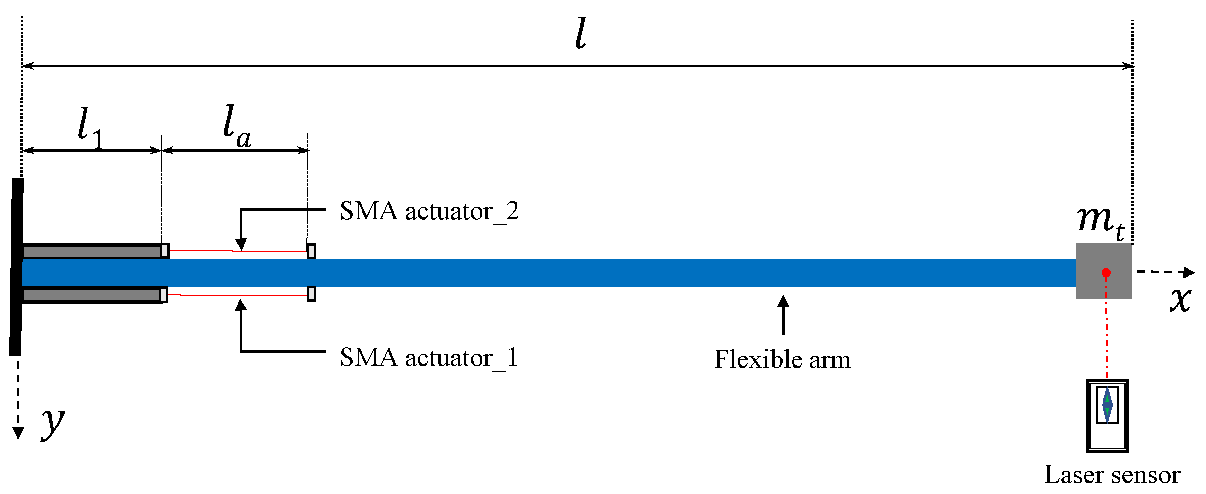
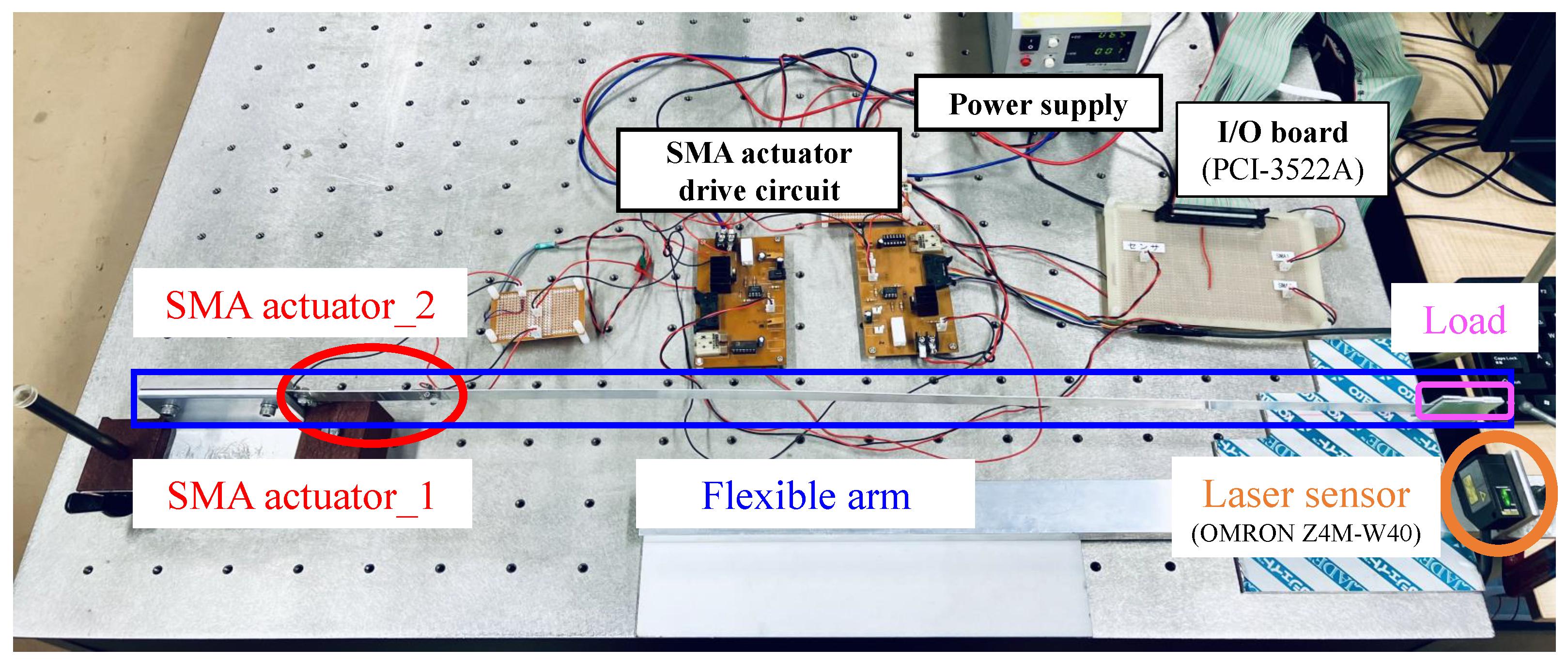
2.1. Overview of the Flexible Arm

A flexible arm is a rigid structure with one end fixed and another end free. The modeling of a flexible arm can be viewed as the cantilever beam whose one end is cast or anchored to a vertical support. In this paper, the flexible arm as shown in Figure 1 is made of aluminum with the left end being the support and the right end being the cantilevered end. A load is attached to the free end of the arm with a mass of 0.022 kg. Two SMA wires are installed on both sides of the arm at a certain distance from the base point. The Z4M-W40 laser displacement sensor is placed at the free end to measure the vibration displacement of the arm, and the distance between the measurement point is 40 mm. The flexible arm is divided into the vibration model of a load-attached flexible arm, the thermal model and PI hysteresis model of an SMA actuator.

2.2. Vibration Model of the Load-Attached Flexible Arm

The vibration dynamics of the arm can be expressed as following the Euler-Bernoulli beam theory (1). Parameters of the load-attached flexible arm are presented in Table 1.
Table 1. Parameters of the load-attached flexible arm.
DescriptionParameters [Unit]Value
Density ρ [ kg / m 3 ] 2700
Cross-sectional area S [ m 2 ] 10 × 10 6
Young’s modulus E [ N / m 2 ] 6.9 × 10 10
Moment of inertia of area I [ m 4 ] 1.67 × 10 12
First order damping modulus C 1 [ s ] 0.0015
Position of SMA l 1 [ m ] 0.1
Length l [ m ] 0.8
Mass of load m [ Kg ] 0.022
ρ S 2 y a ( x , t ) t 2 + 2 x 2 E I 1 + C m t 2 y a ( x , t ) x 2 = 2 x 2 M a ( t ) δ ( x l 1 )
Then, by the assumed modes approach, the vibration displacement of the flexible arm y a ( x , t ) (2) can be obtained from the first vibration mode to infinite mode, where the vibration modal function ω m can be expressed by the following equation using the obtained eigenvalues (3).
y a ( x , t ) = m = 1 J m 0 t e α m 2 ( t τ ) · sin β m 2 ( t τ ) · M a ( τ ) d τ
ω m ( x ) = B m ( cosh λ m l + cos λ m l ) ( cosh λ m x cos λ m x ) ( sinh λ m l sin λ m l ) ( sinh λ m x sin λ m x )
where B m is an arbitrary constant. The following equation is obtained from the orthogonality of vibration modes.
0 l ω m ( x ) ω n ( x ) d x = 0 , ( m n ) ψ m , ( m = n )
where J m , α m , β m , k m is described as follows, respectively.
J m = 2 ω m ( x ) ρ S ψ m β m ω m ( l 1 ) , α m = k m 2 C m β m = 4 k m 2 k m 4 C m 2 , k m = λ 4 E I ρ S
Note: the subscript m indicates the m order vibration mode.

2.3. Thermal Model of the Interactive SMA Actuator

The thermal model describes the relationship between temperature and electric power, is presented by the heat conduction equation as follows (5).
m c p d ( u ( t ) T 0 ) d t = i 2 ( t ) R h c A c ( u ( t ) T 0 )
For convenience, the electric power is the input of the thermal model defined as u d .
u d ( t ) = i 2 ( t ) R
Solving the above Equations (5) and (6), the thermal model is transformed as follows (7).
u ( t ) = T a ( u d ) ( t ) = 1 m c p 0 t e γ ( t τ ) u d ( τ ) d τ + T 0
γ = h c A c m c p

2.4. PI Hysteresis Model of the Interactive SMA Actuator

Prandtl-Ishlinskii (PI) described the hysteresis model of the SMA actuator in [28]. The parameters of the load-attached flexible arm are described in Table 2.
The play hysteresis operator can be described as follows.
F h ( u ) ( t ) = u ( t ) + h , if u ( t ) F h ( u ) ( t i ) h F h ( u ) ( t i ) , if h < u ( t ) F h ( u ) ( t i ) < h u ( t ) h , if u ( t ) F h ( u ) ( t i ) + h
u * denotes the relationship between the PI hysteresis model and the flexible arm,
u * ( t ) = H a ( u ) ( t ) + Δ P I ( u ) ( t )
where the H a ( u ) ( t ) is invertible part, Δ P I ( u ) ( t ) is regarded as disturbance as follows.
H a ( u ) ( t ) = K · u ( t )
K = h 0 h x p ( h ) d h
Δ P I ( u ) ( t ) = h 0 h x S n h p ( h ) d h + h x H p ( h ) F h [ u ] ( t i ) d h
S n = 1 , if u ( t ) F h [ u ] ( t i ) 0 1 , if u ( t ) F h [ u ] ( t i ) < 0
The density function is indicated as follows.
p ( h ) = a × e b ( h 1 ) 2
where the weight parameters that a is 0.0012 and b is 2.8, identified by the experimental data. h x is the maximum number which satisfies the condition, h | u ( t ) F h [ u ] ( t i ) | . h is set as the threshold value.
Based on Mohr’s theorem, the bending moment M a that SMA gives to the flexible arm is derived as follows.
M a ( t ) = 3 E I l 1 2 · u * ( t )

2.5. Operator Theory

Operator theory is used for nonlinear control system analysis and design in view of the input-output nature of the nonlinear system concept itself. Based on the operator theory, nonlinear feedback control systems using robust right coprime factorization have been a promising technique. An operator-based nonlinear feedback control system for the perturbed plant is illustrated in Figure 2, where the overall plant includes the nominal plant P and perturbation P .
  • Right factorization
  • The given plant operator P: UY is said to have a right factorization if there exist two stable operators D: WU and N: WY, such that D is invertible and P = N D 1 . The linear space W is called a quasi-state space.
  • Right coprime factorization
  • If there exist two stable operators A: YU and B: UU satisfying the Bezout identify
    A N + B D = M
    where the operator B is invertible, M Γ ( W , U ) is the unimodular operator.
Remark: let Γ ( W , U ) be the set of stable operator mapping from W to U, there exists a subset defined by
I ( W , U ) = { M : M Γ ( W , U ) , w i t h M 1 Γ ( U , W ) }
Then, elements of the subset I ( U , Y ) are called unimodular operators.
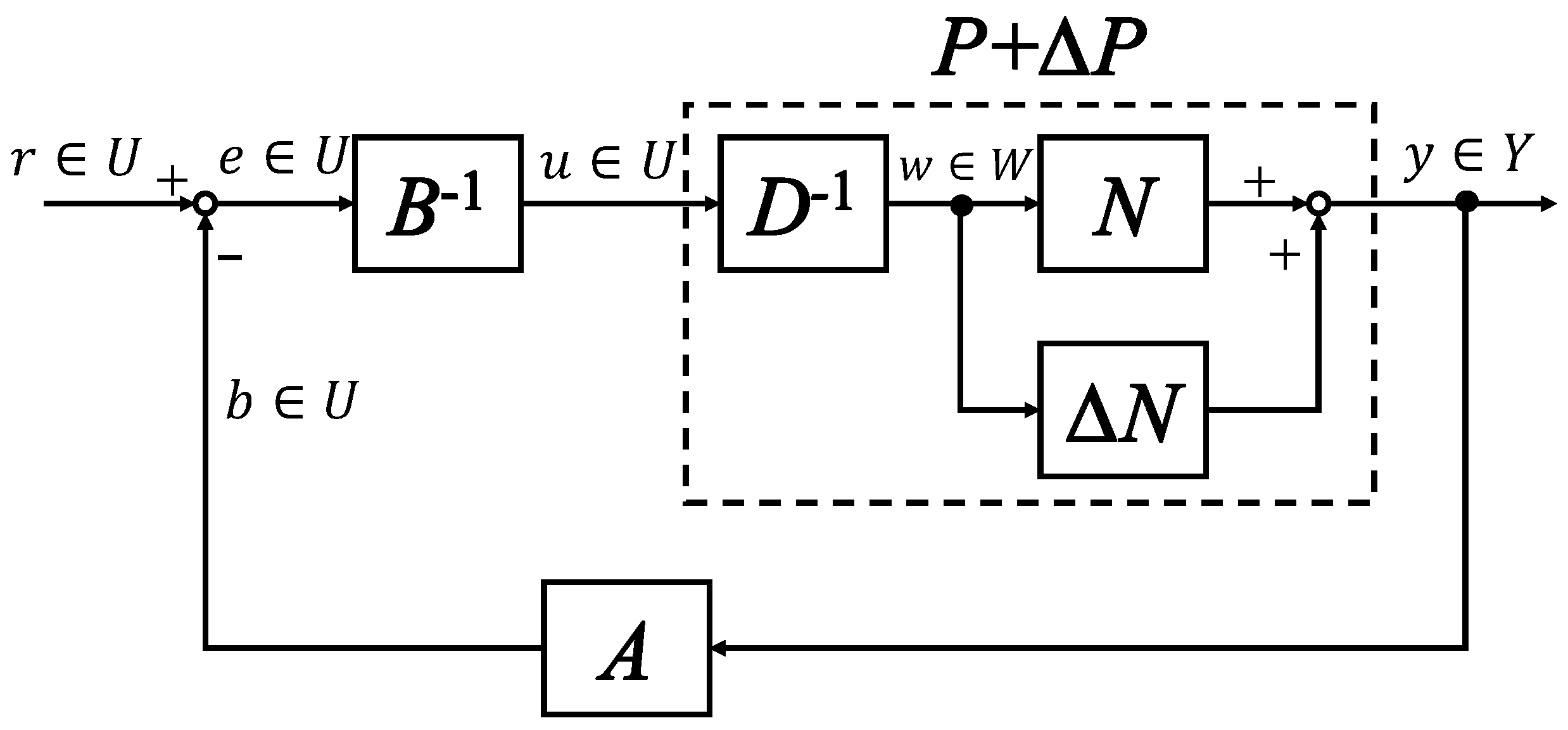
  • Robust right coprime factorization
  • In Figure 2, the Bezout identity for the given plant with uncertainty is formulated by
    A ( N + N ) + B D = M ˜
  • The system is said to have robust stability property if the corresponding control system with uncertainty remains stable. Generally speaking, if R ( A ) W ( A ) , where W ( A ) is a null set defined by
    W ( A ) = { x : x D ( A ) , A ( y + x ) = A y f o r a l l y D ( A ) }
  • Δ denotes unknown bounded uncertainty. A sufficient condition of robust stability for right coprime factorization was proposed in [29]. If the designed operators are satisfied
    ( A ( N + Δ N ) A N ) M 1 L i p < 1
    where | | · | | L i p denotes the generalized Lipschitz operator. Then, the system is robust and stable for uncertainty N .
Figure 2. A nonlinear feedback control system with uncertainty.
Dynamics 03 00014 g002

2.6. Fault-Tolerant Control

The main objective of fault-tolerant control (FTC) is to accommodate various types of system component faults while the safety critical system is operating and maintaining stability even as compromising performance levels with minimal or tolerable degradation [30]. FTC is presented as an integral part of every safety-related system to avoid service failures, especially in airplanes and nuclear facilities, oil and gas, and fertilizers. FTC is divided into active and passive methods [31]. Usually, an active FTC system is integrated with fault detection and isolation (FDI), fault detection and diagnosis (FDD), and a reconfigurable controller (RC). In [32], the reconfiguration controller is based on the output of the FDI or FDD unit to redesign the control loop and to adapt the controller to faulty conditions. The reconfigurable flight control systems are introduced in [33,34,35,36]. The fault nature is such that the fixed predefined faults are accommodated in a passive FTC system. Hardware redundancy is also applied for fault tolerance. In the literature [37], the concept of the resilient robot is feasible for fault-tolerant strategies in terms of structure change, that is, a resilient robot can recover its function dealing with the robot partially damaged, which allows the possibility that the system may still work even if the actuator is damaged.
Fault tolerance is a vital control design element for vibration suppression to maintain system stability with acceptable performance in the case of actuator and sensor faults. The vibration control with an adaptive fault-tolerant boundary controller is investigated for a flexible aircraft wing system in the presence of unknown loss of actuator and sensor effectiveness fault in [38]. An event-triggered adaptive fault-tolerant controller based on the partial differential equation (PDE) model is suggested for the flexible manipulator with two actuators in consideration of the network’s limited communication issue and anticipated actuator failures in [39]. The closed-loop system achieves position tracking and vibration suppression for a rigid-flexible manipulator system (RFMS) suffering from unknown actuator faults in [40]. A fault-tolerant attitude controller based on a modified fast nonsingular terminal sliding mode control (MFNTSM) is used to realize attitude tracking and error trajectories’ finite-time convergence of a class of flexible spacecraft for actuator-related faults in [41]. Nonlinear modeling and adaptive boundary vibration control are investigated for a flexible rotatable manipulator with actuator failure in [42].

2.7. Problem Setup

In this research, the vibration problem of the flexible arm arises from the weak rigidity due to its light weight. Using smart materials as double-sided interactive actuators for vibration control, the nonlinear hysteresis behavior of the SMA actuator will reduce the control accuracy, so the control system should design a hysteresis compensator. In order to increase the security of the system, fault tolerance dynamic analysis is also considered. For the flexible arm with smart actuators, the vibration control system needs to consider three factors: nonlinear robust stability, tracking performance and safety. That is, fast vibration control of the flexible arm, compensation hysteresis of the SMA actuator, and fault tolerance for partial actuator fault.

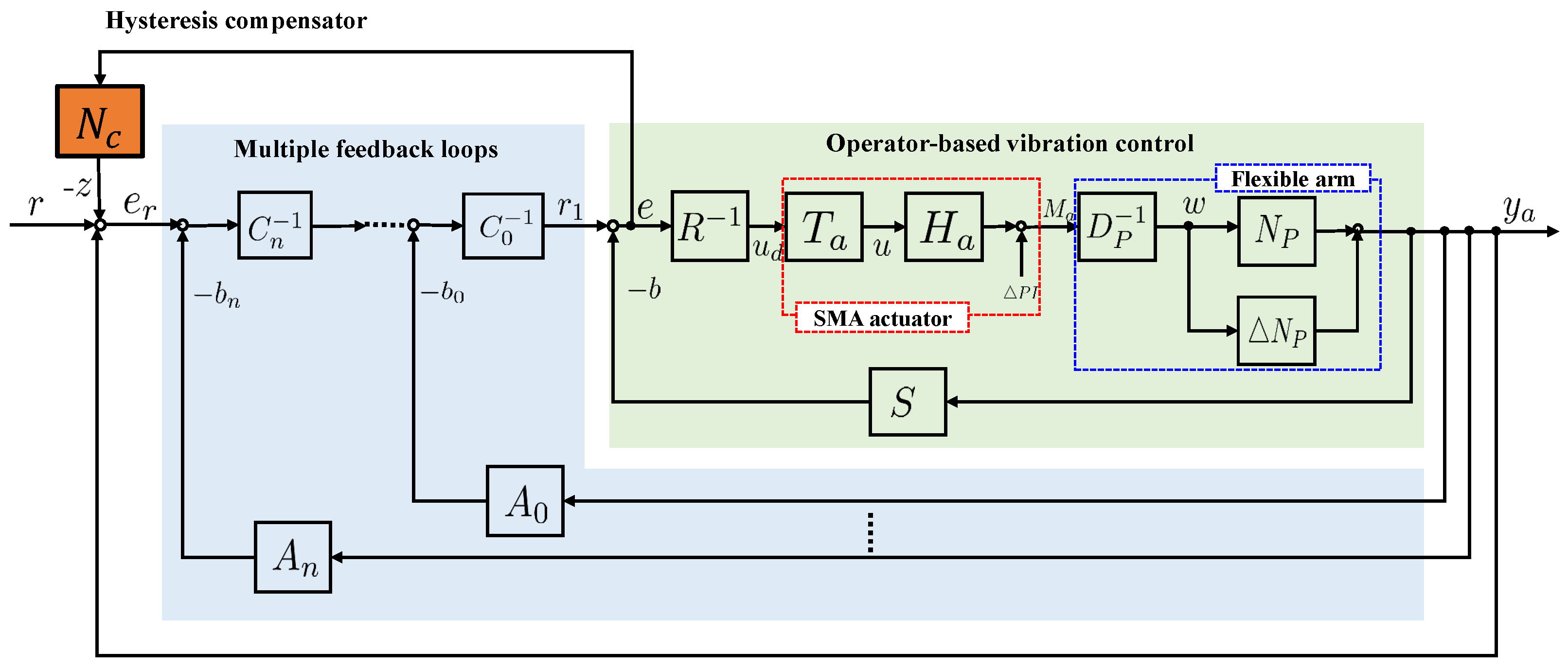
3. Nonlinear Fault-Tolerant Vibration Control System

According to the obtained models of the flexible arm, the framework of the proposed fault-tolerant vibration control system is shown in Figure 3, in which an operator-based robust nonlinear vibration control system is integrated by a double-sided interactive controller actuated by the SMA actuators, a designed hysteresis compensator, and a desired tracking controller using multiple unimodular operators. For the considered fault, the reconfigurable controller is active to improve the fault-tolerant dynamics once the actuator loses input power.
In short, the robust stabilization and the desired tracking performance of nonlinear vibration control will be discussed in both normal conditions and faulty conditions. There are three subsections as follows.
  • Nonlinear vibration controller is to guarantee robust stabilization by using robust right coprime factorization.
  • The hysteresis compensator is to eliminate the effect of hysteresis behavior.
  • The tracking controller and the reconfigurable controller can be obtained by multiple feedback loops even if in the presence of a fault.
For this framework, the subscript P indicates the operator of the plant, while the subscript a indicates the operator of the actuator.

3.1. Operator-Based Fault-Tolerant Vibration Control

The first-order vibration mode is regarded as the nominal plant, and the unconsidered modes are regarded as plant uncertainties. Then, the normal plant has the right factorization as follows.
P ( M a ) ( t ) = N P D P 1 ( M a ) ( t )
N P ( w ) ( t ) = J 1 0 t e α 1 2 ( t τ ) sin β 1 2 ( t τ ) · w ( τ ) d τ
D P ( w ) ( t ) = w ( t )
A new invertible operator D ˜ 1 is defined as follows by the thermal model T a , the invertible hysteresis model of SMA H a and the D P 1 which is obtained by right factorization.
D ˜ 1 ( u d ) ( t ) = D P 1 H a T a ( u d ) ( t )
Then, designing operators S and R to satisfy the Bezout identity shown as follows guarantees that the nominal plant is BIBO stable.
S N P + R D ˜ = I
where I is an identity operator. Designed operators S and R are described as follows.
S ( y a ) ( t ) = K 1 N P 1 ( y a )
R ( u d ) ( t ) = ( 1 K 1 ) D ˜ 1 ( u d ) ( t )
where K 1 ( 0 < K 1 < 1 ) are the design parameters. y a is the output of the overall plant.
If the following Bezout identity (28) and robust stability conditions (29) are satisfied, the robust stability of the proposed nonlinear vibration control system can be guaranteed.
S ( N P + Δ N P ) + R D ˜ = I ˜
[ S ( N P + Δ N P ) S N P ] I 1 L i p < 1
where I ˜ is an unimodular operator.
Further, the other controller can work well provided that conditions (28) and (29) are satisfied.

3.2. Design of Hysteresis Compensator

The operator N c is designed as a hysteresis compensator using the error signal e, and z is the output of the hysteresis compensator as follows.
z = R T a 1 H a 1 Δ P I T a R 1 ( e ) ( t )
Each operator is described as follows.
H a 1 = K 1 = h 0 h x p ( h ) d h 1
Δ P I = h 0 h x S n h p ( h ) d h + h x H p ( h ) F h ( T a R 1 ( e ( t i ) ) ) d h
S n = 1 , if T a R 1 ( e ) ( t ) F h ( T a R 1 ( e ) ) ( t ) 0 1 , if T a R 1 ( e ) ( t ) F h ( T a R 1 ( e ) ) ( t ) < 0

3.3. Tracking Controller Using Multiple Unimodular Operators

For designing a tracking controller, multiple unimodular operators are used for the vibration control system with normal conditions and faulty conditions.
  • Normal conditions
  • First, based on operators ( N P + Δ N P ) and I ˜ in Equation (28), two stable operators A 0 and C 0 are designed to satisfy the following Bezout identity.
    A 0 ( N p + N p ) + C 0 I ˜ = M 0
  • Next, based on operators ( N P + Δ N P ) and M 0 , the formulation of multiple feedback loops is described in the following.
    A 1 ( N p + N p ) + C 1 I = M 1
    A n ( N p + N p ) + C n M n 1 = M n
    where the unimodular operators M 0 , M 1 , . . . , M n satisfy geometric progression with a geometric ratio of 0 < k c < 1 . In each feedback loop, the operators A 1 , . . , A n and C 1 , . . . , C n are designed to satisfy the corresponding Bezout identity, respectively. The designed controllers are shown as follows.
    A 0 ( y a ) ( t ) = b 1 ( t ) a 0 ( a 0 + | b 1 ( t ) | )
    b 1 ( t ) = k p y a ( t ) + k d y ˙ a ( t )
    A n = k n A 0
    C 1 = = C n = k c < 1
    where the designed parameters a 0 , k p , k d , k, k c are 0.0055, 0.07, 0.0035, 0.92, 0.9, respectively. When each feedback loop of the designed n-times feedback loops satisfies the Bezout identity, the desired tracking performance can be obtained in the control system.
  • Faulty conditions
Further, a reconfigurable controller is also given for fault-tolerant improvement by using redesigned multiple feedback loops with the considered faults.
A 0 ( N p + N p ) + C 0 I ˜ = M 0
A ˜ 1 ( N p + N p ) + C 1 I = M 1 ˜
A ˜ n ( N p + N p ) + C n M n 1 = M ˜ n
The redesigned controllers are represented as follows.
A ˜ 0 ( y a ) ( t ) = b 2 ( t ) a 0 ( a 0 + | b 2 ( t ) | )
b 2 ( t ) = k p 2 y a ( t ) + k d 2 y ˙ a ( t )
A ˜ n = k n A ˜ 0
C ˜ 1 = = C ˜ n = k c < 1
where the parameters k p 2 , k d 2 of the controller b 2 are redesigned as 0.08 and 0.04, respectively. Likewise, when each feedback loop of the redesigned n-times feedback loops satisfies the Bezout identity, the desired tracking performance can be obtained even for the system with an actuator fault.
When the SMA actuator_2 is set to the actuator fault at a certain time, the proposed vibration control system switches the normal controller b 1 in Equation (38) to the redesigned controller b 2 in Equation (45).

4. Results and Discussion

The experimental setup is shown in Figure 4 and a clearer zoomed-in view of the partial components can also be found in Figure 5. Generally speaking, the input signal from the PC-based control is excited to the driving circuit of the SMA actuator through the interface I/O board (PCI-3522A). The input power of the SMA actuator is used as the PC control signal, and the bending moment acts on the flexible arm, which is generated by the SMA actuator, and the two sides interact to suppress the displacement vibration of the flexible arm. The displacement vibration is measured by a laser sensor at the free end of the flexible arm. The setting for partial actuator fault is the loss of input power for SMA actuator_2 at a given point in time.
The parameters in experimental cases are listed in Table 3. Input electric power will force the flexible arm to vibrate at the beginning of 6 s. u d 1 for SMA actuator_1 is expressed as Equation (49) and the o f f s e t 1 is 1.64; u d 2 for SMA actuator_2 is expressed as Equation (50) and the o f f s e t 2 is 1.41; the sampling time of the experiment is 20 ms.
u d 0 ( t ) = 0.35 sin ( 1.32 π t )
u d 1 ( t ) = u d 0 ( t ) + o f f s e t 1 , i f u d 0 ( t ) > 0 ;
u d 2 ( t ) = u d 0 ( t ) + o f f s e t 2 , i f u d 0 ( t ) < 0 ;

4.1. Experimental Results

In order to test the feasibility and effectiveness of the proposed method in Figure 3, the experimental cases were performed under normal conditions and fault conditions, respectively. For convenience, the same descriptions in the following figures are repeated here. At the left of Figure 6, Figure 7, Figure 8, Figure 9 and Figure 10, the displacement of the flexible arm is presented with different controllers. The black dashed line is the free vibration without any controller as a reference in Figure 6, Figure 8 and Figure 9. At the right of Figure 6, Figure 7, Figure 8, Figure 9 and Figure 10, the corresponding input power for the SMA actuator is presented, where the blue line is SMA actuator_1, and the red line is SMA actuator_2.
  • Double-sided interactive SMA actuation for vibration controller
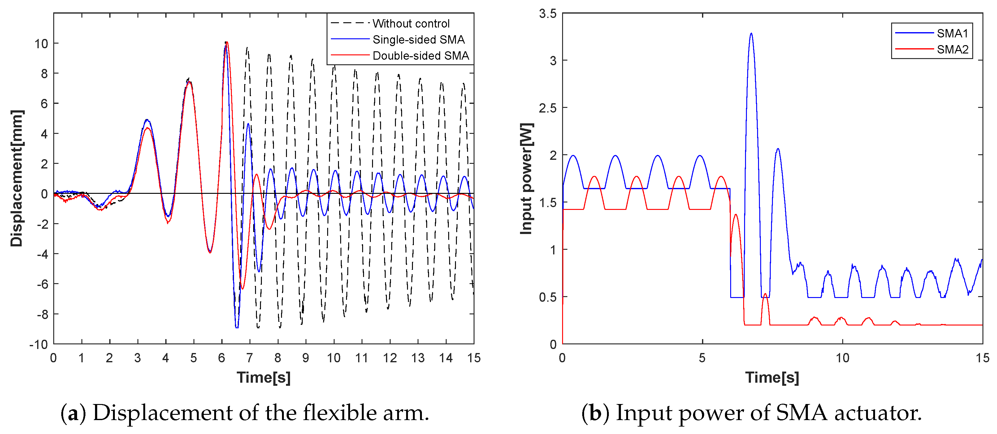
  • In experimental case 1, the operator-based nonlinear vibration controller uses a single-sided and a double-sided SMA actuator, compared with free vibration without the vibration controller. The three displacements of the flexible arm are shown in Figure 6a, where the blue line is with a single-sided actuator, the red line is with a double-sided actuator, and the black dashed line is the free vibration as a reference result. The corresponding input power for the double-sided SMA actuator is presented in Figure 6b. The results show that the double-sided interactive actuator can stabilize the vibration to almost zero within 2 s, while the vibration displacement of the one-sided actuator tends to be 2 mm. Therefore, the double-sided interactive SMA actuation for the operator-based nonlinear vibration controller is better than that with a single-sided actuator.
Figure 6. Experimental Case 1: vibration control with double-sided interactive SMA actuator.
Dynamics 03 00014 g006
  • Hysteresis compensator for vibration controller
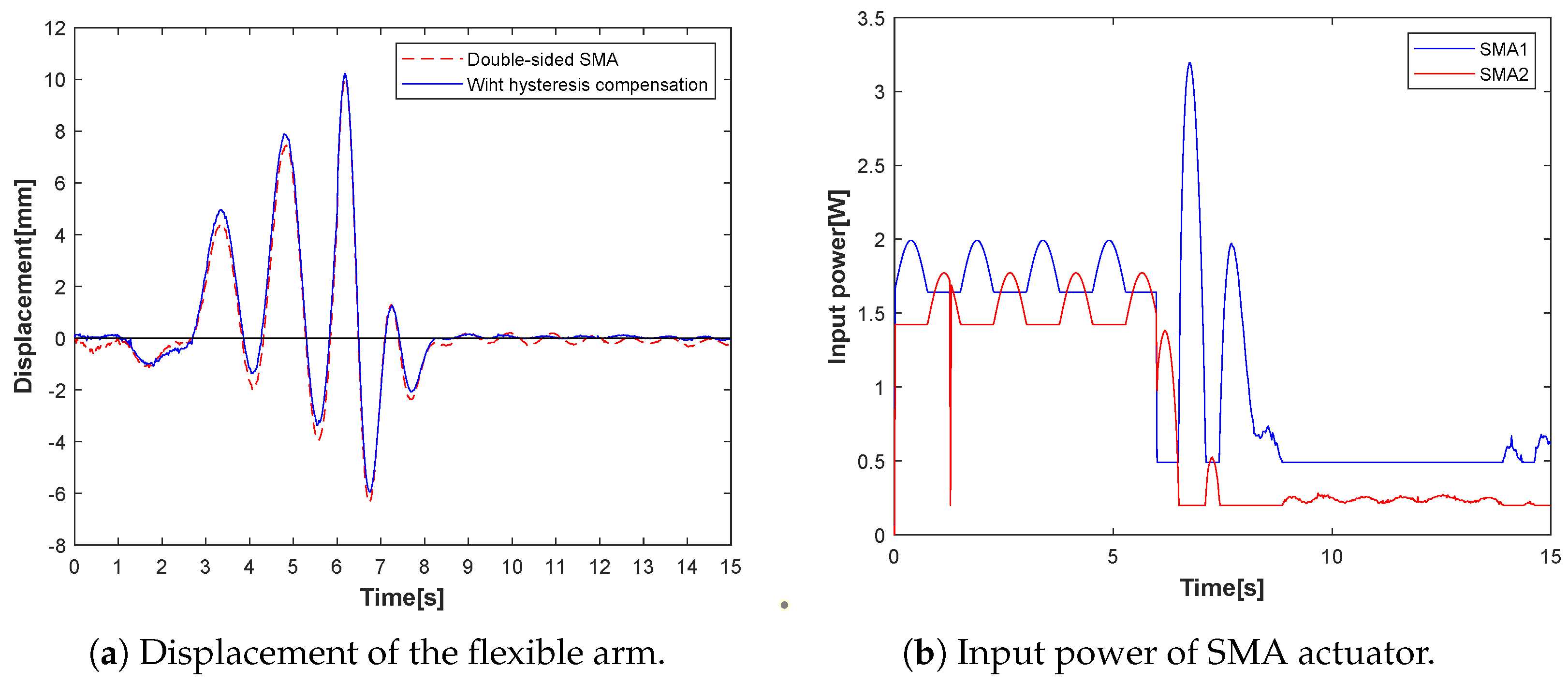
  • In experimental case 2, the effectiveness of the hysteresis compensator is compared with the vibration controller in experimental case 1. The displacements of the flexible arm are shown in Figure 7a, where the blue line is a designed hysteresis compensator, and the red dashed line is without a hysteresis compensator as a reference result. The corresponding input power for the vibration controller with compensator is presented in Figure 7b. The results show that the designed hysteresis compensator can stabilize the vibration to zero with lower input power. Hence, the advantage of an interactive vibration controller with the designed hysteresis compensator is that less energy is consumed and more precise control is obtained.
Figure 7. Experimental Case 2: vibration control with hysteresis compensator.
Dynamics 03 00014 g007
  • Fault-tolerant dynamics for vibration controller
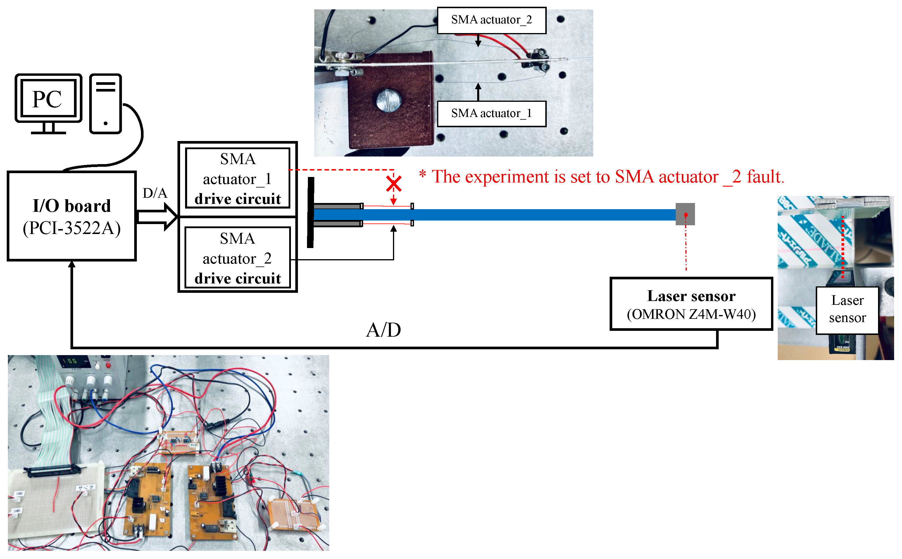
  • In experimental case 3, the fault tolerance of the system is tested with the partial actuator fault. The displacements of the flexible arm are shown in Figure 8a, where the blue line is for the faulty condition, and the red dashed line is without actuator faults as a reference result. The corresponding input power for SMA actuator_2 fault is presented at time = 7.5 s in Figure 8b. When SMA actuator_2 loses the input signal at a given moment, the proposed vibration control system remains stable by increasing the input power of SMA actuator_1. The results verify that this method has a fault-tolerant dynamic for partial actuator fault. In addition, from the view of the physical structure, using double-sided actuator hardware redundancy will better secure the system.
Figure 8. Experimental Case 3: fault-tolerant vibration control for fault actuator.
Dynamics 03 00014 g008
  • Fault-tolerant improvement for vibration controller
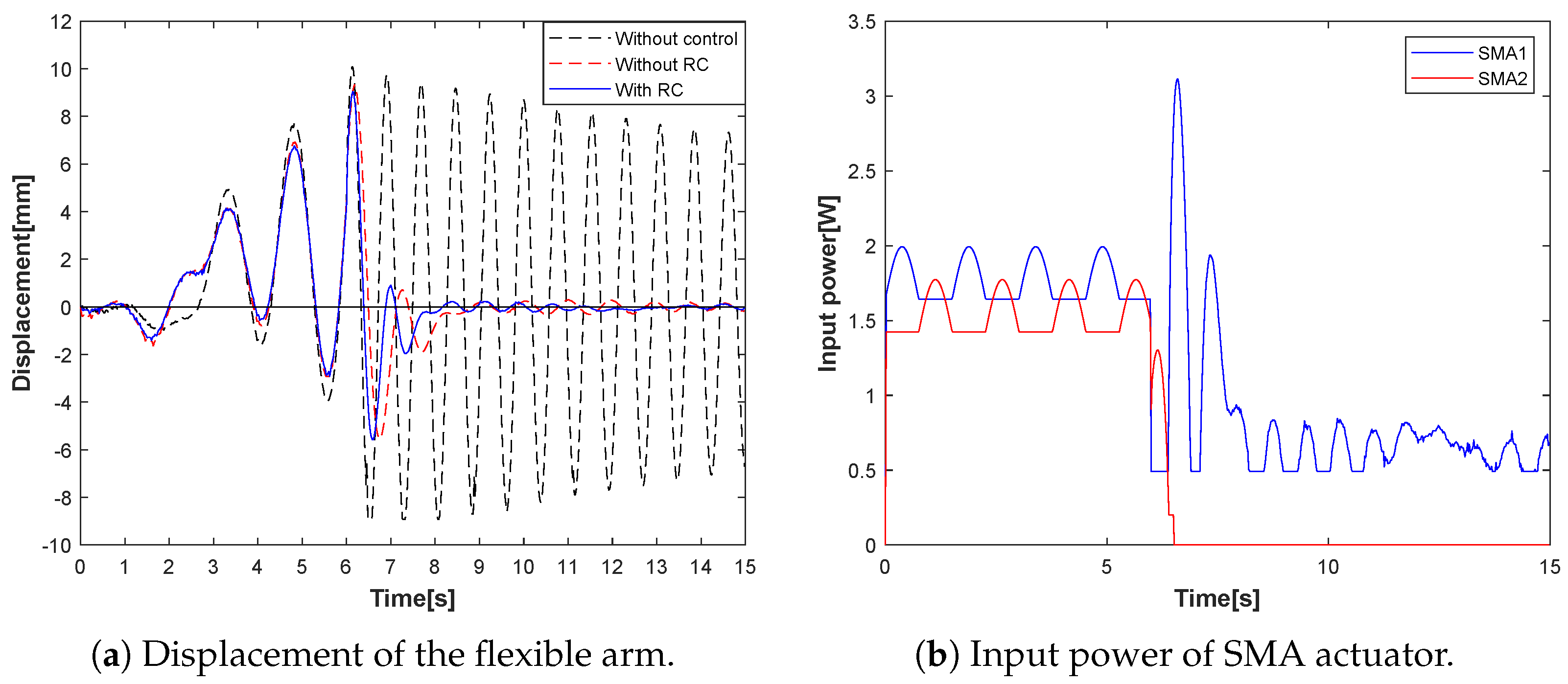
  • In experimental case 4, the fault-tolerant improvement of the system has redesigned the parameters of b 1 as a reconfigurable controller (RC). The displacements of the flexible arm are shown in Figure 9a, where the blue line is for a reconfigurable controller (RC), and the red dashed line is without RC as a reference result. The corresponding input power for RC is presented as the SMA actuator_2 is set to the actuator fault at time = 6.5 s in Figure 9b, and the proposed vibration control system switches to the redesigned b 2 . In this case, the results prove that the reconfigurable controller has improved the fault-tolerant vibration control dynamic even if it is in the presence of the fault.
Figure 9. Experimental Case 4: fault-tolerant vibration control with reconfiguration controller.
Dynamics 03 00014 g009
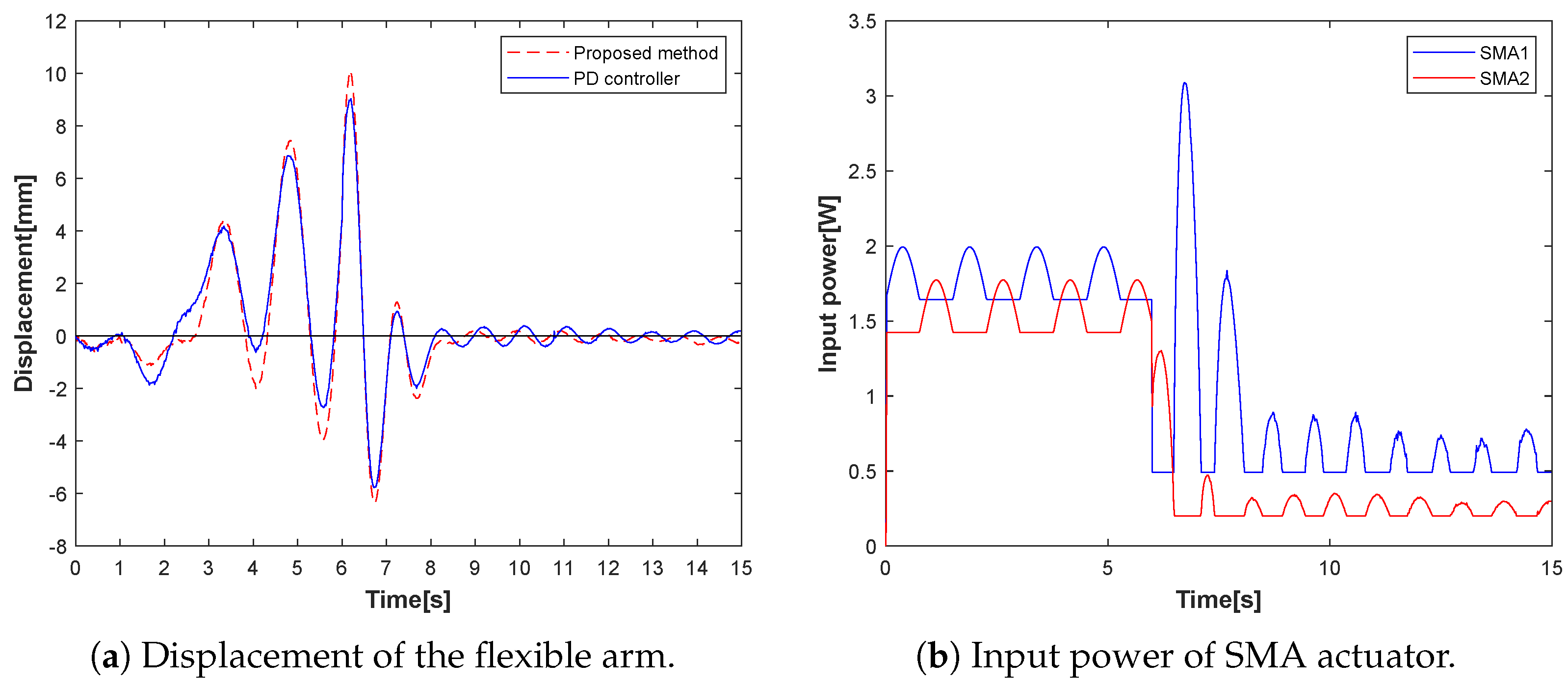
  • Traditional PD controller for vibration
  • In experimental case 5, the traditional PD controller is compared with the proposed method under normal conditions. The parameters of PD controller are found in Table 3. The displacements of the flexible arm are shown in Figure 10a, where the blue line is for the PD controller as a reference result, and the red dashed line is for the proposed method. The corresponding input power for PD controller is presented in Figure 10b. The displacement of the proposed method is smaller than PD controller with lower input power.
Figure 10. Experimental Case 5: vibration control with PD controller.
Dynamics 03 00014 g010

4.2. Discussion

The experimental tests were conducted and discussed throughout the five cases. In general, the performance indicators of the control system are good robustness, fast response, and high precision. For the vibration suppression of the flexible arm, the robust stability, tracking performance and reliability of the system, that is, the better the control system, the less time and the lower input energy consumption are required for the vibration displacement to reach zero. The vibration control using an SMA actuator with double-sided interaction achieves stability more quickly than the single-sided one in experimental case 1. The interactive SMA actuator with hysteresis compensator can reduce the vibration displacement and achieve more accurate tracking control in experimental case 2. Under normal conditions, the effectiveness of the proposed vibration control system without fault is confirmed. In experimental case 3, the proposed vibration control system was stabilized by increasing the input power, when one of the actuators occurred faulty. This case has demonstrated that the proposed method has fault tolerance dynamics for actuator faults. In experiment case 4, the fault-tolerant dynamic characteristics were improved by a reconfigurable controller for the considered faults. Finally, compared with the PD controller in experimental case 5, the proposed control system has better tracking performance and safety reliability in the case of partial actuator fault.

5. Conclusions

This paper described a fault-tolerant vibration control for a flexible arm in the case of a partial shape memory alloy (SMA) actuator having a fault. Firstly, the vibration dynamics of the flexible arm are modeled, and the thermal model and PI model of the SMA actuator are presented. Secondly, an operator-based robust nonlinear vibration control system is integrated by a double-sided interactive controller actuated by the SMA actuators, hysteresis compensator and the tracking performance of multiple feedback loops. When a single side of the SMA actuator is faulty, the proposed vibration control scheme has fault-tolerant dynamics which can still effectively reduce the vibration. The experimental cases are carried out under normal conditions and faulty conditions. From the results of the experimental case study, the vibration displacement of the flexible arm can be quickly stabilized by the proposed method. Meanwhile, the effectiveness of the fault-tolerant vibration control system is verified for partial actuator fault. The fault-tolerant improvement is achieved by switching a reconfigurable controller for a single-sided SMA actuator. In short, double-sided interactive SMA actuators not only obtain a fast response for vibration control but also tolerate the partial actuator fault as hardware redundancy. The compensator is designed for eliminating the effect of the nonlinear hysteresis behaviors from SMA actuators. The reconfigurable controller improves the fault-tolerant dynamics, while the safety and reliability of the proposed system are guaranteed even if in the presence of a partial actuator fault. Motivated by the approach of the literature [43], unified design mechanisms and module optimization are indeed popular research perspectives. Future work can consider the relationship between the shape design of arms and the vibration optimization problems of flexible arms. Mathematical modeling will also consider the finite element method to improve the accuracy of the model, which will be more helpful for the design of the vibration control system.

Author Contributions

Writing—original draft preparation, X.L.; supervision, G.J. and M.D. All authors have read and agreed to the published version of the manuscript.

Funding

This research received no external funding.

Institutional Review Board Statement

Not applicable.

Informed Consent Statement

Not applicable.

Data Availability Statement

Not applicable.

Conflicts of Interest

The authors declare no conflict of interest.

References

  1. Tabrizikahou, A.; Kuczma, M.; Łasecka-Plura, M.; Farsangi, E.N.; Noori, M.; Gardoni, P.; Li, S. Application and modelling of Shape-Memory Alloys for structural vibration control: State-of-the-art review. Constr. Build. Mater. 2022, 342, 127975. [Google Scholar] [CrossRef]
  2. Lee, S.; Jung, S. Design of a fuzzy compensator for balancing control of a one-wheel robot. Int. J. Fuzzy Log. Intell. Syst. 2016, 16, 188–196. [Google Scholar] [CrossRef]
  3. Jiang, C.; Ueno, S. Study on vibration control system of structures based on magnetic levitation technology. Eur. J. Emerg. Med. 2020, 7, 19–00307. [Google Scholar] [CrossRef]
  4. Sohn, J.; Han, Y.; Choi, S.; Lee, Y.; Han, M. Vibration and position tracking control of a flexible beam Using SMA wire actuators. JVC 2009, 15, 263–281. [Google Scholar] [CrossRef]
  5. Kadokawa, M.; Jiang, C. Development of a thin dielectric elastomer actuator with 3DOFs. In Proceedings of the 2021 International Conference on Advanced Mechatronic Systems (ICAMechS), Tokyo, Japan, 9–12 December 2021; pp. 12–15. [Google Scholar]
  6. Liu, M.; Wang, Z.; Ikeuchi, D.; Fu, J.; Wu, X. Design and simulation of a flexible bending actuator for solar sail attitude control. Aerospace 2021, 8, 372. [Google Scholar] [CrossRef]
  7. Baz, A.; Imam, K.; McCoy, J. Active vibration control of flexible beams using shape memory actuators. JSV 1990, 140, 437–456. [Google Scholar] [CrossRef]
  8. Clarke, J.; Tesfamariam, S.; Yannacopoulos, S. Smart structures using shape memory alloys. In Proceedings of the Sensors and Smart Structures Technologies for Civil, Mechanical, and Aerospace Systems 2009, SPIE, San Diego, CA, USA, 9–12 March 2009; Tomizuka, M., Ed.; International Society for Optics and Photonics: San Diego, CA, USA, 2009; Volume 7292, p. 729205. [Google Scholar]
  9. Yuse, K.; Kikushima, Y.; Xu, Y. Experimental considerations on fabrication of a smart actuator for vibration control using shape memory alloy (SMA). In Proceedings of the Smart Structures and Materials 2002: Damping and Isolation, San Diego, CA, USA, 17–21 March 2002; Agnes, G.S., Ed.; International Society for Optics and Photonics: San Diego, CA, USA, 2002; Volume 4697, pp. 382–392. [Google Scholar]
  10. Bu, N.; Liu, H.; Li, W. Robust passive tracking control for an uncertain soft actuator using robust right coprime factorization. Int. J. Robust Nonlinear Control 2021, 31, 6810–6825. [Google Scholar] [CrossRef]
  11. Amin, A.A.; Hasan, K.M. A review of fault tolerant control systems: Advancements and applications. Measurement 2019, 143, 58–68. [Google Scholar] [CrossRef]
  12. Nguyen, N.P.; Xuan Mung, N.; Hong, S.K. Actuator fault detection and fault-tolerant control for hexacopter. Sensors 2019, 19, 4721. [Google Scholar] [CrossRef]
  13. Zhao, K.; Song, J.; Ai, S.; Xu, X.; Liu, Y. Active fault-tolerant control for near-space hypersonic vehicles. Aerospace 2022, 9, 237. [Google Scholar] [CrossRef]
  14. Hagh, Y.S.; Asl, R.M.; Fekih, A.; Wu, H.; Handroos, H. Active fault-tolerant control design for actuator fault mitigation in robotic manipulators. IEEE Access 2021, 9, 47912–47929. [Google Scholar] [CrossRef]
  15. Deng, M.; Koyama, A. Operator-based robust fault tolerance control for uncertain nonlinear microreactors with coupling effects. In Proceedings of the 2019 American Control Conference (ACC), Philadelphia, PA, USA, 10–12 July 2019; pp. 3746–3751. [Google Scholar]
  16. Gao, X.; Cao, W.; Yang, Q.; Wang, H.; Wang, X.; Jin, G.; Zhang, J. Parameter optimization of control system design for uncertain wireless power transfer systems using modified genetic algorithm. CAAI Trans. Intell. Technol. 2022, 7, 582–593. [Google Scholar] [CrossRef]
  17. Ogihara, Y.; Deng, M. Operator-based nonlinear fault detection and fault tolerant control for microreactor using one-class SVM. Int. J. Adv. Mechatron. Syst. 2020, 8, 109–115. [Google Scholar] [CrossRef]
  18. Chen, W.; Jiang, J. Fault-tolerant control against stuck actuator faults. IEE Proc. Control Theory Appl. 2005, 152, 138–146. [Google Scholar] [CrossRef]
  19. Zhang, L.; Wang, Z.; Wang, L.; Zhang, Z.; Chen, X.; Meng, L. Machine learning-based real-time visible fatigue crack growth detection. Digit. Commun. Netw. 2021, 7, 551–558. [Google Scholar] [CrossRef]
  20. Furukawa, Y.; Deng, M. SVM-based fault detection for double layered tank system by considering ChangeFinder’s characteristics. Int. J. Adv. Mechatron. Syst. 2022, 9, 185–192. [Google Scholar] [CrossRef]
  21. Li, X.; Yang, G. Robust adaptive fault-tolerant control for uncertain linear systems with actuator failures. IET Control Theory Appl. 2012, 6, 1544–1551. [Google Scholar] [CrossRef]
  22. Yang, Q.; Ge, S.S.; Sun, Y. Adaptive actuator fault tolerant control for uncertain nonlinear systems with multiple actuators. Automatica 2015, 60, 92–99. [Google Scholar] [CrossRef]
  23. Qikun, S.; Bin, J.; Peng, S. Active fault-tolerant control against actuator fault and performance analysis of the effect of time delay due to fault diagnosis. Int. J. Control Autom. Syst. 2017, 15, 537–546. [Google Scholar]
  24. Theilliol, D.; Join, C.; Zhang, Y. Actuator fault tolerant control design based on a reconfigurable reference input. Int. J. Appl. Math. Comput. Sci. 2008, 18, 553–560. [Google Scholar] [CrossRef]
  25. Wang, T.; Xie, W.; Zhang, Y. Sliding mode fault tolerant control dealing with modeling uncertainties and actuator faults. ISA Trans. 2012, 51, 386–392. [Google Scholar] [CrossRef] [PubMed]
  26. Su, X.; Xiao, B. Actuator-integrated fault estimation and fault tolerant control for electric power steering system of forklift. Appl. Sci. 2021, 11, 7236. [Google Scholar] [CrossRef]
  27. Li, X.; Jin, G.; Deng, M. Nonlinear Vibration Control Experimental System Design of a Flexible Arm Using Interactive Actuations from Shape Memory Alloy. Sensors 2023, 23, 1133. [Google Scholar] [CrossRef]
  28. Deng, M.; Jiang, C.; Inoue, A.; Su, C.Y. Operator-based robust control for nonlinear systems with Prandtl–Ishlinskii hysteresis. Int. J. Syst. Sci. 2011, 42, 643–652. [Google Scholar] [CrossRef]
  29. Deng, M.; Inoue, A.; Ishikawa, K. Operator-based nonlinear feedback control design using robust right coprime factorization. IEEE Trans. Autom. Control 2006, 51, 645–648. [Google Scholar] [CrossRef]
  30. Abbaspour, A.; Mokhtari, S.; Sargolzaei, A.; Yen, K.K. A survey on active fault-tolerant control systems. Electronics 2020, 9, 1513. [Google Scholar] [CrossRef]
  31. Benosman, M.; Lum, K.Y. Passive actuators’ fault-tolerant control for affine nonlinear systems. IEEE Trans. Control Syst. Technol. 2009, 18, 152–163. [Google Scholar] [CrossRef]
  32. Lunze, J.; Richter, J. Reconfigurable fault-tolerant control: A tutorial introduction. Eur. J. Control 2008, 14, 359–386. [Google Scholar] [CrossRef]
  33. Ochi, Y.; Kanai, K. Design of restructurable flight control systems using feedback linearization. J. Guid. Control Dyn. 1991, 14, 903–911. [Google Scholar] [CrossRef]
  34. Bodson, M.; Groszkiewicz, J. Multivariable adaptive algorithms for reconfigurable flight control. IEEE Conf. Decis. Control 1994, 4, 3330–3335. [Google Scholar]
  35. Morse, W.D.; Ossman, A. Model following reconfigurable flight control system for the AFTI/F-16. J. Guid. Control Dyn. 1990, 13, 969–976. [Google Scholar] [CrossRef]
  36. Looze, D.; Weiss, J.; Eterno, J.; Barrett, N. An automatic redesign approach for restructurable control systems. IEEE Contr. Syst. Mag. 1985, 5, 16–22. [Google Scholar] [CrossRef]
  37. Wang, F.; Qian, Z.; Yan, Z.; Yuan, C.; Zhang, W. A novel resilient robot: Kinematic analysis and experimentation. IEEE Access 2020, 8, 2885–2892. [Google Scholar] [CrossRef]
  38. Gao, S.; Liu, J. Adaptive fault-tolerant boundary vibration control for a flexible aircraft wing against actuator and sensor faults. JVC 2022, 28, 1025–1034. [Google Scholar] [CrossRef]
  39. Li, L.; Liu, J. Event-triggered adaptive fault-tolerant vibration control for a flexible robotic manipulator based on the partial differential equation model. Int. J. Adapt. Control Signal Process. 2022, 36, 2083–2099. [Google Scholar] [CrossRef]
  40. Li, L.; Cao, F.; Liu, J. Adaptive vibration control for constrained moving vehicle-mounted nonlinear 3D rigid-flexible manipulator system subject to actuator failures. J. Vib. Control 2022. [Google Scholar] [CrossRef]
  41. Hasan, M.N.; Haris, M.; Qin, S. Vibration suppression and fault-tolerant attitude control for flexible spacecraft with actuator faults and malalignments. Aerosp. Sci. Technol. 2022, 120, 107290. [Google Scholar] [CrossRef]
  42. Wang, J.; Cao, F.; Liu, J. Nonlinear partial differential equation modeling and adaptive fault-tolerant vibration control of flexible rotatable manipulator in three-dimensional space. Int. J. Adapt. Control Signal Process. 2021, 35, 2138–2154. [Google Scholar] [CrossRef]
  43. Cao, L.; Dolovich, A.T.; Schwab, A.L.; Herder, J.L.; Zhang, W. Toward a unified design approach for both compliant mechanisms and rigid-body mechanisms: Module optimization. J. Mech. Des. 2015, 137, 122301. [Google Scholar] [CrossRef]
Figure 1. The load-attached flexible arm with double-sided SMA actuator.
Dynamics 03 00014 g001
Figure 3. Framework of the proposed fault-tolerant vibration control system.
Dynamics 03 00014 g003
Figure 4. Experimental setup.
Dynamics 03 00014 g004
Figure 5. The experimental setup with SMA actuator fault.
Dynamics 03 00014 g005
Table 2. Parameters of interactive SMA actuator.
DescriptionParameters [Unit]Value
Length l a [m] 0.1
Diameter d [m] 1 × 10 4
Resistance R [ Ω ] 13.5
Heat transfer coefficient h c [W/m 2   C]689
Surface area A c [m 2 ] 3.14 × 10 11
Mass m [kg] 5 × 10 6
Specific heat c p [J/kg C]7349
Table 3. Experimental parameters.
ParametersSymbol [Unit]Value
Sampling time [ s ] 0.02
Experimental time [ s ] 15
Forced vibration time [ s ] 6
Ambient temperature T 0 [ C ] 20
PD controller’s parameter k P [ ] 1.17
PD controller’s parameter k D [ ] 0.065
Designed parameter K 1 [ ] 0.0015
Disclaimer/Publisher’s Note: The statements, opinions and data contained in all publications are solely those of the individual author(s) and contributor(s) and not of MDPI and/or the editor(s). MDPI and/or the editor(s) disclaim responsibility for any injury to people or property resulting from any ideas, methods, instructions or products referred to in the content.

