1. Introduction
The transformation of the states of polarization by their interaction with a material medium exhibiting linear polarimetric behavior is determined by a 4 × 4 real matrix, called the Mueller matrix [
1] (even though it was Soleillet who described such linear transformations for the first time [
2,
3]). Mueller matrices depend on the interaction conditions, that is, given a plane light wave (probe light beam) with specific spectral profile and a material medium, different Mueller matrices characterize their polarimetric interactions depending on the relative orientation of the incident light beam and the material sample, the angle of observation (either by refraction, reflection or scattering), the area and location of the part of the sample on which the light probe falls on, etc.
Thus, once such interaction conditions are specified, the possible states of polarization of the incident light probe, which are fully described by the corresponding Stokes vectors s, are transformed as , where M is the Mueller matrix that corresponds to such a kind of interaction, and is the Stokes vector of the emerging light (in the observation direction).
Mueller polarimetry can be applied to a great collection of phenomena involving different types of electromagnetic waves. Beyond polarimeters operating in the optical range, an interesting and important case is that of synthetic aperture radar polarimetry (SAR polarimetry) where microwaves are emitted and detected from airborne or satellite devices [
4]. Since Mueller polarimeters operate in a nondestructive manner, they find an enormous variety of applications in science, industry, and medicine.
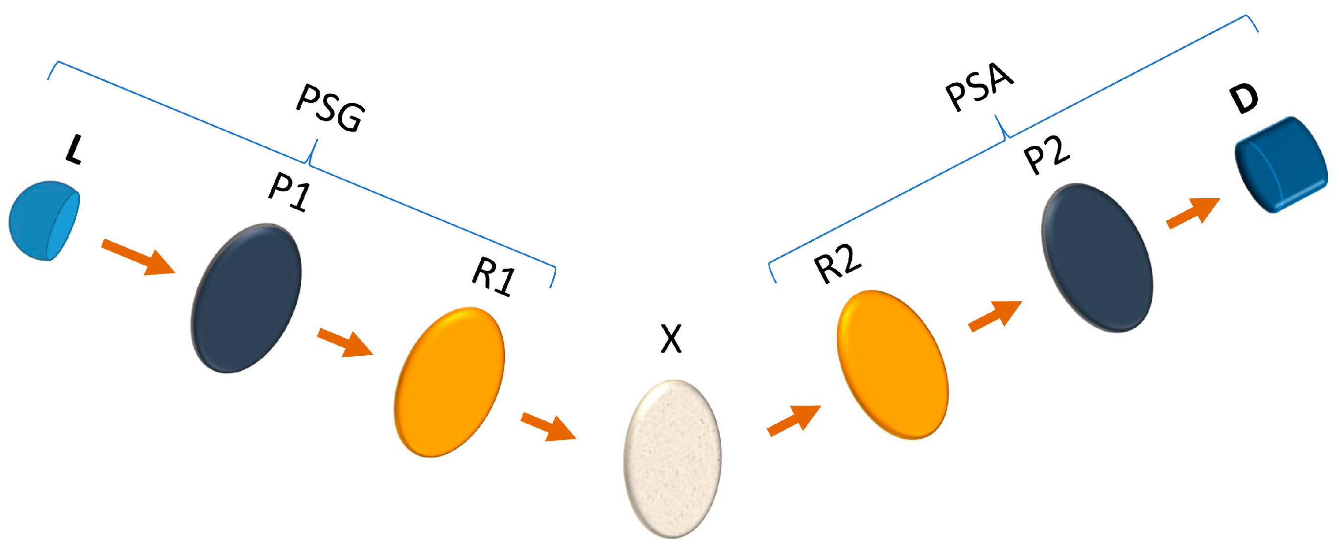
The present work is focused on Mueller polarimeters operating in the optical range and whose structure is determined by a sequence of the following elements (
Figure 1): (1) a collimated light source L; (2) a perfect polarizer P1; a linear retarder R1 (retardation plate); (3) the material sample X; (4) a second linear retarder R2; (5) a second perfect polarizer P2; and (6) a detection of light intensity and processing device D.
As shown in
Figure 1, the different elements are arranged along the propagation direction of the light probe, in such a manner that the set L, P1, and R1 constitutes the so-called polarization state generator (PSG), while the set R2, P2, and D composes the so-called polarization state analyzer (PSA). To produce a periodic intensity signal containing complete information of the Mueller matrix
M of the sample X under measurement (in general depolarizing), both linear retarders rotate with respective constant angular velocities
and
(
R being a rational number whose appropriate values will be analyzed). The unknown
M determines the shape of the periodic intensity signal and is calculated from the Fourier analysis of said signal.
Since the signal is processed through a discrete number of intensity values distributed along a single cycle of the detected signal at equal intervals, the rotation can be produced either by continuous rotation of R1 and R2 or by step-by-step motion operation.
Leaving aside possible disturbances (errors), the shape of a cycle of the intensity signal depends on the following parameters: the relative angle of the transmissions axis of P2 with respect to that of P1 (taken as the reference for the angles of the components and the sample); the relative angles and , at instant zero (taken as the origin of the cycle), of the fast axes of R1 and R2 with respect to the orientation of the transmission axis of P1; the retardances, and , of the linear retarders R1 and R2; and the ratio R (whose feasible values will be discussed from the general framework presented in this work).
Furthermore, according to certain realistic experimental configurations, the linear retarders can be considered imperfect, or non-ideal, in the sense that they exhibit respective linear diattenuations, in such a manner that they behave as diattenuating retarders [
5,
6], with respective diattenuations
and
. Obviously, there are many other physical phenomena causing depolarization and other imperfect aspects of the behavior of the retarders, which are not considered in the parameterization used in this work [
7]. The Mueller matrices associated with polarizers and retarders will be described in the next sections together with the formulation of the detected intensity signal.
Obviously, the above-indicated parameters are considered fixed (achromatic) for the whole spectral profile of the light probe, which should be narrow enough for that purpose. It should be stressed that the measured Mueller matrix corresponds to the linear polarimetric response (either depolarizing or not) of the material sample for each specific spectral profile of the light probe. In addition, different measurements can be sequentially performed for different central frequencies of the light probe, leading to spectroscopic polarimetry. Moreover, the position and relative orientation of the sample itself can be varied, producing different measured Mueller matrices. In particular, imaging polarimetry is a very fruitful technique, which is realized when the spot-size of the light probe maps a spatial area of the sample, and then different quantities derived from the Mueller matrices are represented, producing respective images.
Since the present work is focused on general features of dual-rotating retarder Mueller polarimeters, which despite being currently widely used, have a relatively long history, it is worth briefly mentioning the most notable successive contributions that have been made over time.
After a series of valuable contributions where rotating retarders were considered as components of Stokes or Mueller polarimeters [
8,
9,
10,
11,
12,
13], a first theoretical description of a dual-rotating retarder with equal ideal quarter-wave retarders (
,
) was presented by Azzam [
14]. Then, Hauge formulated the equations for a dual-rotating retarder with imperfect retarders affected by certain associated diattenuation and a ratio of angular velocities
[
15], which is the most common choice for this kind of polarimeters [
16]. Nevertheless, as discussed in further sections, other ratios can alternatively be used. It should be noted that ratios
and
(
a,
b being appropriate natural numbers) lead to entirely equivalent results, and therefore, for the sake of simplicity, without loss of generality we are using the convention
with
(i.e., the rotation of R2 is faster than that of R1).
An experimental dual-rotating retarder polarimeter was developed by Gil and Bernabéu in 1979 [
17,
18], with
, leading to fifteen independent Fourier coefficients that allow for the measurement of Mueller matrices with fewer than sixteen independent elements, as occurs, for instance, for Mueller matrices containing certain zero elements, or being symmetric, or being nondepolarizing (also called pure Mueller matrices, defined as those that do not decrease the degree of polarization of incident totally polarized light in either forward or reverse direction [
1]).
An improved complete and absolute Mueller polarimeter with imperfect retarders, self-calibration procedure, and
was then built by Gil and Bernabéu in 1983 [
19]. Many other experimental versions with
have been developed, starting with the one due to Goldstein in 1992 [
16]. A large number of similar or alternative Mueller and Stokes dynamic polarimeters, and related matters, were also reported over time [
20,
21,
22,
23,
24,
25,
26,
27,
28,
29,
30,
31,
32,
33,
34,
35,
36,
37,
38,
39,
40,
41,
42,
43,
44,
45,
46,
47,
48,
49,
50].
A number of interesting approaches for the error analysis in dual-rotating retarder Mueller polarimeters has also been published [
51,
52,
53,
54,
55,
56,
57,
58,
59,
60,
61,
62], including some relatively recent ones, which show the interest provoked by this type of polarimeter despite the time elapsed since its appearance. It is worth also mentioning the successive contributions to partial Mueller polarimetry [
63,
64,
65,
66], which is applicable to some kinds of samples, especially nondepolarizing ones.
This work deals with a general formulation of dual-rotating retarders with arbitrary configuration parameters , which is described and discussed through the following sequence of sections.
The mathematical formulations and notations used for the Mueller matrices describing the polarimetric behavior of the polarizers and retarders of the polarimeter are introduced in
Section 2.
Section 3 is devoted to the mathematical description of the Fourier coefficients of the measurement intensity signal, which can easily be determined, for instance, through computerized discrete fast Fourier transform of such a periodic signal and that allows for obtaining the elements of the Mueller matrix of the sample under measurement in terms of (1) the said Fourier coefficients and (2) the configuration parameters, including ratio
R.
Section 4 describes the self-calibration operation mode, together with the corresponding structure of the Fourier coefficients, leading to the general expressions for the effective values of the configuration parameters (for any given value of
R), as well as the overall scale coefficient introduced by the instrument, which allows for further complete measurements of the Mueller matrices of the samples (in general depolarizing), including the value of the mean intensity coefficient (absolute Mueller polarimetry), whose knowledge is critical for the physical realizability of possible serial or parallel decompositions of the measured Mueller matrices [
67,
68,
69,
70].
Leaving aside the fact that the self-calibration mode provides the effective values for the configuration parameters of the polarimeter, some advisable procedures to be realized prior the self-calibration are described in
Section 5. The self-calibration for the common and particularly interesting case where both retarders are equal is described in
Section 6.
Section 7 is devoted to the comparative analysis of the most convenient choices for the ratios of angular velocities, namely,
and
.
Section 8 deals with an example of experimental polarimeter designed with speed ratio
. Finally, the main results are summarized and briefly discussed in the Conclusions section.
2. Mueller Matrices of the Polarizers and Retarders of the Polarimeter
As described in the Introduction, the dual-rotating retarder Mueller polarimeter involves a polarization state generator (PSG) containing a fixed linear polarizer and a rotating retarder, as well as a polarization state analyzer (PSA) containing a second rotating retarder as well as a second linear polarizer.
Since polarizers with a very high extinction ratio can be easily achieved in the market [
71,
72], both polarizers of the polarimeter can be modeled through perfect linear polarizers, whose Mueller matrices have the form [
1]:
where
and
are the respective maximal intensity transmittances associated with the fast (or slow) transmission axes of P1 and P2, while
and
represent the orientations of the respective transmission axes with respect to a given laboratory reference axis
X, so that
and
are the Mueller matrices associated with P1 and P2, respectively.
Since and appear as global coefficients in the expression of the intensity signal reaching the detector, the specific vales for and do not take place in the measurement of the Mueller matrix M of the sample. Therefore, for the sake of simplicity and without loss of generality, the Mueller matrices of both polarizers will be taken with .
Regarding the retarders R1 and R2 contained in the PSG and PSA, respectively, they will be considered as non-ideal (or imperfect), in the sense that they behave as diattenuating retarders exhibiting a certain amount of diattenuation associated with the transmission of intensity for linear polarized states of light that propagate aligned to the fast and slow axes of each retarder [
5,
6,
73]. Such a behavior is realistic because of the very principle that is utilized to bring about differential retardation and, in particular, the multiple internal reflections phenomena producing certain linear diattenuation of retardation plates [
74].
The generic matrix of a linear diattenuating retarder whose fast axis is oriented at angle
φ with respect to the reference laboratory
X axis, with retardance Δ and principal transmittance coefficients
and
, has the form [
19]:
where the abbreviated notations
,
have been used for the angles appearing in the above expression, while
D and
K are the diattenuation and the counterdiattenuation [
1] of the linear retarder, respectively. As with the Mueller matrices of polarizers P1 and P2, the MICs
and
of retarders R1 and R2 can be taken to be equal to 1 without loss of generality (as we will see in
Section 4, the effective overall coefficient, or scale, affecting the intensity signal can be calculated through the calibration procedure and therefore it does not take place in the calculation of the unknown
M).
According to the usual convention in other related works, Mueller matrices normalized to have will be denoted as , so that the non-ideal retarders R1 and R2 will be represented by respective Mueller matrices denoted as , where ; are the respective angular velocities of the retarders, while are the respective angles at the time reference, .
3. Fourier Structure of the Measurement Intensity Signal
The Mueller matrix
of the serial combination of the components of the PSG (P1 and R2), the material sample (X), and the polarization devices of the PSA (R2 and P2) is given by:
where a generic ratio
between both angular velocities of the retarders has been introduced. The angular reference convention
will be taken for the subsequent calculations.
After passing through the first polarizer, P1 (with
), and regardless of the state of polarization of the light beam emerging form the light source (with associated Stokes vector denoted as
), the state of polarization of the light probe is fixed as linearly polarized oriented at
, with the associated Stokes vector:
Again, since the scale coefficient
will not take place in the final results, we will take the normalized Stokes vector
, so that the Stokes vector
s of the light probe, just before falling on the detector, is given by:
and, therefore, the detected intensity signal
is determined by the first component,
, of
s.
By using the general expressions for the Mueller matrices involved in Equation (5) as well as some trigonometric relations, the explicit form of
can be obtained as a function of the unknown elements
of
M (in general depolarizing) and the set of parameters
,
l being the overall scale coefficient to be calculated through the self-calibration process described in
Section 4.
To do so, and due to the complexity of the algebraic expressions, the abbreviated notations
,
are used for the following angles appearing in further expressions:
while the following set of auxiliary parameters is also defined:
In addition, by considering the scale
l affecting the measured intensity signal and denoting the scaled Mueller elements as
, the following set of auxiliary parameters is defined:
Then, by applying trigonometric relations and grouping terms at different frequencies, the measured intensity signal can then be expressed as:
(
R representing the speed ratio) so that the Fourier coefficients can be expressed as follows in terms of the above defined auxiliary parameters:
As indicated above, the polarimeter can equivalently operate either with
or
, and the convention
can be adopted without loss of generality. Thus, for the indices of the Fourier coefficients of the measurement intensity signal to be natural numbers (as required for the consistency of the approach presented) the speed ratio
R must satisfy the necessary condition that
is a natural number
, which ensures that the Fourier spectrum of the measurement intensity signal is composed of characteristic discrete and finite frequency lines [
14]. Equation (10) shows that the corresponding shape of the intensity signal depends on the sample, the ratio
R, and the rest of configuration parameters
, but in practice it is also affected by different types of systematic and random sources of errors (a brief comment on certain practical aspects of errors is included below).
Moreover, by accounting the number of Fourier coefficients in Equation (10), it follows that the maximal number of them (nonzero-valued) is 25 (12 harmonics in sines and cosines, plus ), while for certain values of R (for instance and ) the number of effective Fourier coefficients is smaller than 25.
In general, complete Mueller polarimetry requires that the number of nonzero Fourier coefficients exceeds 16, which is the number of independent elements of a generic depolarizing Mueller matrix to be calculated. By combining the above-indicated requirements, it is straightforward to find that the values of R should be taken from one of the series .
As described in Refs. [
17,
18], the case
is amenable to particular but consistent analysis, giving up to 15 nonzero Fourier coefficients, which in general is not sufficient for complete and absolute Mueller polarimetry of arbitrary depolarizing samples.
The calculation of the
Fourier coefficients,
N being the number of harmonics taking place in the Fourier structure of the measured intensity signal, can be performed, for instance, by means of computerized discrete fast Fourier transform (DFT). Thus, in general, a minimum number of
data points uniformly distributed along a registered cycle of the intensity signal is required to recover the complete set of Fourier coefficients. As shown in [
17], for a well-conditioned polarimeter, the use of a number of data points
, with
, does not necessarily lead to substantial improvements in the measurement accuracy.
While random errors can be strongly reduced through isolation of the polarimeter from mechanical, thermal, and optical perturbations, along with appropriate configuration of the stability of the light source and detection system, the systematic errors are usually more critical from the point of view of the accuracy of the instrument.
By inverting Equation (10), the Mueller elements
can be calculated as follows from the measured Fourier coefficients and in terms of arbitrary values for the configuration parameters
:
Note that, provided that the retardances of the rotating retarders are far enough from conditions and , the quotients in the above equations are far enough from zero (values close to constitute an appropriate choice, for instance). Moreover, due to redundancy of the available equations to isolate (25 Fourier coefficients versus 16 unknown Mueller elements ), the elements , , , , and have been calculated from two alternative expressions. Some other choices are also possible, but they do not give any advantage over Equation (11).
The above equations solve the problem of determining the elements of the Mueller matrix under measurement from the measurable Fourier coefficients of the detected intensity signal, provided the configuration parameters of the polarimeter are previously known.
Despite the fact that the configuration parameters correspond to the specific design of the polarimeter and that they are under the control of the operator of the instrument, for any given appropriate value of the speed ratio
R, the effective values for
, and
l can be measured through a self-calibration procedure described in
Section 4.
Obviously, simpler equations for the above isolated Mueller elements and for the self-calibration general procedure described in the next section, can straightforwardly be obtained for different specific values of
R and for certain particular cases as, for instance, when both retarders are equal
, or when the retarders behave as perfect
, etc. (see
Section 6).
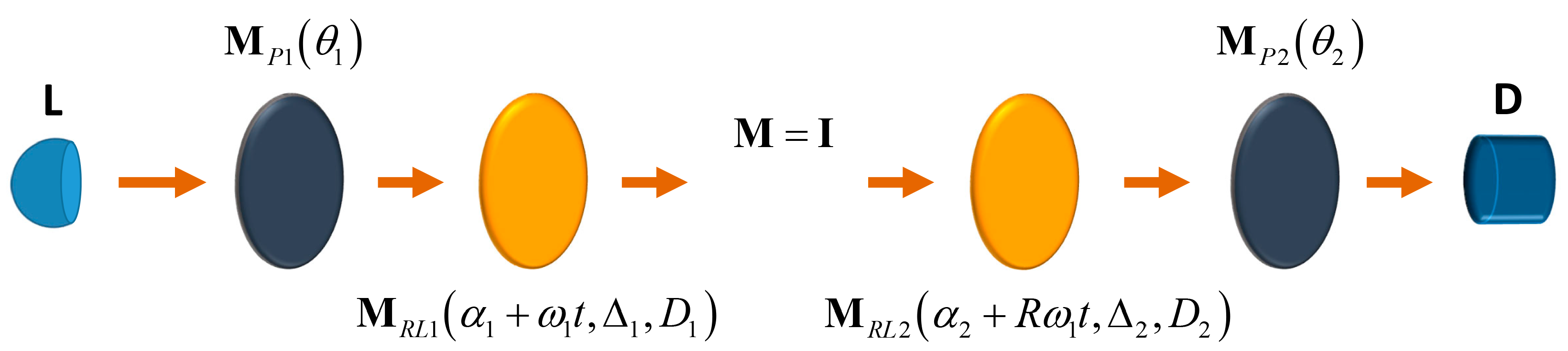
4. Self-Calibration Procedure
For any given specific value of the ratio
R, self-calibration refers to the procedure to determine the effective values of (1) the orientation angles
; (2) the scale coefficient,
l, affecting the detected and processed intensity signal, and (3) the retardances
and diattenuations
of both rotating retarders. This can easily be performed by arranging the polarimeter in direct transmission (
Figure 2) with no sample under measurement, so that then the Mueller matrix
M corresponds to the air covering the volume between both rotating retarders, which corresponds exactly to the identity matrix,
[
15,
16,
19]. Consequently, the Mueller elements
can be considered as known data in the equations describing the polarimeter intensity signal, and therefore the configuration parameters can be obtained from the Fourier analysis of the said signal.
It is remarkable that, since this procedure provides the scale parameter l, the Mueller matrices obtained through the measurement mode are determined completely, including the MIC , so that all the sixteen Mueller elements of M are measured, free of any scale factor.
Thus, in contrast to certain polarimeters that provide the normalized Mueller matrix
of the sample (with the MIC fixed at
regardless of its real value), this kind instrument is called absolute Mueller polarimeter. Note also that, beyond its intrinsic significance, the importance of the obtainment of
comes from the fact that it is critical to explore the physical realizability of serial and parallel decompositions of
M, so that certain equivalent systems should be consequently discarded because of the impossibility that they match the real parallel or serial constituents of the sample [
67,
68,
69,
70,
75,
76,
77].
The first step to formulate mathematically the self-calibration of the polarimeter is to set
in Equation (10), which leads to:
From the above algebraic expressions of the Fourier coefficients of the self-calibration intensity signal, the following set of auxiliary angles is determined:
where the numerical calculation of the ratios between Fourier coefficients is not critical because, on the one hand, the algebraic expressions of numerators and denominators are free of global factors close to zero (i.e., free of coefficients such as
or
), and, on the other hand, the denominators are far enough from zero when the initial configuration of the polarimeter (prior to the self-calibration procedure) is arranged with typical values
,
and
.
Since the parameters
and
are nonnegative, the angles
are then placed in their respective quadrants in accordance with the signs of the Fourier coefficients from which they are determined. The set of orientation angles is then obtained as:
Note that all angular parameters
in Equation (6) are determined from the above equations.
Then, for the sake of simplicity of further expressions, the following additional set of auxiliary parameters is introduced (again, free from the criticality derived from the use of Fourier coefficients affected by factors close to zero such as
or
):
so that the instrument scale coefficient is given by:
When the intensity of the calibration signal is zero, the electronic device may introduce certain signal threshold, in such a manner that a constant level, , affects the whole signal. In such a case, this constant should be subtracted from in Equation (16).
The effective diattenuations and retardances exhibited by the retarders can finally be calculated as follows:
As indicated, the above equations exclude the values
, and, to avoid critical denominators, it is advisable to use the intermediate values of
that are far from 0 and
(for instance,
). For the sake of simplicity and control of the instrument, it is also generally advisable that the orientations (at time
) of the retarders be taken so as to satisfy
and
. This is particularly easy to do through a pre-calibration method described in
Section 5.
Once the calibration has been performed, the configuration parameters can be introduced in the Expressions (11) for the elements of the measured Mueller matrix M. Obviously, it is recommended to perform the calibration procedure from time to time (to check the effective values for the angles ) and especially if the retarders are replaced. An interesting quality test can be realized by inserting into Equation (11) the values of the Fourier coefficients as well as those of obtained through the calibration, and then comparing the Mueller matrix given by Equation (11) to the identity matrix. The distance between both matrices (experimental and theoretical) can be calculated, for instance, as the Frobenius norm , which provides an appropriate overall measure of the precision of the instrument.
5. Pre-Calibration Procedures
Leaving aside the fact that the self-calibration provides the effective values for the configuration parameters of the instrument, it is obviously advisable an appropriate (at least approximate) previous adjustment of the orientation angles as well as the independent measurement of the diattenuations and .
The determination of and can be performed through the following steps:
Taking the orientation angle of P1 as the angular reference , remove both retarders and rotate P2 until the intensity reaching the detector is closest to zero (provided a proper arrangement of the polarizers, orthogonal to the direction of the light probe, the extinction coefficient should be extremely low).
Insert R1 and rotate it until the extinction arranged in the previous step is preserved. This ensures that either the fast or the slow axis of R1 is aligned to the transmission axis of P1, i.e., .
Rotate P2 and put it at .
Measure the intensity, , reaching the detector.
Apply a rotation of to R1.
Measure the intensity, , reaching the detector.
In accordance to the expressions for the transmittances associated with the fast and slow axes of waveplates (see Equations 3.1 and 3.2 of Ref. [
74],), if
the fast axis of R1 is now oriented at
with respect to
. Otherwise
, R1 is actually aligned to
.
Calculate by means of , where , with and .
Apply to the second retarder, R2, the procedure described above, so that the orientations of the fast axes of R1 and R2 as well as their diattenuations have been determined.
Despite the fact that, for ideal or high-quality retardation plates, the equality is satisfied with good approximation, in general the measurement of can also be easily realized by analyzing the extremal values of the intensity signal obtained though continuous rotation of R1 (R2).
Once the polarimetric behaviors of R1 and R2 (for the given central frequency and bandwidth of the light probe used) have been determined, the polarimeter can be arranged through a procedure such as, for instance:
Taking the orientation angle of P1 as the angular reference , remove both retarders and rotate P2 until the intensity reaching the detector is minimal (zero), i.e., .
Insert R1 with its fast axis oriented approximately at ; then slightly rotate it until the extinction of the intensity signal is preserved, so that .
Insert R2 with its fast axis oriented approximately at ; then slightly rotate it until the extinction of the intensity signal is preserved, so that .
Rotate P2 and put it at . Thus, the orientations arranged ensure the stability of the equations for both the self-calibration and Mueller measurement operation modes.
Another important aspect regarding the pre-calibration stage is that small tilts of the planes containing the retardation plates, producing undesirable lack of perpendicularity with respect to the direction of propagation of the collimated light probe beam [
60] lead to slight differences between consecutive cycles of the self-calibration intensity signal. Therefore, the analysis of such possible differences is useful to identify the indicated source of systematic errors and to address the corresponding adjustments in the polarimeter in order to optimize its accuracy.
6. Self-Calibration of a Polarimeter with Equal Retarders
Since it is in general advisable to use retarders whose effective retardance for the light probe is not far from
(with achromatic behavior for the entire spectrum of the light probe), and there is no advantage of using different retarders, a common and natural choice is to take equal retarders (in general non-ideal), in which case the Fourier coefficients take the forms:
Equations (13)–(17) become redundant, which does not prevent their use for the self-calibration. Moreover, the Mueller elements of the material sample (measurement mode) are given by Equation (11), but applying the equalities:
For certain theoretical comparisons and analyses, it is useful to have at hand the simple mathematical expressions corresponding to the limiting case where both retarders behave as perfect quarter-wave retarders, i.e.,
with
. Then,
so that the Fourier coefficients take the simplified forms:
while the effective orientations
can be calculated through Equations (13) and (14).
If, in addition,
,
. Then,
and consequently,
7. Polarimeters with and . Comparative Analysis
The number of nonzero Fourier coefficients of the measurement intensity signal
in Equation (9) (for arbitrary Mueller matrices under measurement) depends on the ratio
of the angular velocities of the retarders R2 and R1. In particular, the choice
provides fifteen nonzero Fourier coefficients, which are sufficient to retrieve the Mueller matrix of a nondepolarizing sample [
17,
18] (nine independent parameters) or certain specific kinds of samples (those having symmetric Mueller matrices, for instance), but are insufficient to obtain the sixteen independent elements of the Mueller matrix of an arbitrary depolarizing sample under measurement. Thus, values such as
or
(with the convention taken
) are required for a general complete Mueller polarimetry, in which case the number of Fourier coefficients exceeds 16, and some redundancy of information is produced (which does not imply any practical problem).
Moreover, the use of different retarders for R1 and R2 is not worth it, in general, and therefore retarders with equal nominal retardance are commonly adopted for the configuration of the polarimeter.
Prior to the analyses of the cycles of the intensity signals for different values of R, it should be recalled that a rotation of an angle of a retarder leaves its Mueller matrix unchanged.
The particular choices require special attention because they are the lower values leading to complete Mueller polarimetry. Regarding the speed of the measurements, both ratios can be considered equivalent because the period of the intensity signal is determined by two and half turns of R2 regardless of whether or , so that the cycle involves a half turn of R1 when , or a full turn of R1 when . Thus, the period of a cycle is in both cases .
As for the self-calibration signals, the expressions for the Fourier coefficients for and are shown below (equal retarders are considered in both cases).
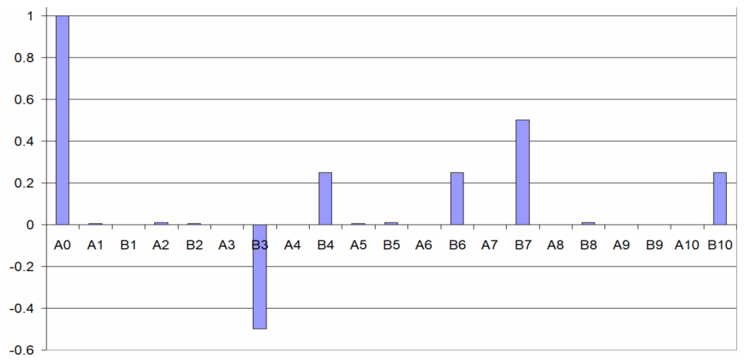
Fourier coefficients for the calibration signal with :
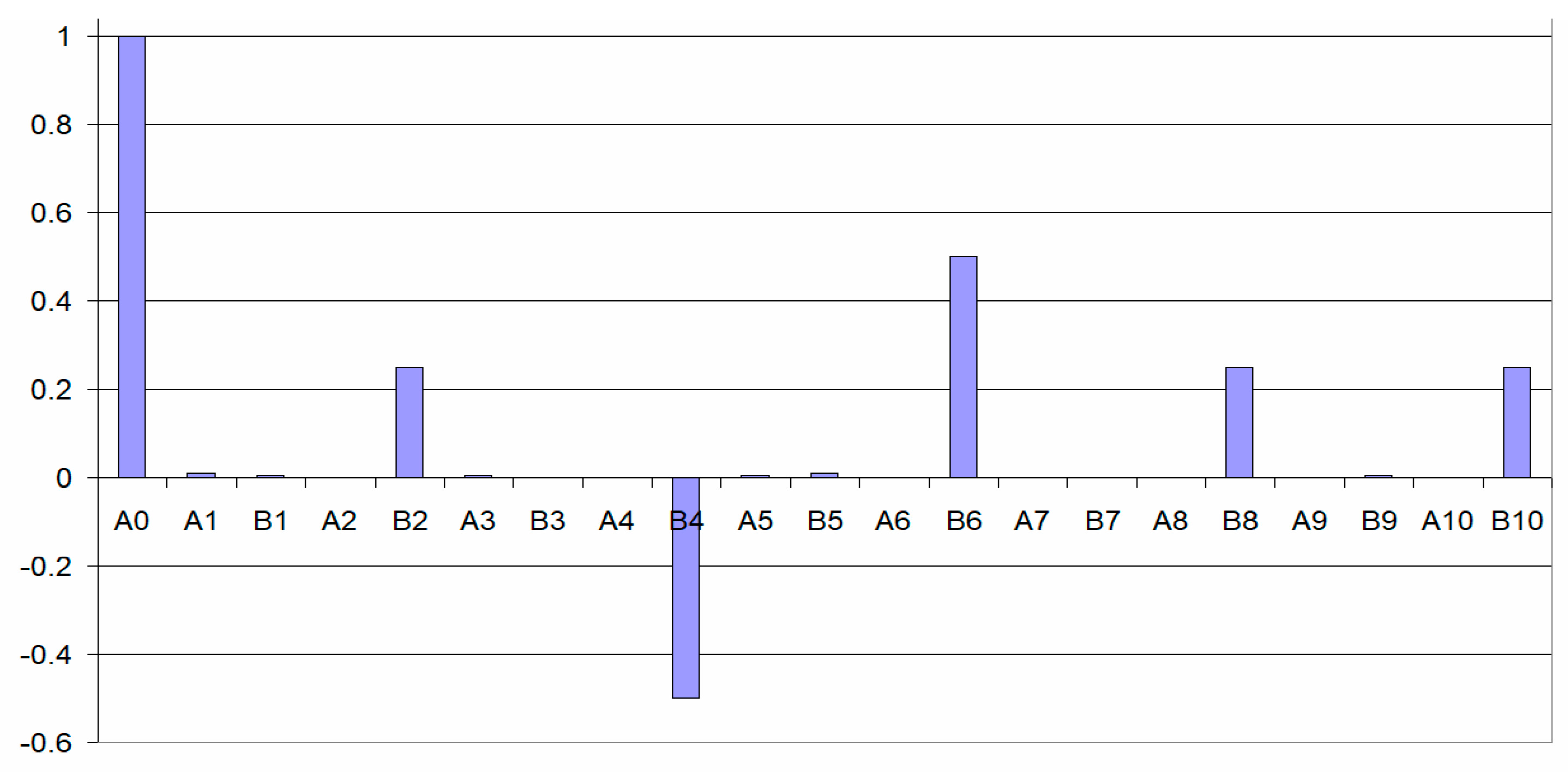
Fourier coefficients for the calibration signal with :
As indicated above, a complete measurement cycle is produced through a rotation from to of R2, which corresponds to a half turn of R1, (from to when ), or a full turn (from to when ). As a consequence, the odd Fourier coefficients of the calibration signal corresponding to are zero, and the replacement of by allows for re-labeling the indexes of the nonzero Fourier coefficients, which then run until 10 instead of 20.
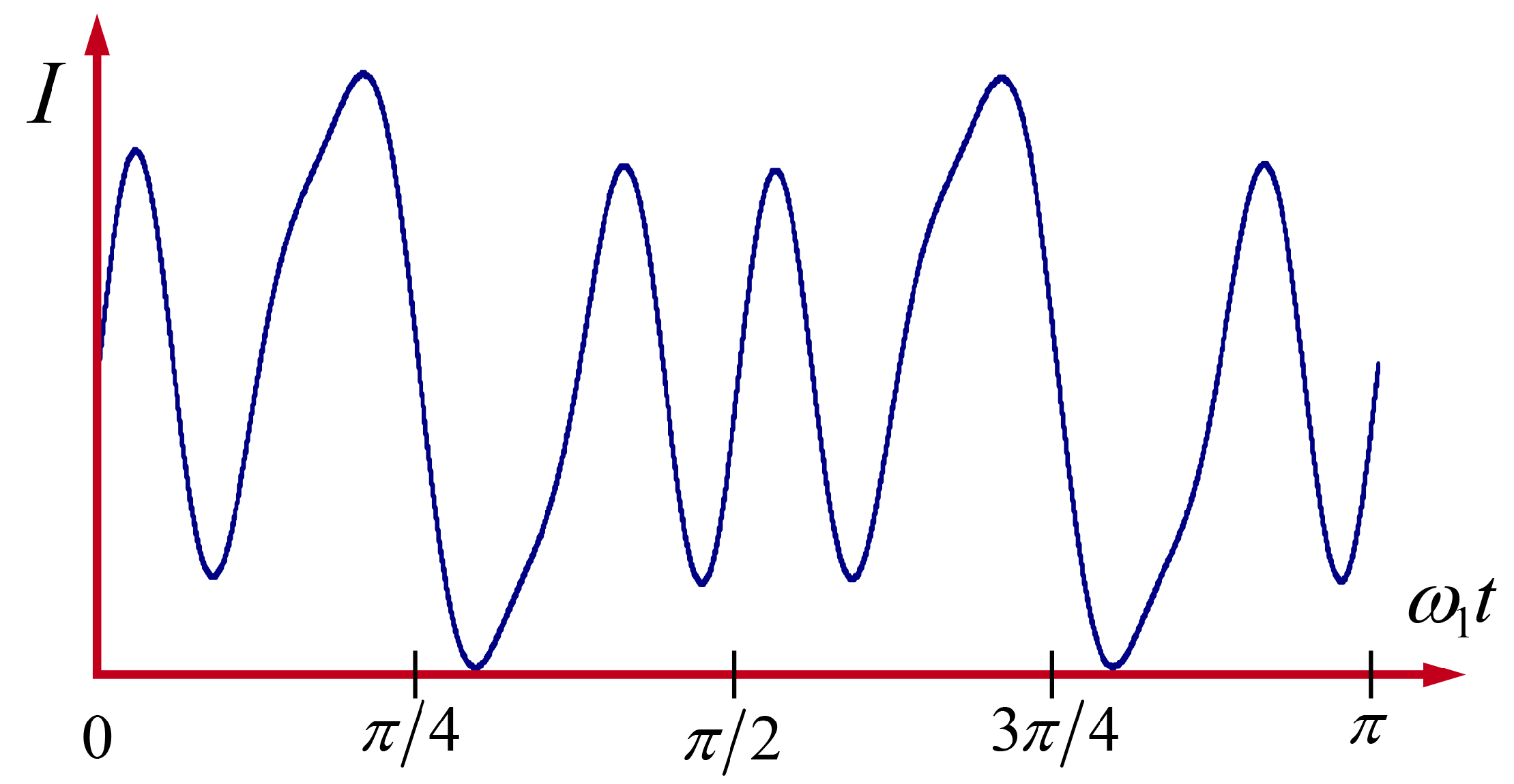
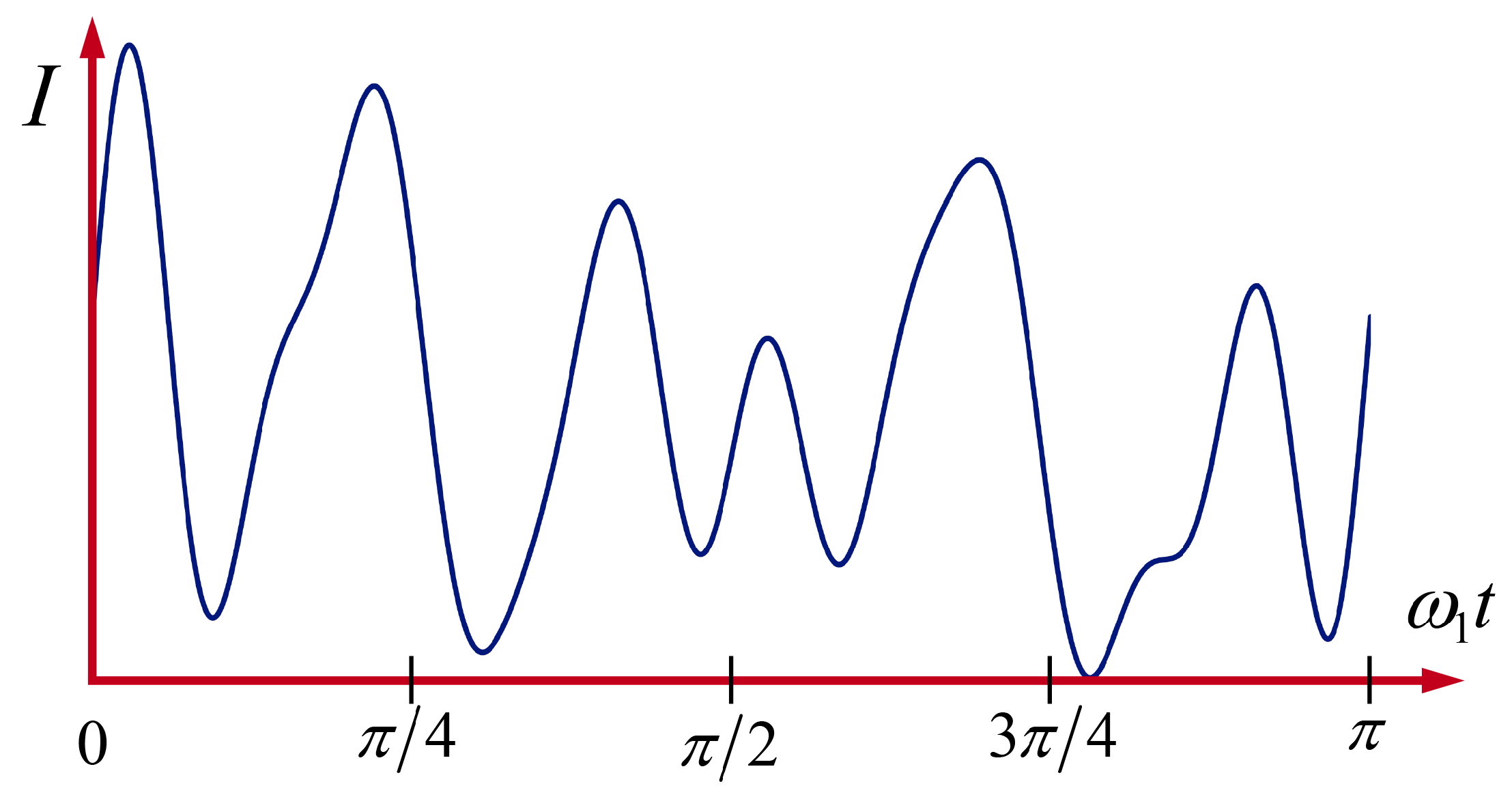
To illustrate the peculiarities and differences between the polarimeters configured with
and
, the respective shapes of simulated single cycles of the calibration signals are represented in
Figure 3 and
Figure 4.
It is remarkable that, contrary to what happens for
, when
the shape of an entire cycle of the calibration signal
exhibits two semi-cycles whose slight difference depends exclusively on the value of the small diattenuation
D of the equal retarders R1 and R2. In fact, when
, such a double periodicity is exact, while, as shown in
Figure 5, for relatively large values of
D the calibration signal is far from such an apparent double periodicity. This peculiar behavior of the calibration signal for
suggests certain criticality of the calibration process that is not featured in the case
.
A complementary and useful view of the above self-calibration signals is provided by their respective Fourier structures, i.e., the representation of the relative values of the Fourier coefficients involved.
In both cases under analysis (
, in
Figure 6, and
, in
Figure 7) a number of 13 nonzero Fourier coefficients arise, six of them being significant (far from zero). Coefficients
(when
) and
(when
) are close to zero due to the small value of the diattenuation
D of the retarders, and they become zero for the ideal case when
. In accordance to the calibration algebraic expressions in Equations (13)–(16), such spectra are sufficient to calculate consistently the entire set of configuration parameters
.
The general Equation (11), giving the elements of the Mueller matrix M of the sample under measurement, adopts the forms shown below when and , respectively, where the simple and practical condition that both retarders are equal is assumed ( and ).
Mueller elements for a polarimeter with
and equal retarders (the labels of the Fourier coefficients correspond to multiples of the angular frequency
):
Mueller elements for a polarimeter with
and equal retarders (the labels of the Fourier coefficients correspond to multiples of the angular frequency
instead of
):
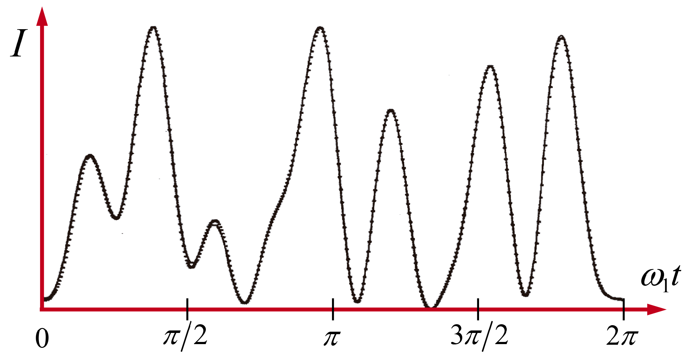
8. An Experimental Example of Absolute Mueller Polarimeter with
Since dual-rotation retarder Mueller polarimeters are usually realized with
, it is worth to briefly describe experimental results obtained through the less common choice
.
Figure 8 reproduces an example of the experimental calibration signal of the polarimeter designed by Gil and Bernabéu [
19] and its comparison to the ideal signal corresponding to the measured configuration parameters.
Even though both retarders and polarizers used where made from simple commercial Polaroid sheets, while the optical benches and other mechanical systems were somewhat rudimentary, the theory-experiment adjustment was really good, which stresses the suitability of the choice and the use of non-ideal retarders.
As described in Ref. [
19], each of the retarders R1 and R2 were synthesized from respective serial combinations of two commercial waveplates [
78] whose relative angles were fitted to get
(note that the effects of both, mutually inverse, extra rotators of such combinations were directly compensated leading to a neutral overall effect in the calibration signal and an apparent rotation of the sample in the measurement mode operation).
Many experimental results as well as technical details of this experimental setup can be found in Refs. [
17,
18,
19], including the continuous mode operation of the rotation of the retarders; the light source; the calculation of the Fourier coefficients from the detected intensity signal through a DFT algorithm based on standard procedures [
79]; etc.
9. Conclusions
A general formulation for dual-rotating retarder absolute Mueller polarimeters with imperfect retarders and arbitrary ratio of angular velocities of the retarders has been developed, including explicit expressions for the Fourier coefficients of the cyclic measurement intensity signal as well as for the elements of the Mueller matrix of the sample under measurement (in general depolarizing).
The self-calibration mode, based on direct transmission without sample, allowing for the measurement of the effective configuration parameters of the polarimeter, namely the retardances, diattenuations, and angles (at time zero) of both retarders; the angle of the transmission axis of the second polarizer; and the scale coefficient introduced by the detection and processing subsystem, is described for arbitrary values of the ratio between the angular velocities of the rotating retarders.
The said calculation of the scale coefficient is a requirement for the absolute measurements of the Mueller matrices of the samples; that is, instead of a normalized Mueller matrix, all the sixteen Mueller elements, including the mean intensity coefficient (i.e., the mean transmittance or reflectance) are determined. The absolute measurements are important because they provide criteria to check the physical realizability of serial or parallel combinations of simple and passive components whose overall polarimetric behavior is equivalent to that of the sample.
Some pre-calibration procedures have also been described, including the comparison of pairs of consecutive calibration cycles as a way to check the perpendicularity of the retardation plates with respect to the axis defined by the collimated light probe.
A comparative analysis of polarimeters working with the smaller ratios (5/2 and 5/1) compatible with the measurement of the complete Mueller matrix of the sample has been performed. A peculiarity of the ratio 5/1 is that, contrary to what happens for 5/2, a single cycle of the calibration intensity signal contains two semi-cycles whose difference depends exclusively on the diattenuations exhibited by the retarders.
Expressions for the most common case where both retarders exhibit equal retardances and diattenuations, as well as some examples for the calibration signals obtained in different configurations, are also included.
In summary, since rotating retarders are extensively used as the functioning principle of many Mueller polarimeters, the results presented in this work provide a deeper insight for the better configuration and use of dual-rotating retarder absolute Mueller polarimeters.


