1. Introduction
Pressure on the European manufacturing industry is increasing due to growing competition worldwide. Therefore, companies need to develop new business models and more flexible processes through initiatives such as Industry 4.0 by connecting operating infrastructure in order to produce variant-rich products faster and at lower costs. This need is leading to steady advances in automation of production technology. In particular, the prevailing shortage of skilled workers is leading to an increase in automation within Europe [
1]. This same shortage is affecting production metrology. In the current trend, classic measuring labs are being replaced by process-integrated inspections for quality assurance [
2]. This enables higher flexibility and automation in manufacturing processes. Measurement technology integrated into the process enables automated measurement independent of quality inspection capacities as well as flexible production processes that can be dynamically controlled depending on the measured results.
In addition to form and position tolerances, surface roughness plays a significant role in structural components’ functional surfaces [
3,
4]. Increasing attention is paid to technical surface quality, particularly in medical technology, biotechnology, process engineering, automotive, and aviation [
5]. In the past, only a few characteristic values were measured (i.e., Ra and Rz), which provided little information about the surface quality for technical purposes [
6]. In recent years, many parameters have been developed that describe the functional surfaces for different purposes in great detail [
7]. Today, continuous monitoring and display of surface finishes are usually only possible for the outside of machine tools, resulting in loss of quality and time or meaning that processing has to be interrupted for manual roughness measurement.
There are both 3D (primarily optical) and 2D (often tactile) methods for measuring surface roughness. Different optical methods are often not comparable due to the different types of data acquisition used [
8]. For this reason, tactile measurement is often the reference, as it is defined in standards and as such is highly reproducible [
9,
10]. Gao et al. [
11] have provided a good overview of the state of the art in this field of research.
Several systems for integrated roughness measurement on CMMs are known and available on the market [
12,
13]. However, these two systems cannot be used with machine tools due to their fragile construction and the harsh environments in which machine tools are used. Until now, there has been only one system for integrated roughness measurement of machine tools on the market, which was developed by the Blum company [
14]. It works similarly to a touch probe for machine tools, and uses the feed of the machine tool to slide a probe head over the surface. Due to the inaccuracy of the machine beds and the fact that a defect in the machine axis cannot be detected because it is used twice, it cannot be used to make measurements that conform to standards. The manufacturer states that only roughness Rz > 2 μm can be measured.
The possibility of integrating tactile roughness measurement within machine tools for integrated measurement was investigated in a research project within the German Mahr company. A prototype resulting from this project has already been developed. In this article, the developments to date are described, along with potential usage scenarios of integrated roughness measurement. The project aims to develop a fully integrated roughness measurement system for machine tools, which should enable fully standardized measurements in an automated manner. Initial tests have shown that it is possible to obtain measurements in the range of Rz > 0.04 μm (on an optical flat) in a reasonable manner.
2. Materials and Methods
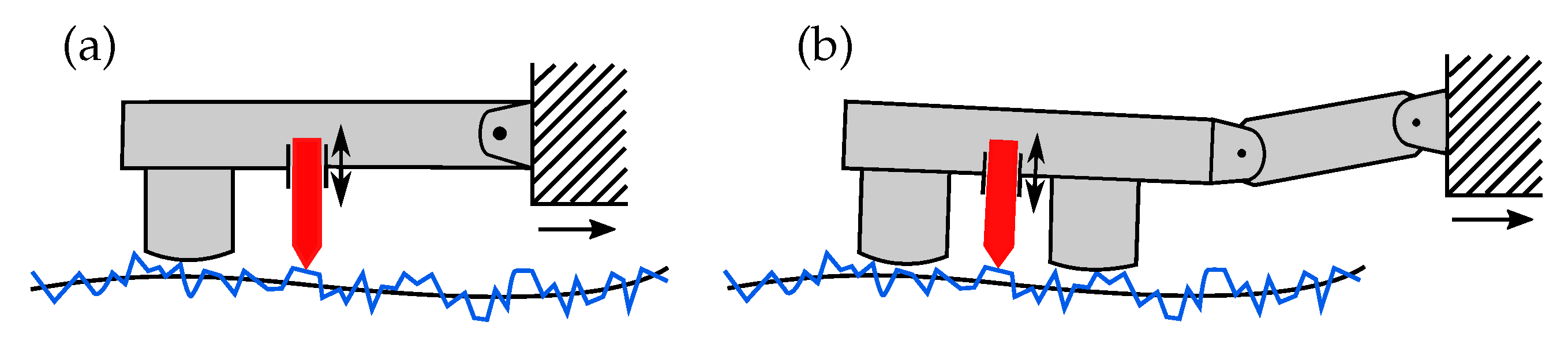
As already described, a differentiation has to be made between optical and tactile roughness measurement systems. The tactile variant was selected, as the system should enable fully standard-compliant measurement. Another distinction is made between skidded probe systems and skidless systems [
15]. The following
Figure 1 and
Figure 2 show the two technologies.
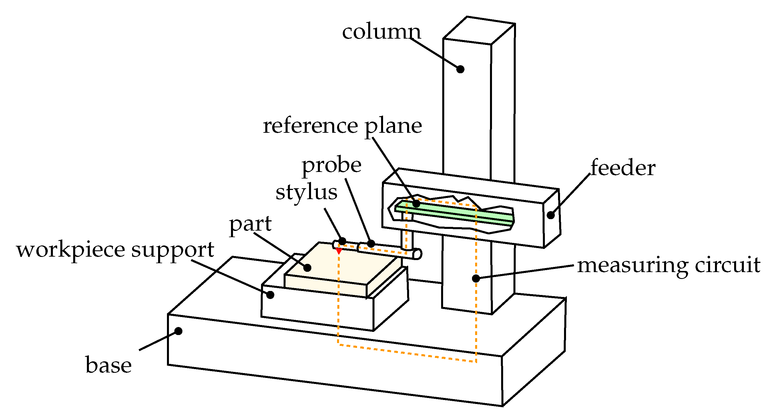
Skidded probe systems use the workpiece surface as a reference and glide over the surface with skids. There are single- and double-skidded versions. A stylus is moved over the surface, a sensor records its displacement, and the data are stored as a primary profile. This technology can be designed in a very compact form and is insensitive to vibrations. Waviness is mechanically filtered away by sliding over the surface; thus, it cannot be measured. Skidless systems have a reference surface built into the measuring device that is compared with the workpiece surface. This type of measurement allows for exact measurements, and represents the standard-compliant reference for surface roughness. Form deviations and waviness can be measured with this design. Such systems are usually only used in laboratory environments in order to ensure the appropriate framework conditions. One disadvantage results from the large measurement circuit, which reacts sensitively to vibrations and oscillations. Usually, high-frequency errors occur, which can be compensated for to a certain extent [
7,
16]. However, as low-frequency vibrations can occur in the machine tools being measured, the described compensation methods can only be applied to a very limited degree [
17], meaning that the measurement circuit in the machine tool has to be significantly reduced in order to generate plausible measurement data. This issue is demonstrated and confirmed in the preliminary tests described below.
2.1. Preliminary Tests
At the beginning of the project, preliminary tests were carried out to evaluate both tactile measurement technologies in the work area of a machine tool (skidded and skidless). Roughness measuring devices already available on the market were mounted on tool holders with 3D-printed adapters, and initial measurements were carried out on roughness standards and on an optical flat. In this way, it was possible to analyze the influences of the machine tool and its environment in detail.
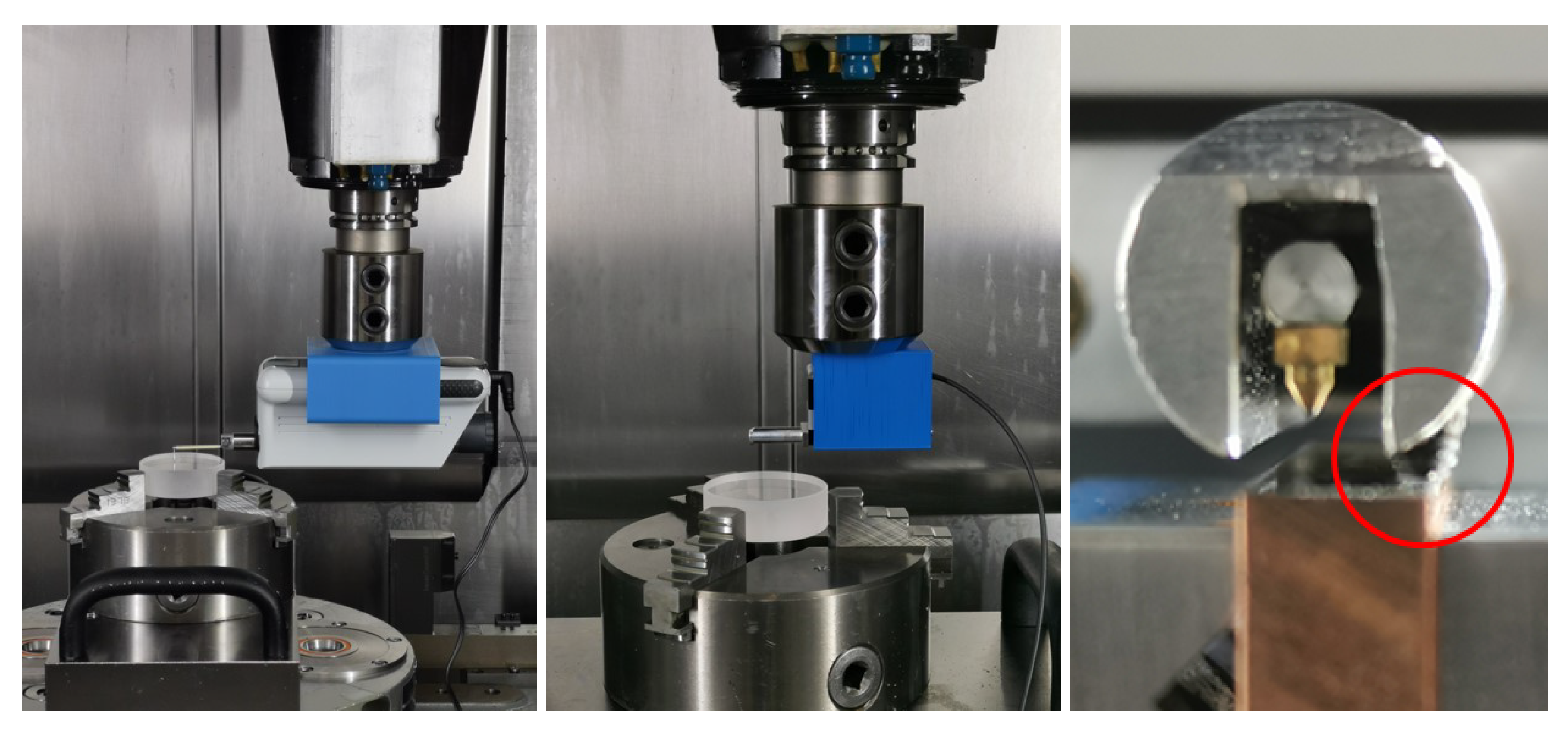
Figure 3 shows the first test setups of skidless probing systems. A Mahr skidded probe (M310), not shown in
Figure 3, was tested as well. The advantage of the skid system is that it is insensitive to vibrations; however, it does not allow for standard-compliant measurement.
Because using a skidless touch probe was preferable, the focus was placed on this type of device at the beginning. On the one hand, the SD26 from Mahr was used (see
Figure 3 left), which is a classic skidless probing system [
18]. It enables standard-compliant measurements, although unfortunately it requires a lot of installation space. On the other hand, the MiniProfiler from Breitmeier uses an adjusting screw to support itself on the workpiece surface via the probe arm housing (see
Figure 3 middle and right) [
19]. The red circle in
Figure 3 shows the support on the workpiece. The contact between the measuring device and the workpiece is a rigid coupling, which massively reduces the size of the measuring circle and consequently the influence of vibrations and oscillations. It is the smallest skidless system currently available on the market. Tests were carried out with rubber damping elements as well, finding that soft elements lead to worse results. The probe tip is lifted up automatically when not measuring. Measurement is fully compliant with the standard. For comparison purposes, measurements were carried out on roughness standards and an optical flat, and massive differences were found. For example, a result of Rz = 0.412 μm was obtained on the flat glass with the SD26, while a result of 0.036 μm was obtained with the MiniProfiler. This behavior was reproducible over the course of several measurements. With a roughness standard of Rz = 3 μm, a deviation of less than 10% could be determined almost continuously with the MiniProfiler, it is clear that if a skidless system is to be used, support of the measuring device on the workpiece surface is necessary for plausible measurement of the roughness within the machine tool. As the results were satisfactory, the use of the MiniProfiler as a basis for development was determined.
2.2. Conceptual Development
Based on the preliminary tests, a concept for a roughness-measuring device integrated into machine tools was developed. Together with Mahr, the primary conditions that the device should finally fulfill were defined. An important point here is the storage possibility in the tool changer of a CNC machine and the possibility of changing the device from this into the spindle in a fully automatic fashion. Another requirement was wireless operation, consisting of an integrated energy supply via rechargeable battery and communication via Bluetooth. In order to ensure that the operating time until the following charging cycle was as long as possible, a feature for switching between standby and operation via Bluetooth was defined. Data exchange via OPC UA, a manufacturer-independent Ethernet-based industrial protocol supported by many modern controls, ensures universal usability on all types of machines and controls. In order to be able to measure boreholes on the one hand and to reach as many measuring points as possible on the other, the optional integration of rotary and swiveling joints in the measuring device was specified.
The swivel function should be used for defined contact with the workpiece surface by integrating a force sensor into the supporting structure. Another critical point was the possibility of automatically cleaning the workpiece surface at the measuring point to enable the removal of chips and coolants before the measurement. With these requirements, a concept based on the technology of the MiniProfiler was developed and then prototypically implemented. This system has a measurement uncertainty of 0.5% and a measurement range up to 2 mm. The maximum distance for measurement is 15 mm, whereby the travel speed reaches from 0.1–2 mm/s. The aim of the project is to develop a functional prototype for in-process roughness measurement. It is necessary to investigate whether a fully compliant measurement in the machine tool is achievable. Based on the results, a production-ready product will be developed at a later stage.
2.3. Development of a Prototype
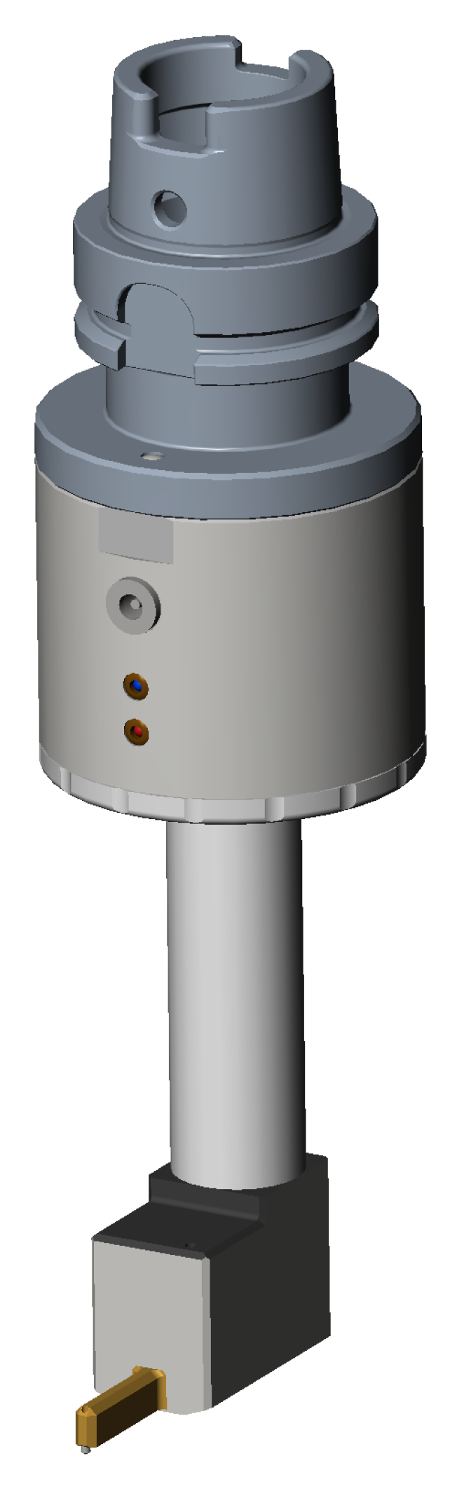
With the requirements defined, a CAD model was designed for an integrated roughness-measuring device (see
Figure 4). The device was designed in such a way that it can be equipped with different tool holder adapters made of steel depending on the intended use. These adapters ensure that one device can be used in different machines with different tool holders.
The housing of the measuring device was made of aluminum to ensure that it is both lightweight and robust against chips and cooling lubricant. In the first iteration, it was decided to wait to integrate a rotary and swivel axis in order to keep the complexity low and to be able to perform initial tests quickly in a machine tool. In the process, complete subroutines for machine controllers (Fanuc, Siemens, Heidenhain) were programmed, which made it possible to carry out measurements without specialist knowledge of production metrology. All that is necessary is to enter the desired measuring position as a parameter. After calling up the corresponding program, all necessary steps are carried out fully automatically.
The measurement sequence in the machine workspace was defined as follows:
- 1.
CNC calls roughness measurement
- 2.
Tool change to measurement tool
- 3.
Positioning of the device on the workpiece
- 4.
Send wake-up and start commands
- 5.
Wait until measurement is completed
- 6.
Transmit measured profile and calculate desired values
- 7.
Transmit values to the CNC controller via OPC UA
- 8.
Bring measuring devices back to the tool changer
- 9.
React to measurement (OK/NOK/REWORK)
3. Results
In the following section, the results of the measurements with the developed prototype are explained and considered in detail.
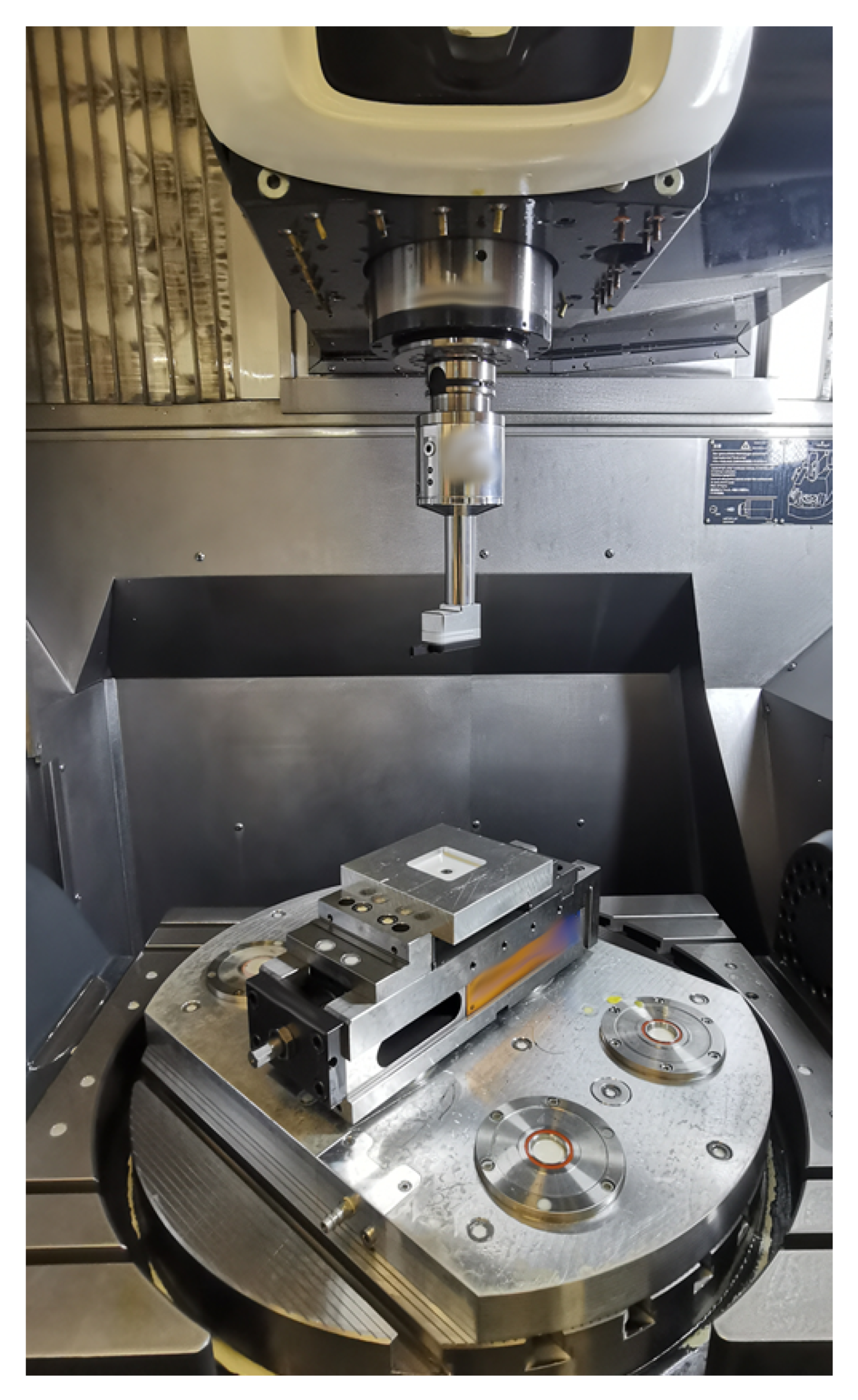
Figure 5 shows the prototype of the measuring device in a DMU 75 monoBlock from DMG Mori, which is equipped with a FANUC control.
3.1. Mechanical Endurance Tests
The pick-up of the tool from the tool magazine in a machining center causes high stress on the measuring device, as it contains many small parts and sensitive electronics. Thus, the measuring device is subjected to an acceleration of approximately 5 m/s² with every change. In order to test the mechanical durability and the electronics, an endurance test was carried out in which 1000 complete change cycles were performed. The aim was to identify possible weak points and to optimize the system if necessary. Five roughness measurements were carried out on a roughness standard according to ISO 5436-1, type D1 [
20] before and after the test. This standard was calibrated by Mahr in 2021 with mean values of Ra = 0.44 μm and Rz = 3.37 μm, with an uncertainty of 6%. The following
Table 1 shows the results. As stated by Haitjema [
21] and Leach and Haitjema [
22], it is important to organise the measurements in a comparable and comprehensible way. These measurements were carried out with a setting of class Sc3 according to ISO 21920-3 with a sampling distance of 0.5 μm and a traverse speed of 0.1 mm/s, where the tip had a radius of 2 μm. The “Guide to the Expression of Uncertainty in Measurement” (GUM) [
23] provides generally applicable rules for the evaluation of uncertainties in measurement, and is now an internationally accepted guideline. Thus, the GUM ensures uniformity in uncertainty statements and international comparability of measurements.
As can be seen in the measured values, the roughness measuring device was functional after the endurance tests, and the values differed only slightly. No mechanical changes could be detected even on closer inspection of the measuring device.
The tests carried out were initial mechanical stability tests. These tests were only carried out on robustness during tool changes. In order to evaluate the applicability in an industrial environment, further test series must be carried out in the future. In these tests, the complete measuring process should be taken into account rather than only part of it.
3.2. Environmental Tests
Because the shop floor is a rather unusual place to take skidless surface measurement, for the reasons already mentioned, such as the influence of vibrations, an extensive series of tests was carried out in which various events in the environment of the machine tool were systematically investigated. It was found that it was necessary to activate the brakes on the axes of the machine tool, as the position control of the individual axes could falsify the measured values due to micromovements. It proved advantageous to disable as many auxiliary units as possible on the machine (coolant pump, hydraulic unit) during measurement. A standstill measurement on an optical flat provided a value of Rz = 0.155 μm.
Measurement showed that even the active milling process of the neighbouring machine on the same bed could have a minimal influence on the measurement values. It was found that a slamming door could be detected in the measurements (small deflections for about 50 ms), as shown in
Figure 6. Because the effects of the investigated disturbances are sufficiently small, a plausible measurement was still possible; however, an effort should be made to reduce potential disturbances in the environment of the machine tool being measured as much as possible.
The first environmental tests were only carried out to investigate the feasibility of the project in general. The aim was to determine the extent to which the machine tool’s environment has an effect on the measurement process and whether this has a significant impact on the results. To this end, it is planned that future tests will be conducted with industrial partners who will use the measurement system for the measurement of real components. The feedback received in this way can form the basis for further optimisation and development.
3.3. Measuring Cycles and Data Exchange
Subprograms were written for three different control types (Fanuc, Siemens, Heidenhain) to use the measuring device in the machine tool. The user calls the corresponding program and passes the coordinates of the desired measuring point as parameters. The corresponding calculation is stored in the G-code to position the measuring device at the desired location. This cycle brings the device out of the magazine, positions it, and initiates the recording of a primary profile. Afterwards, the measuring device is placed back into the storage magazine. If required, the calculation of characteristic values can take place independently of the data recording on an edge device. The edge device, located in the machine’s control cabinet, communicates with the NC control via the manufacturer-independent OPC UA interface. Variables can be written and read by both entities. Data are exchanged between the measuring device and the edge device over a Bluetooth connection. If a roughness parameter is required in the G-code, it can be requested from the edge device via separate subroutine calls. Configuring the device for data recording is possible via separate subprograms. Furthermore, freely configurable measurement protocols can be automatically created and sent to higher-level systems to be used flexibly for a wide range of applications.
The cycles already created have been successfully tested on a machine tool with a FANUC controller (see
Figure 5). Measurements have been made both on surfaces and in holes. While the program codes for Siemens and Heidenhain have been completed, they still need to be tested in real operation, and the interface parameters for OPC UA communication need to be set up and adapted.
4. Future Potential
In the following, possible future areas of application of roughness measurement integrated into machine tools are explained in a broader context, as many new potential fields are created through the automation of measurement which go far beyond the possibilities of manual roughness measurement.
4.1. Reproducibility and Wear Monitoring
In the past, roughness measurement required either moving the part to a measuring room or manually placing a hand-held measuring device on the part in the working area of the machine tool, which did not allow for accurate and repeatable measurement. By accurately positioning the measuring device with the machine tool, the desired measurement point on the component can be approached with an accuracy of a few hundredths of a millimetre. This repeatability allows for excellent comparability between several parts from the same batch in series production. This allows continuous low-distortion monitoring of the production process, e.g., monitoring tool wear conditions, allowing tools to be used until their actual end of life or for as long as they produce satisfactory surface quality [
24].
4.2. Measurement-Based Manufacturing
With the ability to fully integrate surface inspection into the machine tool production cycle, the roughness measurement cycle can be called up at the appropriate point in the G-Gode, ensuring that quality inspection is not an afterthought but an integral part of the manufacturing process. This makes it possible to react to tolerance deviations during production and adapt the process dynamically. During production planning, measuring points are defined at critical points and checked with the measuring device during production. Depending on the part, if the surface does not meet the requirements it can either be corrected or the process can be stopped early if no satisfactory correction is possible. This saves valuable machine time, as the part would otherwise be wasted. Automated measurement makes it easy to check every single part produced (100% inspection). Previously, only random samples were taken and inspected manually due to the effort and cost involved. The medical and aerospace industries in particular often require 100% documentation of components, which accounts for a significant proportion of the cost of parts.
4.3. CAM Integrated Roughness Measurement
Automatic roughness measurement can be integrated into various CAM software platforms, allowing roughness measurements to be planned during the programming of the machine tool. The programmer selects the desired measurement point in the CAD model of the component with a mouse click and places the roughness measurement cycle at the desired point. The postprocessor, which generates the G-code from the cam setup, automatically calculates the necessary G-code for the integrated roughness measurement. In this way, the measuring device is inserted from the tool magazine in a similar way to a machining tool, and is fully integrated into the machining process.
4.4. AI-Based Optimisation of Machining Parameters
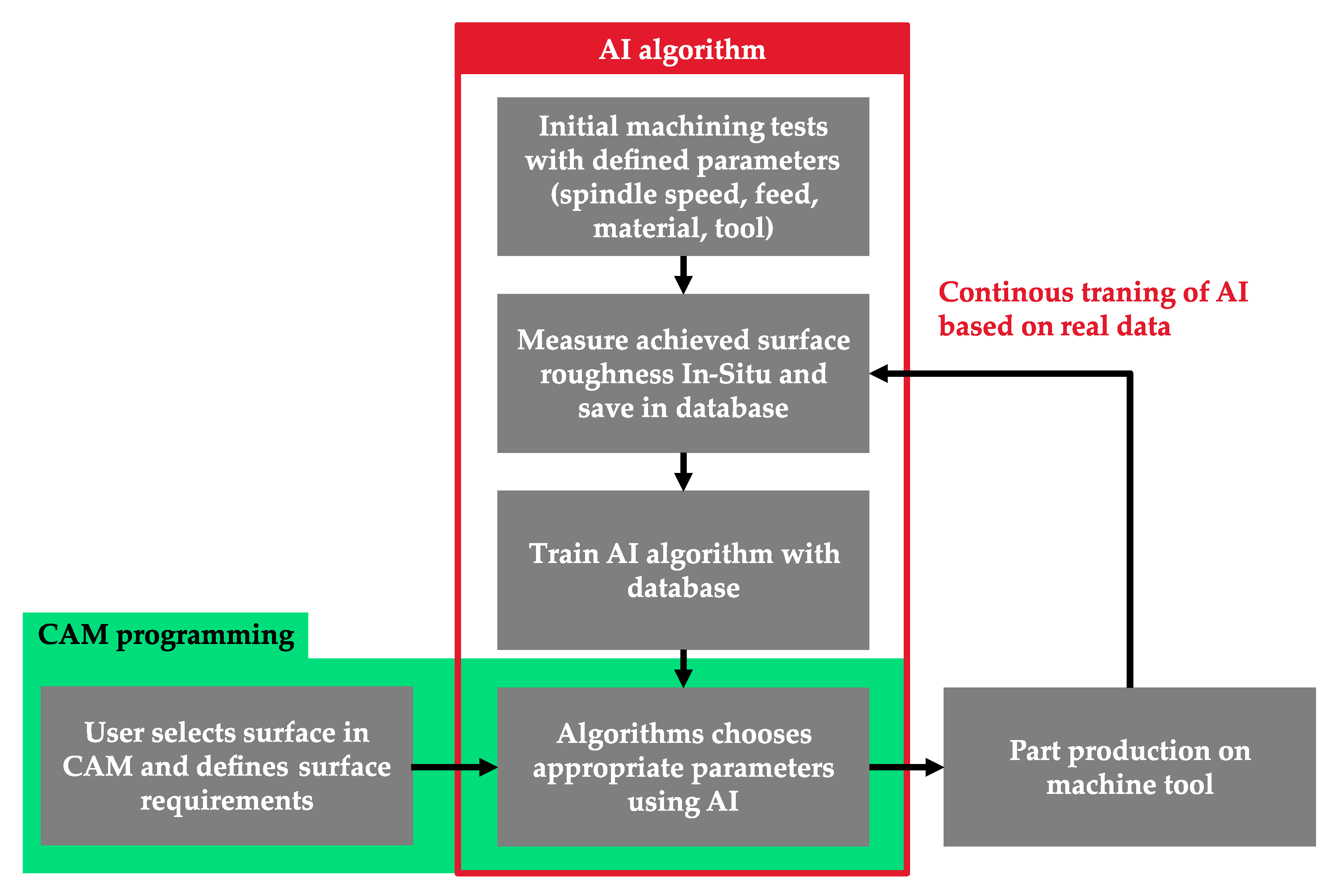
In the future, the integrated roughness measurement system can be used to automatically train an artificial intelligence to select production parameters such as feed rate or speed. For this algorithm, all conceivable combinations of speed, feed, material, and machining tool should be systematically tested on a machine tool in a large-scale test series and the resulting surface quality measured in each case, with the data stored in a database until the test series is complete. In addition, useful metadata such as the duration or the power consumption should be stored. When all the values have been recorded, they can be used to train a neural network. Finally, the algorithm needs to work in the opposite direction. This means that the user specifies the surfaces that should have a certain surface quality after production in the CAM system, then the algorithm provides the best production parameters to achieve the desired machining. With the help of the co-trained metadata, the selection of preferences such as short machining time, wear optimisation, or energy-saving production will be possible [
25]. Until now, machining parameters have always needed to be set manually during CAM programming, often based on tables and operator experience. Unfortunately, this means that there is less reproducibility and that the most optimal parameters are rarely used.
The use of the algorithm described above can increase the speed and comfort of programmers while optimising the overall machining process. It can be continuously optimised and improved by feeding back the actual data used, including the real measurement data, into the algorithm.
Figure 7 shows the algorithm and procedure schematically.
4.5. Cloud-Based Machining Parameters
Outsourcing the parameter selection to a cloud would be an extension of the previously presented algorithm. In this case, the user would only have to specify some primary data, such as material, selected tool, and optional preferences on a website, in an app, or in a CAM plugin. The algorithm described in the previous chapter runs on a central server and calculates the optimal parameters, which are sent back to the user. Outsourcing to the cloud has the great advantage that the entire community using the algorithm can train it further by feeding back real data (if desired and if a measuring device is available). When the algorithm is sufficiently well trained and verified, it is possible to eliminate the need to measure in the machining process and simply trust the algorithm, as the produced surface is highly likely to be of the required surface quality. Finally, the desired roughness can be defined in the CAM system and all manufacturing parameters for an optimised manufacturing process can be automatically calculated.
5. Discussion
The results obtained in this project indicate the potential benefits of integrating roughness measurement into machine tools for industrial applications. The successful development of a prototype for in situ roughness measurement represents a significant step towards achieving automated and standardized surface quality inspection. However, several critical points and areas for further exploration and improvement have been identified during the course of this project.
- 1.
Repeatability and Accuracy: One of the most crucial aspects in the implementation of roughness measurement in machine tools is ensuring the repeatability and accuracy of the measurements. While the prototype has shown promising results, more extensive testing is required under various real-world conditions to assess its performance robustness. Understanding the influence of environmental factors, such as vibrations, temperature variations, and machining parameters, is essential in order to optimize the system’s precision and provide reliable measurement results.
- 2.
Industrial Environment Suitability: Machine tools operate in a challenging industrial environment, with various sources of disturbance and potential interference that may affect measurement accuracy. The prototype’s response to external factors, such as machine tool movements, coolant flow, and nearby machining processes, needs to be carefully examined. Measures to minimize these interferences, such as improved mechanical stability, sensor design, and advanced signal processing algorithms, should be explored to ensure accurate measurements in real-world production settings.
- 3.
User-Friendly Interface: The adoption of any new technology relies heavily on its user-friendliness and seamless integration into existing processes. The development of an intuitive and easy-to-use interface for the roughness measurement system is paramount. Machine operators and production staff should be able to interact with the system effortlessly without requiring specialized training in metrology. The aim should be to create a plug-and-play solution that minimizes downtime and maximizes productivity.
- 4.
Standard Compliance: Ensuring that the roughness measurements conform to established international standards is essential for the widespread acceptance of the system. While the prototype has shown promising comparability in traditional measuring rooms, further verification and certification against recognized standards should be pursued in order to instill confidence in potential customers about the accuracy and reliability of the measurements.
- 5.
Cost-Effectiveness: For successful adoption by industry, the integrated roughness measurement system must demonstrate cost-effectiveness and offer tangible benefits. The initial development costs and potential savings in production time, scrap reduction, and tool life optimization should be thoroughly evaluated in order to present a compelling business case for potential customers.
- 6.
Industry-Specific Applications: Identifying and focusing on industry-specific applications where the integrated roughness measurement system can offer the most significant advantages is essential. Targeting sectors with strict quality requirements, such as the medical technology, aerospace, and automotive sectors, may provide an excellent starting point for market penetration.
- 7.
Future Potential: The potential for artificial intelligence-based optimization of machining parameters is a promising avenue for future development. By training algorithms to select the best production parameters based on real-world data, manufacturing processes can be optimized for efficiency, quality, and resource conservation. There seems to be great potential in the combination of AI and roughness data.
6. Conclusions
In summary, the integration of roughness measurement into machine tools represents a promising advancement in production metrology. However, the path to successful implementation involves addressing various challenges, including repeatability, accuracy, user-friendliness, and compliance with standards. Future research and development efforts should focus on further refining the prototype, conducting extensive testing under real-world conditions, and establishing partnerships with industrial partners to ensure the system’s practicality and viability in the manufacturing industry. Only through continuous improvement and by addressing critical aspects can the integrated roughness measurement system become a valuable and widely adopted tool in industrial applications.
7. Patents
A patent has been filed with the German Patent Office and remains under examination.
Author Contributions
Conceptualization, F.B. and C.S.; hardware, C.S.; software, C.S.; validation, C.S.; investigation, C.S.; resources, C.S.; writing—original draft preparation, C.S.; writing—review and editing, F.B. and C.S.; supervision, F.B.; project administration, C.S. All authors have read and agreed to the published version of the manuscript.
Funding
This research was funded by the German company Mahr GmbH.
Data Availability Statement
No further data are publicly available on this project due to confidentiality agreements and ongoing patent applications.
Conflicts of Interest
The authors declare no conflict of interest.
Abbreviations
The following abbreviations are used in this manuscript:
| CAD | Computer-Aided Design |
| CAM | Computer-Aided Manufacturing |
| CNC | Computerized Numerical Control |
References
- Sauer, O.; Haller, M.L.; Wagner-Sardesai, S.; Henke, J.; Schmelting, J.; Meyer, T.; Kujath, M.; Seidel, H.; Kuhn, T.; Schnicke, F.; et al. Manufacturing-X: Die Branche der Fabrikausrüster. Fraunhofer-Gesellschaft 2023. [Google Scholar] [CrossRef]
- Quality Engineering. Messtechnik Wird in der Digitalen Fabrik Zunehmend Intelligent. 2023. Available online: https://quality-engineering.industrie.de/top-news/messtechnik-wird-in-der-digitalen-fabrik-zunehmend-intelligent/ (accessed on 28 January 2023).
- Pan, Y.; Zhou, P.; Yan, Y.; Agrawal, A.; Wang, Y.; Guo, D.; Goel, S. New insights into the methods for predicting ground surface roughness in the age of digitalisation. Precis. Eng. 2021, 67, 393–418. [Google Scholar] [CrossRef]
- Li, B.; Tian, X.; Zhang, M. Modeling and Multi-objective Optimization Method of Machine Tool Energy Consumption Considering Tool Wear. Int. J. Precis. Eng. Manuf.-Green Technol. 2022, 9, 127–141. [Google Scholar] [CrossRef]
- OTEC Präzisionsfinish GmbH. Makellose Oberflächen für die Luftfahrt. JOT J. Oberflächentechnik 2021, 61, 86–89. [Google Scholar] [CrossRef]
- Marxer, M.; Bach, C.; Keferstein, C.P. Fertigungsmesstechnik: Alles zu Messunsicherheit, Konventioneller Messtechnik und Multisensorik, 10th ed.; vollständig überarbeitete und erweiterte Auflage; Springer eBook Collection, Springer Vieweg: Wiesbaden, Germany, 2021. [Google Scholar] [CrossRef]
- Pawlus, P.; Reizer, R.; Wieczorowski, M.; Krolczyk, G.M. Study of surface texture measurement errors. Measurement 2023, 210, 112568. [Google Scholar] [CrossRef]
- Seyler, T. Digitale Holographie in der Werkzeugmaschine; Books on Demand: Norderstedt, Germany, 2020. [Google Scholar]
- DIN EN ISO 3274:1998-04; Geometrical Product Specifications (GPS)—Surface Texture: Profile Method—Nominal Characteristics of Contact (Stylus) Instruments (ISO 3274:1996). German Version EN ISO 3274:1997; ISO: Geneva, Switzerland, 1998.
- DIN EN ISO 21920-1:2022-12; Geometrical Product Specifications (GPS)—Surface Texture: Profile—Part 1: Indication of Surface Texture (ISO 21920-1:2021). German Version EN ISO 21920-1:2022; ISO: Geneva, Switzerland, 2022.
- Gao, W.; Haitjema, H.; Fang, F.Z.; Leach, R.K.; Cheung, C.F.; Savio, E.; Linares, J.M. On-machine and in-process surface metrology for precision manufacturing. CIRP Ann. 2019, 68, 843–866. [Google Scholar] [CrossRef] [Green Version]
- Renishaw. SFP2 Rauheitsmesstaster für das REVO® Messsystem. Available online: https://www.renishaw.de/de/sfp2-rauheitsmesstaster-fuer-das-revo-messsystem–10823 (accessed on 2 June 2023).
- Zeiss. Zeiss Rotos - Die neue Dimension der Rauheitsmessung. Available online: http://pages.zeiss.com/rs/896-XMS-794/images/DE_ZEISS_ROTOS_digital.pdf (accessed on 2 June 2023).
- Blum Novotest. Rauheitsmessgeräte. Available online: https://www.blum-novotest.com/produkte/blum-messkomponenten/rauheitsmessgeraete/ (accessed on 27 June 2023).
- Volk, R. Rauheitsmessung—Buch mit E-Book: Theorie und Praxis, 3rd ed.; überarbeitete ausgabe; Beuth Praxis, Beuth: Berlin, Germany, 2018. [Google Scholar]
- Podulka, P. Suppression of the High-Frequency Errors in Surface Topography Measurements Based on Comparison of Various Spline Filtering Methods. Materials 2021, 14, 5096. [Google Scholar] [CrossRef] [PubMed]
- Tian, Y.; Liu, X.; Chetwynd, D.G.; Shirinzadeh, B.; Zhang, D. Vibration analysis of stylus instrument for random surface measurement. Precis. Eng. 2010, 34, 586–591. [Google Scholar] [CrossRef] [Green Version]
- Mahr GmbH. MarSurf XR 1. Available online: https://metrology.mahr.com/fileadmin/assets/files/MarSurf--XR%201--3764783--FL--DE--2020-04-15.pdf (accessed on 2 June 2023).
- Breitmeier Messtechnik. Tactile Probes. Available online: https://breitmeier.de/tactile-probes/ (accessed on 30 June 2023).
- DIN EN ISO 5436-1:2000-11; Geometrical Product Specifications (GPS)—Surface Texture: Profile Method; Measurement Standards—Part 1: Material Measures (ISO 5436-1:2000). German version EN ISO 5436-1:2000; ISO: Geneva, Switzerland, 2000.
- Haitjema, H. Uncertainty in measurement of surface topography. Surf. Topogr. Metrol. Prop. 2015, 3, 035004. [Google Scholar] [CrossRef]
- Leach, R.; Haitjema, H. Bandwidth characteristics and comparisons of surface texture measuring instruments. Meas. Sci. Technol. 2010, 21, 9. [Google Scholar] [CrossRef]
- BIPM; IEC; IFCC; ILAC; ISO; IUPAC; IUPAP; OIML. Evaluation of Measurement Data—Supplement 1 to the “Guide to the Expression of Uncertainty in Measurement”—Propagation of Distributions Using a Monte Carlo Method. Joint Committee for Guides in Metrology, JCGM 101:2008. Available online: https://www.bipm.org/documents/20126/2071204/JCGM_101_2008_E.pdf/325dcaad-c15a-407c-1105-8b7f322d651c (accessed on 2 June 2023).
- Liu, L.; Zhang, X.; Wan, X.; Zhou, S.; Gao, Z. Digital twin-driven surface roughness prediction and process parameter adaptive optimization. Adv. Eng. Inform. 2022, 51, 101470. [Google Scholar] [CrossRef]
- Feng, C.; Guo, H.; Zhang, J.; Huang, Y.; Huang, S. A systematic method of optimization of machining parameters considering energy consumption, machining time, and surface roughness with experimental analysis. Int. J. Adv. Manuf. Technol. 2022, 119, 7383–7401. [Google Scholar] [CrossRef]
| Disclaimer/Publisher’s Note: The statements, opinions and data contained in all publications are solely those of the individual author(s) and contributor(s) and not of MDPI and/or the editor(s). MDPI and/or the editor(s) disclaim responsibility for any injury to people or property resulting from any ideas, methods, instructions or products referred to in the content. |
© 2023 by the authors. Licensee MDPI, Basel, Switzerland. This article is an open access article distributed under the terms and conditions of the Creative Commons Attribution (CC BY) license (https://creativecommons.org/licenses/by/4.0/).


