Article

A Novel Approach for Maintenance and Repair of Reinforced Concrete Using Building Information Modeling with Integrated Machine-Readable Diagnosis Data

by
Hendrik Morgenstern
* and
Michael Raupach
Institute for Building Materials Research(ibac), RWTH Aachen University, 52062 Aachen, Germany
*
Author to whom correspondence should be addressed.
Constr. Mater. 2022, 2(4), 314-327; https://doi.org/10.3390/constrmater2040020
Submission received: 27 October 2022 / Revised: 9 December 2022 / Accepted: 13 December 2022 / Published: 16 December 2022
(This article belongs to the Special Issue Advances in Concrete Binders and Reinforced Concrete)

Abstract

:
Building Information Modeling (BIM) is increasingly establishing a model-based work process in the construction industry. Though it can be considered the standard for the planning of new buildings, the use cases for existing buildings are still limited. Nonetheless, BIM models provide promising possibilities which are increasingly being researched in different fields of application. At the Institute for Building Materials Research (ibac) at RWTH Aachen University, a novel approach for maintenance and repair of reinforced concrete is being developed, using BIM models enriched with machine-readable diagnosis data. This paper proposes a digital workflow and highlights the added value for planning repair measures. Using BIM in maintenance and repair can accelerate the planning process and decrease the required material consumption for the execution.

1. Introduction

BIM has been gaining interest for several years now and has even become mandatory in countries such as the United Kingdom, Singapore, and Germany [1]. Nowadays, BIM can be considered state of the art or even the standard for the planning process of new construction projects. For maintenance and repair projects, BIM has yet to reach that level of implementation in the industry. Probably the most obvious hurdle when using BIM for existing structures in need of repair is the need for a BIM model, which is almost certainly non-existent. This need for a model might be inevitable, but the required resources to generate such a model are steadily decreasing as there are great efforts regarding the automatization of this process [2,3,4,5].
An extensive review of BIM applications in maintenance identified major gaps in the enrichment of IFC files, the consideration of environmental effects as well as the optimization and management of data [6]. There are several approaches to close these gaps, for example by combining BIM with IoT-Technologies (Internet of Things) and monitoring indoor conditions such as temperature and carbon dioxide content [7] or power consumption and luminance [8]. Many of these approaches originate from the facility management of smart buildings, where BIM is already in use. However, there are also efforts to digitalize existing and even historic structures. One example of the so-called heritage BIM (HBIM) can be found in [9].
If the goal is to utilize BIM for structural maintenance, BIM can be combined with bridge monitoring systems (BMS) [10] or structural health monitoring (SHM) to achieve structural health BIM (shBIM) [11]. These applications hold great potential to increase the efficiency and effectiveness of planning and execution processes. However, the digital workflows are often not seamless and rely on further software and platforms as BIM lacks semantic completeness, diminishing the interoperability. An example of the extension of interoperability is given in [12], where BIM is used to monitor the maturity of concrete in sensor-equipped formwork.
When BIM is enriched with further information content and functionality, it transitions towards the digital twin (DT). For a more precise definition of (construction) digital twins and its distinction to BIM, refer to [13]. The vision of digital twin construction (DTC) proclaims a data-centric mode of operation that combines monitoring systems, as-built-models, and artificial intelligence to achieve condition assessments in real-time as well as predictions for the future.
DTC could also include aspects of Lean Management and other optimization processes, as stated in [14]. The application of BIM and its derivatives is not limited to the stationary computer and planning processes, as it gets transferred to the construction site while using mixed reality to visualize defects and analyze them on site [15]. More research on the combination of augmented reality (AR) and virtual reality (VR) with BIM and DTs is reviewed in [16].
Several of the sources mentioned above conclude significant importance in ensuring interoperability and extending the functionality of BIM. The applications in maintenance and repair are existent but very limited. Additionally, despite all of the technological possibilities and high-tech solutions, the economic benefits resume being unclear [17]. The research presented in this paper attempts to tackle these crucial points and enable the cost-effective usage of BIM for the maintenance of existing structures. On a practical example, the enrichment of BIM with data from building diagnoses or monitoring systems is demonstrated while maintaining interoperability by using only BIM software and the IFC format. Furthermore, the functionality of BIM regarding repair and maintenance is expanded by implementing algorithms for structural assessments. Through applying the results on-site via AR, the concept of DTC is presented vividly. Parts of this research were recently presented at the International Symposium on Nondestructive Testing in Civil Engineering (NDT-CE) in Zurich [18] and at the International Conference on Concrete Repair, Rehabilitation and Retrofitting (ICCRRR) in Cape Town [19].

2. Materials and Methods

To enable BIM-based planning of maintenance and repair measures, the BIM model has to be enriched with information and functionality. In the following examples, an underground car park in need of repair was used as an on-site laboratory. At first, a point cloud of the site was created using a laser scanner (RTC360 by Leica Geosystems). Afterward, a BIM model was manually derived from this point cloud. Diagnosis data from a previously conducted building diagnosis as well as algorithms for decision support were implemented into this model. The functionality and compatibility with the open data format of the industry foundation classes (IFC) were ensured at all stages. Hence, all processes could be carried out in the BIM software to functionalize the BIM model as a Single Source of Truth (SSoT).

2.1. Implementation of Diagnosis Data

2.1.1. Requirements

There is a variety of BIM software available, some of them are specialized in certain tasks, and others are optimized for collaborative work processes. For the conducted research, the most important aspect of the software was to provide an application programming interface (API) to enable the programming of specific features, which are not provided in commercial software yet. As Revit (Autodesk) provides the plugin Dynamo (Autodesk) for visual programming, which can be considered relatively intuitive and is also compatible with conventional programming using Python, this software was chosen. For more information on Dynamo and visual programming, refer to [20]. That said, almost no original function of Revit was used for the following tasks. Instead, Dynamo and Python were used to create and implement the required functionality. One advantage of Dynamo, besides opening the BIM model for individual algorithms, is that it provides a graphical user interface (GUI) for the sub-programs/scripts, which increases user-friendliness and facilitates the usage of the individual sub-programs.
All data which had to be implemented into the BIM model was provided in CSV files, as most measuring device software support this file format when exporting the datasets. For each type of data, a Revit family was created and customized to carry geometric and semantic information (properties) according to the individual requirements. After enriching the model in Revit using Dynamo and Python, the model was exported as an IFC file and viewed in the BIM viewer BIMvision (Datacomp) to validate the IFC conformity. In several examples, the implemented data were color-coded to maximize visual clarity. This was either achieved by assigning material colors to the pertaining elements or by coloring the elements based on selected properties using the BIMvision-plugin Advanced Reports.
Python constitutes the part of the workflow, where the most complex processes were carried out. Many software developers provide wrappers to use their software via Python, which vastly increases the range of functions. In this research, CloudComPy, the wrapper for the open source point cloud software CloudCompare, and PySMILE, the wrapper for the Bayesian statistics engine SMILE (BayesFusion), were implemented. In doing so, the enrichment of BIM with the functionality of other software was achieved. The used version of Python needs to be compatible with the installed version of Revit to be accessible via Dynamo. All software and their according versions are given in Table 1.
The way of implementing data in the BIM model varies significantly from the structure of the dataset to how it was measured and located. In the following sections, the implementation is divided into one-, two- and three-dimensional data.

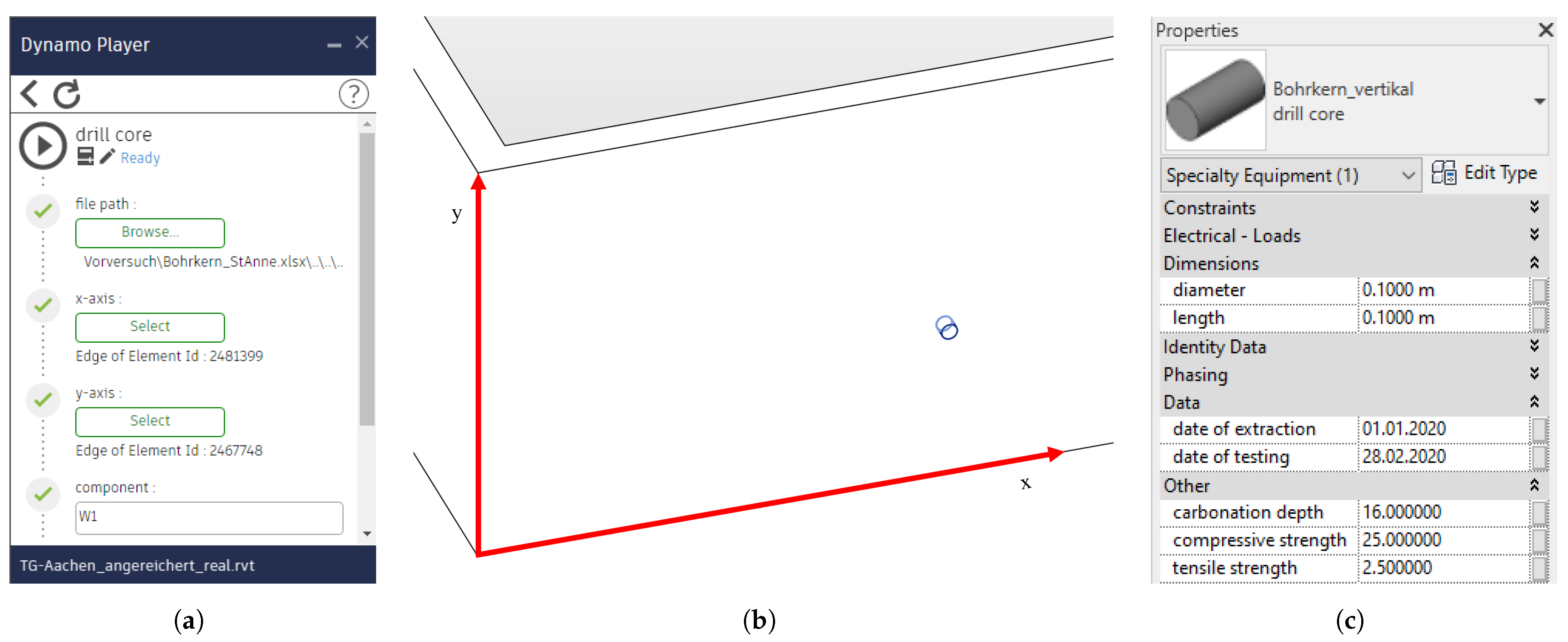
2.1.2. One-Dimensional Data

Examples of one-dimensional data may be drill cores containing information about compressive strength and carbonation depth or drill dust extraction probes containing information about the depth-graded chloride content. Such samples are often located in a local coordinate system relative to the component on which the tests were carried out. Assuming that the data are gathered in a CSV file containing information about the local coordinates, geometric features (e.g., depth and diameter of the drill core), and of course the results of the analysis (compressive strength, etc.), the file can be imported using the GUI of the Dynamo Player (Figure 1a). After selecting the x- and y-axis and implementation (Figure 1b), the element contains all given data (Figure 1c).
This procedure works the same way for multiple samples. In this case, the component can be defined (for example “Wall 1”) and all pertaining elements given in the input file get implemented at once. The script is robust regarding orientation and works for walls, columns, floors, ceilings, or any flat element. The implemented elements are rotated automatically according to the local coordinate system and the orientation of the selected component.

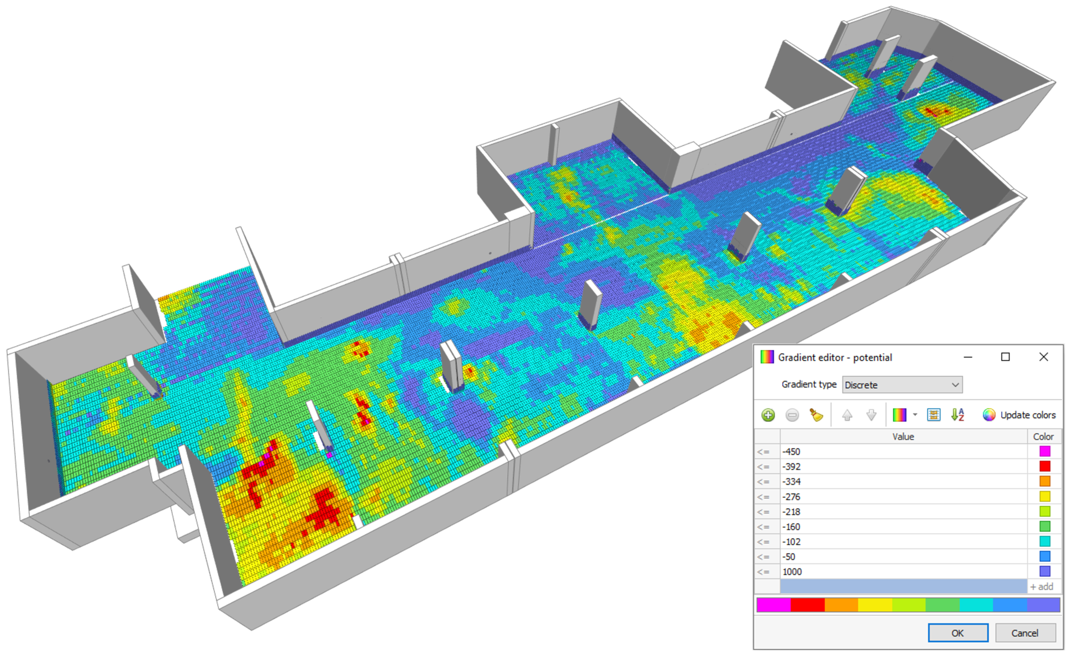
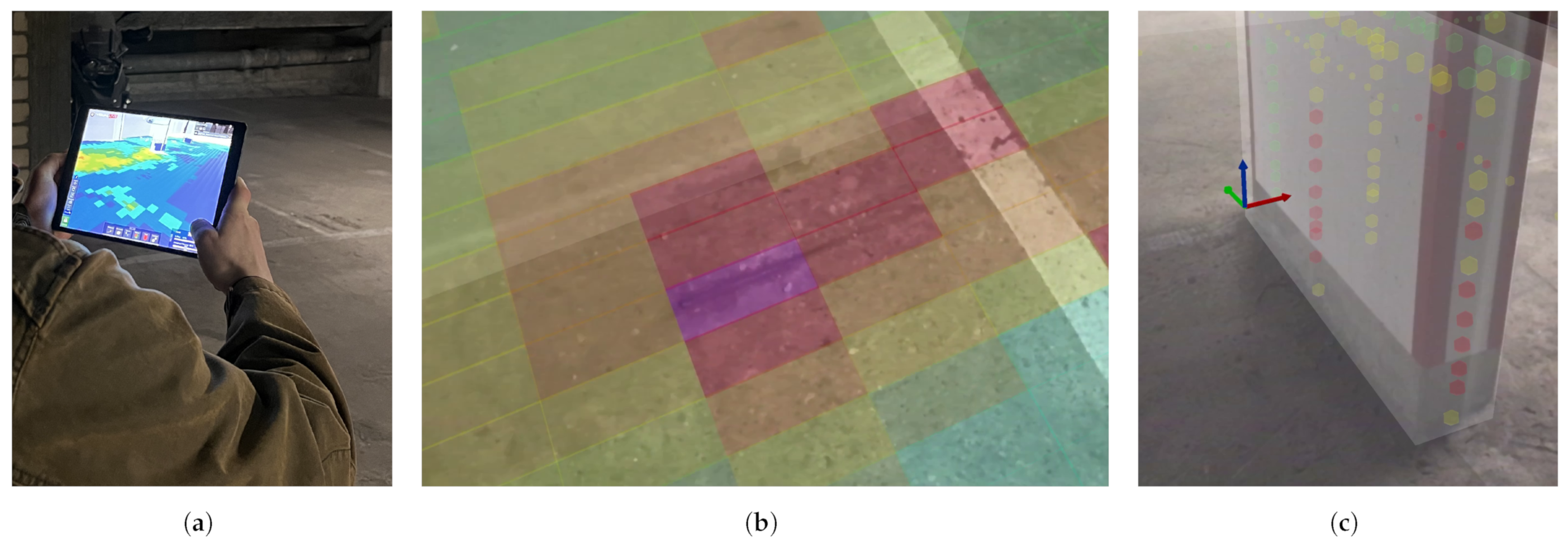
2.1.3. Two-Dimensional Data

To assess the corrosion probability of the steel reinforcement, a half-cell potential measurement can be carried out. The obtained datasets can be implemented similarly as shown in Figure 1. As the half-cell potential mapping is an areal diagnosis, the input file contains a grid of measurements in a local coordinate system. For each line in the CSV file, a tile is placed in the model carrying the measured potential in mV. These tiles can be exported to IFC and viewed color-coded using BIMvision as seen in Figure 2.
A more complex example is the measurement of concrete cover over the rebars in a column. For one column, five data sets were obtained using a reinforcement detection device–one vertical scan at each side and one horizontal scan around all four sides at once. The implementation of the vertical scans works similarly to the examples above. For the implementation of the horizontal scan, a special case occurs as the measured dataset reaches over four local coordinate systems. In this case, four x-axes can be selected instead of one, and the algorithm shifts and rotates the local coordinate system each time the measuring section exceeds the length of the respective side of the column. GUI and results of the implementation of concrete covers are given in Figure 3. The shown elements were implemented with their true size (or rather rebar diameters).
This way of implementation could be transferred to datasets obtained through other methods as well. For example, thermography can be used to detect damages in concrete components [21], cracks can be detected using image processing as reviewed in [22], and further information about rebars can be gathered using ground penetrating radar [23]. All these methods could be use cases for the machine-readable implementation of two-dimensional datasets in BIM.

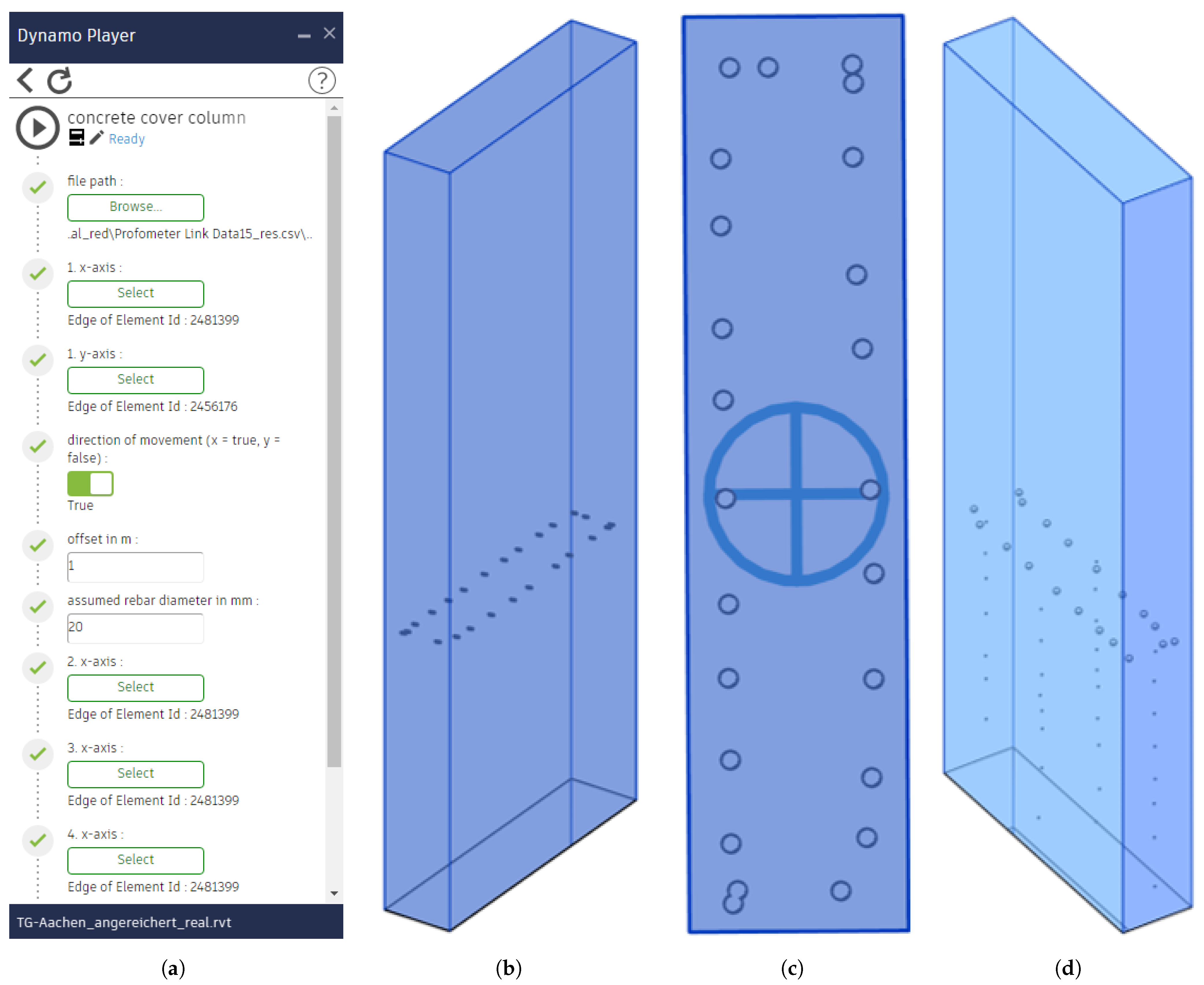
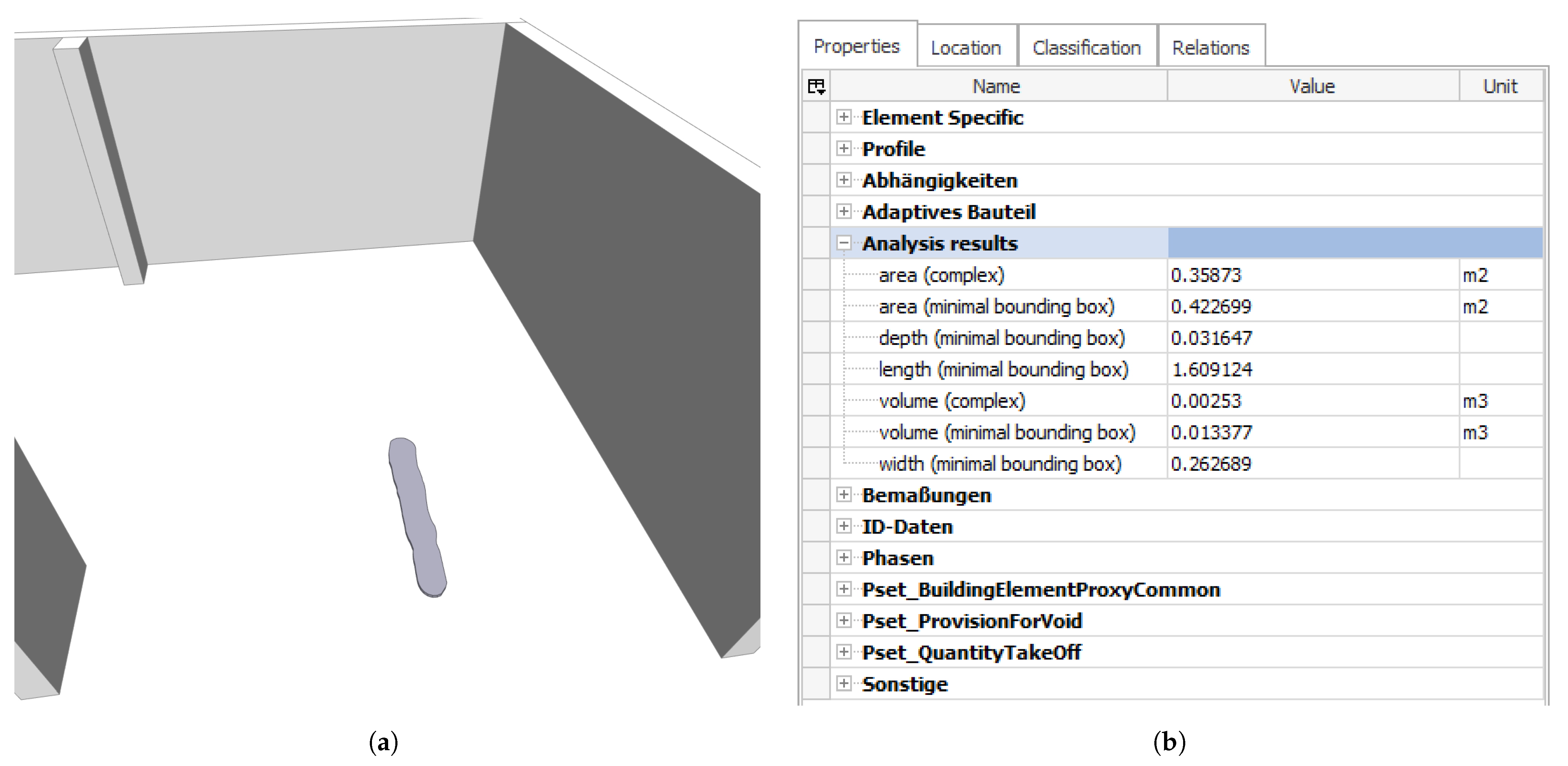
2.1.4. Three-Dimensional Data

The structure was laser-scanned to obtain the required point cloud for BIM modeling. This point cloud contains spatial information about the geometric features of the components which can be utilized to characterize the components or even detect damages. There are several applications of laser scanners for change detection, for example, the displacement of retention structures [24] or the comparison of complex topography [25]. This procedure can be transferred to the context of concrete spalling or ultimately any change in geometry. If multiple point clouds are available, prior to and posterior to the formation of a damage, the change detection can be achieved quite easily using software such as CloudCompare. Realistically, for existing structures in need of repair, it is unlikely that a prior-point-cloud is available. In this case, the posterior-point-cloud can be analyzed using contour detection. For further information regarding contour detection in point clouds, refer to [26,27]. In the following example, a case of concrete spalling was analyzed using CloudComPy to calculate the surface variation of the point cloud.
Figure 4a shows the concrete spalling which was about 1.6 m long as a point cloud. In Figure 4b, the same section is given, but the point cloud was colored according to the surface variation. Simplified, it can be said that areas with high deviations from planarity are red and even areas are blue. The red border in Figure 4b was detected by the algorithm and drawn automatically. This border marks the boundaries of the spalling damage and can be calculated given any tolerance limit. In the next stage of the algorithm, the damage is cropped, and the original surface gets approximated by fitting a plane through the red border line. Figure 4c shows the orthogonal distance between the as-is-surface of the damage and the fitted plane as a color gradient.
Furthermore, the smallest width, greatest length, and deepest depth are calculated for the cropped damage and for the minimal bounding box (smallest enclosing cuboid). Additionally, area and volume are calculated for the real geometry and minimal bounding box. Finally, the damage can be implemented as a geometric element in BIM (Figure 5a), carrying all information of the geometric analysis (Figure 5b). Opposing to the implementation of one- or two-dimensional data, in this case, the data are given in a global coordinate system. If the damage analysis derived from the same point cloud as the BIM model itself, the coordinate systems may converge, causing no further need for transformation. An algorithm was developed to transform the coordinate systems in case the damage analysis originates from another point cloud. To do so, three adjoining surfaces need to be selected in CloudCompare and have their normal vectors exported as a CSV file. Afterward, a Dynamo script imports this file and allows the selection of the same three surfaces, resulting in a coordinate transformation matrix and allowing the correct placement of input data from the external coordinate system. The BIM implementation of damages can be used to calculate areas and volumes in need of repair. Furthermore, as some materials or methods are only applicable for damages of certain sizes, the geometrical analysis can support the automated assessment as shown in the following.

2.2. Automation of Analysis

2.2.1. Data Preparation

Several datasets obtained from the building diagnosis have now been implemented in the BIM model in a machine-readable manner. Machine readability is of great significance for the following steps as it allows efficient data handling. For example, the BIM model contains the concrete cover as elements in several components. However, the model does not “know” which concrete-cover-element relates to which side of the component by default. To achieve an automated analysis, the data need to be processed automatically as well. Thus, algorithms were developed to prepare the data as required for further calculations.
To remain at the example of the concrete cover, there is not only the need for a relation between elements and component sides but also for a relation between the different concrete cover elements as the rebars are installed in different layers. Conveniently, while the concrete cover varies, the elements of the vertical or horizontal scans are ordered in a straight line when projected to the surface of the respective surface.
Thus, in the first step, the algorithm shifts each concrete cover element in the direction in which the distance to the next component surface equals the concrete cover. Secondly, the algorithm groups the different elements in straight lines for each component side. Thirdly, the mean concrete cover is calculated for each line, enabling a statement about which line belongs to the front or rear layer of rebars. Afterward, the concrete covers are grouped usefully to be further processed. One example of such a post-process is shown in Figure 6, where the 5% quantile of the concrete cover from the front reinforcement layer is color coded for walls and columns.

2.2.2. Decision Trees for Maintenance Methods

Now that the diagnosis data are implemented and prepared, it can be used to assess the condition of the structure and support the decision-making regarding the choice of repair measures. Principles and methods for repair and prevention of reinforced concrete structures in need of repair are given internationally in the ISO 16311-3 [28], for Europe in the EN 1504-9 [29] and for Germany in the technical standard “Maintenance of Concrete Structures” (TR IH) [30]. The latter one is best suited for the use case to be demonstrated, as it provides specific boundary conditions and limits for the applicability of methods for rebar corrosion. This is of relevance as, for the automated assessment of methods, appropriate decision trees need to be implemented via Python/Dynamo.
In the next example, the workflow for method 7.2 “Replacing contaminated or carbonated concrete” is demonstrated. For this method, the TR IH provides the following criteria:
A
Reinforcement locally or fully depassivated by carbonation;
B
Critical, corrosion-inducing chloride content locally or fully exceeded;
C
In case of carbonation depth exceeding the depth of the reinforcement layers, concrete removal up to 10 or 15 mm behind the reinforcement, for steel bar diameters < or ≥16 mm;
D
In case of large chloride penetration depths, remove concrete up to at least 30 mm behind the reinforcement in such a way that the chloride content does not exceed 1.5 wt% relative to the cement content
According to TR IH, method 7.2 is applicable, if A and/or B are fulfilled. In this case, the required depth of concrete removal d c r is calculated according to Equation (1).
d c r { d c if not C d c l , c r i t if not D c + d r + 10 if C c + d r + 30 if D d c l = 1 . 5 if D
d c r : depth of concrete removal in mm
d c : depth of carbonation in mm
d c l , c r i t : depth of critical chloride content in mm
c : concrete cover in mm
d r : rebar diameter in mm
d c l = 1.5 : depth of 1.5 wt% chloride content in mm
As the BIM model has access to all required information to calculate Equation (1), the assessment of method 7.2 can be achieved automatically. This procedure is viable for virtually any method, as long as an appropriate decision tree can be defined. The results of these assessments are stored in an additional layer-element, attached to the respective surface of the components, and exported as CSV files as well. The CSV-exports of the analyses allow further processing, if needed, such as plotting the results or generating a report. If this is achieved using Python, it can also be included in the Dynamo script. In any case, the CSV files ensure transparent storage of the analyses and calculations and enable further interoperability.

3. Results

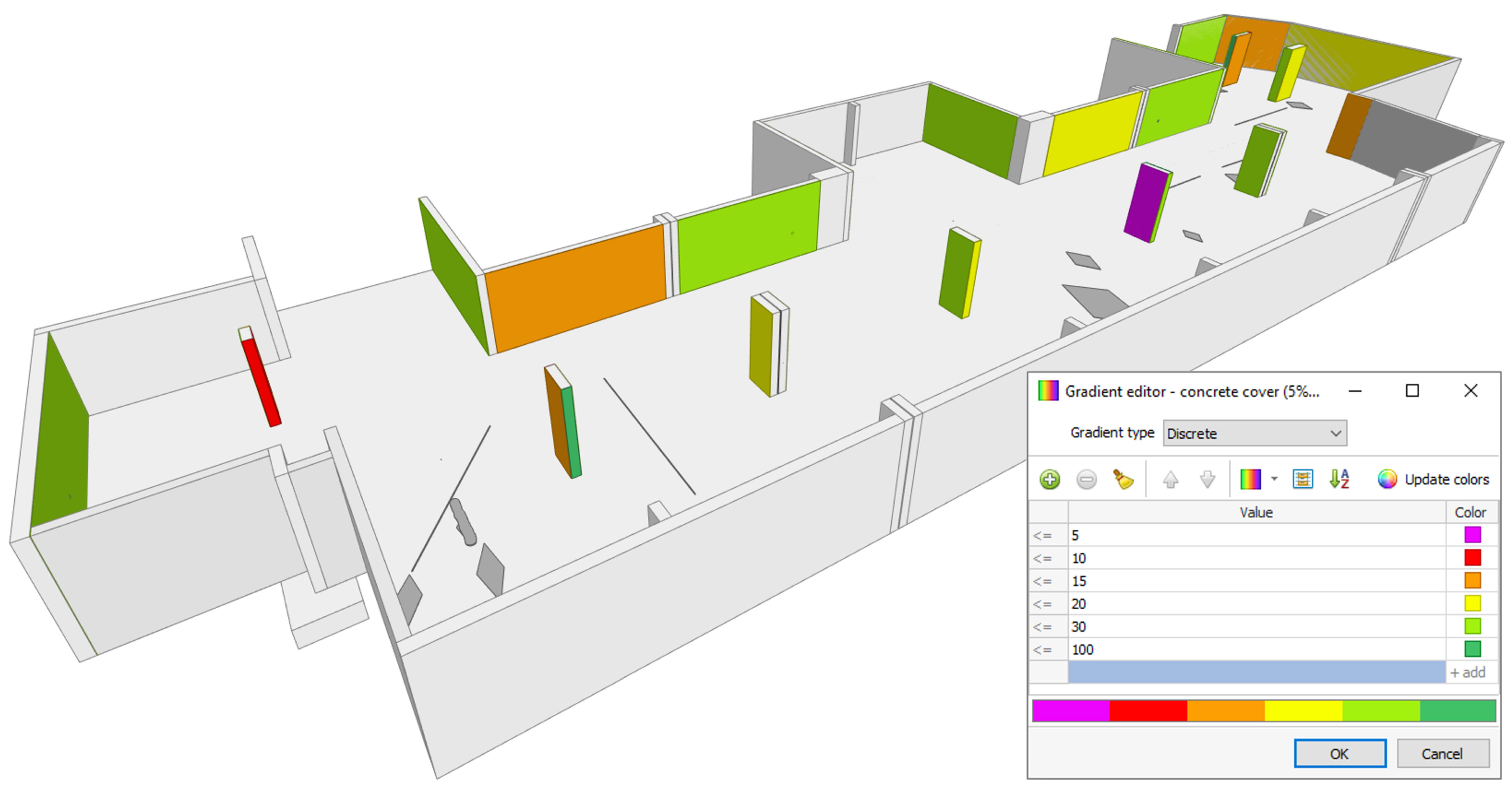
3.1. Multi-Layered Visualization of the As-Is-State

BIM models that have been enriched as demonstrated above allow the visual evaluation of the as-is-state by showing and/or hiding any implemented diagnosis data and the calculations carried out. The elements of different layers can be color-coded or scaled at will. This allows the graphical comparison of different datasets and measuring methods as well as a quick understanding of the building condition. As mentioned in the introduction, AR-technologies are increasingly finding application on construction sites and interoperability is significant when establishing new BIM procedures. To demonstrate an example of the visualization of different layers on site, the IFC files were imported into the VR software MobiLive (VisualLife). The results are shown in Figure 7.

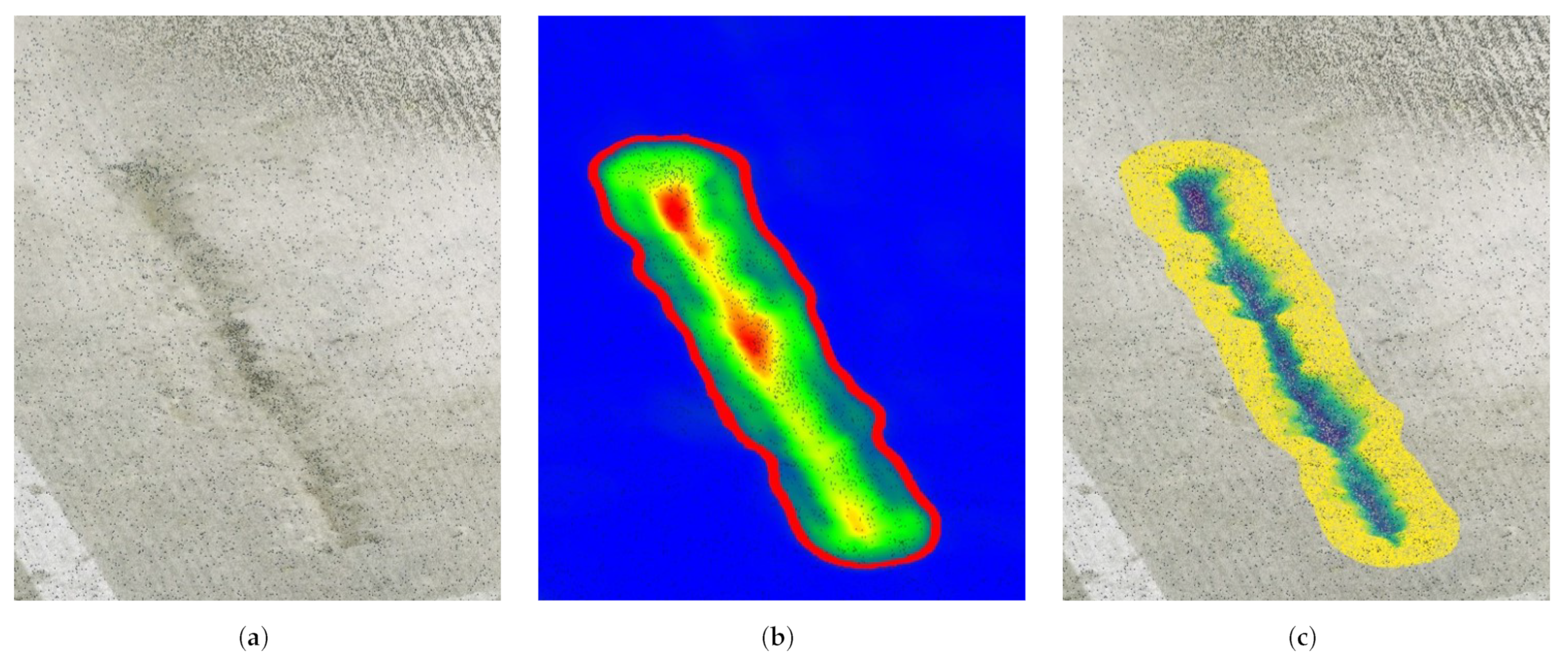
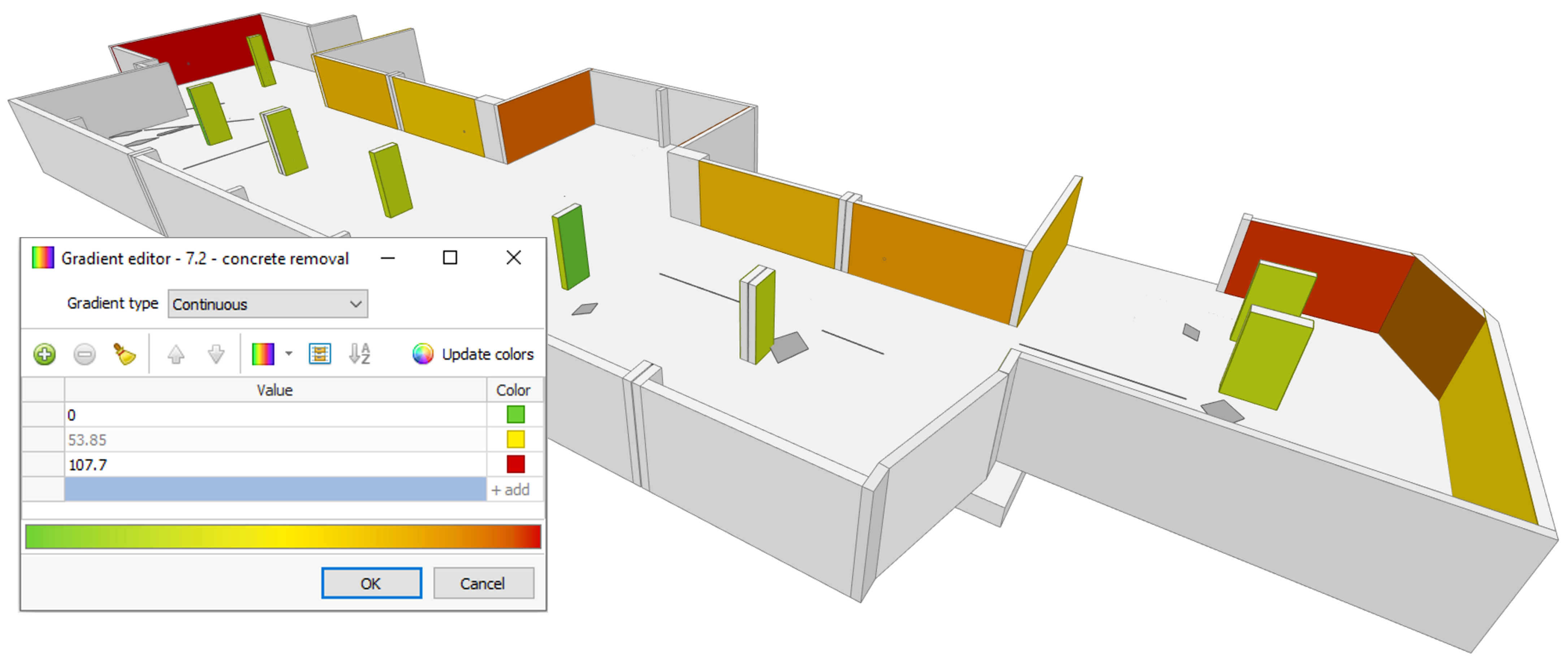
3.2. Spatially Resolved Condition Assessment

The implementation of machine-readable data allows the enhancement of BIM using Python algorithms, increasing its functionality significantly. Users of the enriched BIM model can select any components of interest and execute a program for the condition assessment and decision support. The algorithm then gathers all available information about depth-graded chloride contents, carbonation depths, etc., and compares them with the relevant properties of the concrete cover. Based on several decision trees for the different methods, the algorithms create new elements carrying the results of the analyses. Figure 8 shows the required concrete removal in mm for method 7.2 color-coded for walls and columns. To improve the functionality further, if a method needs the consideration of time or predictions of the condition at the end of the life-cycle, this can also be incorporated into the BIM environment. The algorithms developed in this research use PySMILE to generate and update Bayesian networks based on the available diagnosis data to calibrate corrosion models, allowing relatively precise predictions. This way, the condition assessment is not bound to the present but can also be forecasted for the future.

4. Discussion

BIM models that are enriched as stated above allow clear and understandable assessments and support in identifying critical areas or recognizing spatial correlations, for example eccentricity or inclination of rebar cages. If one side of a column has a particularly high concrete cover and the opposing side a significantly lower, the rebar cage might not have been placed centrically, or if the concrete cover increases on one side and decreases on the opposing side along the height of a column, the rebar cage might be tilted. Such coherences are apparent within minutes of (semi-)automated assessment.
By using decision trees as well as spatial and semantic contexts of the implemented diagnosis data, repair measures can be evaluated automatically. This applies whether one single component is looked at or a group of components is selected. In any way, the respective datasets are taken into account. For example, if five columns are selected, one execution of the script conducts 26 plannings at once–one for the whole group of components, five for the singular columns, and twenty for each side of the columns. These plannings may contain several methods, depending on the available decision trees. Currently, the algorithms developed at ibac consider five methods for rebar corrosion. To emphasize the benefit of this approach, Figure 9 shows the statistics of concrete cover (rear reinforcement layer) and required concrete removal for method 7.2 separately for twelve walls with a cumulative surface of 213.2 m 2 . This overview helps with identifying components with irregularities. For example, the concrete cover in Wall 1 varies heavily, which results in a high 95% quantile. As large chloride depths are the case (criterion D) for this element, a concrete removal of 71.7 + 6 + 30 = 107.7 mm (see Equation (1)) is calculated. For other walls with smaller penetration depths, only the concrete with chloride contents above the critical value needs to be removed (62.8 mm).
The visualization of required concrete removal might be more overseeable if delivered via BIM, as seen in Figure 8. However, Figure 9 allows the reflection of the influence of incremental plannings, for example, twelve individual plannings vs. one planning for twelve walls. The cumulative concrete removal for the incremental approach amounts to 16.0 m 3 , whereas the concrete removal is 19.4 m 3 if only one calculation is carried out for all walls together. In addition, 3.4 m 3 or 17.5 % of concrete removal can be saved by distinguishing between the different walls. Of course, this is just an arbitrary example and the results differ from site to site and according to regulations, limit values, and settings. That being said, it can be expected that the saving potential increases with increasing deviations between the different components. Considering a column with an eccentric rebar cage, the concrete removal could simultaneously be too high and too low, if all sides of the column were included in one sample. Thus, the demonstrated approach can help saving material, time, and ultimately money, contributing to the profitability of BIM-based workflows for maintenance and repair. Certainly, these are not the only resources that can be considered. Additionally to economical benefits, the workflow can easily be expended with aspects of Life Cycle Assessment (LCA) as discussed in [31] or coupled to databases containing LCA datasets as proposed in [32] to regard the economical impact as well when deciding on a repair measure or maintenance strategy. While reducing the amount of required resources, reliability increases as the plannings are specifically adjusted for each component.
The extent of the gain in efficiency and functionality can be increased even more by supporting or automatizing the calculation of costs as the BIM model can access the way and extent of required repair measures. It is even thinkable that timetables or work plans could be extracted by combining the spatially resolved repair demands with BIM-based pathfinding as discussed in [33,34]. Even route planning for autonomous robots as proposed in [35] is possible. The possibilities are mostly restricted by availability of data and decision trees. As a result, BIM can be considered fundamental for the digitalization and automatization of future construction workflows, even for the maintenance and repair of existing structures.

5. Conclusions and Outlook

In this paper, a novel approach for the maintenance and repair of existing structures was demonstrated for an underground car park and components of reinforced concrete. The proposed workflow uses BIM, enriched with machine-readable diagnosis data and decision trees, to automatically assess the as-is-state of components individually or grouped, depending on the selection. Through the use of Bayesian networks, the condition can be assessed in the present as well as in the future. The following conclusions can be drawn from the presented research:
  • BIM can be used effectively for maintenance and repair and is suited to increase the efficiency of both planning and execution;
  • Datasets gained through building diagnoses can be analyzed clearly and quickly by implementing them machine-readably in BIM;
  • The functionality of BIM can be extended significantly by combining BIM with Python and according wrappers using an API;
  • Interoperability of enriched BIM models is vital and can be achieved using transparent file formats such as IFC and CSV;
  • Properly combined, available technologies can be used to establish BIM for maintenance and repair as a profitable and resource-efficient way of working.
In the future, ibac will develop further algorithms and decision trees to provide decision support tools for ideally every method given in ISO 16311-3. It is even thinkable to collaborate with entities providing regulations to achieve smart standards, probably by delivering Dynamo- or Python-scripts for the automated assessment according to the underlying standards. Furthermore, the proposed workflow should be transitioned to open source software such as BlenderBIM using IfcOpenShell. The first attempts to do so proved to be ambitious, but the outcome is considered of great value, especially as it would open the BIM-based approach for maintenance and repair to small and medium enterprises (SME) that cannot afford costly licenses. Providing the whole workflow as an open source package could also accelerate its development and distribution significantly. Ultimately, the workflow should be combined and put to test with monitoring systems, to go one step further toward digital twin construction.

Author Contributions

Conceptualization, H.M. and M.R.; Methodology, H.M. and M.R.; Software, H.M.; Validation, M.R.; Formal analysis, H.M.; Investigation, H.M.; Resources, M.R.; Data curation, H.M.; Writing—original draft, H.M.; Writing—review & editing, M.R.; Visualization, H.M.; Supervision, M.R.; Project administration, M.R.; Funding acquisition, M.R. All authors have read and agreed to the published version of the manuscript.

Funding

This research received no external funding.

Data Availability Statement

Not applicable.

Acknowledgments

The authors would like to acknowledge Leica Geosystems, Datacomp, BayesFusion and VisualLife for providing hard- and/or software. Special thanks also go to Paul Rascle and Daniel Girardeau-Montaut (France) for developing and publishing CloudComPy, the Python wrapper for the open-source point cloud software CloudCompare.

Conflicts of Interest

The authors declare no conflict of interest.

Abbreviations

The following abbreviations are used in this manuscript:
APIApplication Programming Interface
ARAugmented Reality
BIMBuilding Information Modeling
BMSBridge Monitoring System
DTDigital Twin
DTCDigital Twin Construction
GUIGraphical User Interface
HBIMHeritage BIM
ibacInstitute for Building Materials Research (RWTH Aachen University)
IFCIndustry Foundation Classes
IoTInternet of Things
LCALife Cycle Assessment
shBIMStructural Health BIM
SHMStructural Health Monitoring
SMESmall and Medium Enterprises
SSoTSingle Source of Truth
TR IHTechnical Standard “Maintenance of Concrete Structures”
VRVirtual Reality

References

  1. Liao, L.; Teo, E.A.L.; Chang, R.; Zhao, X. Diffusion of Building Information Modeling in Building Projects and Firms in Singapore. Sustainability 2020, 12, 7762. [Google Scholar] [CrossRef]
  2. Wen, Q.; Zhu, R.G. Automatic Generation of 3D Building Models Based on Line Segment Vectorization. Math. Probl. Eng. 2020, 2020, 8360706. [Google Scholar] [CrossRef]
  3. Wang, Q.; Sohn, H.; Cheng, J.C.P. Automatic As-Built BIM Creation of Precast Concrete Bridge Deck Panels Using Laser Scan Data. J. Comput. Civ. Eng. 2018, 32. [Google Scholar] [CrossRef]
  4. Tommasi, C.; Achille, C.; Fassi, F. From Point Cloud to Bim: A Modelling Challenge in the Cultural Heritage Field. Int. Arch. Photogramm. Remote Sens. Spat. Inf. Sci. 2016, XLI-B5, 429–436. [Google Scholar] [CrossRef] [Green Version]
  5. Lee, J.H.; Park, J.J.; Yoon, H. Automatic Bridge Design Parameter Extraction for Scan-to-BIM. Appl. Sci. 2020, 10, 7346. [Google Scholar] [CrossRef]
  6. Panah, R.S.; Kioumarsi, M. Application of Building Information Modelling (BIM) in the Health Monitoring and Maintenance Process: A Systematic Review. Sensors 2021, 21, 837. [Google Scholar] [CrossRef]
  7. Uddin, M.N.; Wang, Q.; Wei, H.H.; Chi, H.L.; Ni, M. Building information modeling (BIM), System dynamics (SD), and Agent-based modeling (ABM): Towards an integrated approach. Ain Shams Eng. J. 2021, 12, 4261–4274. [Google Scholar] [CrossRef]
  8. Desogus, G.; Quaquero, E.; Rubiu, G.; Gatto, G.; Perra, C. BIM and IoT Sensors Integration: A Framework for Consumption and Indoor Conditions Data Monitoring of Existing Buildings. Sustainability 2021, 13, 4496. [Google Scholar] [CrossRef]
  9. Guzzetti, F.; Anyabolu, K.L.N.; Biolo, F.; D’Ambrosio, L. BIM for Existing Construction: A Different Logic Scheme and an Alternative Semantic to Enhance the Interoperabilty. Appl. Sci. 2021, 11, 1855. [Google Scholar] [CrossRef]
  10. Byun, N.; Han, W.S.; Kwon, Y.W.; Kang, Y.J. Development of BIM-Based Bridge Maintenance System Considering Maintenance Data Schema and Information System. Sustainability 2021, 13, 4858. [Google Scholar] [CrossRef]
  11. Hartung, R.; Schönbach, R.; Liepe, D.; Klemt-Albert, K. Automatized Parametric Modeling to Enhance a data-based Maintenance Process for Infrastructure Buildings. In Proceedings of the 2020 Proceedings of the 37th ISARC, Kitakyushu, Japan, 27–28 October 2020. [Google Scholar] [CrossRef]
  12. Hamooni, M.; Maghrebi, M.; Majrouhi Sardroud, J.; Kim, S. Extending BIM Interoperability for Real-Time Concrete Formwork Process Monitoring. Appl. Sci. 2020, 10, 1085. [Google Scholar] [CrossRef] [Green Version]
  13. Boje, C.; Guerriero, A.; Kubicki, S.; Rezgui, Y. Towards a semantic Construction Digital Twin: Directions for future research. Autom. Constr. 2020, 114, 103179. [Google Scholar] [CrossRef]
  14. Sacks, R.; Brilakis, I.; Pikas, E.; Xie, H.S.; Girolami, M. Construction with digital twin information systems. Data-Centric Eng. 2020, 1, e14. [Google Scholar] [CrossRef]
  15. Karaaslan, E.; Bagci, U.; Catbas, F.N. Artificial Intelligence Assisted Infrastructure Assessment using Mixed Reality Systems. Transp. Res. Rec. J. Transp. Res. Board 2019, 2673, 413–424. [Google Scholar] [CrossRef] [Green Version]
  16. Coupry, C.; Noblecourt, S.; Richard, P.; Baudry, D.; Bigaud, D. BIM-Based Digital Twin and XR Devices to Improve Maintenance Procedures in Smart Buildings: A Literature Review. Appl. Sci. 2021, 11, 6810. [Google Scholar] [CrossRef]
  17. Yang, A.; Han, M.; Zeng, Q.; Sun, Y.; Liu, H. Adopting Building Information Modeling (BIM) for the Development of Smart Buildings: A Review of Enabling Applications and Challenges. Adv. Civ. Eng. 2021, 2021, 8811476. [Google Scholar] [CrossRef]
  18. Morgenstern, H.; Raupach, M. BIM-centred building diagnoses as a decision support tool for maintenance and repair. In Proceedings of the International Symposium on Non-Destructive Testing in Civil Engineering, Zurich, Switzerland, 16–18 August 2022; Available online: http://www.ndt.net/?id=27287 (accessed on 9 December 2022).
  19. Morgenstern, H.; Raupach, M. Quantified point clouds and enriched BIM-Models for digitalised maintenance planning. Matec Web Conf. 2022, 364. [Google Scholar] [CrossRef]
  20. Collao, J.; Lozano-Galant, F.; Lozano-Galant, J.A.; Turmo, J. BIM Visual Programming Tools Applications in Infrastructure Projects: A State-of-the-Art Review. Appl. Sci. 2021, 11, 8343. [Google Scholar] [CrossRef]
  21. Mold, L.; Auer, M.; Strauss, A.; Hoffmann, M.; Täubling, B. Thermografie zur Erfassung von Schäden an Brückenbauwerken. Bautechnik 2020, 97, 789–801. [Google Scholar] [CrossRef]
  22. Mohan, A.; Poobal, S. Crack detection using image processing: A critical review and analysis. Alex. Eng. J. 2018, 57, 787–798. [Google Scholar] [CrossRef]
  23. Lachowicz, J.; Rucka, M. 3D finite-difference time-domain modelling of ground penetrating radar for identification of rebars in complex reinforced concrete structures. Arch. Civ. Mech. Eng. 2018, 18, 1228–1240. [Google Scholar] [CrossRef]
  24. Seo, H.; Zhao, Y.; Chen, C. Displacement Estimation Error in Laser Scanning Monitoring of Retaining Structures Considering Roughness. Sensors 2021, 21, 7370. [Google Scholar] [CrossRef] [PubMed]
  25. Lague, D.; Brodu, N.; Leroux, J. Accurate 3D comparison of complex topography with terrestrial laser scanner: Application to the Rangitikei canyon (N-Z). ISPRS J. Photogramm. Remote Sens. 2013, 82, 10–26. [Google Scholar] [CrossRef] [Green Version]
  26. Birdal, T.; Busam, B.; Navab, N.; Ilic, S.; Sturm, P. Generic Primitive Detection in Point Clouds Using Novel Minimal Quadric Fits. IEEE Trans. Pattern Anal. Mach. Intell. 2020, 42, 1333–1347. [Google Scholar] [CrossRef] [PubMed] [Green Version]
  27. Hackel, T.; Wegner, J.D.; Schindler, K. Contour Detection in Unstructured 3D Point Clouds. In Proceedings of the 2016 IEEE Conference on Computer Vision and Pattern Recognition (CVPR), Las Vegas, NV, USA, 27–30 June 2016. [Google Scholar] [CrossRef]
  28. ISO 16311-3; Maintenance and repair of concrete structures—Part 3: Design of repairs and prevention. Beuth: Berlin, Germany, 2014.
  29. DIN EN 1504-9; Produkte und Systeme für den Schutz und die Instandsetzung von Betontragwerken—Definitionen, Anforderungen, Qualitätsüberwachung und Beurteilung der Konformität—Teil 9: Allgemeine Grundsätze für die Anwendung von Produkten und Systemen. Beuth: Berlin, Germany, 2008. [CrossRef]
  30. Deutsches Institut für Bautechnik (DIBt). Technische Regel—Instandhaltung von Betonbauwerken (TR Instandhaltung); Deutsches Institut für Bautechnik (DIBt): Berlin, Germany, 2020. [Google Scholar]
  31. Potrč Obrecht, T.; Röck, M.; Hoxha, E.; Passer, A. BIM and LCA Integration: A Systematic Literature Review. Sustainability 2020, 12, 5534. [Google Scholar] [CrossRef]
  32. Theißen, S.; Höper, J.; Drzymalla, J.; Wimmer, R.; Markova, S.; Meins-Becker, A.; Lambertz, M. Using Open BIM and IFC to Enable a Comprehensive Consideration of Building Services within a Whole-Building LCA. Sustainability 2020, 12, 5644. [Google Scholar] [CrossRef]
  33. Zhou, X.; Xie, Q.; Guo, M.; Zhao, J.; Wang, J. Accurate and Efficient Indoor Pathfinding Based on Building Information Modeling Data. IEEE Trans. Ind. Inform. 2020, 16, 7459–7468. [Google Scholar] [CrossRef]
  34. Liu, X.; He, C.; Zhao, H.; Jia, J.; Liu, C. Building information modeling indoor path planning: A lightweight approach for complex BIM building. Comput. Animat. Virtual Worlds 2021, 32, e2014. [Google Scholar] [CrossRef]
  35. Follini, C.; Magnago, V.; Freitag, K.; Terzer, M.; Marcher, C.; Riedl, M.; Giusti, A.; Matt, D.T. BIM-Integrated Collaborative Robotics for Application in Building Construction and Maintenance. Robotics 2020, 10, 2. [Google Scholar] [CrossRef]
Figure 1. (a) GUI of the Dynamo Player; (b) implementation of the drill core in BIM with the relative coordinate system (red lines); (c) properties of the drill core.
Constrmater 02 00020 g001
Figure 2. Implementation of the measured values of half-cell potential measurements in mV.
Constrmater 02 00020 g002
Figure 3. (a) GUI of the Dynamo Player; (b) implementation of horizontal concrete cover measurements; (c) top view of concrete cover of vertical rebars; (d) implementation of vertical concrete cover measurements.
Constrmater 02 00020 g003
Figure 4. (a) point cloud of spalling damage; (b) surface variation of point cloud; (c) depth of concrete spalling against fitted plane.
Constrmater 02 00020 g004
Figure 5. (a) Implementation of damage in BIM; (b) geometrical properties of the damage.
Constrmater 02 00020 g005
Figure 6. 5% quantile of the concrete cover (front reinforcement layer) in mm color-coded for walls and columns.
Constrmater 02 00020 g006
Figure 7. (a) Application of AR on site; (b) AR view of corrosion probability at a spot with exposed rebar; (c) concrete cover of rebars in a column.
Constrmater 02 00020 g007
Figure 8. Required concrete removal in mm for method 7.2 color-coded for walls and columns.
Constrmater 02 00020 g008
Figure 9. Statistics of concrete cover (rear reinforcement layer) and required concrete removal for method 7.2 separated for each wall.
Constrmater 02 00020 g009
Table 1. Used software for the BIM-based decision support algorithms developed in this research.
SoftwareVersionDeveloperLocation
Revit22.0.2.392AutodeskSan Rafael, USA
Dynamo2.10.1.4002AutodeskSan Rafael, USA
BIMvision2.25.2DatacompCracow, Poland
Python3.8.3Python Software FoundationWilmington, USA
PySMILE2.0.8BayesFusionPittsburgh, USA
CloudComPy2.12Paul Rascle and Daniel Girardeau-MontautGrenoble, France
Publisher’s Note: MDPI stays neutral with regard to jurisdictional claims in published maps and institutional affiliations.

