1. Introduction
Roadside safety structures embedded in soil, such as W-beam guardrails, play a crucial role in the highway infrastructure, safeguarding against vehicle collisions with roadside obstacles. These systems typically consist of vertically installed piles—commonly referred to as posts within the roadside safety research community—and W-beam rails, which form the main structural component. Before the advent of advanced computational capabilities in the late 1980s, the design and evaluation of these soil-embedded safety structures largely depended on full-scale crash tests, as referenced in several studies [
1,
2,
3]. The execution of full-scale crash testing during the early development of soil-embedded safety features, however, presents significant challenges. It is not only a costly and time-intensive process but also demands a high level of expertise alongside sophisticated infrastructure for effective implementation. Given the intricate nature of full-scale crash tests, the shift towards using computational modeling and simulation during the design phase of barrier systems has become increasingly prevalent over the past few decades.
Figure 1 illustrates typical vehicle barrier systems for standard and special applications.
LS-DYNA [
7], a nonlinear, large-deformation, dynamic finite element analysis (FEA) hydrocode, stands as the cornerstone in developing, designing, and evaluating soil-embedded vehicle barrier systems, as substantiated by numerous studies [
8,
9,
10,
11,
12,
13,
14,
15,
16,
17,
18,
19]. LS-DYNA was adopted because it can accurately simulate rapid transient dynamics, encompassing complex contact interactions and nonlinear material behaviors. This includes scenarios involving extremely large strains, which are particularly relevant in studying dynamic soil–structure interactions. When carefully validated, this approach is reliable and cost-efficient [
7]. Nonlinear FEA offers critical insights into the dynamics of vehicle impacts on barrier systems. This includes an in-depth understanding of stress and strain distribution in barrier components and the quantification of energy absorption during impact events. Moreover, crash simulation enables the modification of material properties and impact conditions, thereby enabling comprehensive parametric studies and impact analyses. This adaptability is valuable in iterative design processes, particularly for assessing the influence of material properties and impact conditions on the overall system response and behavior of vehicle barrier systems.
The design, development, and evaluation of soil-embedded vehicle barriers and containment systems necessitate a comprehensive understanding of dynamic pile–soil interactions, particularly under vehicular impacts [
20,
21,
22]. To ensure the precision and reliability of simulations concerning vehicle-induced structural impacts, it is imperative to comprehensively model the dynamic interplay between the pile and its adjacent soil foundation. This interaction is critical in accurately replicating the response behavior of such structures under impact conditions. The complexity of this interaction intensifies when considering nonlinear soil behavior and transient loading conditions, such as those experienced during impacts. Computational modeling of these interactions under impact loading demands an in-depth identification of several key parameters. These include the nonlinear response of soil under such loading conditions, the dynamic properties of both soil and pile materials, and the complex interaction dynamics between the pile and its surrounding soil.
This paper offers a critical review and synthesis of existing simulation methodologies for the pile–soil impact problem while also highlighting recent advancements in modeling dynamic pile–soil interactions under vehicle impact loading. It investigates the fundamental aspects of soil modeling specific to impact loading conditions. This technical review aims to give researchers and engineers a deeper understanding of the foundational assumptions and methodologies that have historically shaped soil modeling in crash test simulations. Specifically, it focuses on the soil modeling techniques for analyzing pile–soil systems’ dynamic responses when subjected to vehicular impacts.
The open literature reveals a spectrum of soil modeling methodologies of varied complexities for simulating dynamic pile–soil interactions under impact loading, primarily utilizing finite element-based numerical simulations. These methods offer a unique perspective and detail in modeling the complex dynamics of pile–soil interactions under impact loading. These models of pile–soil systems can be categorized into four distinct classes, each defined by its approach to soil modeling:
Lumped Parameter Method or Local Approach: This method simplifies the soil behavior into discrete, nonlinear spring elements, focusing on local interactions between the soil and the pile.
Subgrade Reaction Method or Global Method: This approach models the soil as a system of nonlinear, uncoupled springs, offering a more global perspective of the soil-pile interaction.
Modified Subgrade Reaction Approach: This method represents soil using dampers and systems of uncoupled nonlinear springs with lumped soil mass. Also referred to as the spring-mass-damper method, this approach integrates the elements of damping to represent energy dissipation in the soil–pile system during impact loading.
Direct or Mesh-Based Continuum Method: Based on the Updated-Lagrangian Finite Element Method (UL-FEM), this method represents a more comprehensive and detailed approach, employing a mesh-based continuum to model the soil’s behavior and its interaction with the pile.
However, a considerable gap exists pertaining to a comprehensive, state-of-the-art analysis and review of these soil modeling methodologies employed in evaluating the dynamic pile–soil interactions under impact loading from a geotechnical perspective. This knowledge gap extends to a critical examination of these modeling approaches’ foundational philosophies, inherent capabilities, and limitations in realistically replicating the intricate behaviors observed in dynamic soil–pile interaction under impact loading. Despite three decades of research, such a holistic review remains notably absent in the existing scholarly literature.
In order to bridge this gap, this study presents a state-of-the-art review of the previously noted soil modeling techniques utilized in crash test simulations, highlighting key areas requiring further exploration and demonstrating how this knowledge can enhance the accuracy of computational modeling and analysis of pile–soil systems prevalent in crash simulations. The critical role of modeling dynamic pile–soil interaction during impact events is emphasized, as it is fundamental to understanding the impact behavior of soil-embedded barrier systems. This review details four principal soil modeling methodologies employed to compute the response of pile–soil systems under impact loading. Each method is analyzed not only for its technical application but also for the underlying philosophy guiding its approach. The advantages and limitations inherent to each soil modeling technique are thoroughly discussed. This critical review encompasses three key aspects: (1) an in-depth background on each modeling approach; (2) a detailed examination of the underlying philosophies of these methods; and (3) a critical evaluation of the strengths and limitations of each soil modeling scheme. This holistic approach to reviewing soil modeling techniques in crash test simulations aims to advance numerical analysis of dynamic soil–structure problems involving impact loading by identifying gaps in current methodologies and suggesting directions for future research.
2. Pile–Soil Interaction under Lateral Load
Accurate modeling of laterally loaded pile–soil systems necessitates an in-depth understanding of the interaction between the pile and the surrounding soil. For example, when stiff or rigid piles are subjected to static lateral forces, they undergo displacement, countered by the resistive forces of the surrounding soil. This phenomenon, termed pile–soil interaction, is a complex interplay between the pile’s displacement and the soil’s resistive forces, fundamentally influencing the pile’s bearing capacity.
Figure 2 presents a visual representation of a laterally loaded, rigid pile. This schematic illustrates the resistance of the pile to lateral loads through a combination of soil pressures and friction along its embedded length. A comprehensive evaluation of these resistive forces mandates a three-dimensional analytical approach, as depicted in
Figure 2a, showcasing the soil pressure and friction forces acting on a rigid pile’s cross-section.
In traditional geotechnical engineering, the complex distributions of pressure and friction are often consolidated into a singular soil resistance metric, known as the modulus approach. This is represented in
Figure 2b. Additionally, it is crucial to consider that the earth pressure encompasses the frictional forces acting along the pile’s length in both vertical and horizontal orientations, as illustrated in
Figure 2b.
Notably, piles employed in soil-embedded barrier systems diverge significantly from those used in standard geotechnical applications in terms of embedment depth and cross-section. These piles, subjected to impact loading, are prone to substantial deflection, exhibiting a higher lateral deflection-to-embedment depth ratio compared to conventional geotechnical piles. These distinct characteristics challenge applying conventional analytical and empirical methods developed for laterally loaded piles in geotechnical engineering to soil-embedded barrier systems. Furthermore, unlike typical geotechnical piles, piles in barrier systems are designed to undergo large deflections—often exceeding half their embedment depth—to effectively dissipate kinetic energy during vehicular impacts. In this context, the Finite Element Method (FEM) offers a robust solution, transcending the limitations of traditional geotechnical analytical and empirical approaches. FEM adeptly computes lateral impact forces as a function of pile deflection, accounting for both geometrical and material nonlinearities.
3. Theoretical Background of UL-FEM
FEM typically employs a weak formulation of the initial boundary value problem (IBVP), which requires time-stepping solutions. While Total Lagrangian (TL) formulations reference all kinematic variables to the initial configuration, Updated Lagrangian (UL) formulations leverage the current configuration. Both formulations associate the mesh with the material continuum. We focus on the theoretical underpinnings of the UL-FEM approach, commonly utilized in nonlinear, explicit finite element hydrocodes, such as LS-DYNA.
3.1. Mathematical Preliminaries
Figure 3 shows a continuum body denoted by the initial or reference domain
in a Cartesian coordinate system that is initially represented by
, which displaces to a point
at time
that is denoted by the current domain
in the same coordinate system.
The time-dependent motion of the continuum body shown in
Figure 3 can be described using the Lagrangian approach as follows:
Therefore, the initial condition at time
can be written as follows:
in which
is the initial velocity.
Similarly, the boundary conditions on the continuum body, such as displacement boundary condition on the boundary of
(i.e.,
), the traction boundary condition of the system, and the contact discontinuity condition on the boundary of
(i.e.,
) can be described as in Equations (4) through Equation (6), respectively, as follows:
where
is the displacement matrix of the continuum body
,
is Cauchy’s stress tensor,
is the unit normal of an element on the boundary
. The notations
and
represent the quantities interior and exterior to the boundary
.
3.2. Governing Equations
Conservation of mass:
in which
is the current density,
is the initial or reference density, and
is the relative volume and is expressed using the determinant of the deformation gradient matrix
.
Conservation of momentum:
in which
is the Cauchy’s stress tensor which is obtained through the integration of the constitutive equations,
represents the co-variant differential of Cauchy’s stress tensor,
is the body force, and
is the acceleration.
Conservation of energy:
where
and
represent the pressure and deviatoric stress tensor, respectively, and are expressed as follows:
in which
and
represent bulk viscosity and Kronecker delta, respectively.
The displacement
that satisfies the previously discussed boundary conditions on the domain
and is continuous over the domain can be expressed using the Gauss’s or Divergence theorem as follows:
with
Equation (13) can be expressed as follows:
3.3. Weak Form of the IBVP and Finite Element Treatment
Using the principle of virtual work, the change in external work performed in the mechanical initial value problem for a single continuum body without contact constraints can be written in an integral form as follows:
The first term in Equation (15) represents the inertia, while the second, third, and fourth terms represent the internal, body, and surface forces, respectively.
Having established the virtual work principle for the mechanical initial value problem and considering the system is discretized into
elements with
nodal points, the relationship representing the displacement of these nodal points is expressed as follows:
where
represents the interpolation function in the natural coordinate
and
represents the nodal coordinate of the
node in the
direction.
Therefore, the virtual work over
elements can be expressed as follows:
in which
is the contribution of each element and is written as follows:
Similar to the virtual work expression over the mesh or element, the dependent variables can also be written over the element or mesh as follows:
in which
is the interpolation matrix,
is the strain displacement matrix which sets the relation between strains in the element and the displacements in the nodes,
is the acceleration vector,
is the stress vector (i.e.,
) which is a function of material properties and the deformation,
is the body force vector, and
is the applied traction load. Considering that Equation (19) must hold for any virtual displacements, the semi-discrete balance of momentum is expressed as follows:
with external force vector,
the internal force vector,
the mass matrix,
3.4. Temporal Discretization and Solution
Equation (18) is discretized in space; however, it is still continuous in time. Among many solutions and procedures developed to advance Equation (18) (which is a second-order, ordinary differential equation in time), the focus is on explicit time integration, which uses the central difference method to approximate acceleration. The explicit scheme is generally well suited for the nonlinear, transient dynamics problems.
Assume the continuous time interval of interest is subdivided into equal subintervals .
This subinterval motivates a sequence
with the incremental decomposition of time:
in which
is the time increment associated with the sequence. It should be noted that the time increment is often regarded as constant, i.e.,
and
for
.
In LS-DYNA, the central difference method is used to approximate the velocity and acceleration time derivatives, which is classically expressed in vector form as follows:
in which
is the number of time steps,
is the displacement,
is the velocity, and
is the acceleration. A more comprehensive and elaborate description of the explicit time integration schemes and their finite element procedure can be found from [
24,
25,
26,
27].
4. Lumped Parameter Method
Over the past three decades, computational modeling of dynamic pile–soil interaction in crash test simulations has significantly evolved, as evidenced by the literature from the late 1990s to the present [
28,
29,
30,
31,
32,
33,
34]. One of the pioneering computational methods for soil modeling emerging in this domain employed a technique based on lumped nonlinear springs [
35,
36]. In this paper, this approach is referred to as the lumped parameter model or method. It characterizes the soil using discrete nonlinear springs to emulate the soil’s role in absorbing the kinetic energy of an impacting vehicle.
Since the 1990s, the lumped parameter soil modeling technique has been widely adopted in the crashworthiness analysis of soil-embedded barrier systems [
35,
36,
37,
38,
39,
40,
41,
42,
43]. This method’s primary appeal lies in its computational efficiency, as it demands relatively minimal computation time. During the early design phases of soil-embedded barrier and containment systems, the advantage of rapid computational execution outweighs the loss of detailed soil response and mechanical properties incurred by the lumping process. This balance between model detail and computational speed continues to fuel the interest in the lumped parameter soil modeling method.
However, developing a lumped parameter soil model that accurately reflects the overall impact response of a soil-embedded vehicle barrier system is a complex endeavor. The process of lumping soil mechanical properties, specifically the strength and stiffness characteristics, requires thoroughly considering the various soil failure modes. Lumped parameter soil models for full-scale crash test simulations are informed by data derived from component crash tests, which typically involve rigid piles embedded in granular soil (
Figure 4). This paper proceeds to provide an overview of the underlying philosophy of the lumped parameter soil modeling method, delineating its application and significance in the context of crash test simulations.
4.1. Underlying Philosophy
A standard approach in the lumped parameter model involves attaching two nonlinear springs, oriented in lateral and longitudinal directions, to the top of a soil tube at or below the ground line. This configuration is designed to simulate the soil’s impact resistance [
35,
36], as illustrated in
Figure 4. The properties of these nonlinear springs are determined using a force vs. displacement curve derived from physical impact tests conducted on a stiff or rigid pile, such as a W152 × 23.6 steel pile embedded in soil. Using a stiff pile in component impact tests is crucial as it isolates the soil’s impact resistance from the pile’s resistance during impact loading [
36], ensuring that the system’s response is governed by soil failure rather than pile failure. Additionally, incorporating a rigid soil tube into the model aims to replicate the plastic deformation of the pile during vehicular impacts.
The lumped nonlinear spring model is frequently employed in designing and analyzing full-scale soil-embedded barrier systems, particularly under oblique impacts [
30,
31,
32,
33,
34,
35,
36], as shown in
Figure 5. However, the soil response is primarily derived from force vs. displacement characteristics observed under direct lateral impacts. To date, there is a notable absence of numerical studies that have explored the crashworthiness of soil-embedded barrier systems using nonlinear spring force vs. displacement characteristics derived from oblique dynamic impact component tests involving a rigid pile embedded in soil. This gap in research may be attributed to the complexities associated with conducting component tests on rigid piles embedded in soil under oblique impact conditions. Consequently, the applicability of the lumped nonlinear spring method remains somewhat constrained, especially for studying new soil-embedded barrier systems where the soil characteristics and failure mechanisms are not yet fully understood.
4.2. Derivation of Force vs. Displacement Curve for Nonlinear Soil Springs
In developing the lumped parameter model, the defining characteristics of the nonlinear springs are derived from dynamic impact tests conducted on a rigid pile embedded in granular soil. This process involves the measurement of acceleration and displacement, particularly in the impact direction, using an accelerometer positioned at the bogie vehicle’s center of gravity (as depicted in
Figure 4). These measurements are essential for constructing the force vs. displacement curve at the point of impact, which is further illustrated in
Figure 6.
The curve specific to the lumped parameter model (Extracted Soil Curve in
Figure 6), which essentially comprises a series of linear segments, is extracted from this force vs. displacement curve generated during the dynamic impact test. This transformation of dynamic test data into a usable model format is a critical step in accurately representing the soil’s response within the framework of the lumped parameter model.
The assessment of maximum pile displacement prior to a bogie vehicle overriding it is a critical component of the dynamic impact analysis, typically determined through high-speed video analysis. This process involves approximating the pile’s displacement at the ground line. However, this measurement is somewhat subjective due to visual obstructions caused by soil accumulation at the base of the rigid pile, which can impede camera view [
35]. To illustrate the dynamics at play, a free-body diagram is often employed, as shown in
Figure 7, which depicts the applied impact force and the soil’s resistive force for a typical pile used in soil-embedded vehicle barrier systems.
A key assumption in this analysis is the location of the pile’s rotation point below the ground line, which is generally considered to be two-thirds of the pile’s embedment depth [
35,
36], as indicated in
Figure 7. This assumed rotation point is instrumental in calculating the soil’s lateral impact resistance, employing the principles of static equilibrium where the summation of moments about the rotation point equals zero [
35]. The rationale for situating the soil spring below the ground line stems from the observation that typical piles in soil-embedded barrier systems tend to yield or form a plastic hinge during vehicular impacts [
36]. Historically, the position of this plastic hinge has been noted to vary between 150 mm and 250 mm from the top of the ground line [
35,
36]. Furthermore, as the lumped parameter soil modeling method incorporates two soil springs, the soil spring load curve for both lateral and longitudinal directions is derived by dividing the obtained curve by two.
The lumped parameter soil modeling method, employed in the analysis of granular soils within the context of vehicular impacts, operates under a specific assumption regarding soil resistance. Despite the recognized limited or non-existent tensile strength of granular soils, this method presupposes that the soil’s resistive behavior under tension and compression is identical, as depicted in
Figure 8. Due to their minimal tensile strength, it is well established in soil mechanics that granular soils exhibit reversible response characteristics predominantly under confining or compressive stresses rather than extending under tension [
44,
45,
46]. The continuum behavior of these soils largely arises from the interplay of frictional and collisional interactions between individual grains or particles.
In the lumped parameter soil modeling framework, symmetric curves are typically employed to represent soil behavior under impact loading. As illustrated in
Figure 8, these curves exhibit similar characteristics for both tensile (positive displacement) and compressive (negative displacement) soil responses. Following the acquisition of soil response curves in longitudinal and lateral directions using the previously outlined method, these force vs. displacement curves are integrated into LS-DYNA’s MAT_SPRING_GENERAL_NONLINEAR (*MAT_S06) material model. This integration is achieved through discrete element formulations, where the primary objective of applying a force vs. displacement characteristic curve to *MAT_S06 is to define the stiffness of the soil springs.
4.3. Advantages and Limitations
The lumped parameter approach, employed in modeling and simulating laterally impacted pile–soil systems for roadside safety applications, including soil-based barrier systems, has distinct advantages and limitations.
Advantages:
Computational Efficiency: The method requires relatively low computation time due to less degrees of freedom.
Simplicity in Soil Modeling: It eliminates the need for detailed knowledge or development of soil constitutive models.
Limitations:
Non-Continuum Soil Representation: This method does not treat soil as a continuum, obscuring significant factors, such as dynamic shear strength, inertial and strain rate effects, and hydromechanical coupling.
Discrete Approach: It fails to account for pile group action in full-scale simulations, particularly in scenarios involving closely spaced piles.
Three-Dimensional Interaction Limitation: The method does not capture dynamic soil resistance from complex three-dimensional pile–soil interactions.
Omission of Key Physical Characteristics: It overlooks the relative stiffness of pile and soil, the effects of pile cross-sectional shape, and detailed soil properties like elastic modulus, shear modulus, internal friction angle, and cohesion. This limitation affects the modeling of the effect of soil parameters on pile–soil impact response.
Limited Applicability to Various Conditions: The approach is not versatile enough for different soil types, terrain conditions, or pile geometries without specific dynamic impact test data.
These pros and cons illustrate the trade-offs inherent in the lumped parameter approach, highlighting the need for advanced methods to overcome these limitations in the context of dynamic pile–soil interaction modeling for crash test simulations.
5. Subgrade Reaction Method
The subgrade reaction method is a prevalent methodology for simulating soil responses under vehicular impacts in pile–soil systems, as indicated in studies [
47,
48]. This method, conceptualized on the foundational work of Habihagahi and Langer [
49], models soil behavior through a series of discrete, uncoupled nonlinear springs. The horizontal subgrade reaction approach, informed by the principle of bearing capacity, simplifies the complex interrelationship between horizontal subgrade reaction, pile deflection, and effective overburden stress in granular soils [
49]. This paper presents a detailed examination of the subgrade reaction method, particularly focusing on its underlying philosophy in the context of dynamic pile–soil interaction modeling for crash test simulations. Central to this analysis is the derivation process of the force vs. displacement curves for the nonlinear springs, which is vital in accurately representing soil dynamics under impact conditions. In contrast to the lumped parameter method, which relies heavily on physical impact test data for force versus displacement curve derivation, the subgrade reaction approach is not dependent on such data.
Moreover, this paper offers a critical assessment of the subgrade reaction method, highlighting its strengths in providing a simplified yet effective framework for simulating soil behavior in dynamic impact scenarios. It also addresses the method’s limitations, particularly in terms of its capacity to fully capture the various and often nonlinear behavior of soil under varying load conditions. This discussion aims to underline the utility and constraints of the subgrade reaction method within the broader scope of crash test simulations.
5.1. Underlying Philosophy
In geotechnical engineering and geomechanics, several terminologies, including “horizontal subgrade modulus”, “lateral subgrade modulus”, “constant and coefficient of horizontal subgrade reaction”, “lateral modulus of subgrade reaction”, and “soil spring constant”, are frequently employed. These terms refer to the horizontal soil modulus and are often used interchangeably in the literature [
49]. The subgrade reaction method, a staple in geotechnical engineering, is primarily applied to analyze the response of laterally loaded piles embedded in soil. This approach models the surrounding soil material as a series of uncoupled nonlinear springs attached to the pile, as shown in
Figure 9.
A key aspect of this method is characterizing force vs. deflection curves for these nonlinear springs. A range of empirical and semi-empirical relationships have been established to determine the modulus of subgrade reaction for various granular soil types, largely based on curve fitting data from in situ quasi-static or static load tests [
50,
51,
52]. Barrier designers have widely adopted this method for modeling soil behavior around piles during vehicle impacts into soil-embedded barrier systems.
Accurately deriving these force vs. deflection curves is crucial for computing soil resistance against laterally impacted piles. The effectiveness of this approach hinges on the precision of the horizontal subgrade modulus used in these computations. Therefore, selecting appropriate methods to accurately determine horizontal subgrade modulus and spring stiffness becomes imperative. Researchers typically employ empirical and semi-empirical relationships that link the horizontal subgrade modulus to readily accessible granular soil properties. This paper further elaborates on the methodology for deriving force versus displacement curves for the nonlinear soil springs.
5.2. Derivation of Force vs. Displacement Curves
Within the framework of the subgrade reaction method, soil spring stiffness is calculated based on the principles outlined by Habibagahi and Langer [
49]. This approach is particularly pertinent to granular soils, where the horizontal subgrade reaction coefficient is observed to vary with changing pile embedment depth and pile deflection. Notably, for granular soils, this coefficient increases with the depth of pile embedment, while it demonstrates a decrease in response to pile deflection [
19,
20,
47]. The determination of soil spring stiffness in this context is subject to a multitude of influencing factors. These include the effective overburden stress, the nature of the pile deflection or displacement, and the type of applied load, which can range from static or quasi-static to dynamic. Additionally, the relative density of the granular soil, along with the mechanical and geometric characteristics of the pile (such as its shape), play a significant role in this calculation.
The coefficient of horizontal subgrade reaction (
) is a critical parameter for modeling soil behavior in pile–soil systems. Drawing on the concept of bearing capacity, as elaborated in the works of Bowles and Audibert et al. [
53,
54], Habibagahi and Langer [
49] proposed a method to compute
for granular soils. This computation involves the effective overburden stress
and the pile lateral deflection (
), formulated as follows:
where
is the lateral bearing capacity factor and the effective overburden stress is calculated by the following equation:
in which
is the soil’s unit weight and
denotes the soil depth. The factor
Nq varies with the pile’s deflection and is given by the following:
In this equation,
is the width of the pile, and A is a constant dependent on both the pile deflection and the internal angle of friction of the granular soil. Empirical data from load test indicate that for a friction angle of
, the value of
corresponds to 5, 9, 12, and 15 for pile deflections of 2.54 mm, 6.35 mm, 12.7 mm, and 25.4 mm, respectively [
31,
32,
49].
Expanding on this foundation, some researchers [
31,
32] have extrapolated the value of
beyond the pile deflection limit of 25.4 mm. This extension aims to adapt the parameter for large-deformation numerical analyses of pile–soil systems under impact loading. A relationship between the constant parameter
and pile lateral deflection
for an internal friction angle
was developed using the method of least squares, resulting in Prony series curve fit expressed as follows:
In analyzing large lateral deflections in pile–soil systems, a notable observation is the convergence of the constant parameter
towards 15.276. This behavior emerges in scenarios where no existing load curve data for various friction angle values (
of granular soils, typically utilized in crash testing of soil-embedded barrier systems, are available. To address this gap, Equation (33) was integrated into Equation (30) as a scaling or modification factor (
:
This modification was initially proposed based on horizontal subgrade modulus values from the Navy design manual [
55] for a pile embedment depth of 500 mm and a lateral pile deflection of 34 mm. As pointed out by Plaxico et al. and Patzner et al. [
24,
25], there is a need for extensive geotechnical field and laboratory testing to refine the relationship between
and the internal friction angle
.
Using this modification factor, the coefficient of subgrade reaction
is expressed as follows:
For calculating the stiffness of springs along the embedded length of the pile, the pile is segmented into various layers [
31,
32]. The overburden stress for each layer is computed, followed by the calculation of
using Equation (33). The lateral bearing capacity coefficient or factor (
) is then determined from Equation (31), and the horizontal subgrade modulus is ascertained using Equation (34). Subsequently, the soil spring force along the pile length is computed as follows:
where
denotes the spring force,
is the pile width,
represents the distance between the springs, and
is the spring displacement.
Figure 10 illustrates force vs. displacement curves derived from Equation (30) through Equation (35) for the soil springs at varying depths for typical pile sections used in vehicle barrier systems, such as a 150 mm × 200 mm timber pile and a W152 × 23.6 steel pile embedded in granular soil (
). These piles were divided into 100 mm segments. As shown in
Figure 10, the computed force vs. displacement curve for the soil springs largely depends on the pile cross-section. The spring force stabilized beyond approximately 34 mm of displacement for each pile segment. This characteristic of the force vs. displacement curve is attributed
approaching its ultimate value at large displacements. Once these soil spring curves, or force vs. displacement curves for each pile segment, are derived using the outlined procedures, they are integrated into LS-DYNA’s MAT_SPRING_GENERAL_NONLINEAR material model using discrete element formulations for crash test simulation of vehicle barrier systems [
56].
5.3. Analysis of Subgrade Reaction Method
The subgrade reaction method, tracing its origins to the design of piles and conduits under static or quasi-static loading in the 1950s and 1960s [
51,
57,
58,
59], has been a foundational approach in geotechnical engineering. This method, particularly for laterally loaded piles, draws upon the work of Bowles and Audibert et al. [
53,
54], who established a simple yet effective formula to estimate the horizontal subgrade modulus in cohesionless or granular soils. The calibration of this modulus, or the soil reaction, has traditionally been based on field load tests, typically limited to small pile deflections not exceeding 25 mm [
49].
However, significant disparities exist between these conventional load tests and the crash tests conducted on pile–soil systems, particularly regarding pile response and loading conditions. Pile behavior in vehicle barrier systems exhibits a range of responses, from flexible to rigid, depending on the pile’s geometry, mechanical properties, soil conditions, and impact loading scenarios. In vehicle impact loading on soil-based barrier systems, typical failure modes of the pile–soil system include pile bending, rotation within the soil, fracture (as in timber piles), twisting, or a combination of these phenomena. Notably, maximum energy absorption in the pile–soil system is observed when inelastic deformation predominantly occurs in the soil material, such as when the pile rotates within the soil with minimal to no plastic deformation of the pile itself [
56].
Given these contrasts, questions arise regarding the applicability of the subgrade reaction method as a general modeling technique for analyzing and designing piles embedded in soil under transient loading conditions, including vehicular impacts. This paper identifies the following three specific areas of concern when applying the subgrade reaction method to analyze laterally impacted pile–soil systems.
5.3.1. Refinement of Force vs. Displacement Curve Methodology
The formulation of force vs. displacement curves for soil springs in current models is derived from a generic approach reliant on a limited spectrum of soil material parameters. This raises pertinent questions about the identification and sufficiency of these parameters for accurately depicting soil’s impact response. Moreover, the applicability of these generic formulations across varied pile geometries, embedment depths, impact conditions, soil types, and terrain scenarios, such as sloped terrains, is a subject of ongoing inquiry. Integrating soil testing techniques from laboratory settings (like bender element tests) and field investigations (such as seismic cone tests) into the subgrade reaction method has yet to be realized. These testing methodologies could enhance understanding of soil responses during impact events, significantly contributing to designing safer and more effective vehicle barrier systems.
5.3.2. Inclusion of Additional Soil Reaction Constituents
Recent research in geomechanics and geotechnical engineering [
47,
48,
60,
61] has identified key additional soil reaction constituents that influence the behavior of laterally loaded piles. These constituents include a base shear term, a distributed moment term, and a base moment term. Recognizing and incorporating these additional components into the subgrade reaction approach may lead to a more comprehensive and accurate method for capturing pile–soil systems’ response under vehicular impacts.
5.3.3. Enhancing Force vs. Displacement Curves for Impact Loading
Though practical, the current subgrade reaction approach derives its force vs. displacement curves from static or quasi-static load tests, failing to fully represent the mechanical processes of soil reaction under impact loading. This limitation manifests in the method’s inability to account for the effects of loading rate on soil response and the resistive forces within the pile–soil system. It is essential to incorporate impact loading conditions and strain rate effects into the force vs. displacement curve derivation to extend its applicability to a broader range of impact scenarios and soil conditions. This enhancement would allow for a more robust and versatile application of the subgrade reaction method, aligning it more closely with the complex realities of soil behavior under dynamic impact loading conditions.
5.4. Advantages and Limitations
The subgrade reaction method, characterized by its efficiency in computational time, has been widely adopted over the past two decades for analyzing dynamic pile–soil interactions during impact events. This method is particularly prevalent in studying standard pile embedments and cross-sections in vehicle barrier systems. Despite its popularity and utility, the subgrade reaction method exhibits several notable limitations, as detailed below:
- i.
Discrete Modeling Approach: The method models soil with discrete, uncoupled nonlinear springs, which fails to capture the continuum nature of soil material. This leads to an inability to accurately represent shear transfer within the soil, rendering the method less suitable for soil-embedded barrier systems involving closely spaced piles or pile groups. The method’s reliance on local displacement for dynamic pile–soil interaction disregards the interplay of stresses or displacements along the pile, thereby not effectively modeling the behavior of pile groups.
- ii.
Pile Response Limitations: The subgrade reaction method primarily evaluates impact force and displacement at the impact point, lacking detailed information on the distribution of displacements and soil pressures along the pile’s length.
- iii.
Soil Type: Originally developed with the assumption of purely cohesionless, granular soils [
49], the method encounters challenges when applied to the diverse soil conditions found in real-life barrier systems, including cohesive, cohesive-frictional soils, and rock. Additionally, difficulties arise in determining the modulus of subgrade reaction for native soils, particularly due to its dependency on pile size and the inherently nonlinear soil response.
- iv.
Soil Response in Dynamic Conditions: Initially aimed at simulating rigid or short pile behaviors, the method’s efficacy in predicting the dynamic response of flexible or long piles under impact loading is uncertain. Moreover, it overlooks critical factors like front soil pressure and side shear drag, which are crucial in resisting pile movement during impact events.
- v.
Soil Stiffness vs. Soil Strength: The approach does not directly relate soil behavior to tangible and realistic soil properties such as strength and stiffness. Instead, soil stiffness within this method is deduced from soil strength parameters like the internal friction angle, rather than from actual soil stiffness parameters. The modulus of subgrade reaction, far from being a unique soil property, is influenced by factors including pile deflection and characteristics like pile width and embedment depth [
49].
6. Modified Subgrade Reaction Method
Historically, a diverse array of modeling methodologies has been developed to analyze the behavior of a single pile embedded in soil under low-frequency dynamic loads, such as those encountered in seismic or earthquake conditions. These methodologies, as detailed in various studies [
62,
63,
64,
65,
66,
67,
68,
69], have incorporated considerations of soil stiffness and material damping to enhance the fidelity of the models. One notable approach involves simulating laterally loaded pile–soil systems using a combination of uncoupled discrete elastic springs and viscous dashpots [
62]. Another method divides the soil continuum into two distinct regions: an inner or weakened region and an outer field representing the infinite soil domain [
63]. This division is depicted in
Figure 11. The weakened region results from the pile installation process, leading to altered soil properties near the pile. This model represents the soil continuum by linear springs and dashpots, capturing the soil’s elastic properties and damping effects. The assumption of an imperfect bond between the soil media and pile interface [
63] is critical in this methodology, recognizing the altered mechanical interaction due to the pile installation.
Taciroglu et al. [
67] developed a macro-element model to simulate the dynamic lateral pile–soil interaction. This model incorporates various physical phenomena at the pile–soil interface, including frictional forces, gap formation, and soil-damping characteristics. The macro-element model comprises several fundamental elements, each tailored to capture a specific aspect of the dynamic interaction between the pile and the soil. These elements are as follows:
Drag Element: This component models the frictional interaction between the soil and the pile, a critical factor in understanding the pile’s resistance to lateral movement.
Gap Element: This accounts for the formation of gaps between the soil and the pile, which can significantly affect the overall stability and behavior of the pile–soil system.
Elastoplastic p-y Element: This element is designed to describe the soil’s hysteretic response under dynamic loads, capturing the non-linear and history-dependent behavior of soil.
In the context of this model, as depicted in
Figure 12,
represents ultimate drag stress, illustrating the maximum stress due to friction that the soil can exert on the pile.
denotes the frictional stiffness, quantifying the soil’s resistance to pile movement.
is the limit stress, indicating the stress level beyond which the element’s behavior deviates from ideal elastic response.
stands for the projected stress, reflecting the anticipated stress response over time.
represents the plastic tangent stiffness, a measure of the soil’s stiffness during plastic deformation. Additionally, parameters
,
, and
are included to capture various soil material characteristics. Taciroglu et al. [
67] extensively discuss the theoretical underpinnings and numerical implementation of this macro-element model.
A streamlined approach, characterized as a simplified lumped model, has been proposed to advance the modeling of soil dynamics around piles under lateral dynamic excitations [
69]. This model conceptualizes the soil continuum surrounding the pile using a mass-spring-damper system, where the mass (
), the spring stiffness (
, and the damping coefficient (
are the key components. This representation, as illustrated in
Figure 13, encapsulates the dynamic properties of the soil, namely inertia, stiffness, and damping. The mass element in this model reflects the inertia of the soil, the spring element embodies the soil’s stiffness, and the dashpot represents the damping characteristics of the soil medium. This lumped model approach offers a simplified yet insightful way to understand the dynamic interaction between the pile and the surrounding soil. However, an inherent assumption in this model is the constancy of these properties along the entire pile length. This assumption potentially oversimplifies the complex, often non-uniform nature of soil behavior along the depth of the pile.
In addition to these established techniques, a modified subgrade reaction method has been introduced recently [
29,
30]. This simplified approach conceptualizes the soil continuum as a combination of a mass (representing soil inertia), a spring (soil stiffness), and a dashpot (soil damping). The modified subgrade reaction method is specifically designed for analyzing pile–soil systems under vehicular impacts, commonly found in soil-embedded vehicle barrier systems. The next sections will examine the underlying philosophy and mechanics of this approach.
6.1. Underlying Philosophy
The modified subgrade reaction method, building upon the subgrade reaction approach’s foundations, employs the bearing capacity principle for computing the subgrade reaction’s modulus. This adaptation, informed by the research of Plaxico et al. and Patzner et al. [
31,
32], extends the method’s capabilities to encompass soil inertia and damping effects, as shown in
Figure 14. In this enhanced approach, the soil mass is conceptualized as a series of discrete segments, each representing a thin layer of soil with assumed constant properties. The dynamic interaction during pile impacts is modeled using a mass-spring-damper system: the lumped mass reflects the soil mass engaged during impacts, springs simulate soil stiffness and store elastic energy, and dampers represent energy dissipation within the pile–soil system.
As depicted in
Figure 14, the pile–soil system is modeled as a pile connected to a series of mass-spring-damper systems. At each soil layer, soil mass, stiffness, and damping characteristics are aggregated at the nodal point interfacing with the pile model. The modified subgrade reaction method defines three key parameters—lumped mass, spring stiffness, and damping factor—to characterize the soil. These parameters are depth- and density-dependent, tailoring the model to the specific conditions of each soil layer [
29,
30]. The following subsections will elaborate on the derivation of both the lumped mass and the damping factor. The procedure for deriving soil spring stiffness, similar to the approach in the subgrade reaction method, is not detailed here, as the underlying principles and methodologies are similar to those previously discussed.
6.2. Derivation of Lumped Mass and Damping Factor
6.2.1. Derivation of Lumped Mass
The determination of the lumped mass within a spring-mass-dashpot system involves assessing the mass of each soil segment engaged during pile impact. This lumped mass, not predetermined, necessitates a different approach for its accurate estimation. Studies employing continuum soil models, particularly finite element methods [
29,
30], have been instrumental in quantifying the involved soil mass. These continuum simulations suggest that the total volume of soil mobilized during pile impacts resembles a conical shape, with the apex positioned at the pile’s rotation point below the ground and the base at ground level, as visualized in
Figure 15. To delineate the lumped soil mass, a displacement criterion of
is established based on parametric studies [
29,
30]. Soil masses exhibiting displacements greater than or equal to
are considered active and contributing to the soil’s inertial force. Conversely, soil masses with displacements less than
are deemed inactive in contributing to inertial forces.
The cone, as illustrated in
Figure 15, is subsequently divided into individual soil segments, each representing the space between soil springs. The mass of each segment is then evaluated and integrated into the corresponding spring-dashpot system, as previously depicted in
Figure 14. However, it is important to note that the chosen displacement criterion,
, and the resulting determination of active soil mass are significantly influenced by various factors in the continuum mesh-based finite element model of the pile–soil system. These factors include the specific soil constitutive model and its input parameters, as well as numerical aspects of the computational model, like contact algorithms and boundary and initial conditions.
Furthermore, the universality of the conical shape representation for the mobilized soil mass remains uncertain, particularly in relation to varying pile geometries, physical and mechanical properties of the soil, terrain conditions (level versus sloped), and impact conditions. There is also a lack of empirical data linking the size of the mobilized soil mass to the soil’s strength and stiffness properties, such as Young’s modulus, shear modulus, internal friction angle, and cohesion. This gap in knowledge presents an area for future research to enhance the accuracy and applicability of the lumped mass approach in dynamic soil–structure interaction models.
6.2.2. Derivation of Damping Factor
Numerical analyses of dynamic pile–soil interactions, particularly at low excitation levels, have highlighted the critical importance of various soil properties, including shear modulus and Poisson’s ratio. In cases where the soil density is known, the longitudinal and shear wave velocities become key parameters. Equally crucial is the material damping in the soil, which arises from the friction between soil particles and the relative motion between the pore fluid and the soil’s solid skeleton. However, a notable gap in experimental data persists, specifically regarding the determination of the material damping ratio for soil types used in crash testing of soil-embedded vehicle barrier systems.
In the context of the modified subgrade reaction method, soil damping has been determined through parametric studies. These studies have explored a range of soil damping ratio values (from 0 to 20%), as reported in existing literature [
29,
30], and have been corroborated with dynamic impact test results. Findings from these studies suggest that a material damping ratio of approximately 12% tends to yield optimal results. This optimal damping ratio aligns the model’s force vs. displacement and displacement vs. time responses with the experimental findings noted in [
70].
However, the specific details of the computational models employed in these parametric studies are not extensively documented in the literature. This omission raises questions about the broad applicability of the 12% damping ratio, especially when considering variations in pile cross-sections, mechanical properties of piles (such as differences between timber and steel), soil conditions (ranging from saturated to partially saturated), terrain conditions (including sloped vs. level terrains), and different impact conditions. The absence of comprehensive model details and the lack of clarity on the generalizability of the damping ratio value point to areas for further investigation and model refinement to enhance the accuracy and applicability of the modified subgrade reaction method in diverse geotechnical scenarios.
6.3. Advantages and Limitations
While the modified subgrade reaction method has demonstrated utility in simulating the impact response of pile–soil systems, it is not without its limitations. One of the primary constraints lies in determining soil spring stiffness, which is based on a narrow range of field load tests. These tests represent only a limited spectrum of test configurations, potentially restricting the method’s applicability to various scenarios.
Additionally, calculating the lumped mass, derived from numerical simulations using finite element methods that employ a continuum, solid elements to represent the soil, presents its own challenges. The extent to which this method of computing the lumped mass is applicable across various conditions—such as differing pile geometries, pile properties, and the physical and mechanical properties of the soil—is not definitively clear. This ambiguity extends to varying ground or terrain conditions (for example, level vs. sloped terrains) and the range of impact conditions encountered.
Furthermore, using finite element analysis with a continuum, solid soil elements to ascertain the mobilized soil mass may render the method less efficient. This inefficiency is compounded by uncertainties surrounding the material damping ratio value used in the modified method. The suitability of this damping ratio across a broad spectrum of soil and pile types, as well as various impact conditions typical in roadside safety applications, remains uncertain.
Moreover, the limitations discussed in
Section 5.4 regarding the subgrade reaction method also apply to this modified approach. These include challenges in accurately representing the complex soil behavior and the interactions within pile–soil systems under dynamic loading conditions. Therefore, while the modified subgrade reaction method brings certain improvements, it still inherits some of the fundamental constraints of the original approach, necessitating further refinement and validation for broader applicability in the simulation of vehicle barrier systems.
7. Direct or Mesh-Based Continuum Method
7.1. Underying Philosophy
In the realm of soil modeling for pile–soil impact simulations, traditional approaches, such as the lumped parameter, subgrade reaction, and modified subgrade reaction methods, are limited by treating nonlinear soil springs as independent entities. However, soil can more realistically be considered as a continuum in the context of pile–soil impacts. The mesh-based finite element method, a numerical tool extensively referenced in studies [
8,
9,
10,
11,
12,
13,
29,
30,
33,
34,
71,
72,
73,
74,
75,
76], adopts this continuum perspective, offering a more comprehensive representation of soil behavior.
The direct or mesh-based continuum approach presents a significant advantage over discrete methods, such as the lumped parameter method, the subgrade reaction approach, and the modified subgrade reaction method, by reducing the need for simplifications in simulating the pile–soil impact problem. It enables the incorporation of the effect of various soil conditions on the dynamic pile–soil interaction analyses. This method is particularly effective for dynamic pile–soil interaction analysis under impact loading conditions where soil experiences small deformations and does not exhibit fluid-like behavior.
However, the direct method generally falls short in accurately simulating large soil deformations, such as those encountered in scenarios involving rigid piles [
76]. In these cases, where stiff piles embedded in soil are subjected to impact loading, substantial soil deformations occur due to pile rotation through the soil, often resulting in fluid-like soil behavior. This fluid-like behavior challenges the mesh-based continuum method, frequently leading to significant mesh distortions and element entanglements. These issues can cause substantial inaccuracies in simulation results or premature termination [
16,
70].
7.2. Constitutive Equations
Wu and Thomson [
34] conducted a study on dynamic pile–soil interaction employing the direct method, which is illustrated in
Figure 16. Their research focused on a standard Fe360B steel Sigma-shaped Swedish W-beam guardrail pile, analogous to the SS1311-00 steel used in Sweden. The investigation utilized a soil and concrete constitutive model from the LS-DYNA simulation platform to simulate gravel soil behavior. A key aspect of their study was exploring how gravel stiffness influences dynamic pile–soil interactions. Additionally, they proposed input parameters for the soil and concrete model, tailored for the type of gravel commonly used in Swedish vehicle barrier system installations.
However, a critical aspect to note in the soil and concrete model used is its adherence to the normality condition in traditional plasticity theory. According to this condition, the plastic deviatoric strain rate vector is normal to the yield surface, which implies no plastic volumetric change or dilation during shear loading. Although standard in plasticity models, this assumption may not comprehensively represent the behavior of densely packed granular soils under dynamic shear conditions. In reality, such soils often exhibit an increase in volume as particle packing becomes disturbed during vehicle impacts into soil-embedded barrier systems. Therefore, the normality condition in the model may not adequately capture the volume change or dilation phenomena resulting from the efficiency of gravel packing under dynamic shear loading.
In a separate study, Sheikh et al. [
75] performed a series of numerical simulations using the mesh-based continuum approach to analyze dynamic pile–soil interactions under lateral impact loading for various pile embedment depths. These simulations, as shown in
Figure 17, involved W152 × 12.6 steel piles embedded at depths of 819 mm, 914 mm, 1016 mm, and 1118 mm in NCHRP 350 strong soil, which closely resembles well-graded gravel soil. An important aspect of this study was the evaluation of two distinct soil material models: the jointed rock model and the geologic cap model. These models were considered for integration into the mesh-based continuum soil model. However, this study did not provide details regarding the selection and determination of input parameters for these soil constitutive models.
As outlined in studies [
76,
77], the jointed rock model is designed to simulate the behavior of jointed and stratified rock layers. This model conceptualizes the rock material as being intact with distinct principal joint directions and stratification. The rock is assumed to exhibit transversely anisotropic elastic behavior, characterized by five key parameters: shear modulus, Poisson’s ratio, friction angle, cohesion, and dilation angle and direction. The application of the jointed rock model in crash simulations involving pile–soil systems is particularly pertinent in scenarios where the rock mass comprises families of parallel joints without fault gouge filling, and the joint spacing is relatively small compared to the structural dimensions. However, given its specific focus on rock-like materials with jointed characteristics, this model may not be ideal for modeling granular soils commonly encountered in soil-embedded vehicle barrier system crash tests.
On the other hand, the geologic cap model, referenced in [
78,
79,
80], is an associated, rate-independent plasticity model incorporating a shear yield surface and a hardening cap surface. Despite its utility, this model faces several challenges. Firstly, at the junction where the cap hardening surface meets the shear-failure surface, the flow direction becomes indeterminate. Secondly, from a physical perspective, the model precludes pre-failure dilatant deformation, which is at odds with empirical observations in many soil types. Lastly, from a computational standpoint, the requirement for the cap hardening surface to intersect the shear-failure surface at a horizontal tangency to the cap ellipse significantly increases computational demands. This is due to the complexity involved in locating the precise intersection of these surfaces, leading to extended computational times.
Furthering the investigation into the crashworthiness of soil-embedded modified W-beam guardrail systems, a mesh-based continuum approach was used to model the soil [
13], as shown in
Figure 18. In this scenario, W152 × 12.6 steel piles were embedded to a depth of 1100 mm in compacted dense crushed limestone. The soil modeling utilized a soil and foam constitutive model available within the LS-DYNA simulation platform [
81]. However, the study does not provide detailed insights into the rationale behind the selection and evaluation of this particular soil and foam model. Additionally, the methodologies used for determining the necessary input parameters for the model were not elaborated upon.
The soil and foam model, as referenced in [
81], is characterized by a plastic deviatoric strain rate vector that is normal to the yield surface. This implies the model does not accommodate dilation or plastic volume changes during shear loading. However, this assumption does not align well with the soil behavior observed in soil-embedded barrier systems under impact loading. Particularly in densely packed granular soils subjected to dynamic shear, an increase in volume is often observed due to the disturbance of particle packing. Consequently, the normality condition in the model inadequately represents the observed volume changes or dilation in soils under dynamic shear conditions.
Furthermore, the soil and foam model has several limitations when applied to crash test simulations:
The model requires confinement for stability, as it is designed for high-pressure regions [
30]. This limitation restricts its ability to simulate low confinement effects, which are crucial in soil-embedded vehicle barrier systems.
A significant drawback is the inability to simulate dilation or volumetric expansion behavior in granular soils during impact loading.
It does not predict moisture or pore-pressure build-up during undrained failure under dynamic shear loading.
The model lacks the capability to simulate strain softening and strain rate effects.
The circular shape of the yield surface in the deviatoric plane is inconsistent with empirical observations of granular soils [
22].
In a related study, Sassi et al. [
29] utilized the direct method to numerically investigate the dynamic interaction between W152 × 12.6 steel piles and soil during lateral impact loading, as shown in
Figure 19. A cellular concrete constitutive model from the non-linear explicit solver RADIOSS [
82] was employed for soil modeling. This model is similar to the soil and foam model in LS-DYNA [
7,
77]. However, as previously highlighted, this soil model exhibits several shortcomings for accurately simulating crash test scenarios, particularly due to its limitations in representing realistic soil behavior under dynamic loading conditions.
7.3. Advantages and Limitations
Computational modeling and simulation of soil-embedded vehicle barrier systems via the direct or mesh-based continuum approach is particularly effective in scenarios involving small soil deformations. This approach accurately incorporates essential physical and mechanical aspects of dynamic pile–soil interaction. It allows for the integration of nonlinear soil and pile material behavior through advanced nonlinear, elastoplastic constitutive models. Additionally, the dynamic interaction can be realistically modeled using contact algorithms, facilitating the simulation of gaps behind the pile and the transfer of frictional stresses between the pile and surrounding soil.
Key advantages of the mesh-based continuum modeling approach include the following:
The ability to model nonlinear soil responses, encompassing inelastic deformation, strain softening, and strain rate effects.
The flexibility to vary material properties, such as the soil’s elastic modulus, shear modulus, and shear strength parameters, including internal friction angle and cohesion.
The capacity for detailed parametric studies exploring the effects of soil strength on pile–soil resistive forces and the interplay of embedment depth with impact velocity and mass.
Compared to discrete approaches, the direct or mesh-based continuum method requires fewer simplifications, making it more suitable for simulating real-life pile–soil impact problems. It also allows for the application of various impact loading conditions, including oblique impacts.
However, the direct approach is not without limitations. It demands substantial expertise in numerical methods and produces results highly sensitive to the chosen soil constitutive model, input parameters, and numerical features such as contact algorithms and boundary conditions. Most significantly, vehicle impacts into soil-embedded barrier systems often involve substantial flow or large plastic deformation of the soil, displaying fluid-like behavior. In the mesh-based continuum method, computations are based on fixed mass elements. Consequently, large soil deformations lead to severe mesh distortions. These distorted elements can result in non-physical responses and deteriorate the accuracy of simulation results, potentially leading to premature termination of computations. Therefore, this approach generally fails to accurately model scenarios with large soil deformations where the soil exhibits fluid-like behavior. This is especially pertinent in cases where the pile exhibits rotational movements within the soil [
22].
8. Summary, Conclusions, and Future Directions
The utilization of nonlinear FEM for simulating crash tests in soil-embedded vehicle barrier systems has been explored extensively. In these models, the soil surrounding the pile is typically represented using nonlinear discrete springs (lumped parameter method), uncoupled nonlinear springs (subgrade reaction method), or nonlinear springs and dampers with lumped soil mass (modified subgrade reaction method). While these methods can yield practically useful results, they are limited in their ability to accurately simulate the complex, particulate-continuum nature of soil. Specifically, these techniques fail to account for key aspects such as dynamic stress–strain behavior, three-dimensional large plastic deformation, volumetric expansion, inertial and strain rate effects, and dynamic shear interaction between the pile and soil. Additionally, the simulation of complex impact conditions, multiphysics scenarios, varied pile geometries, and terrain conditions remains a challenge with these nonlinear spring-based soil models.
Some researchers have adopted soil continuum elements adhering to specific rate-independent constitutive laws, using direct or mesh-based continuum methods. However, these approaches are constrained by the limitations of grid or mesh topology, which becomes particularly problematic in scenarios involving large plastic deformation or flow in the soil around the pile. Severe mesh distortions and element entanglements often arise during dynamic soil deformation from pile impacts, leading to a significant decrease in simulation accuracy, numerical errors, and potential termination of the simulation.
Despite extensive research encompassing physical testing and simulation-based studies, a comprehensive understanding of pile–soil interaction dynamics in the context of vehicular impact remains elusive. In order to bridge this knowledge gap, there is a critical demand for developing advanced computational methodologies. These methodologies should not only address the current limitations and mitigate the oversimplifications inherent in existing models but also integrate refined soil material models that more accurately mirror the soil’s response to impact loading scenarios. Particularly promising are computational frameworks designed for large-deformation analysis, which have shown potential in accurately modeling the dynamic interactions between piles and soil during impact events. Consequently, there is a need to develop more refined computational models and simulations, leveraging large-deformation techniques to yield more profound insights into the complex behavior of pile–soil systems under vehicular impact conditions.
Several alternative computational methods have been developed to accurately address large-deformation challenges. These include enhanced mesh-based continuum methods with element erosion algorithms or remeshing techniques (e.g., Eulerian, Arbitrary Lagrangian-Eulerian (ALE), Multi-Material ALE), mesh-free particle methods (e.g., Smoothed Particle Hydrodynamics (SPH)), and hybrid or adaptive coupling of mesh-based and mesh-free particle methods. However, the application of these large-deformation computational methods, in conjunction with a rheological soil model based on viscoplastic continuum theory for simulating full-scale, three-dimensional, dynamic pile–soil interactions under vehicular impacts, remains rare. Consequently, the impact behavior of pile–soil systems under vehicle impacts is still not fully comprehended.
There is a notable gap in fundamental research focused on developing an accurate, efficient, and validated large-deformation computational model as a predictive tool for evaluating the performance of soil-embedded vehicle barrier systems. Such models are necessary for a range of pile embedment depths, shapes, soil types, and impact conditions. Developing detailed large-deformation computational models for simulating and understanding the physics of pile–soil systems under various impact conditions is therefore critical. Advanced large-deformation computational methods can enhance the realism in predicting pile–soil system behavior and impact performance and serve as efficient tools for selecting optimal pile geometries and embedment depths, ultimately contributing to public safety improvements.
Author Contributions
Conceptualization, T.Y.Y. and R.K.F.; methodology, T.Y.Y. and R.K.F.; software, T.Y.Y., C.F., R.K.F. and S.K.; validation, T.Y.Y., C.F., R.K.F. and S.K.; formal analysis, T.Y.Y., C.F., R.K.F. and S.K.; investigation, T.Y.Y., R.K.F. and S.K.; resources, R.K.F.; data curation, T.Y.Y., R.K.F. and S.K.; writing—original draft preparation, T.Y.Y.; writing—review and editing, R.K.F., C.F. and S.K.; visualization, T.Y.Y., R.K.F. and S.K.; supervision, R.K.F. and S.K.; project administration, R.K.F.; funding acquisition, R.K.F. All authors have read and agreed to the published version of the manuscript.
Funding
This research received no external funding.
Data Availability Statement
The data presented in this study are available on request from the corresponding author. The data are not publicly available due to ongoing research using a part of the data.
Conflicts of Interest
The authors declare no conflicts of interest.
References
- Michie, J. Response of Piles during Impact; Final Report to the Technical Planning Council, IR Project No. 03-9051; Southwest Research Institute: San Antonio, TX, USA, 1970. [Google Scholar]
- Michie, J.D.; Bronstad, M.E. Guardrail Crash Test Evaluation/New Concepts and End Designs; NCHRP Report; The National Academies Press: Washington, DC, USA, 1972. [Google Scholar]
- Michie, J.D.; Gatchell, C.J.; Duke, T.J. Dynamic evaluation of timber posts for highway guardrails. Highw. Res. Rec. 1971, 343, 19–33. [Google Scholar]
- Rosenbaugh, S.; Bielenberg, R.; Faller, R. A Synthesis of 787-mm Tall, Non-proprietary, Strong-Post, W-beam Guardrail Systems. In International Road Federation World Meeting & Exhibition; Springer: Berlin/Heidelberg, Germany, 2021. [Google Scholar]
- Rosenbaugh, S.; Bielenberg, R.; Faller, R. A Synthesis of MASH Crashworthy, Non-proprietary, Weak-Post, W-beam Guardrail Systems. In International Road Federation World Meeting & Exhibition; Springer: Berlin/Heidelberg, Germany, 2021. [Google Scholar]
- Lechtenberg, K.A.; Faller, R.K.; Rohde, J.R.; Sicking, D.L.; Reid, J.D. Nonblocked Midwest Guardrail System for wire-faced walls of mechanically stabilized earth. Transp. Res. Rec. 2011, 2262, 94–106. [Google Scholar] [CrossRef]
- Hallquist, J.O. LS-DYNA Theory Manual; Livermore Software Technology Corporation: Livermore, CA, USA, 2014; pp. 10-82–10-102. [Google Scholar]
- Bligh, R.P.; Abu-Odeh, A.Y.; Hamilton, M.E.; Seckinger, N.R. Evaluation of roadside safety devices using finite element analysis. In Sponsored by the Texas Department of Transportation in Cooperation with the U.S. Department of Transportation Federal Highway Administration; Texas Transportation Institute, Texas A&M University: College Station, TX, USA, 2004. [Google Scholar]
- Hendricks, B.F.; Wekezer, J.W. Finite-element modeling of G2 guardrail. Transp. Res. Rec. 1996, 1528, 130–137. [Google Scholar] [CrossRef]
- Marzougui, D.; Mahadevaiah, U.; Opiela, K.S. Development of a Modified MGS Design for Test Level 2 Impact Conditions Using Crash Simulation; National Crash Analysis Center: Ashburn, VA, USA, 2010. [Google Scholar]
- Marzougui, D.; Mohan, P.; Kan, C.-D.; Opiela, K.S. Evaluation of rail height effects on the safety performance of W-beam barriers. In Proceedings of the 2007 TRB Annual Meeting, Washington, DC, USA, 21–25 January 2007. [Google Scholar]
- Opiela, K.; Kan, S.; Marzougui, D. Development of a Finite Element Model for W-Beam Guardrails; The National Academies Press: Washington, DC, USA, 2007. [Google Scholar]
- Whitworth, H.; Bendidi, R.; Marzougui, D.; Reiss, R. Finite element modeling of the crash performance of roadside barriers. Int. J. Crashworthiness 2004, 9, 35–43. [Google Scholar] [CrossRef]
- Bruski, D.; Pachocki, L.; Sciegaj, A.; Witkowski, W. Speed estimation of a car at impact with a W-beam guardrail using numerical simulations and machine learning. Adv. Eng. Softw. 2023, 184, 103502. [Google Scholar] [CrossRef]
- Jijian, L.; Zhengbao, L. Multi-objective optimization design of post-soil system for enhanced W-beam guardrail containment performance. Int. J. Crashworthiness 2023, 28, 116–126. [Google Scholar] [CrossRef]
- Li, Z.; Fang, H.; Fatoki, J.; Gutowski, M.; Wang, Q. A numerical study of strong-post double-faced W-beam and Thrie-beam guardrails under impacts of vehicles of multiple size classes. Accid. Anal. Prev. 2021, 159, 106286. [Google Scholar] [CrossRef]
- Tambe, P.; Tiwari, G.; Andraskar, N.; Jain, U. Investigating crashworthiness of W-Beam guardrail crash barriers. Int. J. Crashworthiness 2023, 1–9. [Google Scholar] [CrossRef]
- Asadollahi Pajouh, M.; Yosef, T.; Bielenberg, R.W.; Faller, R.K. Soil-Embedded Guardrail Post Modeling under Vehicle Impacts. In Geo-Congress; ASCE: New York, NY, USA, 2023. [Google Scholar]
- Woo, K.S.; Lee, D.W.; Yang, S.H.; Ahn, J.S. Static behavior of a laterally loaded guardrail post in sloping ground by LS-DYNA. Geomech. Eng. 2018, 15, 1101–1111. [Google Scholar]
- Herr, J.; Rohde, J.R.; Sicking, D.L.; Reid, J.D.; Faller, R.K.; Holloway, J.C.; Coon, B.A.; Polivka, K.A. Development of Standards for Placement of Steel Guardrail Posts in Rock; University of Nebraska-Lincoln: Lincoln, NE, USA, 2003. [Google Scholar]
- Homan, D.; Thiele, J.; Faller, R.; Rosenbaugh, S.; Rohde, J.; Arens, S.; Lechtenberg, K.; Sicking, D.; Reid, J. Investigation and Dynamic Testing of Wood and Steel Posts for MGS on a Wire-Faced MSE Wall; Final Report to the Federal Highway Administration, Transportation Research 2012; Midwest Roadside Safety Facility; University of Nebraska-Lincoln: Lincoln, NE, USA, 2012. [Google Scholar]
- Yosef, T.Y. Development of Advanced Computational Methodologies and Guidelines for Modeling Impact Dynamics of Post-Granular Soil Systems; Department of Civil and Environmental Engineering, University of Nebraska-Lincoln: Lincoln, NE, USA, 2021. [Google Scholar]
- Smith, T.D. Pile horizontal soil modulus values. J. Geotech. Eng. 1987, 113, 1040–1044. [Google Scholar] [CrossRef]
- Bathe, K.-J. Finite Element Procedures; Klaus-Jurgen Bathe: Watertown, MA, USA, 2006. [Google Scholar]
- Zienkiewicz, O.C.; Taylor, R.L. The Finite Element Method, Volume 1: The Basis; Butterworth-Heinemann: Oxford, UK, 2000; Volume 2. [Google Scholar]
- Zienkiewicz, O.C.; Taylor, R.L. The Finite Element Method, Volume 2: Solid Mechanics; Butterworth-Heinemann: Oxford, UK, 2000; Volume 2. [Google Scholar]
- Zienkiewicz, O.C.; Taylor, R.L. The Finite Element Method, Volume 3: Fluid Dynamics; Butterworth-Heinemann: Oxford, UK, 2000; Volume 2. [Google Scholar]
- Atahan, A.O. Finite element simulation of a strong-post W-beam guardrail system. Simulation 2002, 78, 587–599. [Google Scholar] [CrossRef]
- Sassi, A. Analysis of W-Beam Guardrail Systems Subjected to Lateral Impact; University of Windsor: Windsor, ON, Canada, 2011. [Google Scholar]
- Sassi, A.; Ghrib, F. Development of finite element model for the analysis of a guardrail post subjected to dynamic lateral loading. Int. J. Crashworthiness 2014, 19, 457–468. [Google Scholar] [CrossRef]
- Plaxico, C.A.; Patzner, G.S.; Ray, M.H. Finite-element modeling of guardrail timber posts and the post-soil interaction. Transp. Res. Rec. 1998, 1647, 139–146. [Google Scholar] [CrossRef]
- Patzner, G.S.; Plaxico, C.A.; Ray, M.H. Effects of post and soil strength on performance of modified eccentric loader breakaway cable terminal. Transp. Res. Rec. 1999, 1690, 78–83. [Google Scholar] [CrossRef]
- Tabiei, A.; Wu, J. Roadmap for crashworthiness finite element simulation of roadside safety structures. Finite Elem. Anal. Des. 2000, 34, 145–157. [Google Scholar] [CrossRef]
- Wu, W.; Thomson, R. A study of the interaction between a guardrail post and soil during quasi-static and dynamic loading. Int. J. Impact Eng. 2007, 34, 883–898. [Google Scholar] [CrossRef]
- Schmidt, J.; Reid, J.; Stolle, C.; Faller, R.; Bielenberg, R.; Asselin, N.; Rilett, L. Analysis Supporting Development of a New, Non-Proprietary ASTM F2656-15 M30 Barrier; Final Report to the Surface Deployment and Distribution Command Transportation Engineering Agency; Midwest Roadside Safety Facility, University of Nebraska-Lincoln: Lincoln, NE, USA, 2017. [Google Scholar]
- Pajouh, M.A.; Schmidt, J.; Bielenberg, R.W.; Reid, J.D.; Faller, R.K. Simplified Soil-Pile Interaction Modeling under Impact Loading; Geotechnical Earthquake Engineering and Soil Dynamics V, American Society of Civil Engineers: Reston, VA, USA, 2018; pp. 269–280. [Google Scholar]
- Schmidt, J.D.; Bielenberg, R.W.; Reid, J.D.; Faller, R.K. Numerical Investigation on the Performance of Steel Guardrail Systems with Varied Mechanical Properties; Midwest Roadside Safety Facility, University of Nebraska-Lincoln: Lincoln, NE, USA, 2013. [Google Scholar]
- Reid, J.D.; Lechtenberg, K.A.; Stolle, C.S. Development of Advanced Finite Element Material Models for Cable Barrier Wire Rope; Final Report to MidAmerica Transportation Center; Midwest Roadside Safety Facility, University of Nebraska-Lincoln: Lincoln, NE, USA, 2010. [Google Scholar]
- Julin, R.D.; Reid, J.D.; Faller, R.K.; Mongiardini, M. Determination of the Maximum MGS Mounting Height–Phase II Detailed Analysis Using LS-DYNA®; Final Report to Midwest States Regional Pooled Fund Program; Midwest Roadside Safety Facility, University of Nebraska-Lincoln: Lincoln, NE, USA, 2012. [Google Scholar]
- Mongiardini, M.; Faller, R.K.; Reid, J.D.; Sicking, D.; Stolle, C.S.; Lechtenberg, K.A. Downstream Anchoring Requirements for the Midwest Guardrail System; Final Report to Wisconsin Department of Transportation; Midwest Roadside Safety Facility, University of Nebraska-Lincoln: Lincoln, NE, USA, 2013. [Google Scholar]
- Weiland, N.A.; Faller, R.K.; Bielenberg, R.W.; Reid, J.D. Increased Span Length for the MGS Long-Span Guardrail System; Final Report to Midwest States Regional Pooled Fund Program; Midwest Roadside Safety Facility, University of Nebraska-Lincoln: Lincoln, NE, USA, 2014. [Google Scholar]
- Weiland, N.A.; Stolle, C.S.; Reid, J.D.; Faller, R.K.; Bielenberg, R.W.; Lechtenberg, K.A. MGS Dynamic Deflections and Working Widths at Lower Speeds; Report to Midwest States Regional Pooled Fund Program; Midwest Roadside Safety Facility, University of Nebraska-Lincoln: Lincoln, NE, USA, 2015. [Google Scholar]
- Mongiardini, M.; Reid, J. Numerical investigation of the performance of a roadside safety barrier located behind the break point of a slope. In ASME International Mechanical Engineering Congress and Exposition; ASME: New York, NY, USA, 2011. [Google Scholar]
- Lambe, T.W.; Whitman, R.V. Soil Mechanics; John Wiley & Sons: Hoboken, NJ, USA, 1991; Volume 10. [Google Scholar]
- Carter, M.; Bentley, S.P. Soil Properties and Their Correlations; John Wiley & Sons: Hoboken, NJ, USA, 2016. [Google Scholar]
- Kruyt, N.P. Statics and kinematics of discrete Cosserat-type granular materials. Int. J. Solids Struct. 2003, 40, 511–534. [Google Scholar] [CrossRef]
- Gerolymos, N.; Gazetas, G. Development of Winkler model for static and dynamic response of caisson foundations with soil and interface nonlinearities. Soil Dyn. Earthq. Eng. 2006, 26, 363–376. [Google Scholar] [CrossRef]
- Lam, I. Diameter Effects on P-Y Curves. In Deep Marine Foundations—A Perspective on the Design and Construction of Deep Marine Foundations; Deep Foundations Institute: Hawthorne, NJ, USA, 2013. [Google Scholar]
- Habibagahi, K.; Langer, J.A. Horizontal subgrade modulus of granular soils. In Laterally Loaded Deep Foundations: Analysis and Performance; ASTM International: Philadelphia, PA, USA, 1984. [Google Scholar]
- Terzaghi, K. Evalution of conefficients of subgrade reaction. Geotechnique 1955, 5, 297–326. [Google Scholar] [CrossRef]
- Frank, R. Design of Foundations in France with the Use of Menard Pressuremeter Tests (MPM); Springer: Berlin/Heidelberg, Germany, 2009. [Google Scholar]
- Reese, L.C.; Cox, W.R.; Koop, F.D. Analysis of laterally loaded piles in sand. In Proceedings of the Offshore Technology Conference, Houston, TX, USA, 5–7 May 1974; OTC: Niwot, CO, USA, 1974. [Google Scholar]
- Bowles, J.E. Foundation Analysis and Design; McGraw-Hill: New York, NY, USA, 1988. [Google Scholar]
- Audibert, J.M.; Nyman, K.J. Soil restraint against horizontal motion of pipes. J. Geotech. Eng. Div. 1977, 103, 1119–1142. [Google Scholar] [CrossRef]
- Command, N.F.E. Foundations and Earth Structures, Design Manual 7.2; US Department of the Navy: Alexandria, VA, USA, 1982. [Google Scholar]
- Plaxico, C.A.; Ray, M.H.; Carrigan, C.E.; Johnson, T.O.; Ray, A. Criteria for Restoration of Longitudinal Barriers, Phase II; The National Academies Press: Washington, DC, USA, 2021. [Google Scholar]
- Johnson, M.; Kavanagh, C. The Design of Foundations for Buildings; McGraw Hill: New York, NY, USA, 1968. [Google Scholar]
- Kubo, K. A new method for the estimation of lateral resistance of piles. Rep. Port Harb. Res. Inst. 1964, 2, 1–37. [Google Scholar]
- Vesic, A.B. Beams on elastic subgrade and the Winkler’s hypothesis. In Proceedings of the International Conference on Soil Mechanics and Foundation Engineering, Paris, France, 17–22 July 1961. [Google Scholar]
- Davidson, H.; Cass, P.; Khilji, K.; McQuade, P. Laterally loaded drilled pier research. Rep. EL 1982, 2197, 324. [Google Scholar]
- Lam, I.P.; Martin, G.R. Seismic design for highway bridge foundations. In Lifeline Earthquake Engineering: Performance, Design and Construction; ASCE: New York, NY, USA, 1986. [Google Scholar]
- Novak, M. Dynamic stiffness and damping of piles. Can. Geotech. J. 1974, 11, 574–598. [Google Scholar] [CrossRef]
- Novak, M.; Sheta, M. Approximate Approach to Contact Problems of Piles; ASCE National Convention: Hollywood, FL, USA, 1980; pp. 53–79. [Google Scholar]
- El Naggar, M.; Novak, M. Nonlinear lateral interaction in pile dynamics. Soil Dyn. Earthq. Eng. 1995, 14, 141–157. [Google Scholar] [CrossRef]
- El Naggar, M.; Novak, M. Nonlinear analysis for dynamic lateral pile response. Soil Dyn. Earthq. Eng. 1996, 15, 233–244. [Google Scholar] [CrossRef]
- Mostafa, Y.E.; Naggar, M.H.E. Dynamic analysis of laterally loaded pile groups in sand and clay. Can. Geotech. J. 2002, 39, 1358–1383. [Google Scholar] [CrossRef]
- Taciroglu, E.; Rha, C.; Wallace, J.W. A robust macroelement model for soil–pile interaction under cyclic loads. J. Geotech. Geoenviron. Eng. 2006, 132, 1304–1314. [Google Scholar] [CrossRef]
- Naggar, M.H.E.; Bentley, K.J. Dynamic analysis for laterally loaded piles and dynamic p-y curves. Can. Geotech. J. 2000, 37, 1166–1183. [Google Scholar] [CrossRef]
- Pacheco-Crosetti, G.E. Dynamic Lateral Response of Single Piles Considering Soil Inertia Contribution; University of Puerto Rico: San Juan, PR, USA, 2007. [Google Scholar]
- Coon, B.; Reid, J.; Rhode, J. Dynamic Impact Testing of Guardrail Posts Embedded in Soil; Research Report No. TRP-03-77-98; Midwest Roadside Safety Facility, University of Nebraska-Lincoln: Lincoln, NE, USA, 1999. [Google Scholar]
- Abu-Odeh, A.; Bligh, R.; Bullard, D.; Menges, W. Crash Testing and Evaluation of the Modified G4 (1S) W-Beam Guardrail on 2: 1 Slope; Texas Transportation Institute, The Texas A&M University: College Station, TX, USA, 2008. [Google Scholar]
- Dobrovolny, C.S.; Arrington, D.R.; Schulz, N.; Xavier, C. Design and Finite Element Analysis of a MASH 31-Inch W-Beam Guardrail System for Placement on 3H: 1V Sloped Terrain Configuration (2014 WV-62); Texas Transportation Institute, Texas A&M University: College Station, TX, USA, 2015. [Google Scholar]
- Sheikh, N.; Bligh, R.; Menges, R. Guidelines for W-Beam Guardrail Post Installation in Rock; Final Report to Washington State Department of Transportation; Texas Transportation Institute, Texas A&M University: College Station, TX, USA, 2009. [Google Scholar]
- Abu-Odeh, A.; Ha, K.; Liu, I.; Menges, W. MASH TL-3 Testing and Evaluation of the W-Beam Guardrail on Slope; Texas Transportation Institute, Texas A&M University: College Station, TX, USA, 2013. [Google Scholar]
- Sheikh, N.M.; Abu-Odeh, A.Y.; Bligh, R.P. Finite element modeling and validation of guardrail steel post deflecting in soil at varying embedment depths. In Proceedings of the 11th International LS-DYNA Users Conference, Detroit, MI, USA, 3–5 June 2011. [Google Scholar]
- Yosef, T.Y.; Faller, R.K.; Fang, C.; Kim, S. Modeling Dynamics of Laterally Impacted Piles in Gravel Using Erosion Method. Geotechnics 2023, 3, 1251–1278. [Google Scholar] [CrossRef]
- Hallquist, J.O. LS-DYNA Keyword User’s Manual (r:13107); Livermore Software Technology Corporation: Livermore, CA, USA, 2020; pp. 10-82–10-102. [Google Scholar]
- Chen, W.-F.; Mizuno, E. Nonlinear Analysis in Soil Mechanics; Elsevier: Amsterdam, The Netherlands, 1990. [Google Scholar]
- Sandler, I.S.; Baladi, G.Y.; DiMaggio, F.L. Generalized cap model for geological materials. J. Geotech. Eng. Div. 1976, 102, 683–699. [Google Scholar] [CrossRef]
- Sandler, I.; Rubin, D. An algorithm and a modular subroutine for the cap model. Int. J. Numer. Anal. Methods Geomech. 1979, 3, 173–186. [Google Scholar] [CrossRef]
- Krieg, R.D. A simple Constitutive Description for Cellular Concrete; Sandia National Laboratories: Albuquerque, NM, USA, 1986. [Google Scholar]
- Mecalog, RADIOSS User’s Manual; Altair Engineering, Inc.: Troy, MI, USA, 2011.
| Disclaimer/Publisher’s Note: The statements, opinions and data contained in all publications are solely those of the individual author(s) and contributor(s) and not of MDPI and/or the editor(s). MDPI and/or the editor(s) disclaim responsibility for any injury to people or property resulting from any ideas, methods, instructions or products referred to in the content. |
© 2024 by the authors. Licensee MDPI, Basel, Switzerland. This article is an open access article distributed under the terms and conditions of the Creative Commons Attribution (CC BY) license (https://creativecommons.org/licenses/by/4.0/).


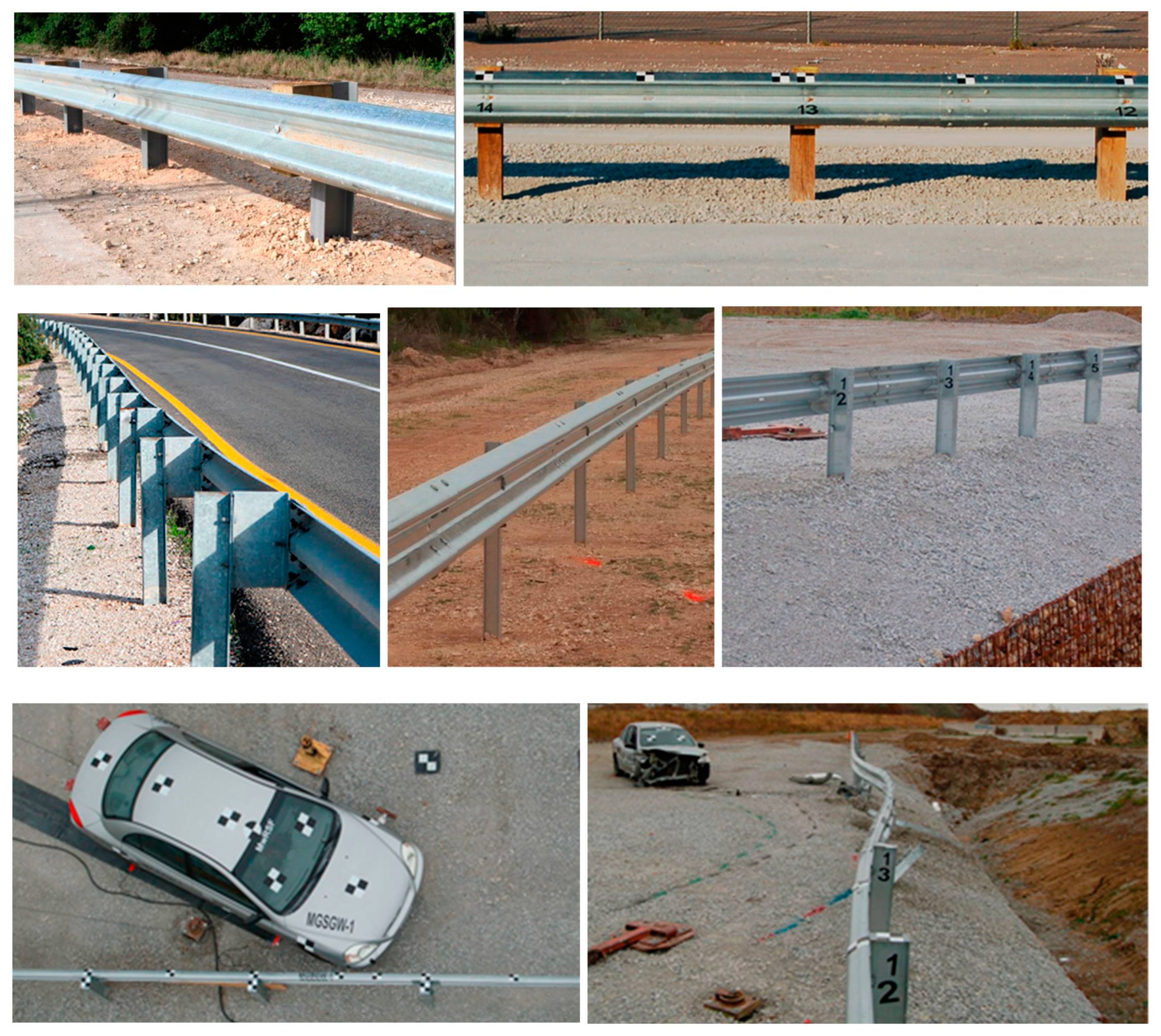
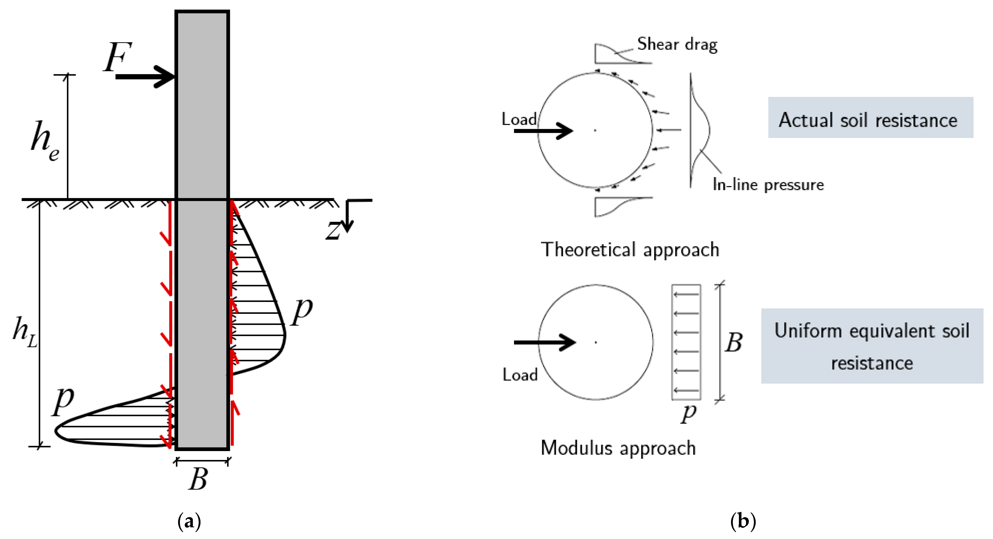
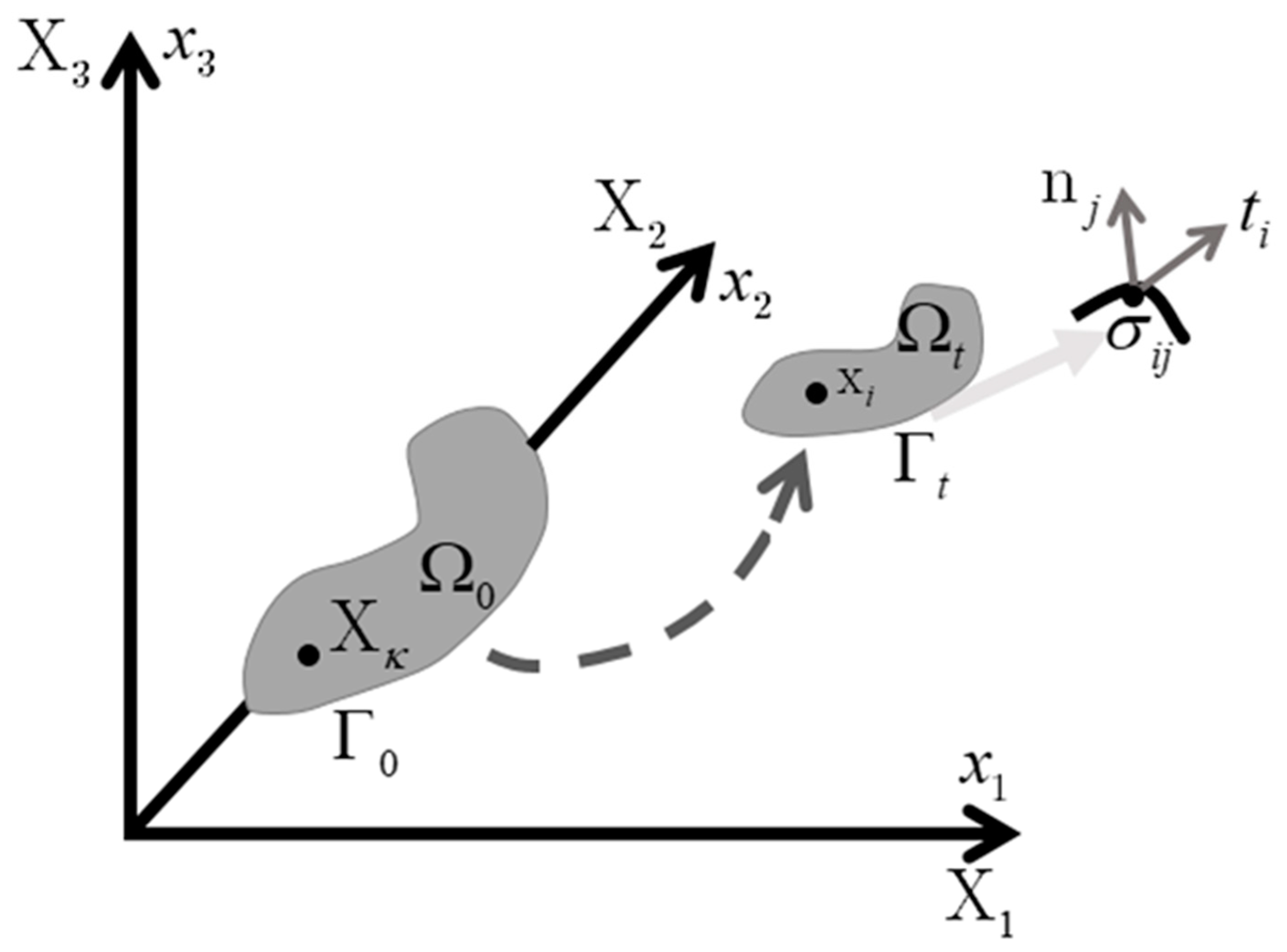
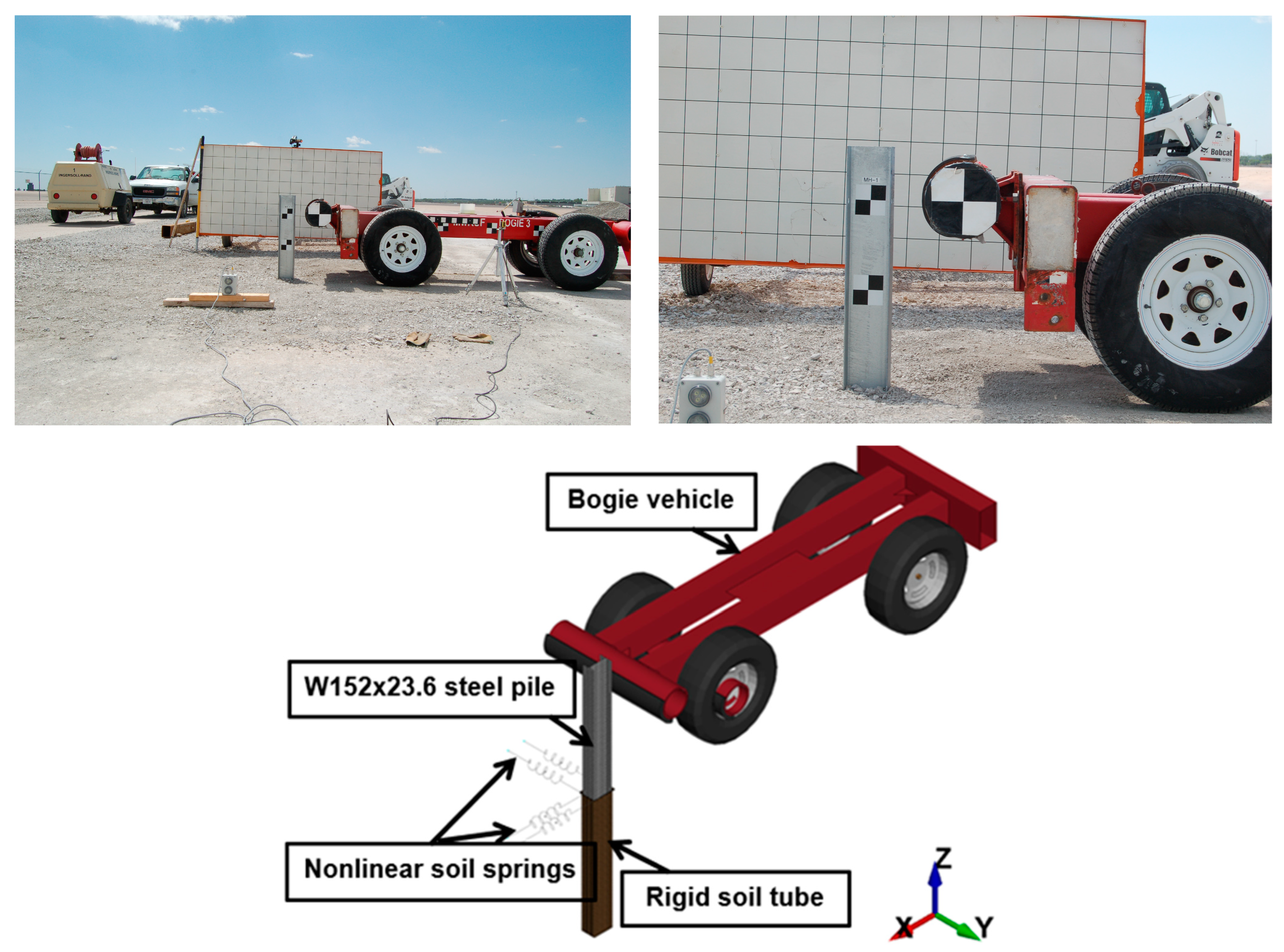
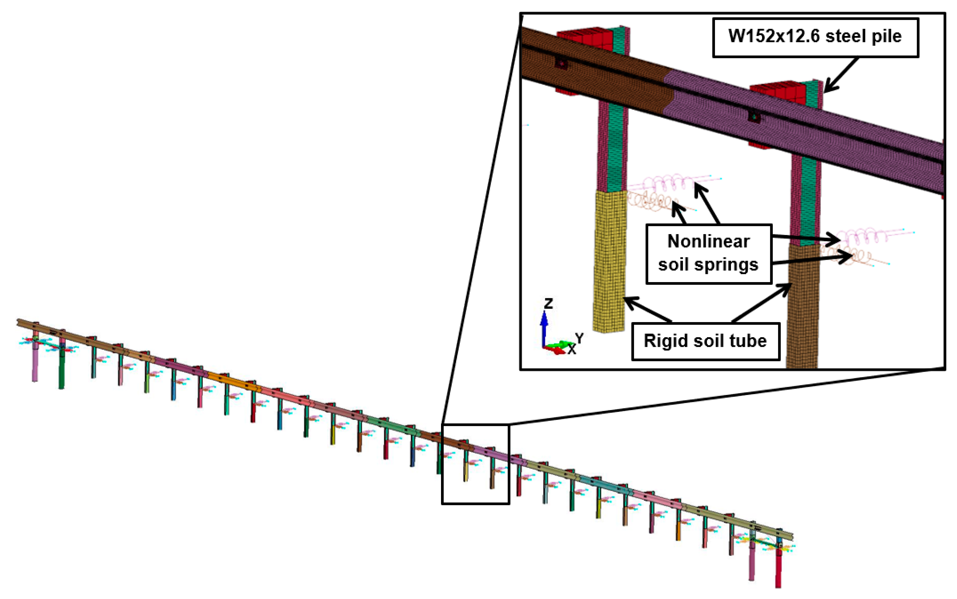
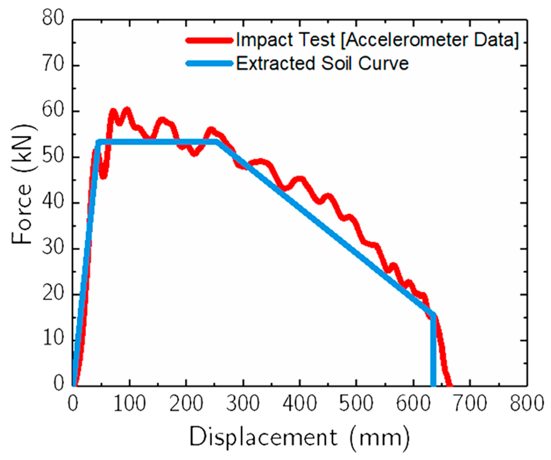
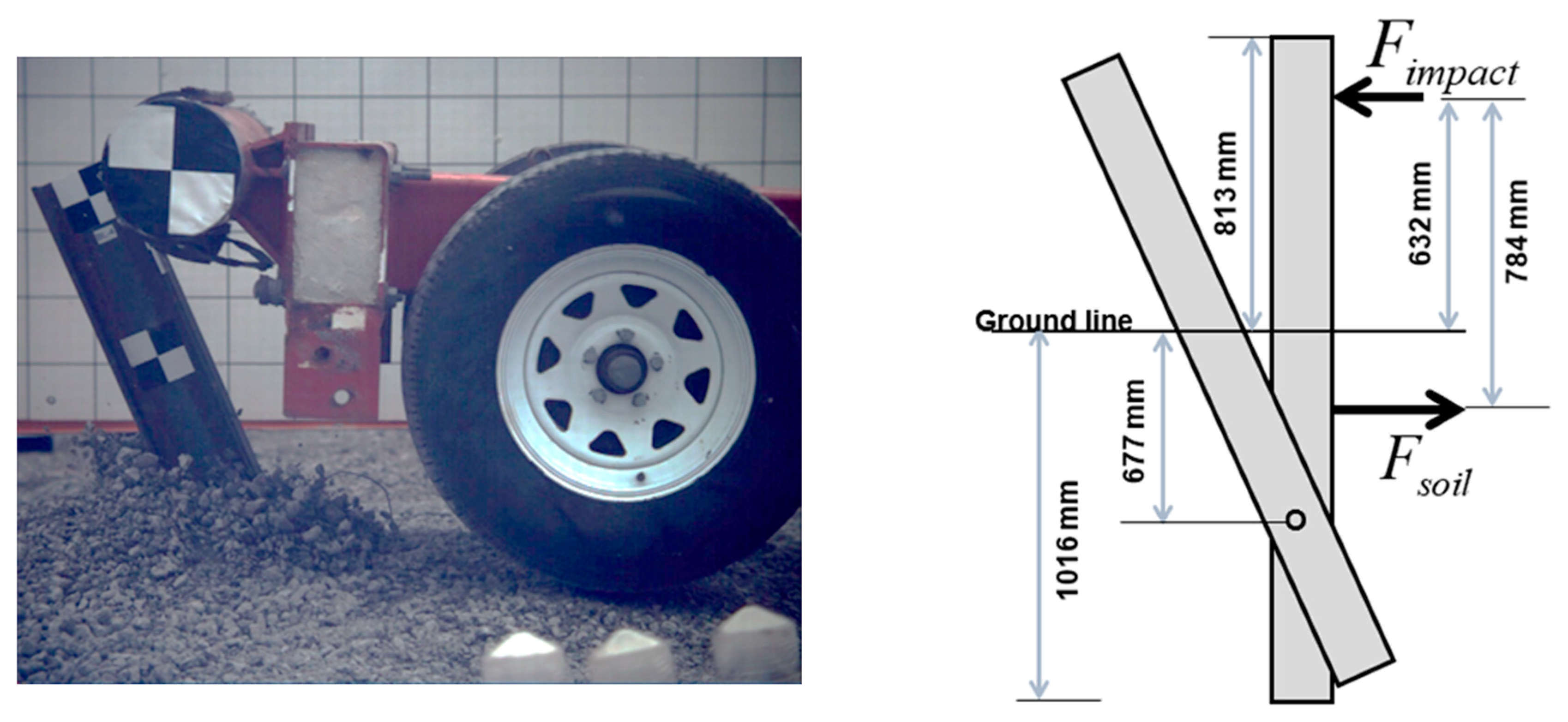
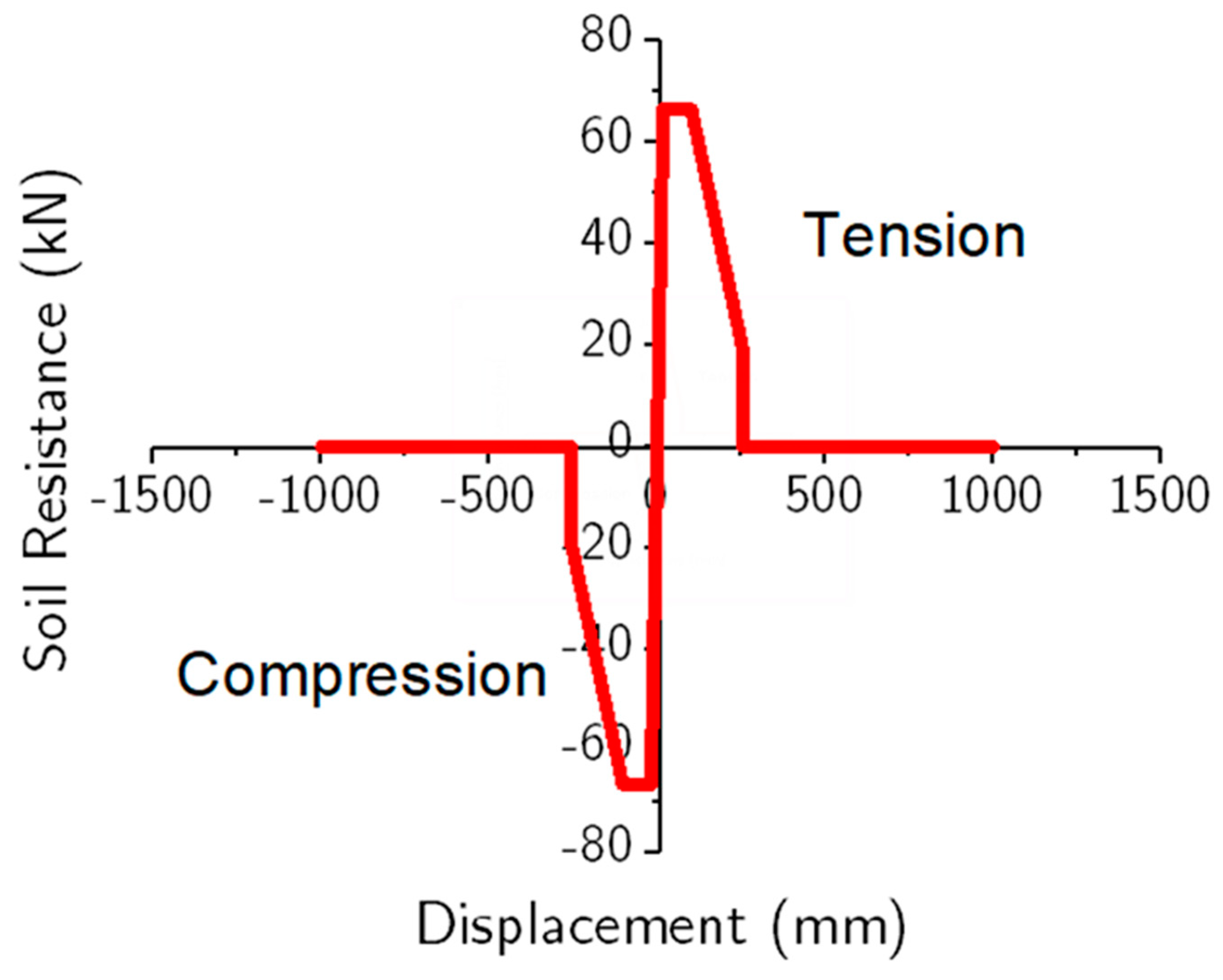
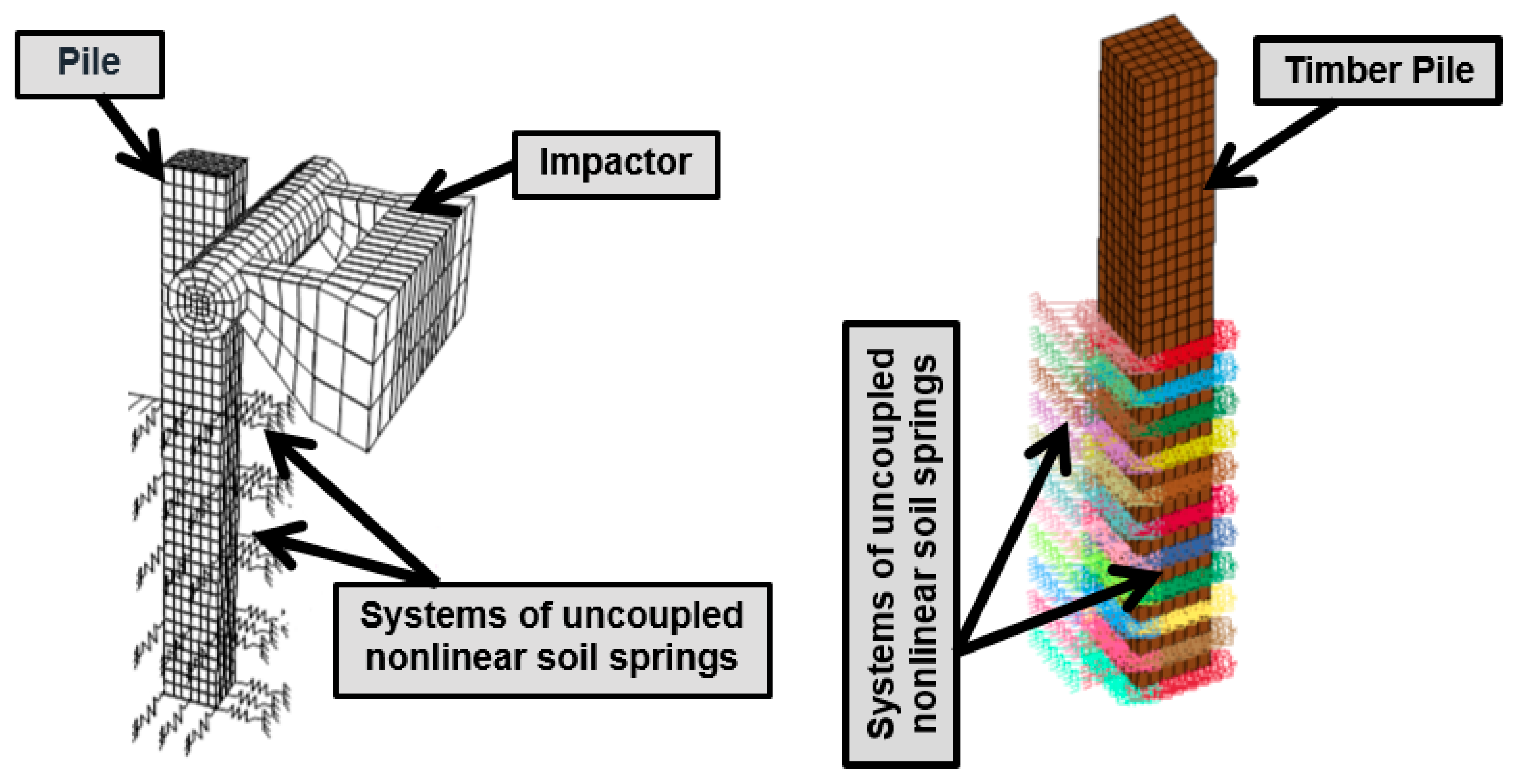
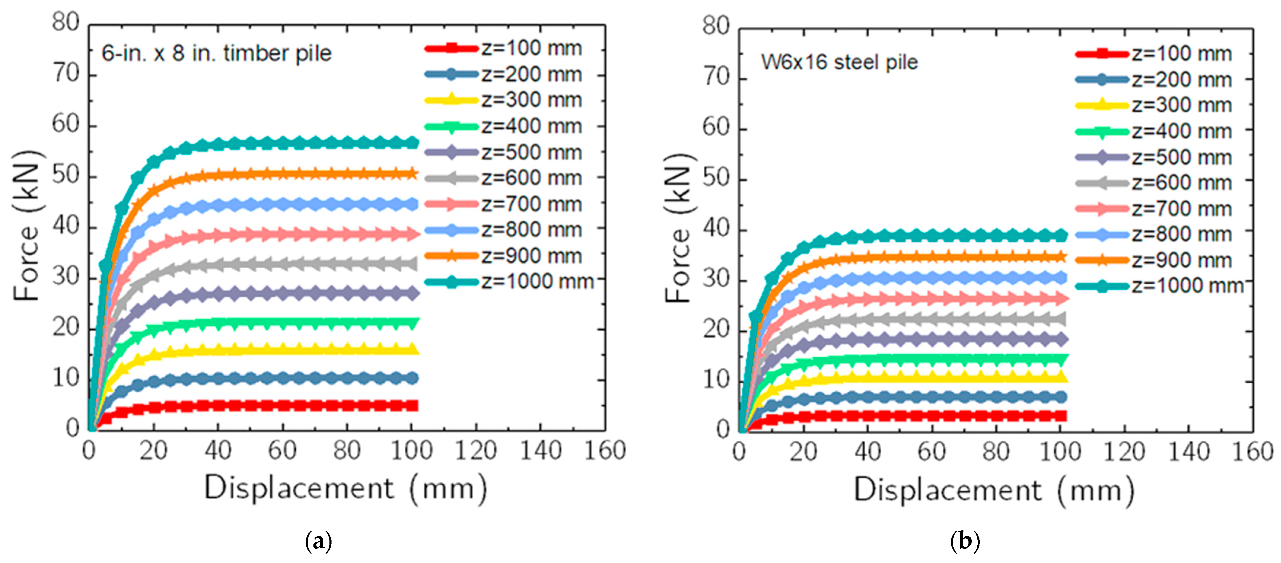
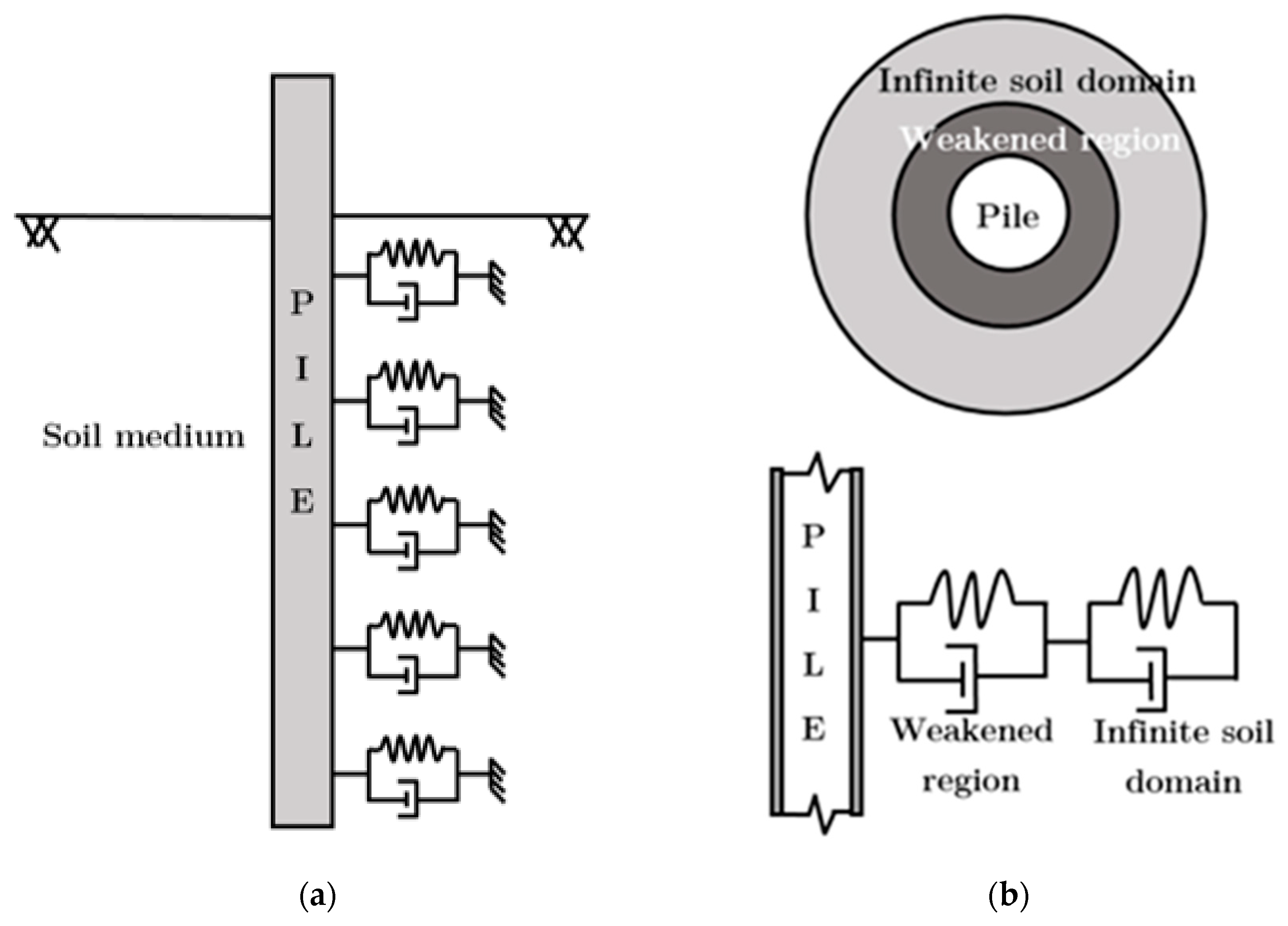
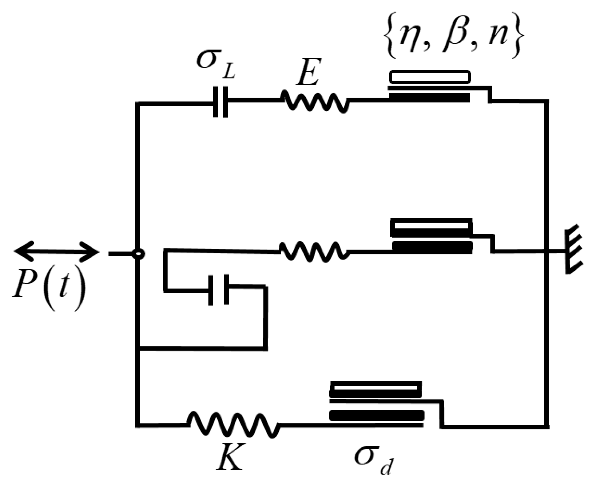
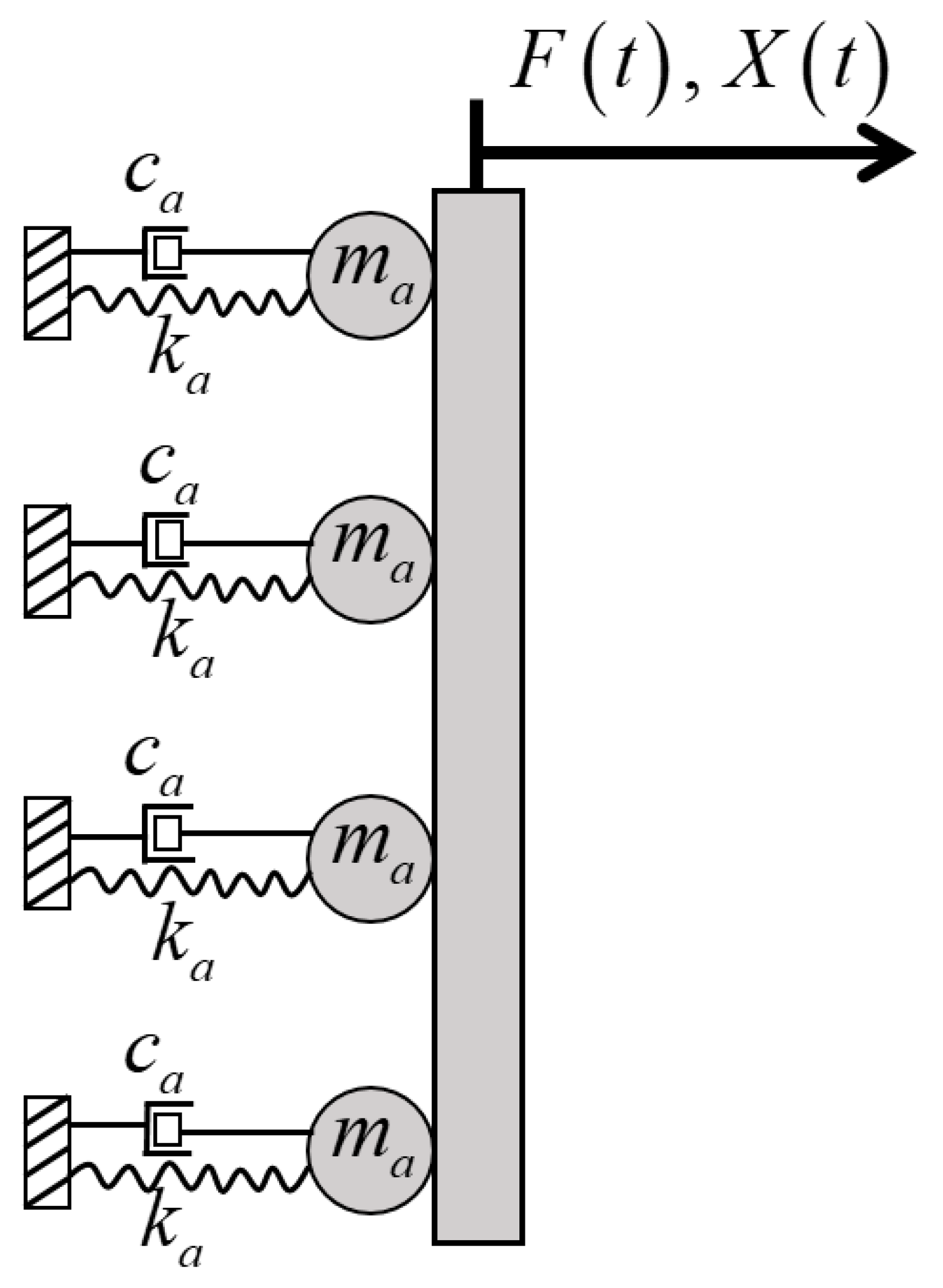
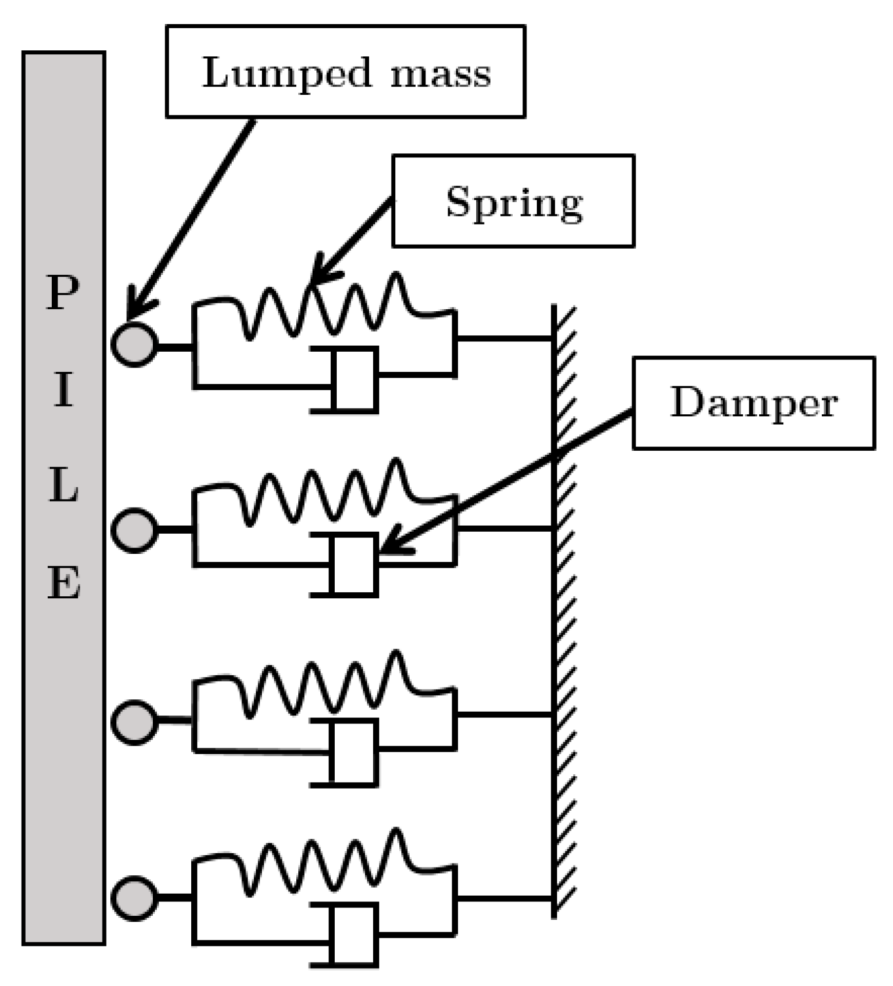
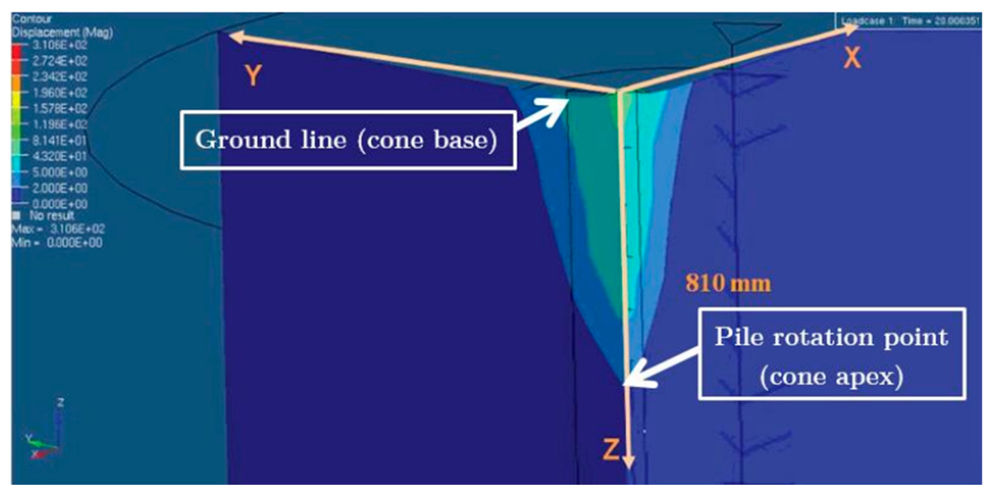
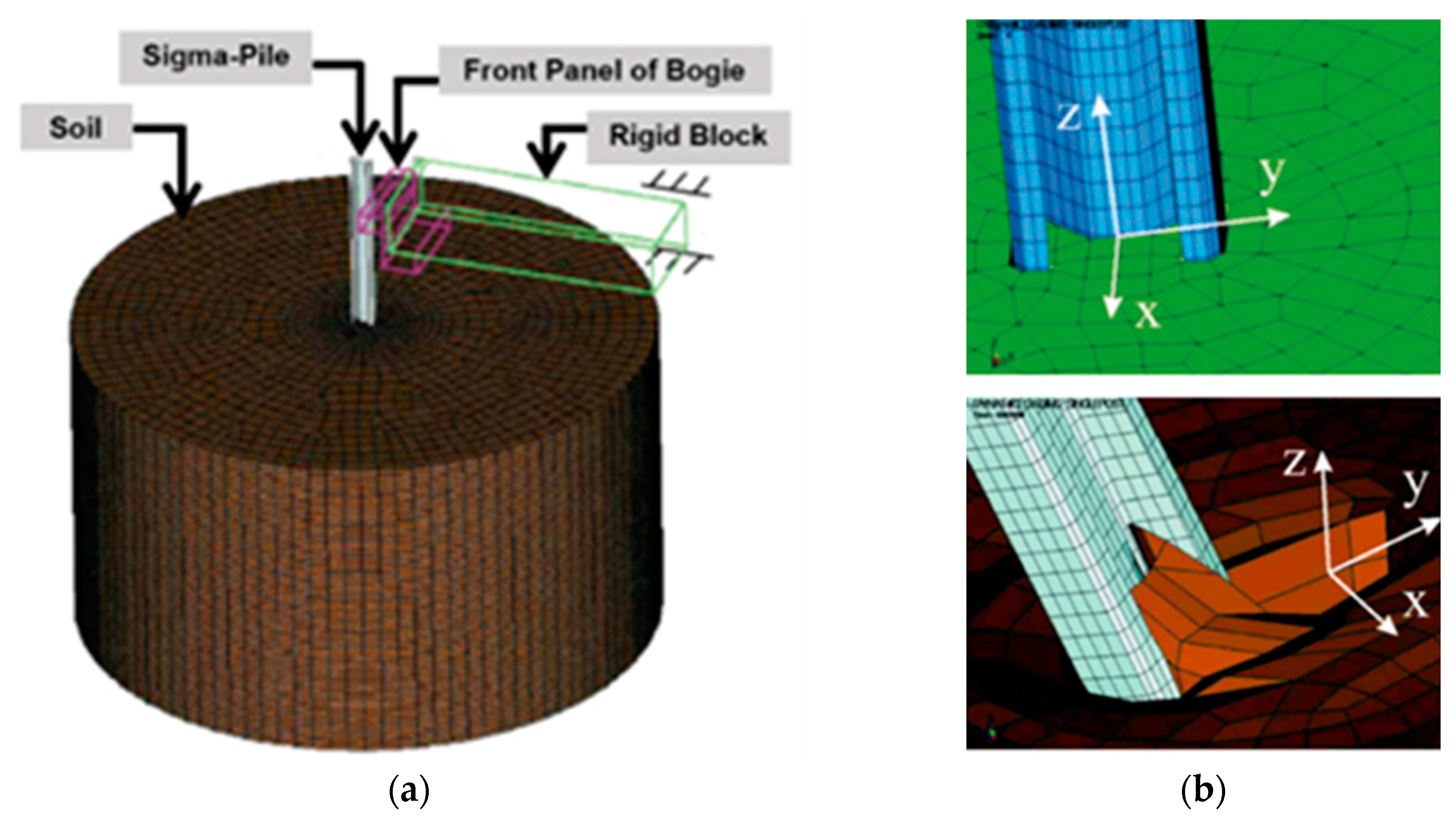
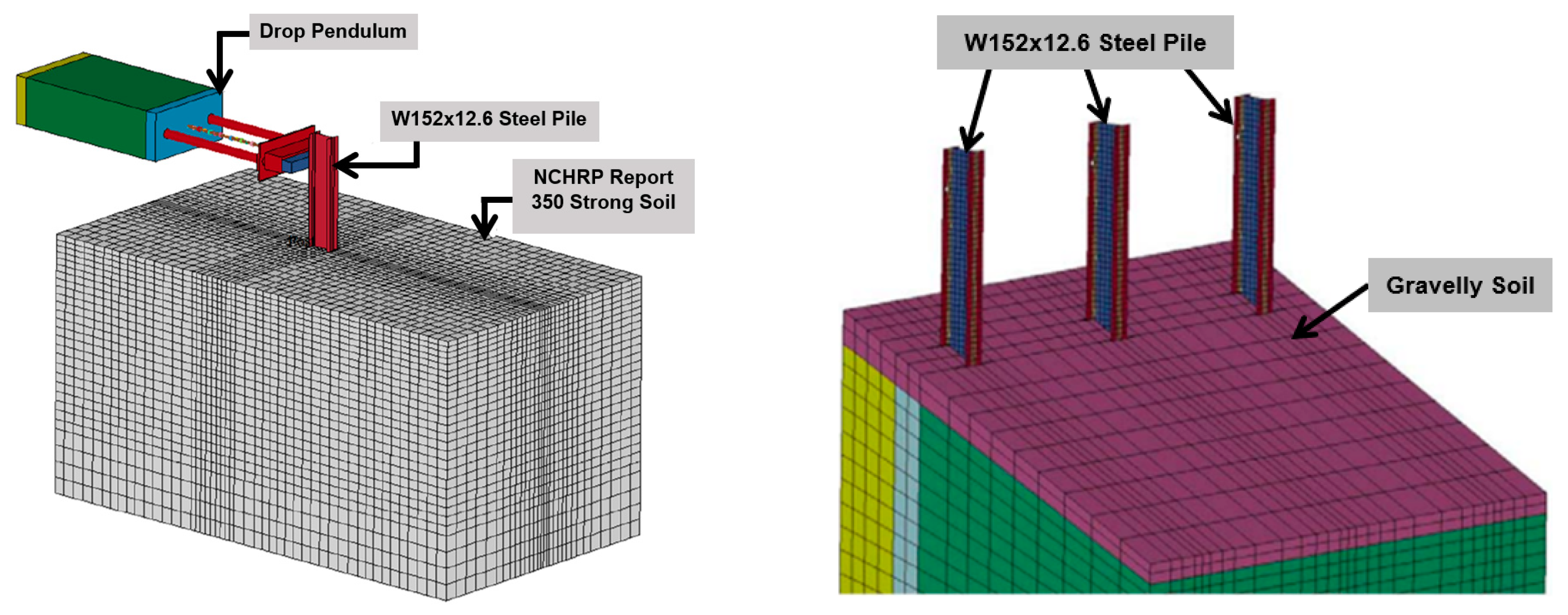
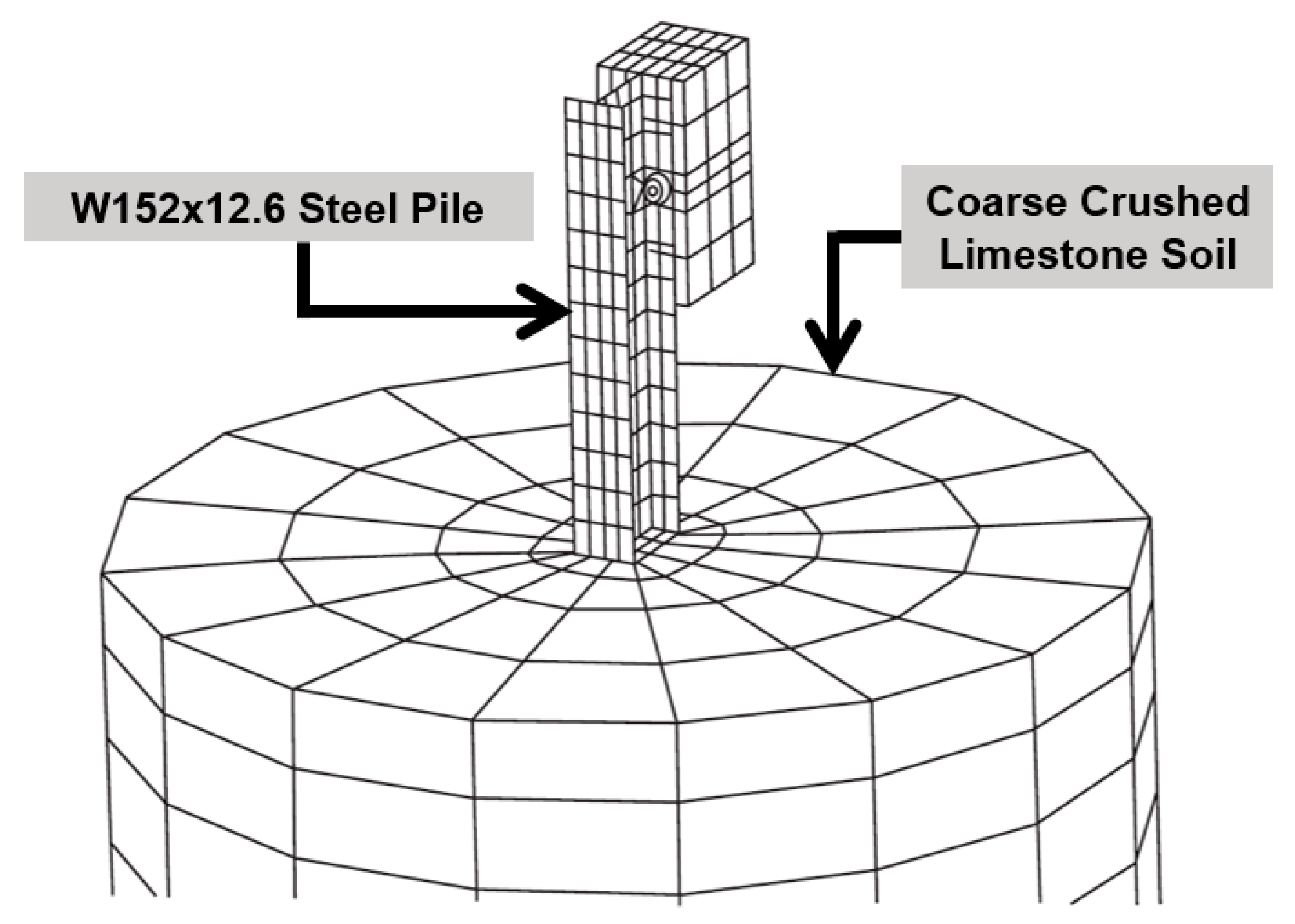
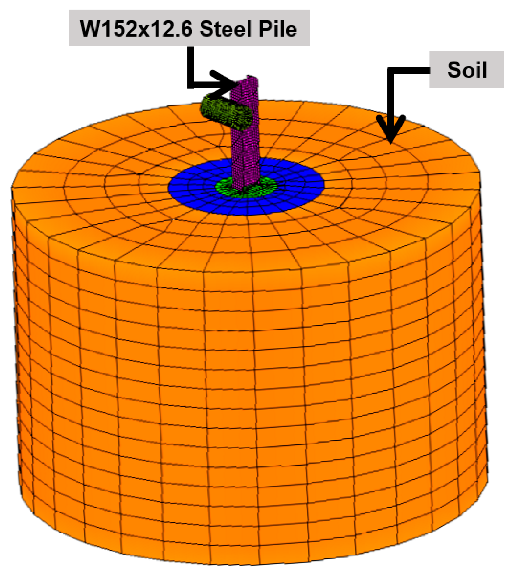


