
Seismic Behavior of Retaining Walls: A Critical Review of Analytical and Field Performance Studies


Abstract
:1. Introduction
2. Analytical Studies
2.1. Limit–State Methods

2.2. Elastic Methods
2.3. Hybrid Methods
3. Field Performance Studies
4. Conclusions
Author Contributions
Funding
Data Availability Statement
Conflicts of Interest
References
- Kramer, S.L. Geotechnical Earthquake Engineering; Prentice Hall: Englewood Cliffs, NJ, USA, 1996; pp. 1–673. [Google Scholar]
- Okabe, S. General theory on earth pressure and seismic stability of retaining wall and dam. J. Jpn. Soc. Civ. Eng. 1924, 10, 1277–1323. [Google Scholar]
- Mononobe, N.; Matsuo, H. On the determination of earth pressure during earthquake. In Proceedings of the World Engineering Conference, Tokyo, Japan; 1929; Volume 9, pp. 177–185. [Google Scholar]
- Steedman, R.S.; Zeng, X. The influence of phase on the calculation of pseudo-static earth pressure on a retaining wall. Geotechnique 1990, 40, 103–112. [Google Scholar] [CrossRef]
- Choudhury, D.; Nimbalkar, S. Seismic passive resistance by pseudo-dynamic method. Geotechnique 2005, 55, 699–702. [Google Scholar] [CrossRef]
- Choudhury, D.; Nimbalkar, S.S. Pseudo-dynamic approach of seismic active earth pressure behind retaining wall. Geotech. Geol. Eng. 2006, 24, 1103–1113. [Google Scholar] [CrossRef]
- Ghosh, P. Seismic passive earth pressure behind non-vertical retaining wall using pseudo-dynamic analysis. Geotech. Geol. Eng. 2007, 25, 693–703. [Google Scholar] [CrossRef]
- Ghosh, P. Seismic active earth pressure behind a nonvertical retaining wall using pseudo-dynamic analysis. Can. Geotech. J. 2008, 45, 117–123. [Google Scholar] [CrossRef]
- Kolathayar, S.; Ghosh, P. Seismic active earth pressure on walls with bilinear backface using pseudo-dynamic approach. Comput. Geotech. 2009, 36, 1229–1236. [Google Scholar] [CrossRef]
- Ghosh, S. Pseudo-dynamic active force and pressure behind battered retaining wall supporting inclined backfill. Soil Dyn. Earthq. Eng. 2010, 30, 1226–1232. [Google Scholar] [CrossRef]
- Basha, B.M.; Babu, G.L. Seismic rotational displacements of gravity walls by pseudodynamic method with curved rupture surface. Int. J. Geomech. 2010, 10, 93–105. [Google Scholar] [CrossRef]
- Ghanbari, A.; Ahmadabadi, M. Pseudo-dynamic active earth pressure analysis of inclined retaining walls using horizontal slices method. Sci. Iran. 2010, 17, 118–130. [Google Scholar]
- Wang, K.H.; Ma, S.J.; Wu, W.B. Pseudo-dynamic analysis of overturning stability of retaining wall. J. Cent. South Univ. Technol. 2011, 18, 2085–2090. [Google Scholar] [CrossRef]
- Bellezza, I. A new pseudo-dynamic approach for seismic active soil thrust. Geotech. Geol. Eng. 2014, 32, 561–576. [Google Scholar] [CrossRef]
- Mylonakis, G.; Kloukinas, P.; Papantonopoulos, C. An alternative to the Mononobe-Okabe equations for seismic earth pressures. Soil Dyn. Earthq. Eng. 2007, 27, 957–969. [Google Scholar] [CrossRef]
- Kloukinas, P.; Mylonakis, G.; Papantonopoulos, C. Distribution of seismic earth pressures on gravity walls by wave-based stress limit analysis. In Proceedings of the Geotechnical Earthquake Engineering and Soil Dynamics IV. American Society of Civil Engineers, Sacramento, CA, USA, 18–22 May 2008; pp. 1–10. [Google Scholar] [CrossRef]
- Chen, W.F.; Liu, X.L. Limit Analysis in Soil Mechanics; Elsevier B.V.: Amsterdam, The Netherlands, 1990; p. 476. [Google Scholar]
- Yang, X.L. Upper bound limit analysis of active earth pressure with different fracture surface and nonlinear yield criterion. Theor. Appl. Fract. Mech. 2007, 47, 46–56. [Google Scholar] [CrossRef]
- Li, X.; Wu, Y.; He, S. Seismic stability analysis of gravity retaining walls. Soil Dyn. Earthq. Eng. 2010, 30, 875–878. [Google Scholar] [CrossRef]
- Lancellotta, R. Analytical solution of passive earth pressure. Géotechnique 2002, 52, 617–619. [Google Scholar] [CrossRef]
- Lancellotta, R. Lower-bound approach for seismic passive earth resistance. Géotechnique 2007, 57, 319–321. [Google Scholar] [CrossRef]
- Pantelidis, L. The generalized coefficients of earth pressure: A unified approach. Appl. Sci. 2019, 9, 5291. [Google Scholar] [CrossRef]
- Pantelidis, L.; Christodoulou, P. Comparing Eurocode 8-5 and AASHTO Methods for Earth Pressure Analysis against Centrifuge Tests, Finite Elements, and the Generalized Coefficients of Earth Pressure. Research Square 2022, 3, 1–52. Available online: https://www.researchsquare.com/article/rs-1808466/v3 (accessed on 21 November 2023).
- Choudhury, D.; Sitharam, T.G.; Subba Rao, K.S. Seismic design of earth-retaining structures and foundations. Curr. Sci. 2004, 87, 1417–1425. [Google Scholar]
- Shamsabadi, A.; Xu, S.Y.; Taciroglu, E. A generalized log-spiral-Rankine limit equilibrium model for seismic earth pressure analysis. Soil Dyn. Earthq. Eng. 2013, 49, 197–209. [Google Scholar] [CrossRef]
- Dey, A.K.; Dey, A.; Sukladas, S. 3N formulation of the horizontal slice method in evaluating pseudostatic method for analysis of seismic active earth pressure. Int. J. Geomech. 2017, 17, 04016037. [Google Scholar] [CrossRef]
- Qu, H.l.; Deng, Y.y.; Gao, Y.n.; Huang, X.; Zhang, Z. Time history of seismic earth pressure response from gravity retaining wall based on energy dissipation. J. Mt. Sci. 2022, 19, 578–590. [Google Scholar] [CrossRef]
- Pain, A.; Choudhury, D.; Bhattacharyya, S. Seismic stability of retaining wall-soil sliding interaction using modified pseudo-dynamic method. Geotech. Lett. 2015, 5, 56–61. [Google Scholar] [CrossRef]
- Deng, Y.; Yan, Z.; He, N.; Chang, J.; Xuan, Y. Study on seismic amplification effect and active earth pressure of retaining wall based on pseudo-dynamic method and numerical simulation. J. Geol. Soc. India 2022, 98, 431–439. [Google Scholar] [CrossRef]
- Thiyyakkandi, S.; Shankar, P.; Neeraj, C.; Lukose, A. Active earth pressure on retaining walls with sloping backfill considering arching effect under rotation about base. Innov. Infrastruct. Solut. 2022, 7, 126. [Google Scholar] [CrossRef]
- Lew, M.; Sitar, N.; Atik, L.A. Seismic earth pressures: Fact or fiction? In Proceedings of the Earth Retention Conference 3. American Society of Civil Engineers, Washington, DC, USA, 1–4 August 2010; pp. 656–673. [Google Scholar] [CrossRef]
- Lew, M. Recent findings on seismic earth pressures. Struct. Des. Tall Spec. Build. 2012, 21, 48–65. [Google Scholar] [CrossRef]
- Al Atik, L.; Sitar, N. Seismic Earth Pressures on Cantilever Retaining Structures. J. Geotech. Geoenviron. Eng. 2010, 136, 1324–1333. [Google Scholar] [CrossRef]
- Mikola, R.G.; Candia, G.; Sitar, N. Seismic earth pressures on retaining structures and basement walls in cohesionless soils. J. Geotech. Geoenviron. Eng. 2016, 142, 04016047. [Google Scholar] [CrossRef]
- Veletsos, A.S.; Younan, A.H. Dynamic soil pressures on rigid vertical walls. Earthq. Eng. Struct. Dyn. 1994, 23, 275–301. [Google Scholar] [CrossRef]
- Wagner, N. Seismic Earth Pressure on Basement Walls with Cohesionless Backfill. Ph.D. Thesis, University of California, Berkeley, CA, USA, 2016. [Google Scholar]
- Seed, H.B.; Whitman, R.V. Design of earth retaining structures for dynamic loads. In Proceedings of the ASCE Specialty Conference on Lateral Stresses in the Ground and Design of Earth Retaining Structures, Cornell Univ., Ithaca, NY, USA, 22–24 June 1970; 1970; pp. 103–147. [Google Scholar]
- Rankine, W.J.M. On the stability of loose earth. Phil. Trans. R. Soc. London 1857, 147, 9–27. [Google Scholar] [CrossRef]
- Coulomb, C.A. Essai sur une application des règles de maximis et minimis à quelques problèmes de Statique, relatifs à l’Architecture. In Théorie des Machines Simples (Nouv. éd.), en Ayant Égard au Frottement de Leurs Parties et à la Roideur des Cordages; Nabu Press: New York, NY, USA, 1776; pp. 318–363. [Google Scholar]
- Kloukinas, P.; Mylonakis, G. Rankine solution for seismic earth pressures of L-shaped retaining walls. In Proceedings of the 5th International Conference on Earthquake Geotechnical Engineering, Santiago, Chile, 10–13 January 2011; pp. 10–13. [Google Scholar]
- Iskander, M.; Chen, Z.; Omidvar, M.; Guzman, I.; Elsherif, O. Active static and seismic earth pressure for c–ϕ soils. Soils Found. 2013, 53, 639–652. [Google Scholar] [CrossRef]
- Xu, S.Y.; Lawal, A.I.; Shamsabadi, A.; Taciroglu, E. Estimation of static earth pressures for a sloping cohesive backfill using extended Rankine theory with a composite log-spiral failure surface. Acta Geotech. 2019, 14, 579–594. [Google Scholar] [CrossRef]
- Ebeling, R.; Morrison, E.; Whitman, R.; Liam Finn, W. A Manual for Seismic Design of Waterfront Retaining Structures; Technical Report ITL-92-11; US Army Corps of Engineers: Washington, DC, USA, 1992. [Google Scholar]
- Sitar, N.; Mikola, R.G.; Candia, G. Seismically induced lateral earth pressures on retaining structures and basement walls. In Proceedings of the GeoCongress 2012, Oakland, CA, USA, 25–29 March 2012; pp. 335–358. [Google Scholar] [CrossRef]
- Kapila, I.P. Earthquake resistant design of retaining walls. In Second Symposium on Earthquake Symposium; University of Roorkee: Roorkee, India, 1962; pp. 97–108. [Google Scholar]
- Prakash, S.; Basavanna, B.M. Earth pressure distribution behind retaining wall during earthquake. In Proceedings of the 4th World Conference on Earthquake Engineering, Santiago, Chile, 13–18 January 1969; Volume 5, pp. 133–148. [Google Scholar]
- Mikola, R.G.; Sitar, N. Seismic Earth Pressures on Retaining Structures in Cohesionless Soils; Technical Report, Report No. UCB GT 13-01; University of California: Berkeley, CA, USA, 2013. [Google Scholar]
- Paultre, P. Structures en Béton Armé: Analyse et Dimensionnement, deuxième ed.; Presses Internationales Polytechnique: Montréal, QC, Canada, 2017; p. 1068. [Google Scholar]
- Richards, R.; Elms, D.G. Seismic behavior of gravity retaining walls. ASCE J. Geotech. Eng. Div. 1979, 105, 449–464. [Google Scholar] [CrossRef]
- Newmark, N.M. Effects of Earthquakes on Dams and Embankments. Géotechnique 1965, 15, 139–160. [Google Scholar] [CrossRef]
- Whitman, R.V.; Liao, S. Seismic design of gravity retaining walls. In Proceedings of the Eighth World Conference on Earthquake Engineering, San Francisco, CA, USA, 21–28 July 1984; pp. 533–540. [Google Scholar]
- Steedman, R.; Zeng, X. Rotation of large gravity walls on rigid foundations under seismic loading. In Analysis and Design of Retaining Structures against Earthquakes; ASCE: Reston, VA, USA, 1996; pp. 38–56. [Google Scholar] [CrossRef]
- Zeng, X.; Steedman, R.S. Rotating block method for seismic displacement of gravity walls. J. Geotech. Geoenviron. Eng. 2000, 126, 709–717. [Google Scholar] [CrossRef]
- Zhang, J.M.; Shamoto, Y.; Tokimatsu, K. Evaluation of earth pressure under any lateral deformation. Soils Found. 1998, 38, 15–33. [Google Scholar] [CrossRef]
- Zhang, J.M.; Shamoto, Y.; Tokimatsu, K. Seismic earth pressure theory for retaining walls under any lateral displacement. Soils Found. 1998, 38, 143–163. [Google Scholar] [CrossRef]
- Song, F.; Zhang, J. Evaluation of seismic earth pressures at the passive side. In Proceedings of the 14th World Conference on Earthquake Engineering, Beijing, China, 12–17 October 2008; Volume 8, pp. 12–17. [Google Scholar]
- Whitman, R.V. Seismic design and behavior of gravity retaining walls. In Proceedings of the ASCE Speciality Conference on Design and Performance of Earth Retaining Structures, Ithaca, NY, USA, 18–21 June 1990; pp. 817–834. [Google Scholar]
- Bray, J.D.; Travasarou, T.; Zupan, J. Seismic displacement design of earth retaining structures. In Proceedings of the Earth Retention Conference 3, Reston, VA, USA, 1–4 August 2010; pp. 638–655. [Google Scholar] [CrossRef]
- Pain, A.; Choudhury, D.; Bhattacharyya, S. Computation of the rotational displacements of gravity retaining walls by the pseudo-dynamic method. In Geo-China 2016: Advances in Numerical and Experimental Analysis of Transportation Geomaterials and Geosystems for Sustainable Infrastructure; ASCE: Reston, VA, USA, 2016; pp. 124–132. [Google Scholar]
- Candia, G.; Sitar, N. Seismic Earth Pressures on Retaining Structures in Cohesive Soils; Technical Report, Report No. UCB GT 13-02; University of California: Berkeley, CA, USA, 2013. [Google Scholar]
- Prakash, S.; Saran, S. Static and dynamic earth pressures behind retaining walls. In Proceedings of the Third Symposium on Earthquake Engineering, University of Roorkee, Roorkee, India, 4–6 November 1966; Volume 1, pp. 277–288. [Google Scholar]
- Saran, S.; Prakash, S. Dimensionless parameters for static and dynamic earth pressures behind retaining walls. Indian Geotech. J. 1968, 7, 295–310. [Google Scholar]
- Das, B.M.; Puri, V.K. Static and dynamic active earth pressure. Geotech. Geol. Eng. 1996, 14, 353–366. [Google Scholar] [CrossRef]
- Rao, K.S.S.; Choudhury, D. Seismic passive earth pressures in soils. J. Geotech. Geoenviron. Eng. 2005, 131, 131–135. [Google Scholar] [CrossRef]
- Shukla, S.K.; Gupta, S.K.; Sivakugan, N. Active earth pressure on retaining wall for c-ϕ soil backfill under seismic loading condition. J. Geotech. Geoenviron. Eng. 2009, 135, 690–696. [Google Scholar] [CrossRef]
- Ghosh, S.; Sengupta, S. Formulation of seismic active earth pressure of inclined retaining wall supporting c-ϕ backfill. In Proceedings of the 2012 IACSIT Coimbatore Conferences, Coimbatore, India, 18–19 February 2012; Volume 28, pp. 208–212. [Google Scholar]
- Richards, R.; Shi, X. Seismic lateral pressures in soils with cohesion. J. Geotech. Eng. 1994, 120, 1230–1251. [Google Scholar] [CrossRef]
- Anderson, D.G.; Martin, G.R.; Lam, I.P.; Wang, J.N. Seismic Analysis and Design of Retaining Walls, Buried Structures, Slopes, and Embankments; Technical Report; The National Academies Press: Washington, DC, USA, 2008. [Google Scholar] [CrossRef]
- Shukla, S.K.; Bathurst, R.J. An analytical expression for the dynamic active thrust from c-ϕ soil backfill on retaining walls with wall friction and adhesion. Geomech. Eng. 2012, 4, 209–218. [Google Scholar] [CrossRef]
- Krabbenhoft, K. Static and seismic earth pressure coefficients for vertical walls with horizontal backfill. Soil Dyn. Earthq. Eng. 2018, 104, 403–407. [Google Scholar] [CrossRef]
- Choudhury, D.; Katdare, A.D.; Shukla, S.K.; Basha, B.M.; Ghosh, P. Seismic behaviour of retaining structures, design issues and requalification techniques. Indian Geotech. J. 2014, 44, 167–182. [Google Scholar] [CrossRef]
- Matsuo, H.; Ohara, S. Lateral earth pressure and stability of quay walls during earthquakes. In Proceedings of the 2nd World Conference on Earthquake Engineering, Kyoto, Japan, 11–18 July 1960; pp. 165–181. [Google Scholar]
- Scott, R.F. Earthquake-induced earth pressures on retaining walls. In Proceedings of the Fifth World Conference on Earthquake Engineering, Rome, Italy, 25–29 June 1973; Volume 2, pp. 1611–1620. [Google Scholar]
- Wood, J.H. Earthquake-Induced Soil Pressures on Structures. Ph.D. Thesis, California Institute of Technology, Pasadena, CA, USA, 1973. [Google Scholar]
- Nazarian, H.N.; Hadjian, A.H. Earthquake-induced lateral soil pressures on structures. J. Geotech. Eng. Div. ASCE 1979, 105, 1049–1066. [Google Scholar] [CrossRef]
- Arias, A.; Sanchez-Sesma, F.J.; Ovando-Shelley, E. A simplified elastic model for seismic analysis of earth retaining structures with limited displacements. In Proceedings of the International Conferences on Recent Advances in Geotechnical Earthquake Engineering and Soil Dynamics, St. Louis, MO, USA; 1981; Volume 1, pp. 235–240. [Google Scholar]
- Veletsos, A.S.; Younan, A.H. Dynamic modeling and response of soil-wall systems. J. Geotech. Eng. 1994, 120, 2155–2179. [Google Scholar] [CrossRef]
- Veletsos, A.S.; Younan, A.H. Dynamic response of cantilever retaining walls. J. Geotech. Geoenviron. Eng. 1997, 123, 161–172. [Google Scholar] [CrossRef]
- Psarropoulos, P.N.; Klonaris, G.; Gazetas, G. Seismic earth pressures on rigid and flexible retaining walls. Soil Dyn. Earthq. Eng. 2005, 25, 795–809. [Google Scholar] [CrossRef]
- Giarlelis, C.; Mylonakis, G. Interpretation of dynamic retaining wall model tests in light of elastic and plastic solutions. Soil Dyn. Earthq. Eng. 2011, 31, 16–24. [Google Scholar] [CrossRef]
- Richards, R.; Huang, C.; Fishman, K.L. Seismic earth pressure on retaining structures. J. Geotech. Geoenviron. Eng. 1999, 125, 771–778. [Google Scholar] [CrossRef]
- Li, X. Dynamic analysis of rigid walls considering flexible foundation. J. Geotech. Geoenviron. Eng. 1999, 125, 803–806. [Google Scholar] [CrossRef]
- Wu, G.; Finn, W.D.L. Seismic pressures against rigid walls. In Proceedings of the Analysis and Design of Retaining Structures against Earthquakes, Washington, DC, USA, 10–14 November 1996; pp. 1–18. [Google Scholar] [CrossRef]
- Wu, G.; Finn, W.L. Seismic lateral pressures for design of rigid walls. Can. Geotech. J. 1999, 36, 509–522. [Google Scholar] [CrossRef]
- Jung, C.; Bobet, A.; Fernández, G. Analytical solution for the response of a flexible retaining structure with an elastic backfill. Int. J. Numer. Anal. Methods Geomech. 2010, 34, 1387–1408. [Google Scholar] [CrossRef]
- Kloukinas, P.; Langousis, M.; Mylonakis, G. Simple wave solution for seismic earth pressures on non yielding walls. J. Geotech. Geoenviron. Eng. 2012, 138, 1514–1519. [Google Scholar] [CrossRef]
- Brandenberg, S.J.; Mylonakis, G.; Stewart, J.P. Kinematic framework for evaluating seismic earth pressures on retaining walls. J. Geotech. Geoenviron. Eng. 2015, 141, 1–10. [Google Scholar] [CrossRef]
- Brandenberg, S.J.; Mylonakis, G.; Stewart, J.P. Approximate solution for seismic earth pressures on rigid walls retaining inhomogeneous elastic soil. Soil Dyn. Earthq. Eng. 2017, 97, 468–477. [Google Scholar] [CrossRef]
- Durante, M.; Brandenberg, S.J.; Stewart, J.; Mylonakis, G. Winkler stiffness intensity for flexible walls retaining inhomogeneous soil. In Proceedings of the 5th Geotechnical Earthquake Engineering and Soil Dynamics Conference (GEESD 2018), Austin, TX, USA, 10–13 June 2018; pp. 473–482. [Google Scholar]
- Younan, A.H.; Veletsos, A.S. Dynamic response of flexible retaining walls. Earthq. Eng. Struct. Dyn. 2000, 29, 1815–1844. [Google Scholar] [CrossRef]
- Choudhury, D.; Nimbalkar, S.S.; Mandal, J.N. Comparison of Pseudo-Static and Pseudo-Dynamic Methods for Seismic Earth Pressure on Retaining Wall. J. Indian Geophys. Union 2006, 10, 263–271. [Google Scholar]
- Choudhury, D.; Nimbalkar, S.S. Seismic rotational displacement of gravity walls by pseudodynamic method. Int. J. Geomech. 2008, 8, 169–175. [Google Scholar] [CrossRef]
- Basha, B.M.; Babu, G.L. Seismic passive earth pressure coefficients by pseudo-dynamic method using composite failure mechanism. In Proceedings of the GeoCongress 2008: Geosustainability and Geohazard Mitigation, New Orleans, LA, USA, 9–12 March 2008; 2008; Volume 178, pp. 343–350. [Google Scholar] [CrossRef]
- Ghosh, S.; Sharma, R.P. Seismic active earth pressure on the back of battered retaining wall supporting inclined backfill. Int. J. Geomech. 2012, 12, 54–63. [Google Scholar] [CrossRef]
- Choudhury, D.; Katdare, A.D.; Pain, A. New method to compute seismic active earth pressure on retaining wall considering seismic waves. Geotech. Geol. Eng. 2014, 32, 391–402. [Google Scholar] [CrossRef]
- Nimbalkar, S.; Pain, A.; Ahmad, S.M.; Chen, Q. Stability assessment of earth retaining structures under static and seismic conditions. Infrastructures 2019, 4, 15. [Google Scholar] [CrossRef]
- Choudhury, D.; Nimbalkar, S. Seismic rotational displacement of gravity walls by pseudo-dynamic method: Passive case. Soil Dyn. Earthq. Eng. 2007, 27, 242–249. [Google Scholar] [CrossRef]
- Ahmad, S.M.; Choudhury, D. Pseudo-dynamic approach of seismic design for waterfront reinforced soil-wall. Geotext. Geomembr. 2008, 26, 291–301. [Google Scholar] [CrossRef]
- Ahmad, S.M.; Choudhury, D. Stability of waterfront retaining wall subjected to pseudo-dynamic earthquake forces and tsunami. J. Earthq. Tsunami 2008, 2, 107–131. [Google Scholar] [CrossRef]
- Ahmad, S.M.; Choudhury, D. Seismic design factor for sliding of waterfront retaining wall. Proc. Inst. Civ. Eng. Geotech. Eng. 2009, 162, 269–276. [Google Scholar] [CrossRef]
- Choudhury, D.; Ahmad, S.M. Stability of waterfront retaining wall subjected to pseudo-static earthquake forces. Ocean. Eng. 2007, 34, 1947–1954. [Google Scholar] [CrossRef]
- Nimbalkar, S.S.; Choudhury, D.; Mandal, J. Seismic stability of reinforced-soil wall by pseudo-dynamic method. Geosynth. Int. 2006, 13, 111–119. [Google Scholar] [CrossRef]
- Nimbalkar, S.; Choudhury, D. Sliding stability and seismic design of retaining wall by pseudo-dynamic method for passive case. Soil Dyn. Earthq. Eng. 2007, 27, 497–505. [Google Scholar] [CrossRef]
- Azuma, H.; Amano, R.; Ishii, Y. Aseismic design of quay walls in Japan by Ryōkichi Amano. In Proceedings of the First World Conference on Earthquake Engineering, Berkeley, CA, USA, 1–5 June 1956. [Google Scholar]
- Duke, C.M.; Leeds, D.J. Response of soils, foundations, and earth structures to the Chilean earthquakes of 1960. Bull. Seismol. Soc. Am. 1963, 53, 309–357. [Google Scholar] [CrossRef]
- Hayashi, S.; Kubo, K.; Nakase, A. Damage to harbour structures by the Niigata earthquake. Soils Found. 1966, 6, 89–112. [Google Scholar] [CrossRef]
- Inagaki, H.; Iai, S.; Sugano, T.; Yamazaki, H.; Inatomi, T. Performance of caisson type quay walls at kobe port. Soils Found. 1996, 36, 119–136. [Google Scholar] [CrossRef] [PubMed]
- Clough, G.; Fragaszy, R. A Study of Earth Loadings on Floodway Retaining Structures in the 1971 San Fernando Valley Earthquake. In Proceedings of the Sixth World Conference on Earthquake Engineering, New Delhi, India, 10–14 January 1977; Volume 3. [Google Scholar]
- Benuska, K.L. Ground motion, Loma Prieta earthquake reconnaissance report. Earthq. Spectra 1990, 6, 25–80. [Google Scholar]
- Whitman, R.V. Seismic design of earth retaining structures. In Proceedings of the International Conferences on Recent Advances in Geotechnical Earthquake Engineering and Soil Dynamics, St. Louis, MO, USA, 11–15 March 1991; p. 14. [Google Scholar]
- Stewart, J.P.; Bray, J.D.; Seed, R.B.; Sitar, N. Preliminary report on the principal geotechnical aspects of the January 17, 1994 Northridge earthquake; Rpt. No. UCB/EERC-94/08; Earthquake Engineering Research Center, University of California: Berkeley, CA, USA, 1994. [Google Scholar]
- Hall, J.F. Northridge Earthquake of January 17, 1994 Reconnaissance Report—Volume 1; Technical Report, Earthquake Spectra; Earthquake Engineering Research Institute: Oakland, CA, USA, 1995; Volume 11. [Google Scholar]
- Holmes, W.T.; Somers, P. Northridge Earthquake of January 17, 1994 Reconnaissance Report—Volume 2; Technical Report, Earthquake Spectra; Earthquake Engineering Research Institute: Oakland, CA, USA, 1996; Volume 11. [Google Scholar]
- Lew, M.; Simantob, E.; Hudson, M. Performance of shored earth retaining systems during the January 17, 1994 Northridge earthquake. In Proceedings of the International Conferences on Recent Advances in Geotechnical Earthquake Engineering and Soil Dynamics, St. Louis, MO, USA, 2–7 April 1995; Volume 3, pp. 1417–1422. [Google Scholar]
- Koseki, J.; Tatsuoka, F.; Munaf, Y.; Tateyama, M.; Kojima, K. A modified procedure to evaluate active earth pressure at high seismic loads. Soils Found. 1998, 38, 209–216. [Google Scholar] [CrossRef]
- Gazetas, G.; Psarropoulos, P.; Anastasopoulos, I.; Gerolymos, N. Seismic behaviour of flexible retaining systems subjected to short-duration moderately strong excitation. Soil Dyn. Earthq. Eng. 2004, 24, 537–550. [Google Scholar] [CrossRef]
- Lew, M.; Sitar, N.; Atik, L.A.; Pourzanjani, M.; Hudson, M.B. Seismic earth pressures on deep building basements. In Proceedings of the Annual Convention of Structural Engineers Association of California, Indian Wells, CA, USA, 22–25 September 2010; pp. 1–12. [Google Scholar]
- Iida, H.; Hiroto, T.; Yoshida, N.; Iwafuji, M. Damage to daikai subway station. Soils Found. 1996, 36, 283–300. [Google Scholar] [CrossRef]
- Yoshida, N. Damage to subway station during the 1995 Hyogoken-Nambu (Kobe) earthquake. In Earthquake Geotechnical Case Histories for Performance-Based Design; CRC Press: Tokyo, Japan, 2009; pp. 373–389. [Google Scholar] [CrossRef]
- Ling, H.I.; Leshchinsky, D.; Chou, N.N. Post-earthquake investigation on several geosynthetic-reinforced soil retaining walls and slopes during the Ji-Ji earthquake of Taiwan. Soil Dyn. Earthq. Eng. 2001, 21, 297–313. [Google Scholar] [CrossRef]
- Huang, C. Investigations of soil retaining structures damaged during the Chi-Chi (Taiwan) earthquake. J. Chin. Inst. Eng. 2000, 23, 417–428. [Google Scholar] [CrossRef]
- Tokida, K.; Matsuo, O.; Nakamura, S. Damage of earth retaining structures in the 1999 Chi-Chi, Taiwan earthquake. In Proceedings of the 32nd Joint Meeting of the U.S.-Japan Cooperative Program in Natural Resources-Panel on Wind and Seismic Effects, National Institute of Standards and Technology Special Publication 963, Gaithersburg, MD, USA, 16–19 May 2000; pp. 495–512. [Google Scholar]
- Rathje, E.M.; Stewart, J.P.; Bora Baturay, M.; Bray, J.D.; Bardet, J.P. Strong ground motions and damage patterns from the 1999 Düzce earthquake in Turkey. J. Earthq. Eng. 2006, 10, 693–724. [Google Scholar] [CrossRef]
- Gur, T.; Pay, A.C.; Ramirez, J.A.; Sozen, M.A.; Johnson, A.M.; Irfanoglu, A.; Bobet, A. Performance of school buildings in Turkey during the 1999 düzce and the 2003 bingöl earthquakes. Earthq. Spectra 2009, 25, 239–256. [Google Scholar] [CrossRef]
- Bray, J.; Rollins, K.; Hutchinson, T.; Verdugo, R.; Ledezma, C.; Mylonakis, G.; Assimaki, D.; Montalva, G.; Arduino, P.; Olson, S.M.; et al. Effects of ground failure on buildings, ports, and industrial facilities. Earthq. Spectra 2012, 28, S97–S118. [Google Scholar] [CrossRef]
- Verdugo, R.; Sitar, N.; Frost, J.D.; Bray, J.D.; Candia, G.; Eldridge, T.; Hashash, Y.; Olson, S.M.; Urzua, A. Seismic performance of earth structures during the February 2010 Maule, Chile, earthquake: Dams, levees, tailings dams, and retaining walls. Earthq. Spectra 2012, 28, 75–96. [Google Scholar] [CrossRef]
- Rollins, K.; Franke, F.; Luna, R.; Rocco, N.; Avila, D.; Climent, M.A. Geotechnical Aspects of Sept. 5, 2012 M7.6 Samara, Costa Rica Earthquake; Report 031; Geotechnical Extreme Events Reconnaissance (GEER) Association: Berkeley, CA, USA, 2013; Version 1.0. [Google Scholar]
- Nikolaou, S.; Zekkos, D.; Assimaki, D.; Gilsanz, R. Earthquake Reconnaissance January 26th/ February 2nd 2014 Cephalonia, Greece Events; Geotechnical Extreme Events Reconnaissance (GEER) Report 034; GEER/EERI/ATC: Oakland, CA, USA, 2014. [Google Scholar]
- Rollins, K.; Ledezma, C.; Montalva, G. Geotechnical Aspects of April 1, 2014, M8.2 Iquique, Chile Earthquake; Report 038; Geotechnical Extreme Events Reconnaissance (GEER) Association: Berkeley, CA, USA, 2014; Version 1.2. [Google Scholar]
- Candia, G.; Ledezma, C.; Montalva, G.; Rollins, K. Geotechnical observations from the 2014 Iquique earthquake. In Proceedings of the 16th World Conference on Earthquake Engineering, Santiago, Chile, 9–13 January 2017; pp. 1–12. [Google Scholar]
- Hashash, Y.M.; Tiwari, B.; Moss, R.E.S.; Asimaki, D.; Clahan, K.B.; Kieffer, D.S.; Dreger, D.S.; Macdonald, A.; Madugo, C.M.; Mason, H.B.; et al. Geotechnical Field Reconnaissance: Gorkha (Nepal) Earthquake of April 25, 2015 and Related Shaking Sequence; Report 040; Geotechnical Extreme Event Reconnaisance (GEER) Association: Berkeley, CA, USA, 2015. [Google Scholar]
- De Pascale, G.P.; Montalva, G.; Candia, G.; Ledezma, C. Geotechnical Reconnaissance of the 2015 Mw 8.3 Illapel, Chile Earthquake Turning Disaster into Knowledge; Report 043; Geotechnical Extreme Event Reconnaisance (GEER) Association: Berkeley, CA, USA, 2015; Version 1.0. [Google Scholar] [CrossRef]
- Lanzo, G.; Tommasi, P.; Ausilio, E.; Aversa, S.; Bozzoni, F.; Cairo, R.; D’Onofrio, A.; Durante, M.G.; Foti, S.; Giallini, S.; et al. Reconnaissance of geotechnical aspects of the 2016 Central Italy earthquakes. Bull. Earthq. Eng. 2019, 17, 5495–5532. [Google Scholar] [CrossRef]
- Dashti, S.; Ganapati, N.E. Reconnaissance following the August 14, 2021 Haiti Earthquake: Perspectives from Geotechnical Engineering and Social/Political Sciences; Report 073; Geotechnical Extreme Events Reconnaissance (GEER) Association: Berkeley, CA, USA, 2021. [Google Scholar]


| Limit–State Based Methods | |
|---|---|
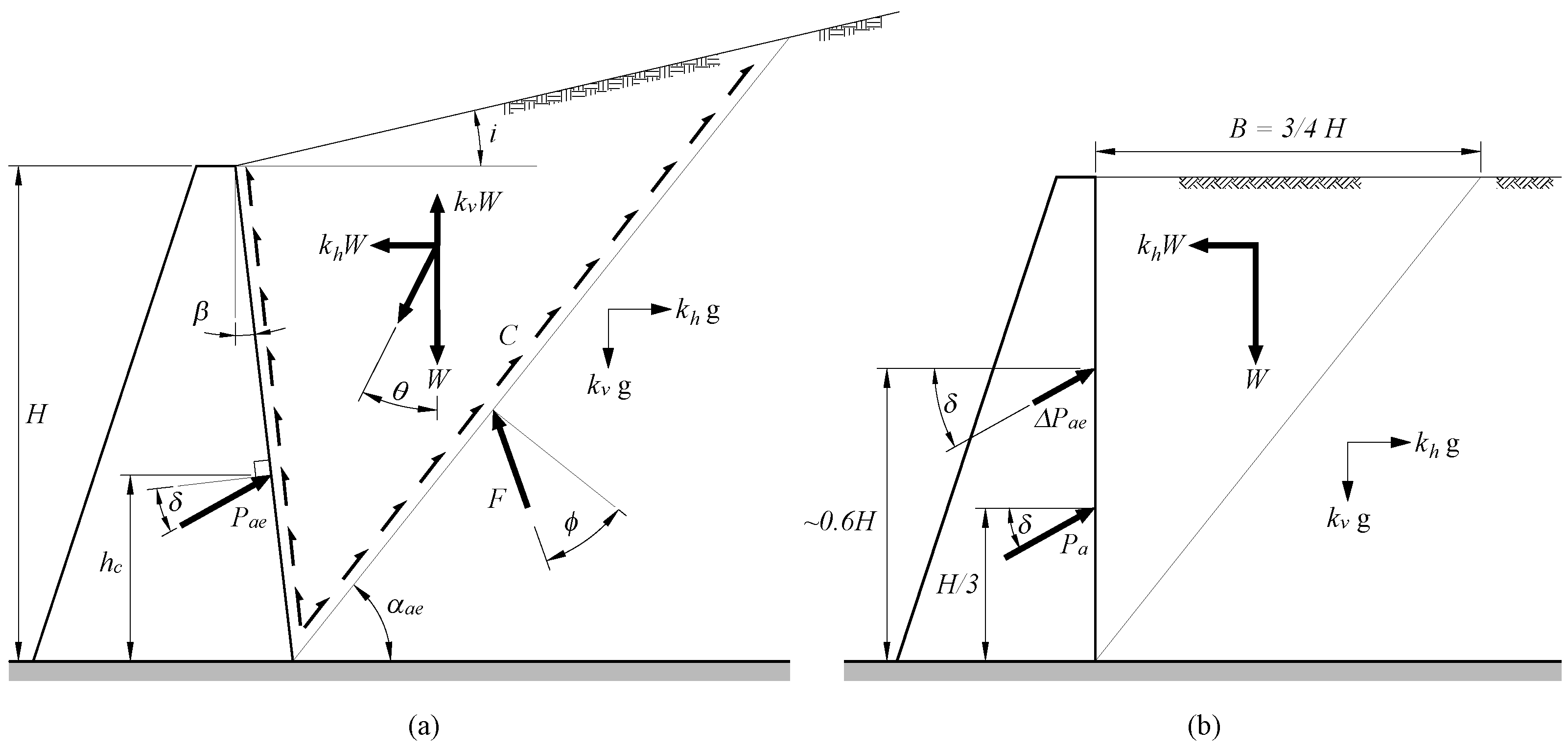
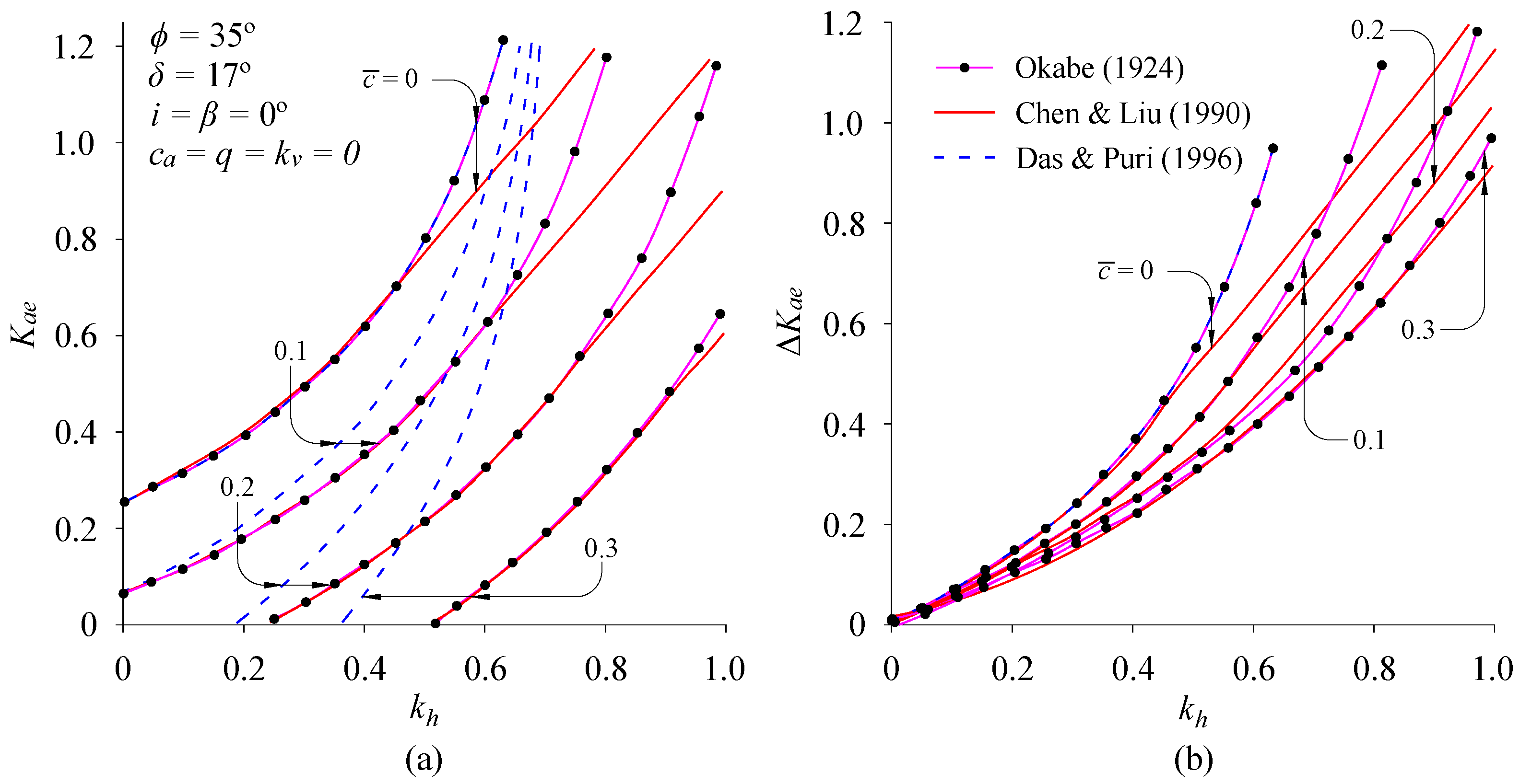
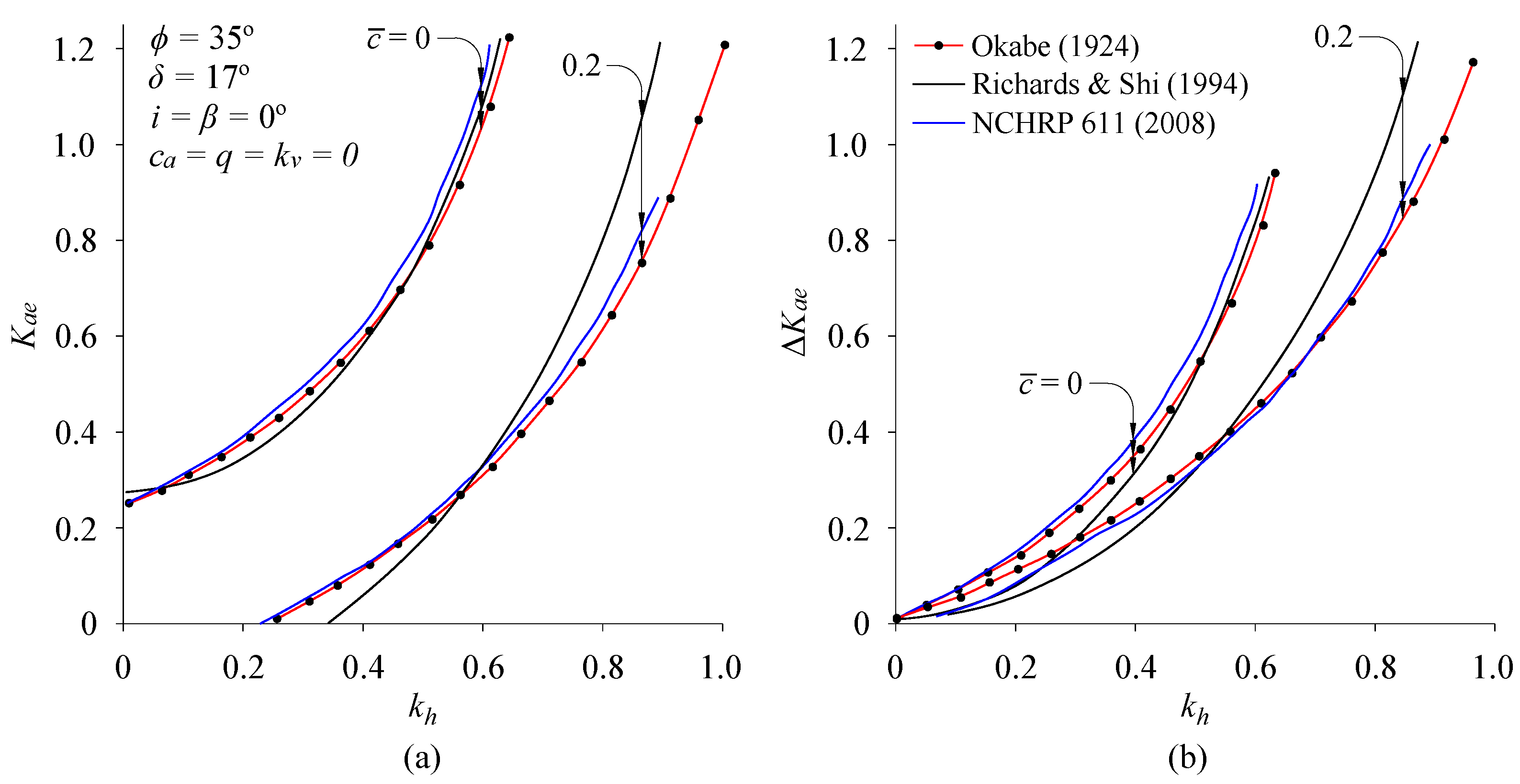
| Okabe (1924) [2]; Mononobe and Matsuo (1929) [3], | The M-O method is most widely used. Initially designed for gravity walls retaining cohesionless soil. acts at (H is the height of the wall). does not converge when < − i. |
| Seed and Whitman (1970) [37], | An extension of the M-O approach. Other aspects of the problem are comparable to the M-O approach, with the exception of a dynamic component acting at 0.6H. |
| For vertical walls and horizontal dry backfill | |
| Richards and Elms (1979) [49], | Using the Newmark [50] procedure, a method for calculating seismic- induced permanent wall displacements was proposed. Wall inertia was considered. This provides the basis for all modern design guidelines. |
| Permanent wall displacement, | |
| (Horizontal acceleration) | |
| Zhang et al. (1998) [54,55] | Based on the “intermediate wedge concept”, dynamic earth pressures under any state can be determined. The strain increment ratio is an important parameter in this concept, typically determined by cyclic triaxial testing. |
| Strain increment ratio-related method for wall pressures | |
| Zeng and Steedman (2000) [53], | Using the Newmark [50] approach, a rotating block method was devised to determine the seismic rotational displacement of gravity walls. No inertia effects were considered. |
| Rotational acceleration, | |
| Mylonakis (2007) [15], | An alternative closed-form stress plasticity solution for the M-O method for calculating total (static + dynamic) earth pressures on retaining walls with cohesionless backfills. Uniform backfill was considered in the analysis. |
| Lancellotta (2007) [21], | Lancellotta [21] developed a technique for computing seismic passive earth pressure on retaining walls using a lower-bound limit analysis approach. Wall roughness was considered. However, as with the M-O approach, this method also presents the negative root problem. |
| Anderson et al. (2008) [68], | To provide guidelines in practical design problems, a chart method for applying the M-O method to cohesive soils was developed. The use of seismic coefficient charts was suggested. However, as with the M-O approach, this method is also limited to non-homogeneous soils and intricate back-slope geometry. |
| Chart method for cohesive soils | |
| Elastic–Based Methods | |
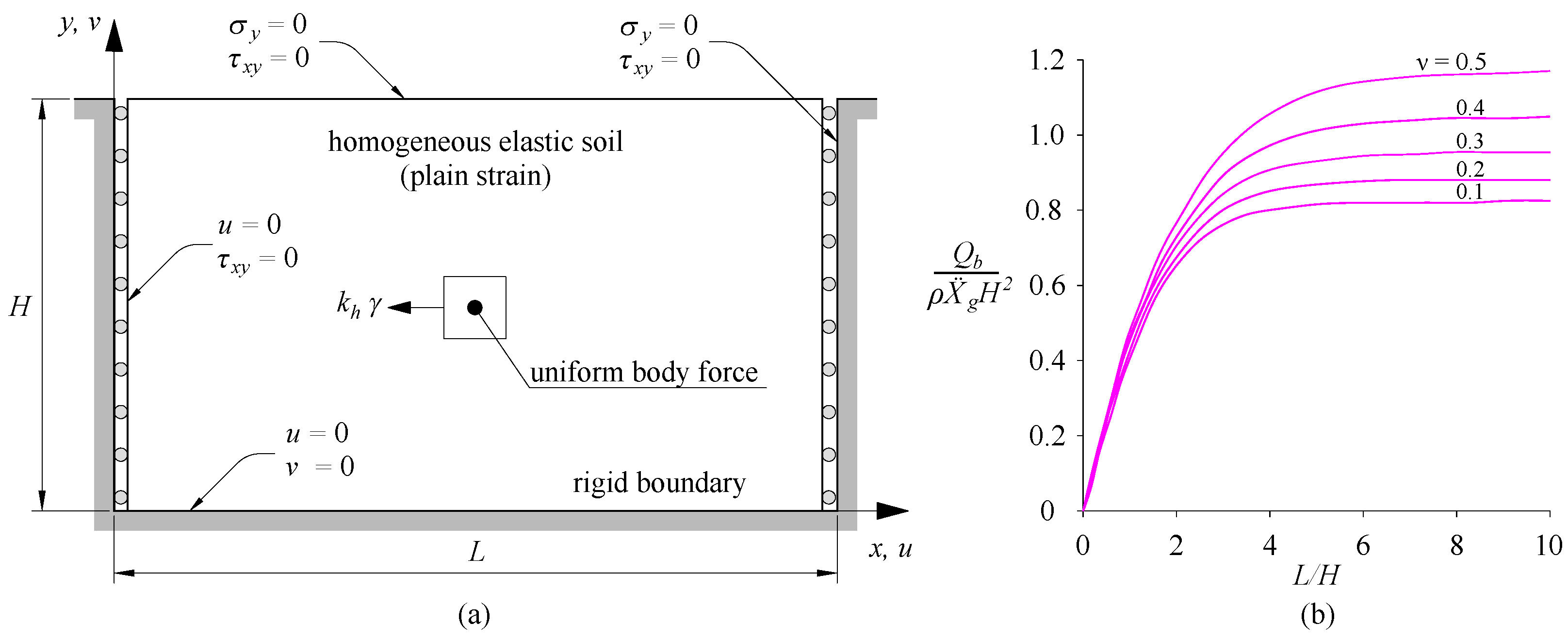
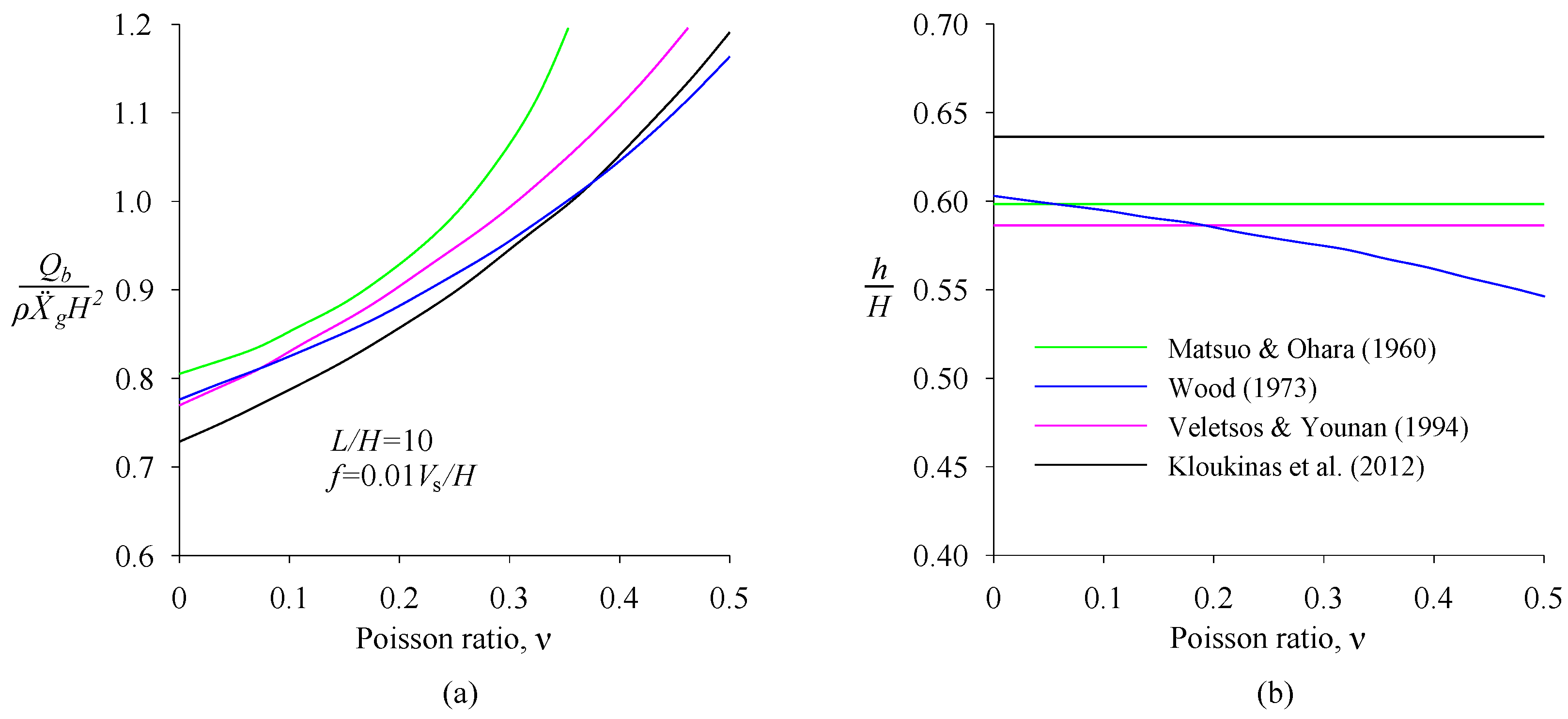
| Wood (1973) [74], | For rigid walls that do not yield, and with finite backfill length subjected to harmonic base motions, a solution was developed. The resultant dynamic pressure acts at 0.55–0.6H above the wall base. |
| Kloukinas et al. (2012) [86], | A more flexible and versatile solution for assessing how rigid walls behave on an elastic stratum. The effect of wall flexibility was not considered. |
| is a compressibility factor | |
| Veletsos and Younan (1994, 1997) [35,77,78], | For massless rigid walls, the harmonic and earthquake response of a semi-infinite uniform layer of viscoelastic material was investigated. The rotation of rigid walls around its base was further considered. The parabolic shear modulus distribution of the backfill was considered. The effect of the wall and base flexibility were also taken into account. |
| Richards et al. (1999) [81], | A straightforward kinematic approach for determining seismic earth pressure. It utilizes the Mohr–Coulomb failure criterion. The shear modulus value is idealized. Interestingly, the actual magnitude of the shear modulus has no impact on the distribution of active earth pressure. |
| Hybrid Methods | |
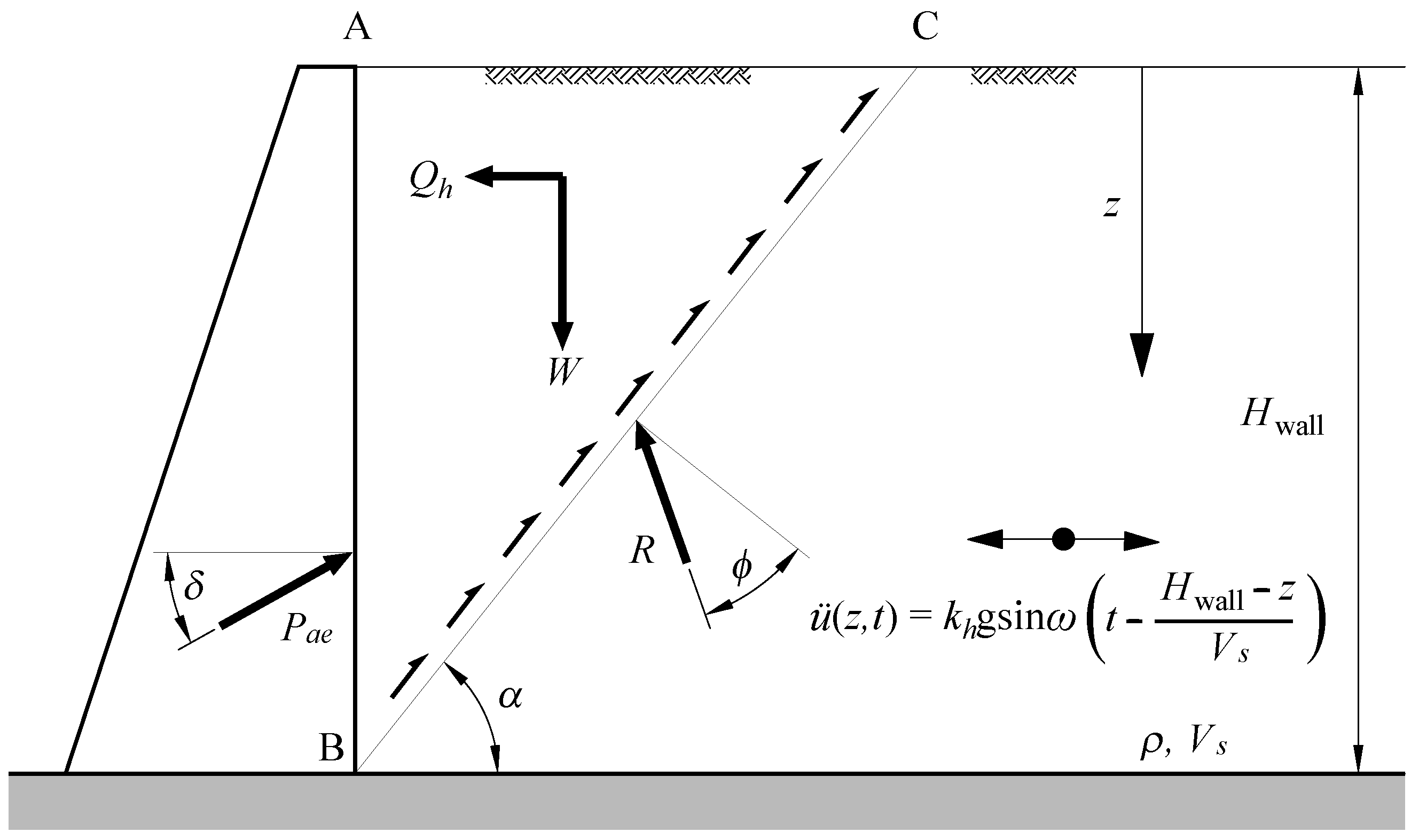
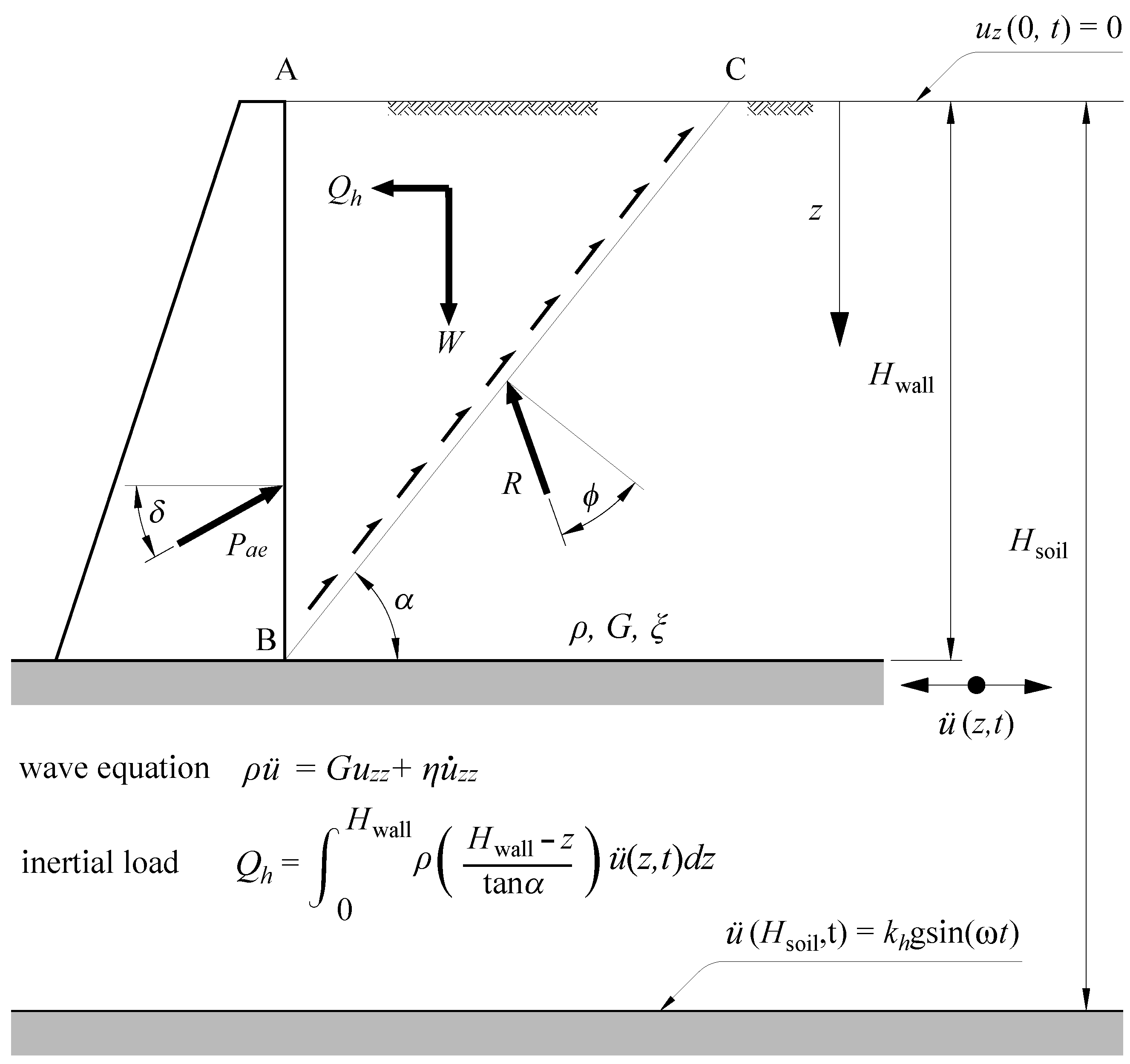
| Steedman and Zeng (1990) [4], | A simple pseudo-dynamic analysis was proposed based on insights from centrifuge tests. The shear wave velocity of the backfill and the input motion frequency are considered. Seismic thrust is higher than above the wall’s base, and it depends on the motion frequency and soil properties. Phase difference of acceleration in the backfill does not influence the seismic thrust. |
| Choudhury and Nimbalkar (2005) [5], | Made modifications to the pseudo-dynamic technique, adapting it to calculate the distribution of dynamic passive pressure behind a vertical wall considering various factors. |
| Choudhury and Nimbalkar (2008) [92], | Rotational displacement of a vertical gravity wall calculated utilizing the Zeng and Steedman [53] method. Wall–soil inertia effect, velocities of the primary and shear waves, and other factors are considered. |
| Rotational acceleration, | |
| Pantelidis (2019) [22], | Based on continuum mechanics approach, Pantelidis [22] obtained earth pressure coefficients for soils and horizontal and vertical pseudostatic conditions. These coefficients were derived for any soil state between the at-rest state and the active or passive state. |
Disclaimer/Publisher’s Note: The statements, opinions and data contained in all publications are solely those of the individual author(s) and contributor(s) and not of MDPI and/or the editor(s). MDPI and/or the editor(s) disclaim responsibility for any injury to people or property resulting from any ideas, methods, instructions or products referred to in the content. |
© 2023 by the authors. Licensee MDPI, Basel, Switzerland. This article is an open access article distributed under the terms and conditions of the Creative Commons Attribution (CC BY) license (https://creativecommons.org/licenses/by/4.0/).
Share and Cite
Khan, S.A.; Karray, M.; Paultre, P. Seismic Behavior of Retaining Walls: A Critical Review of Analytical and Field Performance Studies. Geotechnics 2024, 4, 54-77. https://doi.org/10.3390/geotechnics4010004
Khan SA, Karray M, Paultre P. Seismic Behavior of Retaining Walls: A Critical Review of Analytical and Field Performance Studies. Geotechnics. 2024; 4(1):54-77. https://doi.org/10.3390/geotechnics4010004
Chicago/Turabian StyleKhan, Sabahat Ali, Mourad Karray, and Patrick Paultre. 2024. "Seismic Behavior of Retaining Walls: A Critical Review of Analytical and Field Performance Studies" Geotechnics 4, no. 1: 54-77. https://doi.org/10.3390/geotechnics4010004