
Design of a Biaxial Laminar Shear Box for 1g Shaking Table Tests

 ,
,  , and
, and
Abstract
:1. Introduction
2. Background
3. Performance and Requirements of a Laminar Box
- (a)
- Maintenance of stress similarity in the model as in the prototype—The stress field is not affected by the boundaries at a considerably distance from the end walls. It has to be adequately evaluated by experimental or numerical analysis;
- (b)
- Maintenance of stain similarity between the model and the prototype—The displacement at a particular depth has to be constant. In other words, the horizontal cross section must remain horizontal;
- (c)
- Reduction of the wave reflections on the sidewalls;
- (d)
- Propagation of the shaking to the soil layer. This can be accomplished by the use of a rough base;
- (e)
- Water tightness for saturated soil tests.
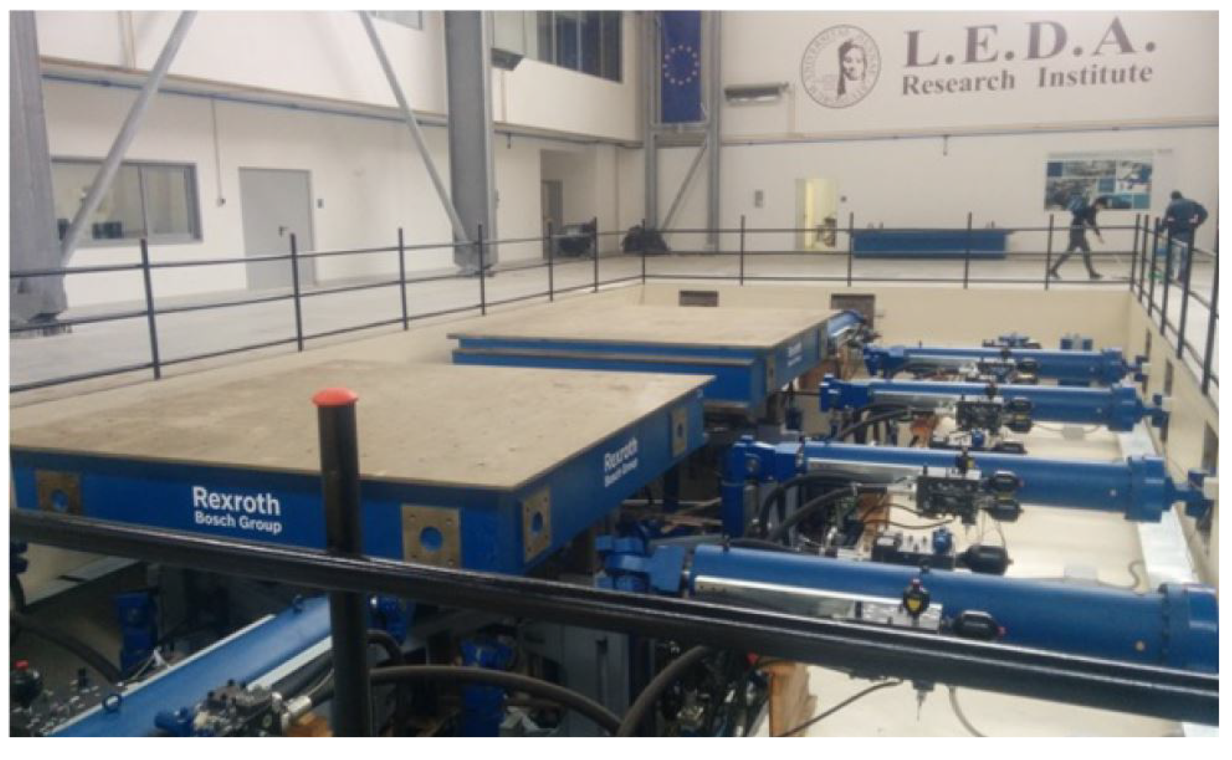
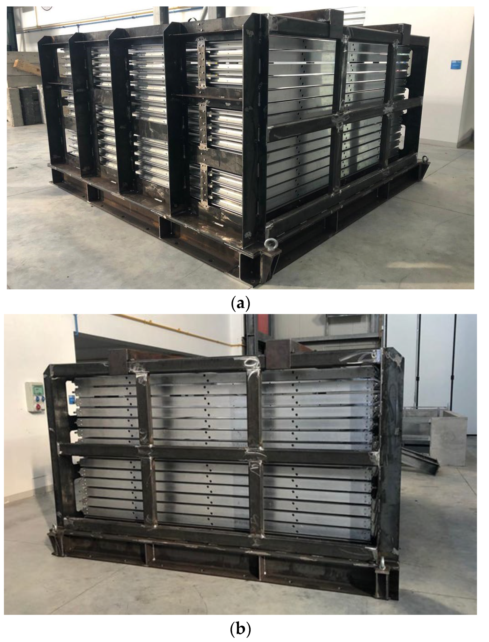
4. New Laminar Shear Box at L.E.D.A.
5. Conclusions
Author Contributions
Funding
Acknowledgments
Conflicts of Interest
References
- Galavi, V.; Petalas, A.; Brinkgreve, R.B.J. Finite element modelling of seismic liquefaction in soils. Geotech. Eng. J. SEAGS AGSSEA 2013, 44, 55–64. [Google Scholar]
- Sadrekarimi, A.; Ghalandarzadeh, A. Evaluation of gravel drains and compacted sand piles in mitigating liquefaction. Proc. Inst. Civ. Eng.-Ground Improv. 2005, 9, 91–104. [Google Scholar] [CrossRef]
- Lentini, V.; Castelli, F. Liquefaction resistance of sandy soils from undrained cyclic triaxial tests. Geotech. Geol. Eng. 2018, 37, 201–216. [Google Scholar] [CrossRef]
- Castelli, F.; Cavallaro, A.; Grasso, S.; Lentini, V. Undrained Cyclic Laboratory Behavior of Sandy Soils. Geosciences 2019, 9, 512. [Google Scholar] [CrossRef] [Green Version]
- Ciancimino, A.; Lanzo, G.; Alleanza, G.A.; Amoroso, S.; Bardotti, R.; Biondi, G.; Cascone, E.; Castelli, F.; Di Giulio, A.; D’onofrio, A.; et al. Dynamic characterization of fine-grained soils in Central Italy by laboratory testing. Bull. Earthq. Eng. 2020, 18, 5503–5531. [Google Scholar] [CrossRef]
- Boulanger, R.W.; Idriss, I.M. CPT and SPT Based Liquefaction Triggering Procedures; Report, No. UCD/CGM-14/01; Center for Geotechnical Modeling, Department of Civil and Environmental Engineering, College of Engineering, University of California: Davis, CA, USA, 2014. [Google Scholar]
- Boulanger, R.W.; Idriss, I.M. CPT-based liquefaction triggering procedure. J. Geotech. Geoenvir. Eng. 2015, 142, 2. [Google Scholar] [CrossRef]
- Castelli, F.; Cavallaro, A.; Grasso, S. SDMT soil testing for the local site response analysis. In Proceedings of the 1st IMEKO TC4 International Workshop on Metrology for Geotechnics, Benevento, Italy, 17–18 March 2016; pp. 143–148, ISBN 978-92-990075-0-1. [Google Scholar]
- Castelli, F.; Lentini, V.; Trifarò, C.A. 1D seismic analysis of earth dams: The example of the Lentini site. Procedia Eng. 2016, 158, 356–361. [Google Scholar] [CrossRef] [Green Version]
- Grasso, S.; Maugeri, M. The Seismic Dilatometer Marchetti Test (SDMT) for Evaluating Liquefaction Potential under Cyclic Loading. In Proceedings of the IV Geotechnical Earthquake Engineering and Soil Dynamic, Sacramento, CA, USA, 18–22 May 2008; ISBN 978-0-7844-0975-6. [Google Scholar] [CrossRef]
- Grasso, S.; Massimino, M.; Sammito, M. New Stress Reduction Factor for Evaluating Soil Liquefaction in the Coastal Area of Catania (Italy). Geosciences 2020, 11, 12. [Google Scholar] [CrossRef]
- Maugeri, M.; Grasso, S. Liquefaction potential evaluation at Catania Harbour (Italy). WIT Trans. Built Environ. 2013, 132, 69–81. [Google Scholar] [CrossRef] [Green Version]
- Bhatnagar, S.; Kumari, S.; Sawant, V.A. Numerical Analysis of Earth Embankment Resting on Liquefiable Soil and Remedial Measures. Int. J. Géoméch. 2016, 16, 04015029. [Google Scholar] [CrossRef]
- Castelli, F.; Grasso, S.; Lentini, V.; Sammito, M. Effects of Soil-Foundation-Interaction on the Seismic Response of a Cooling Tower by 3D-FEM Analysis. Geosciences 2021, 11, 200. [Google Scholar] [CrossRef]
- Makra, A. Evaluation of the UBC3D-PLM Constitutive Model for Prediction of Earthquake Induced Liquefaction on Embankment Dams. Master’s Thesis, Delft University of Technology, Delft, The Netherlands, 2013. [Google Scholar]
- Ishihara, K.; Yamazaki, F. Cyclic Simple Shear Tests on Saturated Sand in Multi-Directional Loading. Soils Found. 1980, 20, 45–59. [Google Scholar] [CrossRef] [Green Version]
- Cavallaro, A.; Capilleri, P.P.; Grasso, S. Site characterization by dynamic in situ and laboratory tests for liquefaction potential evaluation during emilia romagna earthquake. Geosciences 2018, 8, 242. [Google Scholar] [CrossRef] [Green Version]
- Bojadjieva, J.; Sesov, V.; Edip, K.; Gjorgiev, I. Some important aspects in experimental setup for liquefaction studies on shaking table tests. In Proceedings of the 2nd European Conference Earthquake Engineering and Seismology, İstanbul, Turkey, 25–29 August 2014. [Google Scholar]
- Chen, C.H.; Ueng, T.S. Dynamic responses of model pile in saturated sand in shaking table tests. In Proceedings of the 5th International Conference on Earthquake Geotechnical Engineering, Santiago, Chile, 9–14 January 2011. [Google Scholar]
- Mohsan, M.; Kiyota, T.; Munoz, H.; Nihaaj, M.; Katagiri, T. Fabrication and performance of laminar soil box with rigid soil box for liquefaction study. In Bulletin of Earthquake Resistant Structure Research Center 2018; Institute of Industrial Science (IIS), University of Tokyo: Tokyo, Japan, 2018; Volume 51. [Google Scholar]
- Ashford, S.; Rollins, K.; Lane, J. Blast-induced liquefaction for full-scale foundation testing. J. Geotech. Geoen-Vironmental Eng. 2004, 130, 798–806. [Google Scholar] [CrossRef]
- Castelli, F.; Grasso, S.; Lentini, V.; Massimino, M.R. In situ measurements for evaluating liquefaction potential under cyclic loading. In Proceedings of the 1st IMEKO TC-4 Int. Workshop on Metrology for Geotechnics, Benevento, Italy, 17–18 March 2016; pp. 79–84, ISBN 978-92-990075-0-1. [Google Scholar]
- Castelli, F.; Cavallaro, A.; Ferraro, A.; Grasso, S.; Lentini, V.; Massimino, M.R. Static and dynamic properties of soils in catania (Italy). Ann. Geophys. 2018, 61, 221. [Google Scholar] [CrossRef]
- Turan, A.; Hinchberger, S.D.; El Naggar, M.H. Seismic soil–structure interaction in buildings on stiff clay with embedded basement stories. Can. Geotech. J. 2013, 50, 858–873. [Google Scholar] [CrossRef]
- Ecemis, N. Simulation of seismic liquefaction: 1-g model testing system and shaking table tests. Eur. J. Environ. Civ. Eng. 2013, 17, 899–919. [Google Scholar] [CrossRef] [Green Version]
- Prasad, S.K.; Towhata, I.; Chandradhara, G.P.; Nanjunaswamy, P. Shaking table tests in earthquake geotechnical engineering. Curr. Sci. 2004, 87, 1398–1404. [Google Scholar]
- Zayed, M.; Luo, L.; Kim, K.; McCarteney, J.S.; Elgamal, A. Development and performance of a laminar container for seismic centrifuge modeling. In Proceedings of the 3rd International Conference on Performance-Based Design in Earthquake Geotechnical Engineering, Vancouver, BC, Canada, 16–19 July 2017. [Google Scholar]
- Alaie, R.; Chenari, R.J. Design and Performance of a Single Axis Shake Table and a Laminar Soil Container. Civ. Eng. J. 2018, 4, 1326. [Google Scholar] [CrossRef]
- Bhattacharya, S.; Lombardi, D.; Dihoru, L.; Dietz, M.S.; Crewe, A.J.; Taylor, C.A. Model container design for soil-structure interaction studies. In Role of Seismic Testing Facilities in Performance-Based Earthquake Engineering: SERIES Workshop, Geotech, Geological and Earthquake Engineering; Fardis, M.N., Rakicevic, Z.T., Eds.; Springer Science + Business Media: Berlin/Heidelberg, Germany, 2012; Volume 22. [Google Scholar]
- Jafarzadeh, F. Design and evaluation concepts of laminar shear box for 1g shaking table tests. In Proceedings of the 13th World Conference on Earthquake Engineering, Vancouver, BC, Canada, 1–6 August 2004. [Google Scholar]
- Carvalho, A.T.; Bile Serra, J.; Oliveira, F.; Morais, P.; Ribeiro, A.R.; Santos Pereira, C. Design of experimental setup for 1 g seismic load tests on anchored retaining walls. In Physical Modelling in Geotechnics; Springman, S., Laue, J., Seward, L., Eds.; Taylor and Francis Group: London, UK, 2010. [Google Scholar]
- Gibson, A. Physical Scale Modeling of Geotechnical Structures at One-G. Ph.D. Thesis, California Institute of Technology, Pasadena, CA, USA, 1996. [Google Scholar]
- Pamuk, A.; Gallagher, P.M.; Zimmie, T.F. Remediation of piled foundations against lateral spreading by passive site stabilization technique. Soil Dyn. Earthq. Eng. 2007, 27, 864–874. [Google Scholar] [CrossRef]
- Sarlak, A.; Saeedmonir, H.; Gheyretmand, C. Numerical and experimental study of soil-structure interaction in structures resting on loose soil using laminar shear box. Int. J. Eng. 2017, 30, 1654–1663. [Google Scholar]
- Takahashi, A.; Takemura, J.; Suzuki, A.; Kusakabe, O. Development and performance of an active type shear box in a cen-trifuge. Int. J. Phys. Model. Geotech. 2001, 1, 1–17. [Google Scholar]
- Zeghal, M.; El Shafee, O.; Abdoun, T. Analysis of soil liquefaction using centrifuge tests of a site subjected to biaxial shaking. Soil Dynam. Earthq. Eng. 2018, 114, 229–241. [Google Scholar] [CrossRef]
- Ng, C.W.; Li, X.; Van Laak, P.A.; Hou, D.Y. Centrifuge modeling of loose fill embankment subjected to uni-axial and bi-axial earthquakes. Soil Dyn. Earthq. Eng. 2004, 24, 305–318. [Google Scholar] [CrossRef]
- Suits, L.D.; Sheahan, T.; Ueng, T.-S.; Wang, M.-H.; Chen, M.-H.; Chen, C.-H.; Peng, L.-H. A Large Biaxial Shear Box for Shaking Table Test on Saturated Sand. Geotech. Test. J. 2006, 29. [Google Scholar] [CrossRef]
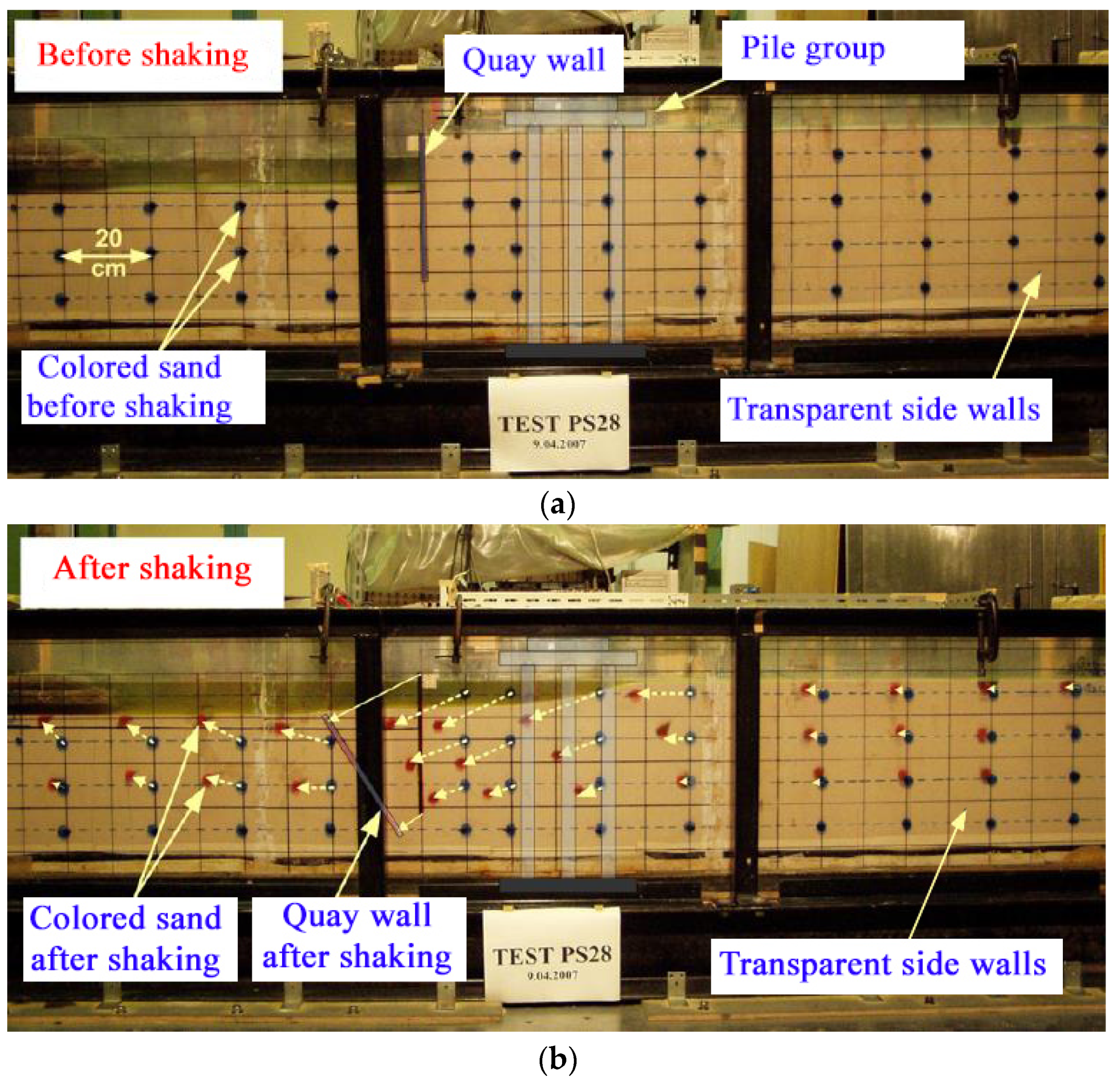
- Motamed, R.; Towhata, I. Mitigation measures for pile groups behind quay walls subjected to lateral flow of liquefied soil: Shake table model tests. Soil Dyn. Earthq. Eng. 2010, 30, 1043–1060. [Google Scholar] [CrossRef]
- Özener, P.T.; Özaydin, K.; Berilgen, M. Numerical and physical modeling of liquefaction mechanisms in layered sands. In Proceedings of the Geotechnical Earthquake Engineering and Soil Dynamics IV, Sacramento, CA, USA, 18–22 May 2008. [Google Scholar]
- Madabhushi, S.; Schofield, A.; Zeng, X. Complementary Shear Stresses in Dynamic Centrifuge Modelling. ASTM Spec. Tech. Publ. 2009, 1213, 346. [Google Scholar] [CrossRef] [Green Version]
- Saha, R.; Haldar, S.; Dutta, S.C. Influence of dynamic soil-pile raft-structure interaction: An experimental approach. Earthq. Eng. Eng. Vib. 2015, 14, 625–645. [Google Scholar] [CrossRef]
- Fishman, K.L.; Mander, J.B.; Richards, R., Jr. Laboratory study of seismic free-field response of sand. Soil Dyn. Earthq. Eng. 1995, 14, 33–43. [Google Scholar] [CrossRef]
- Zeng, X.; Schofield, A.N. Design and performance of an equivalent-shear-beam container for earthquake centrifuge testing. Geotechnique 1996, 46, 83–102. [Google Scholar] [CrossRef]
- Hushmand, B.; Scott, R.F.; Crouse, C.B. Centrifuge liquefaction tests in a laminar box. Geotechnique 1988, 38, 253–262. [Google Scholar] [CrossRef] [Green Version]
- Dar, A.R. Development of Flexible Shear-Stack for Shaking Table of Geotechnical Problems. Ph.D. thesis, University of Bristol, Bristol, UK, 1993. [Google Scholar]
- Madabhushi, S.P.G.; Butler, G.; Schofield, A.N. Design of an Equivalent Shear Beam (ESB) container for use on the US Army. In Proceedings of the International Conference Centrifuge 98, Tokyo, Japan, 23–25 September 1998. [Google Scholar]
- Teymur, B.; Madabhushi, S.P.G. Experimental study of boundary effects in dynamic centrifuge modelling. Géotechnique 2003, 53, 463–655. [Google Scholar] [CrossRef]
- Massimino, M.R.; Abate, G.; Grasso, S. Some aspects of DSSI in the dynamic response of fully-coupled soil-structure systems. Riv. Ital. Geotec. 2019, 1, 44–70. [Google Scholar] [CrossRef]
- Biondi, G.; Massimino, M.R.; Maugeri, M. Experimental study in the shaking table of the input motion characteristics in the dynamic SSI of a SDOF model. Bull. Earthq. Eng. 2014, 13, 1835–1869. [Google Scholar] [CrossRef]
- Crewe, A.W.; Lings, M.L.; Taylor, C.A.; Yeung, A.K.; Andrighetto, R. Development of a large shear-stack for resting dry sand and simple direct foundations on a shaking table. In Proceedings of the 5th SECED Conference on European Seismic Design Practice, Chester, UK, 26–27 October 1995. [Google Scholar]
- Aldaikh, H.; Alexander, N.; Ibraim, E.; Knappett, J. Shake table testing of the dynamic interaction between two and three adjacent buildings (SSSI). Soil Dyn. Earthq. Eng. 2016, 89, 219–232. [Google Scholar] [CrossRef] [Green Version]
- Penna, A.; Sorrentino, G.; d’Onofrio, A.; Silvestri, F.; Simonelli, A.L. Dynamic behaviour of the Leighton Buzzard Sand-B under very low confining stresses. In Proceedings of the 1st IMEKO TC4 International Workshop on Metrology for Geotechnics (MetroGeotechnics 2016), Benevento, Italy, , 17–18 March 2016; pp. 79–84, ISBN 978-92-990075-0-1. [Google Scholar]
- Chidichimo, A.; Cairo, R.; Dente, G.; Taylor, C.A.; Mylonakis, G. 1-g Experimental investigation of bi-layer soil response and kinematic pile bending. Soil Dyn. Earthq. Eng. 2014, 67, 219–232. [Google Scholar] [CrossRef] [Green Version]
- Durante, M.G.; Karamitros, D.; Di Sarno, L.; Sica, S.; Taylor, C.A.; Mylonakis, G.; Simonelli, A.L. Characterisation of shear wave velocity profiles of non-uniform bi-layer soil deposits: Analytical evaluation and experimental validation. Soil Dyn. Earthq. Eng. 2015, 75, 44–54. [Google Scholar] [CrossRef] [Green Version]
- Fiorentino, G.; Cengiz, C.; De Luca, F.; Mylonakis, G.; Kramitros, D.; Dietz, M.; Dihoru, L.; Lavorato, D.; Briseghella, B.; Isa-kovic, T.; et al. Integral abutment bridges: Investigation of seismic soil-structure in-teraction effects by shaking table testing. Earthq. Eng. Struct. Dyn. 2021, 50, 1517–1538. [Google Scholar] [CrossRef]
- Suits, L.D.; Sheahan, T.C.; Thevanayagam, S.; Kanagalingam, T.; Reinhorn, A.; Tharmendhira, R.; Dobry, R.; Pitman, M.; Abdoun, T.; Elgamal, A.; et al. Laminar Box System for 1-g Physical Modeling of Liquefaction and Lateral Spreading. Geotech. Test. J. 2009, 32, 438–449. [Google Scholar] [CrossRef] [Green Version]
- Ueng, T.; Wu, C.; Cheng, H.; Chen, C. Settlements of saturated clean sand deposits in shaking table tests. Soil Dyn. Earthq. Eng. 2010, 30, 50–60. [Google Scholar] [CrossRef]
- Yao, S.; Kobayaski, K.; Yoshida, N.; Hiroshi, M. Interactive behaviour of soil-pile-superstructure system in transient state to liquefaction by means of large shake table tests. Soil Dyn. Earthq. Eng. 2004, 24, 397–409. [Google Scholar] [CrossRef]
- Ueng, T.S.; Chen, C.H.; Tsou, C.F. Preparation of a large mailiao silty sand specimen for shaking table test. In Proceedings of the 4th International Conference on Earthquake Geotechnical Engineering, Thessaloniki, Greece, 25–28 June 2007. [Google Scholar]
- Fiegel, G.L.; Hudson, M.; Idriss, I.M.; Kutter, B.L.; Zeng, X. Effect of model container on dynamic soil response. In Proceedings of the International Conference Centrifuge 94, Singapore, 31 August–2 September 1994; Leung, C.F., Lee, F.-H., Tan, T.S., Eds.; Balkema: Singapore, 1994; pp. 145–150. [Google Scholar]
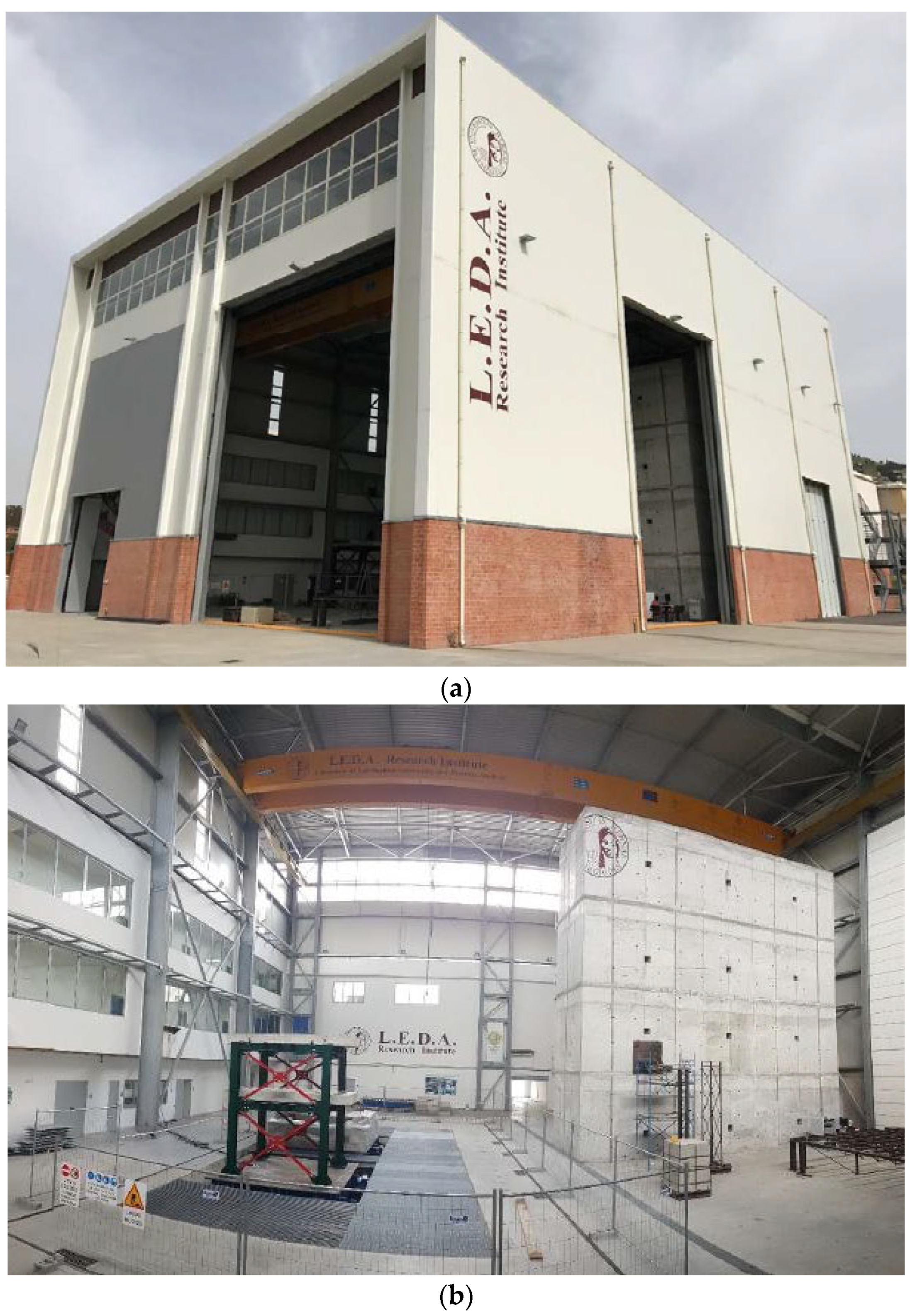
- Navarra, G.; Lo Iacono, F.; Oliva, M.; Tesoriere, G. A new research facility: The Laboratory of Earthquake engineering and Dynamic Analysis (L.E.D.A.). In Proceedings of the XXII Congresso-Associazione Italiana di Meccanica Teorica e Applicata-AIMETA 2015, Genoa, Italy, 14–17 September 2015; pp. 297–306, ISBN 978-88-97752-55-4. [Google Scholar]
- Bandini, V.; Cascone, E.; Biondi, G.; Di Filippo, G.; Ingegneri, S.; Casablanca, O.; Aliberti, D.; Genovese, F. The shaking table with laminar box of the University of Messina. In Earthquake Geotechnical Engineering for Protection and Development of Environment and Constructions; Silvestri, F., Moraci, N., Eds.; CRC Press: Boca Raton, FL, USA, 2019; ISBN 978-0-367-14328-2. [Google Scholar]
- Castelli, F.; Lentini, V.; Grasso, S. Recent developments for the seismic risk assessment. Bull. Earthq. Eng. 2017, 15, 5093–5117. [Google Scholar] [CrossRef]


| Reference | 1g/n-g | Direction | Design |
|---|---|---|---|
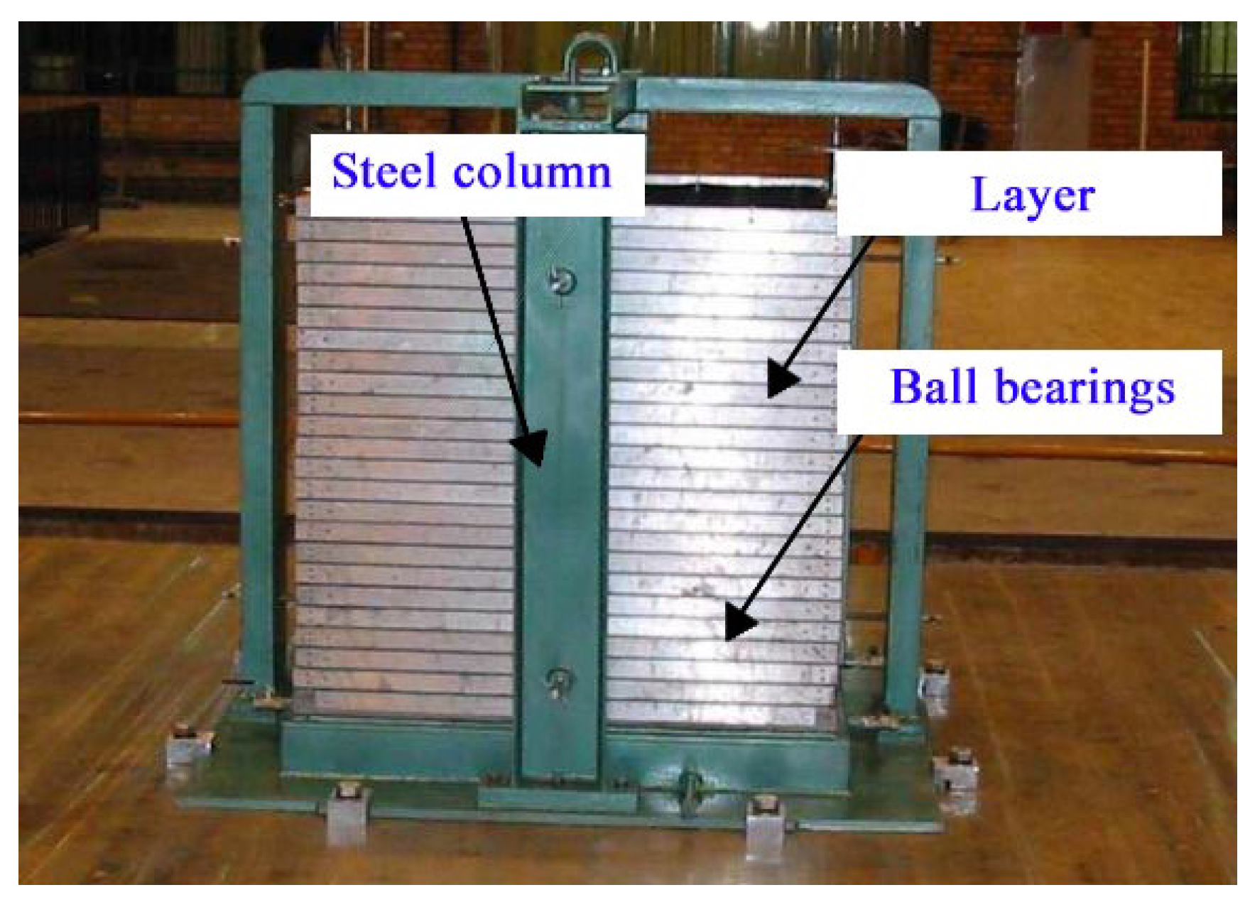
| Alaie & Chenari [28] | 1g | 1D | Layers supported by ball bearings |
| Ecemis [25] | 1g | 1D | Layers supported by rollers |
| Zayed et al. [27] | n-g | 1D | Layers supported by bearings connected to an external frame |
| Mohsan et al. [20] | n-g | 1D | Layers placed in a skeleton supported by linear bearing |
| Thevanayagam et al. [57] | n-g | 2D | Layers supported by ball bearings |
| Zeghal et al. [36] | n-g | 2D | Layers supported by roller bearings |
| Jafarzadeh [30] | 1g | 2D | Layers supported by ball bearings |
| Ueng et al. [38] | 1g | 2D | Layers of frames supported on the surrounding rigid steel walls |
| Feature | Single Table |
|---|---|
| Dimensions [m] | 4.0 × 4.0 |
| DOF | 6 |
| Payload [t] | 60 |
| Max Frequency [Hz] | 60 |
| Stroke (horizontal axes) [mm] | ±400 |
| Stroke (vertical axis) [mm] | ±250 |
| Velocity (horizontal axes) [mm/s] | ±2200 |
| Velocity (vertical axis) [mm/s] | ±1500 |
| Acceleration (horizontal axes) [g] | ±1.50 |
| Acceleration (vert. axis) [g] | ±1.00 |
| Component | Property | Value |
|---|---|---|
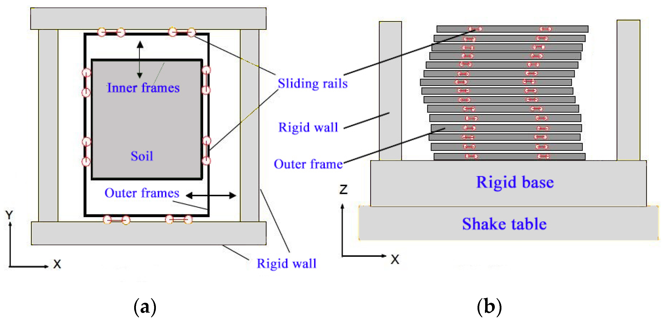
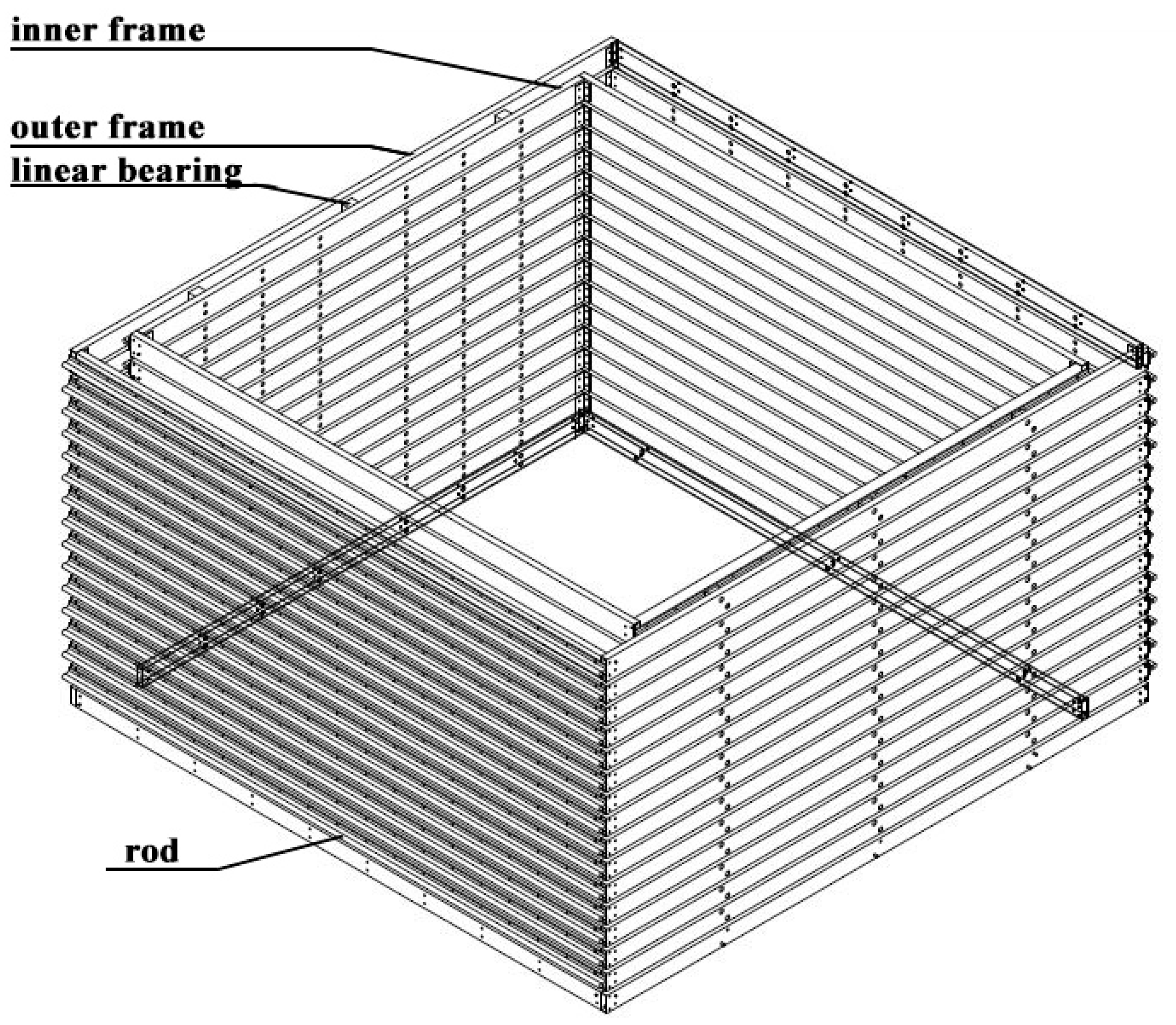
| Inner frame | Mass | 12.07 kg |
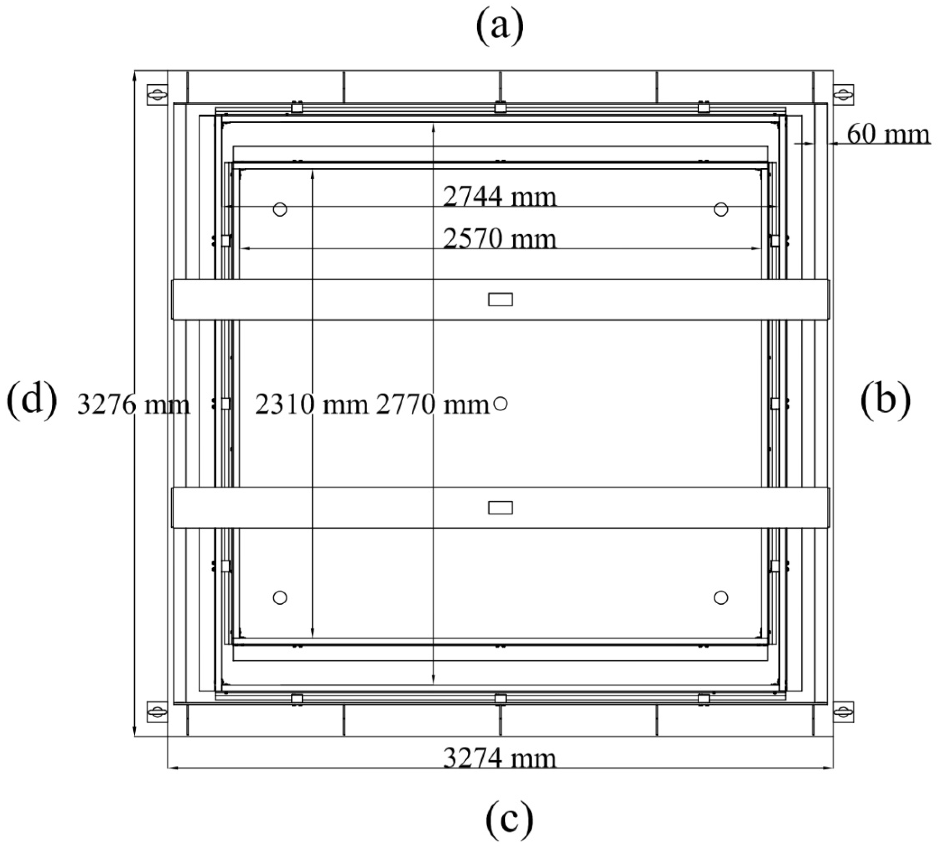
| Internal Dimensions | (2570 × 2310) mm2 | |
| Number | 16 | |
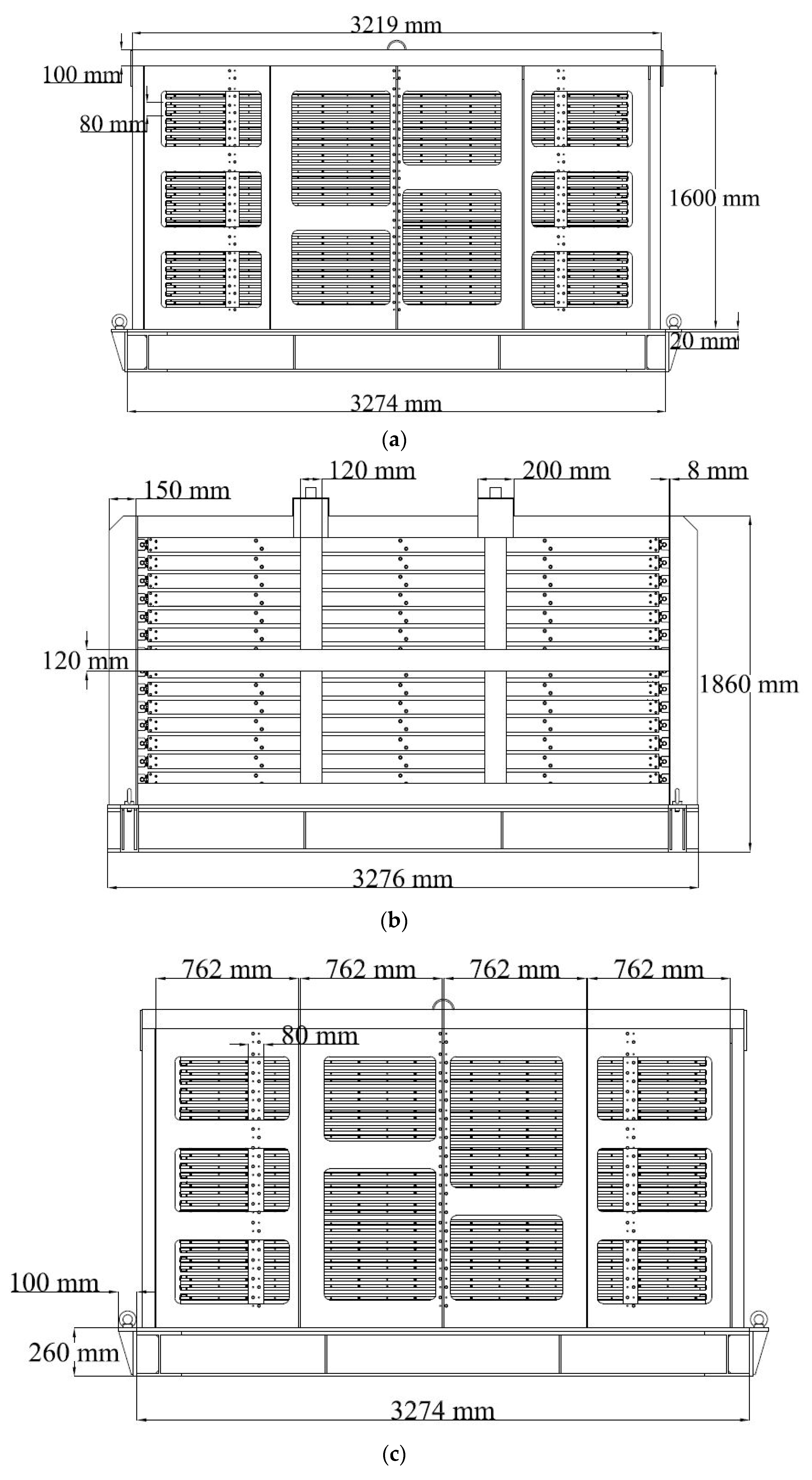
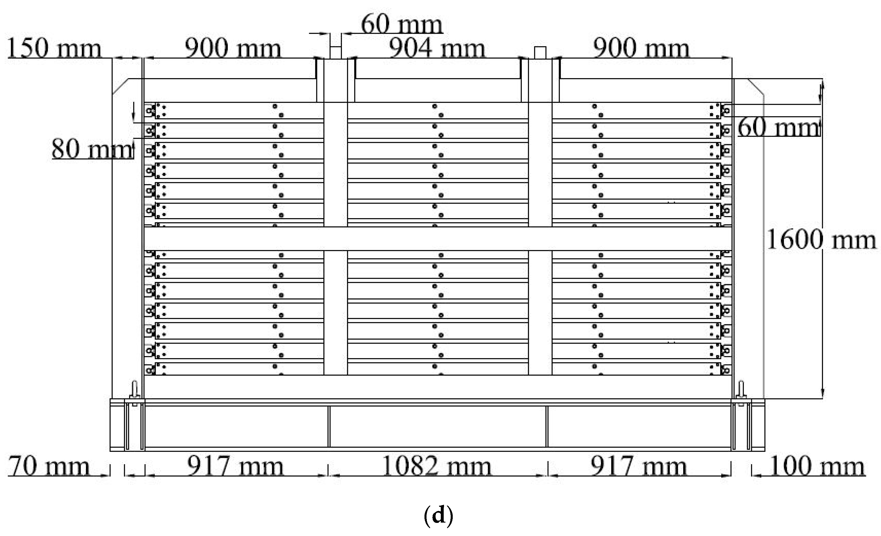
| Height | 80 mm | |
| Outer frame | Mass | 12.53 kg |
| Internal Dimensions | (2744 × 2770) mm2 | |
| Number | 16 | |
| Height | 80 mm | |
| Rod (inner frame) | Length | 2370 mm |
| Diameter | 19 mm | |
| Number | 30 | |
| Rod (outer frame) | Length | 2804 mm |
| Diameter | 19 mm | |
| Number | 30 | |
| Linear bearing | Number | 180 |
| Gap between frames | Dimension | 20 mm |
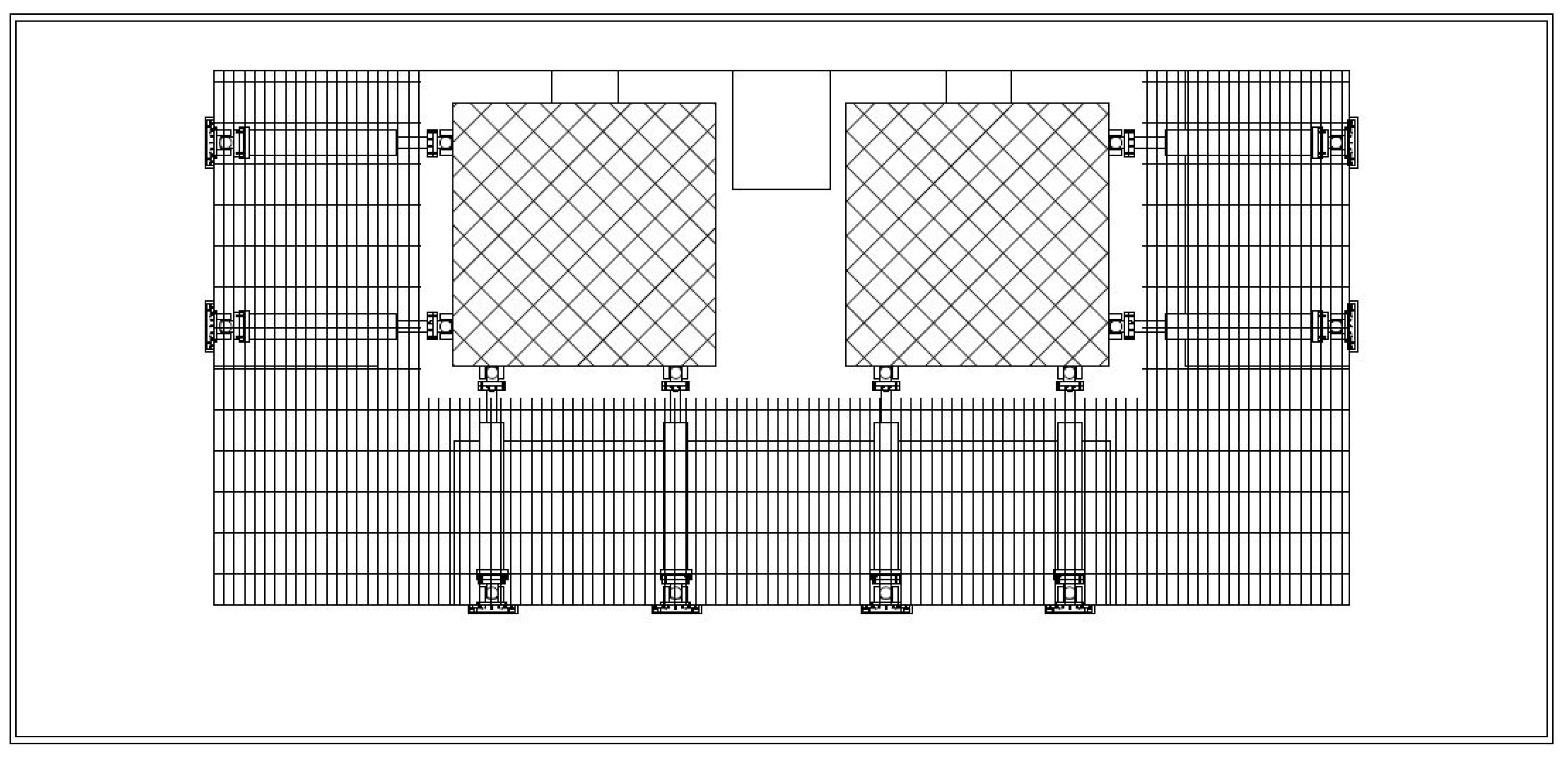
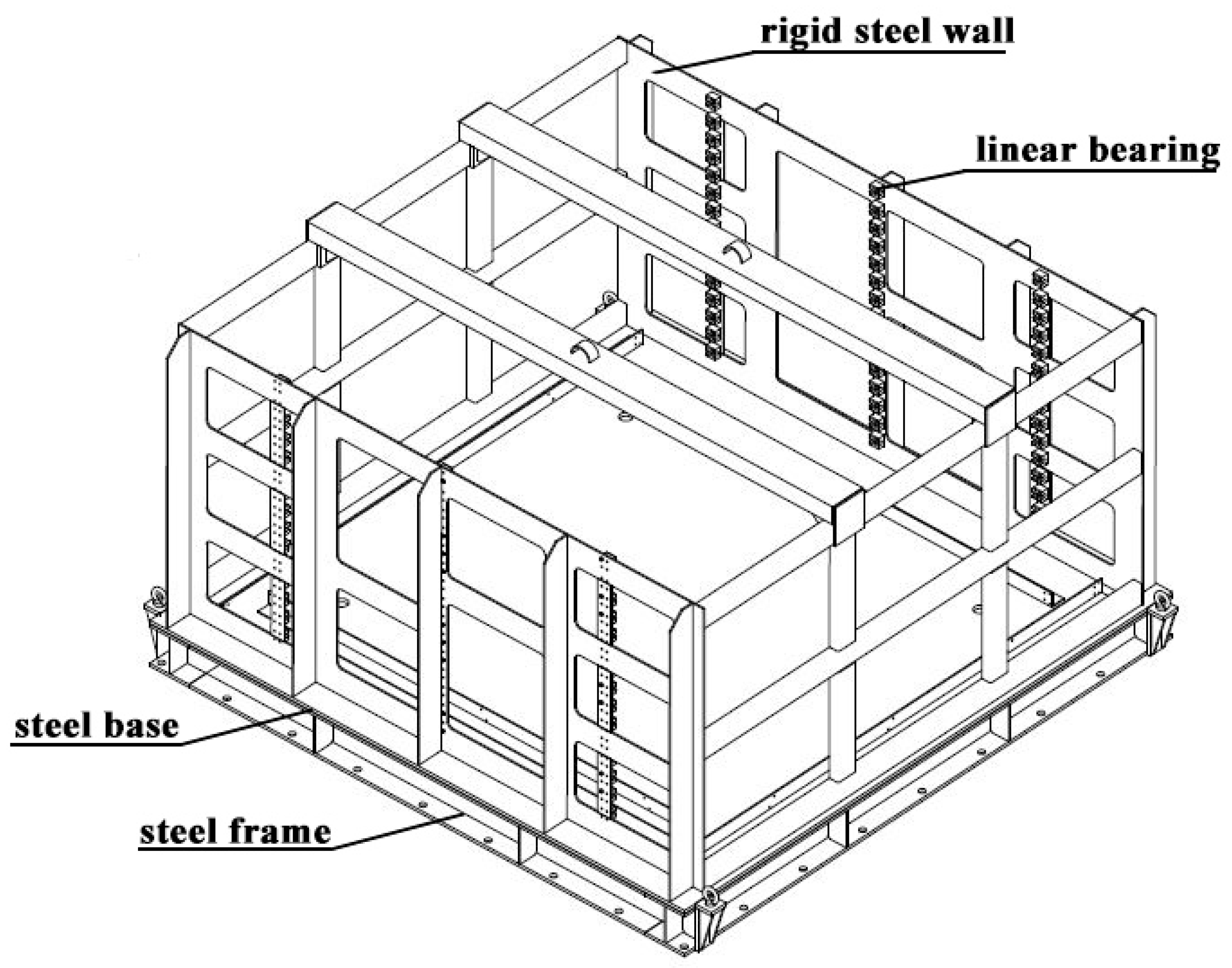
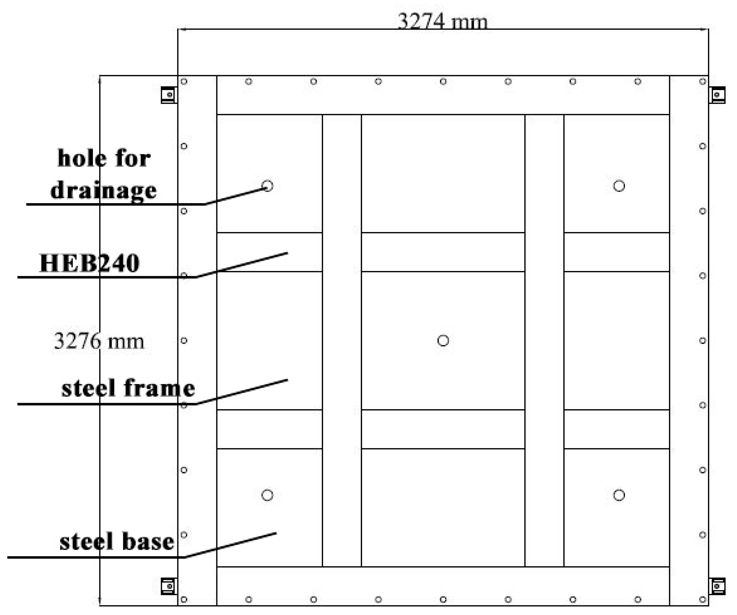
| Steel base | Mass | 1682.89 kg |
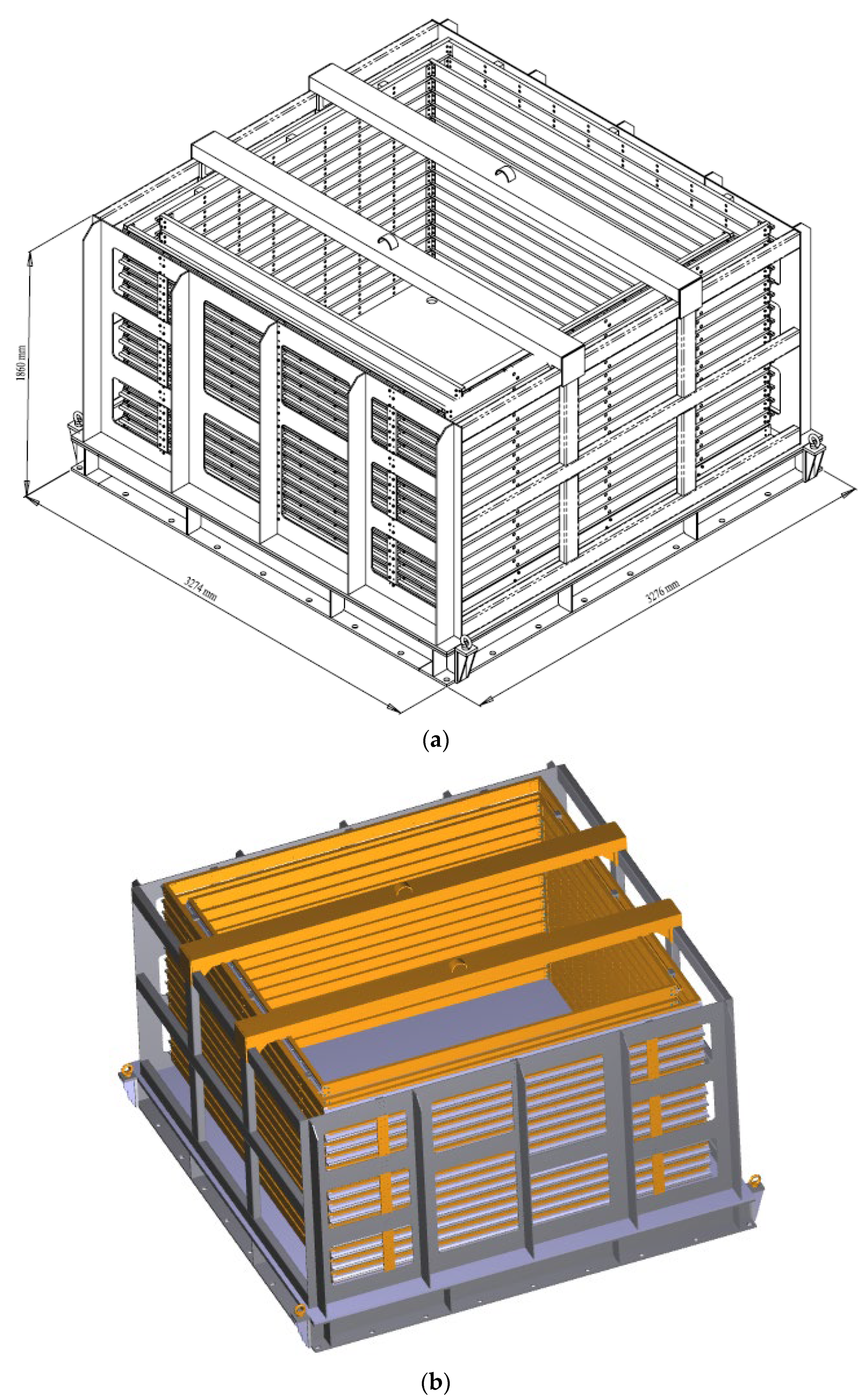
| Dimensions | (3274 × 3276) mm2 | |
| Height | 20 mm | |
| Steel walls | Total mass | 592.94 kg |
| Steel frame | Total mass | 1359.83 kg |
| Total mass of the laminar box | 4033.27 kg |
Publisher’s Note: MDPI stays neutral with regard to jurisdictional claims in published maps and institutional affiliations. |
© 2022 by the authors. Licensee MDPI, Basel, Switzerland. This article is an open access article distributed under the terms and conditions of the Creative Commons Attribution (CC BY) license (https://creativecommons.org/licenses/by/4.0/).
Share and Cite
Castelli, F.; Grasso, S.; Lentini, V.; Sammito, M.S.V. Design of a Biaxial Laminar Shear Box for 1g Shaking Table Tests. Geotechnics 2022, 2, 467-487. https://doi.org/10.3390/geotechnics2020023
Castelli F, Grasso S, Lentini V, Sammito MSV. Design of a Biaxial Laminar Shear Box for 1g Shaking Table Tests. Geotechnics. 2022; 2(2):467-487. https://doi.org/10.3390/geotechnics2020023
Chicago/Turabian StyleCastelli, Francesco, Salvatore Grasso, Valentina Lentini, and Maria Stella Vanessa Sammito. 2022. "Design of a Biaxial Laminar Shear Box for 1g Shaking Table Tests" Geotechnics 2, no. 2: 467-487. https://doi.org/10.3390/geotechnics2020023