
Optimization of a Cost-Constrained, Hydraulic Knee Prosthesis Using a Kinematic Analysis Model

 ,
,
Abstract
:1. Introduction
2. Materials and Methods

| Criteria | Specification |
|---|---|
| Stability | Provide mechanism to arrest flexion. |
| Weight limit | Support patient of 100 kg. |
| Maintenance ease | Use retail parts commonly available. |
| Cost | Cost less than USD 500. |
| Variable cadence | Include mechanism for variable swing control. |
| Supportive yield for sitting down | Include mechanism for variable knee resistance. |
| Knee locking | Must have immediate effect from stability mechanism. |
| Redesign amount | Minimally redesign IM knee. |
| Degree of flexion | Minimum 120 degrees of flexion. |
| Weight | Weigh less than 2.27 kg (5 lb) [18]. |
2.1. Mathematical Model
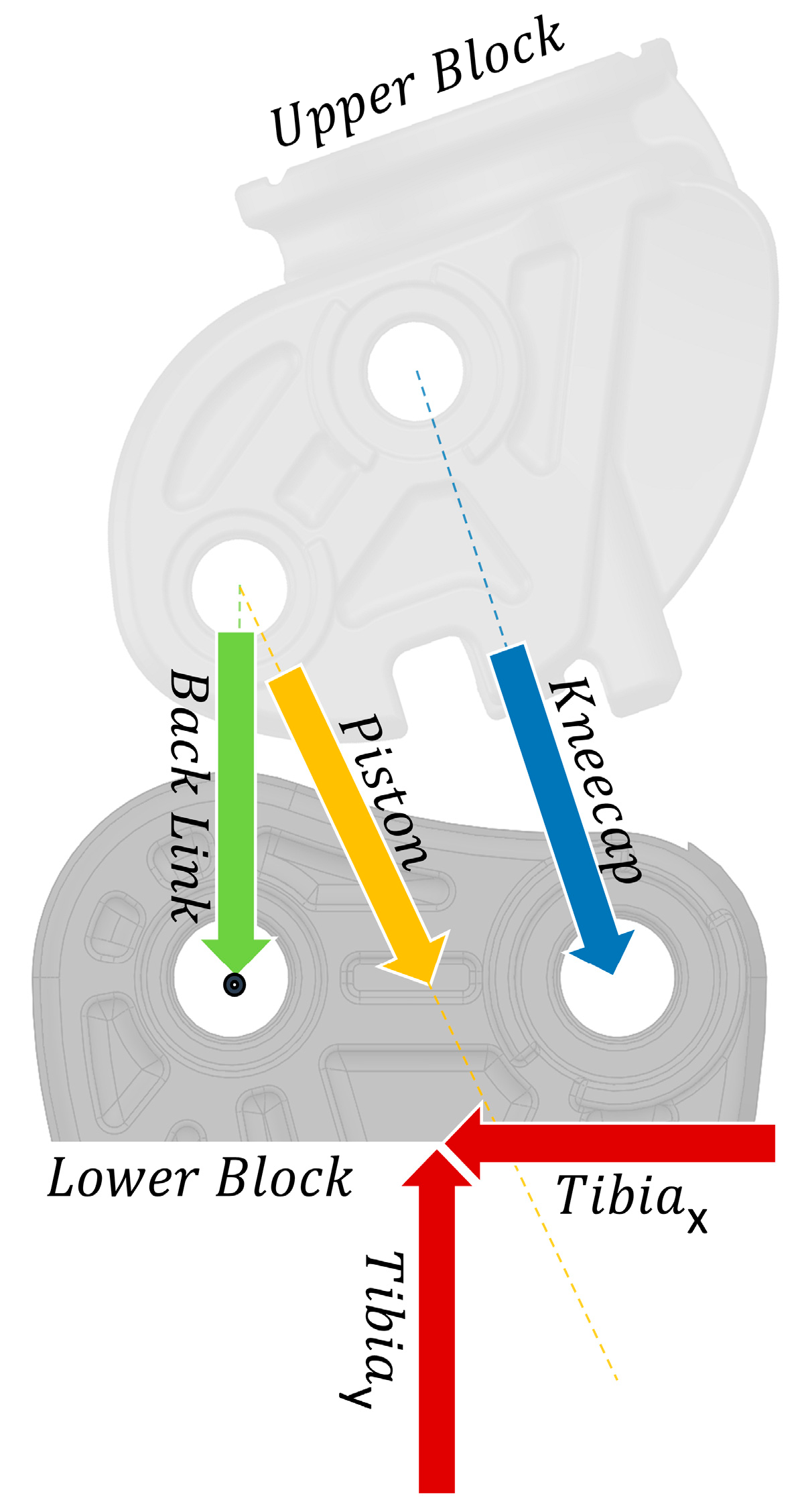
2.1.1. Initial Position Problem
2.1.2. Kinematic Analysis
2.1.3. Free Body Diagram
2.1.4. Force Calculations
2.1.5. Validation
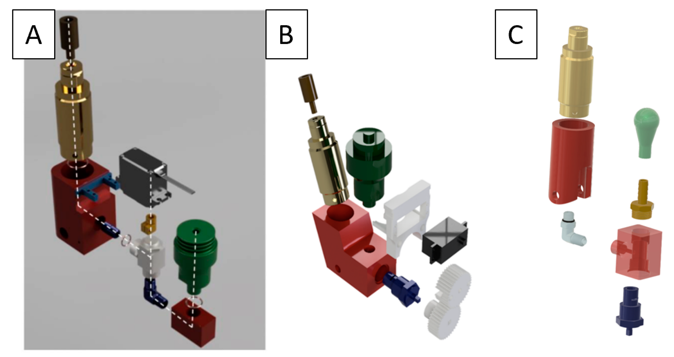
2.2. Components
2.2.1. Selection Criteria
2.2.2. Piston
Selection
Validation
2.2.3. Valve
Selection
Validation
2.2.4. Reservoir
Selection
Validation
2.2.5. Manifold
Selection
Validation
2.2.6. Frame
Selection
Validation
2.2.7. Assembly Validation
System Angular Velocity
System Mechanical Load
3. Results
3.1. Mathematical Model
3.2. Valve Torque
3.3. Hydraulic System
3.4. Angular Velocity
3.5. Frame
3.6. Cost and Weight
4. Discussion
4.1. Future Work
4.2. Limitations
5. Conclusions
Author Contributions
Funding
Institutional Review Board Statement
Informed Consent Statement
Data Availability Statement
Conflicts of Interest
References
- WHO. World Report on Disability; WHO: Geneva, Switzerland, 2011. [Google Scholar]
- Amputee Coalition. Amputee Statistics You Ought to Know. 2012. Available online: http://www.advancedamputees.com/amputee-statistics-you-ought-know (accessed on 3 February 2020).
- Ziegler-Graham, K.; MacKenzie, E.J.; Ephraim, P.L.; Travison, T.G.; Brookmeyer, R. Estimating the prevalence of limb loss in the United States: 2005 to 2050. Arch. Phys. Med. Rehabil. 2008, 89, 422–429. [Google Scholar] [CrossRef] [PubMed]
- Michael, J. Article on Amputee Demographics. 2001. Available online: http://www.oandp.com/news/jmcorner/2001-02/2.asp (accessed on 2 June 2017).
- Johansson, J.L.; Sherrill, D.M.; Riley, P.O.; Bonato, P.; Herr, H. A clinical comparison of variable-damping and mechanically passive prosthetic knee devices. Am. J. Phys. Med. Rehabil. Assoc. Acad. Physiatr. 2005, 84, 563–575. [Google Scholar] [CrossRef]
- Hafner, B.J.; Willingham, L.L.; Buell, N.C.; Allyn, K.J.; Smith, D.G. Evaluation of Function, Performance, and Preference as Transfemoral Amputees Transition From Mechanical to Microprocessor Control of the Prosthetic Knee. Arch. Phys. Med. Rehabil. 2007, 88, 207–217. [Google Scholar] [CrossRef] [PubMed]
- Martinez-Villalpando, E.C.; Herr, H. Agonist-antagonist active knee prosthesis: A preliminary study in level-ground walking. J. Rehabil. Res. Dev. 2009, 46, 361–374. [Google Scholar] [CrossRef] [PubMed]
- Prinsen, E.C.; Nederhand, M.; Sveinsdóttir, H.; Prins, M.; van der Meer, F.; Koopman, H.; Rietman, J. The influence of a user-adaptive prosthetic knee across varying walking speeds: A randomized cross-over trial. Gait Posture 2017, 51, 254–260. [Google Scholar] [CrossRef] [PubMed]
- Hafner, B.J.; Smith, D.G. Differences in function and safety between Medicare Functional Classification Level-2 and -3 transfemoral amputees and influence of prosthetic knee joint control. J. Rehabil. Res. Dev. 2009, 46, 417–433. [Google Scholar] [CrossRef]
- Chen, S.; Ravallion, M. The Developing World is Poorer than We Thought, but No Less Successful in the Fight against Poverty. Q. J. Econ. 2010, 125, 1577–1625. [Google Scholar] [CrossRef]
- Galey, L.J. Development and Initial Testing of a Low-Cost, Electronic, Microprocessor-Controlled Prosthetic Knee. 2016. Available online: http://digitalcommons.utep.edu/dissertations/AAI10251518 (accessed on 9 May 2017).
- Galey, L.J.; Gonzalez, R.V. Design and Initial Evaluation of a Low-Cost Microprocessor-Controlled Above-Knee Prosthesis: A Case Report of 2 Patients. Prosthesis 2022, 4, 60–72. [Google Scholar] [CrossRef]
- Gard, S.A.; Childress, D.S.; Uellendahl, J.E. The Influence of Four-Bar Linkage Knees on Prosthetic Swing-Phase Floor Clearance. J. Prosthet. Orthot. 1996, 8, 34–40. [Google Scholar] [CrossRef]
- Gailey, R.; Allen, K.; Castles, J.; Kucharik, J.; Roeder, M. Review of secondary physical conditions associated with lower-limb amputation and long-term prosthesis use. J. Rehabil. Res. Dev. 2008, 45, 15–29. [Google Scholar] [CrossRef] [PubMed]
- Tang, P.C.Y.; Ravji, K.; Key, J.J.; Mahler, D.B.; Blume, P.A.; Sumpio, B. Let Them Walk! Current Prosthesis Options for Leg and Foot Amputees. J. Am. Coll. Surg. 2008, 206, 548–560. [Google Scholar] [CrossRef] [PubMed]
- ISO 10328:2006; Prosthetics-Structural Testing of Lower-Limb Prostheses—Requirements and Test Methods. International Organization for Standardization: Geneva, Switzerland, 2006.
- Keller, T.S.; Weisberger, A.M.; Ray, J.L.; Hasan, S.S.; Shiavi, R.G.; Spengler, D.M. Relationship between vertical ground reaction force and speed during walking, slow jogging, and running. Clin. Biomech. 1996, 11, 253–259. [Google Scholar] [CrossRef] [PubMed]
- Sup, F.; Bohara, A.; Goldfarb, M. Design and Control of a Powered Transfemoral Prosthesis. Int. J. Rob. Res. 2008, 27, 263–273. [Google Scholar] [CrossRef] [PubMed]
- Winter, D.A. Biomechanics and Motor Control of Human Movement, 2nd ed.; John Wiley & Sons: Hoboken, NJ, USA, 1990. [Google Scholar]
- Selles, R.W.; Bussmann, J.B.J.; Wagenaar, R.C.; Stam, H.J. Effects of prosthetic mass and mass distribution on kinematics and energetics of prosthetic gait: A systematic review. Arch. Phys. Med. Rehabil. 1999, 80, 1593–1599. [Google Scholar] [CrossRef] [PubMed]
- Godest, A.C.; Beaugonin, M.; Haug, E.; Taylor, M.; Gregson, P.J. Simulation of a knee joint replacement during a gait cycle using explicit finite element analysis. J. Biomech. 2002, 35, 267–275. [Google Scholar] [CrossRef] [PubMed]
- Narang, Y.S.; Arelekatti, V.N.M.; Winter, A.G. The Effects of Prosthesis Inertial Properties on Prosthetic Knee Moment and Hip Energetics Required to Achieve Able-Bodied Kinematics. IEEE Trans. Neural Syst. Rehabil. Eng. 2016, 24, 754–763. [Google Scholar] [CrossRef]
- Barr, A.E.; Lohmann Siegel, K.; Danoff, J.V.; McGarvey, C.L., III; Tomasko, A.; Sable, I.; Stanhope, S.J. Biomechanical comparison of the energy-storing capabilities of SACH and Carbon Copy II prosthetic feet during the stance phase of gait in a person with below-knee amputation. Phys. Ther. 1992, 72, 344–354. [Google Scholar] [CrossRef] [PubMed]
- Nolan, L.; Wit, A.; Dudziñski, K.; Lees, A.; Lake, M.; Wychowañski, M. Adjustments in gait symmetry with walking speed in trans-femoral and trans-tibial amputees. Gait Posture 2003, 17, 142–151. [Google Scholar] [CrossRef] [PubMed]
- Segal, A.D.; Orendurff, M.S.; Klute, G.K.; McDowell, M.L.; Pecoraro, J.A.; Shofer, J.; Czerniecki, J.M. Kinematic and kinetic comparisons of transfemoral amputee gait using C-Leg® and Mauch SNS® prosthetic knees. J. Rehabil. Res. Dev. 2006, 43, 857–870. [Google Scholar] [CrossRef] [PubMed]


Disclaimer/Publisher’s Note: The statements, opinions and data contained in all publications are solely those of the individual author(s) and contributor(s) and not of MDPI and/or the editor(s). MDPI and/or the editor(s) disclaim responsibility for any injury to people or property resulting from any ideas, methods, instructions or products referred to in the content. |
© 2023 by the authors. Licensee MDPI, Basel, Switzerland. This article is an open access article distributed under the terms and conditions of the Creative Commons Attribution (CC BY) license (https://creativecommons.org/licenses/by/4.0/).
Share and Cite
Galey, L.; Beckmann, G.; Ramos, E.; Rangel, F.A.; Gonzalez, R.V. Optimization of a Cost-Constrained, Hydraulic Knee Prosthesis Using a Kinematic Analysis Model. Biomechanics 2023, 3, 493-510. https://doi.org/10.3390/biomechanics3040040
Galey L, Beckmann G, Ramos E, Rangel FA, Gonzalez RV. Optimization of a Cost-Constrained, Hydraulic Knee Prosthesis Using a Kinematic Analysis Model. Biomechanics. 2023; 3(4):493-510. https://doi.org/10.3390/biomechanics3040040
Chicago/Turabian StyleGaley, Lucas, Guillermo Beckmann, Ethan Ramos, Frances A. Rangel, and Roger V. Gonzalez. 2023. "Optimization of a Cost-Constrained, Hydraulic Knee Prosthesis Using a Kinematic Analysis Model" Biomechanics 3, no. 4: 493-510. https://doi.org/10.3390/biomechanics3040040