
A Review on Metasurface Beam Splitters


School of Electronic and Optical Engineering, Nanjing University of Science and Technology, Nanjing 210094, China
*
Author to whom correspondence should be addressed.
Nanomanufacturing 2022, 2(4), 194-228; https://doi.org/10.3390/nanomanufacturing2040014
Submission received: 29 August 2022
/
Revised: 16 October 2022
/
Accepted: 28 October 2022
/
Published: 1 November 2022
(This article belongs to the Special Issue Featured Reviews in Nanomanufacturing)
Abstract
:Beam splitters are widely used in various optical systems, but traditional beam splitters are bulky and heavy, which are not conducive to the integrated utilization of optical devices. Metamaterials have attracted extensive attention as a kind of miniature artificial materials, and there have been many works on the design of metasurface beam splitters. Using metasurfaces, multiple functions of traditional beam splitters can be achieved. Meanwhile, metasurface beam splitters have the advantages of small size, easy integration, flexible design of beam-splitting performance, and tunable functions. This review surveys the current work on metasurface beam splitters and provides a classification and introduction to metasurface beam splitters. Metasurface beam splitters are expected to play a huge role in interferometers, multiplexing, multi-beam communications, and more.

1. Introduction
Beam splitters can split an incident light into two or more beams and are widely used in many optical and photonic systems, such as spectrometers, interferometers, optical communications, and quantum optics [1,2,3,4,5]. Beam splitters can split the incident light according to power, polarization state, or wavelength. Beam splitters can be divided into three types according to their functions [6]: power beam splitters [7,8,9], polarization beam splitters [10,11,12], and wavelength beam splitters [13,14,15]. The classical conventional beam splitter uses a stereoscopic optical crystal by combining two rectangular prisms. With the development of miniature photonic devices, there is an increasingly strong demand for integratable beam splitters, and stereo beam splitters are bulky, which are not conducive to the integration of large-scale photonic devices. Although many beam splitters with different structures have been gradually developed, such as gratings [11,13,16,17], waveguides [14,18,19,20], wave plates [21,22], multilayer films [23], directional couplers [8,10], etc. However, the traditional beam splitter still has the problems of poor efficiency and low beam splitter freedom. It is still quite challenging to realize the integration of micro-photonic devices. Therefore, it is very important to make beam splitters with a small size, easy integration, and high efficiency.
In recent years, with the development of micro-nano photonics, ultra-thin artificial materials can replace traditional thick optical structures, providing a good solution for the miniaturization and multi-functionalization of traditional optical devices. Metamaterials are artificially fabricated ultrathin two-dimensional materials composed of nano-optical antennas configured in an array, capable of manipulating properties such as phase [24,25,26,27,28], amplitude [29,30,31,32], and polarization of light [33,34,35,36]. In addition, metamaterials have unique electromagnetic properties that enable them to perform functions that natural materials do not have. The development of metamaterials has yielded abundant results and found applications in various devices, such as absorbers [37,38], polarization converters [34,39], sensors [40,41], beam splitters, etc.
Much work has been devoted to designing metasurface beam splitters. By arranging micro-antenna elements with different shapes or different rotation angles, the phase gradient metasurface is designed to control and split the beam. Metasurface beam splitters can perform the functions of traditional beam splitters, such as polarization beam splitters that split incident light into orthogonally polarized light outputs. Since the phase distribution design of the metasurface is locally controllable, a variety of beam splitters with different beam-splitting angles and split ratios can be freely designed that are suitable for the actual needs of different optical systems. In order to meet a variety of variable working requirements, the tunability of the beam splitter is also very important. Since the choice of metamaterials is relatively free, tunable metasurface beam splitters can be fabricated by using phase change materials (PCMs), or by external mechanical control and environmental adjustment changes. The tunable metasurface beam splitter can flexibly change the parameters of the beam splitter, such as the working band, split angles, and split ratios. Furthermore, since the metasurface can be composed of an array cell structure, digital control can be combined with the cell structure. In addition, “coding metamaterials” encode and control the metasurface by digital technology, which can manipulate the phase and polarization of electromagnetic waves and provide a new design idea for metasurface beam splitters.
In this review, we investigate and classify most of the published metasurface beam splitters. Although there are a variety of metamaterial beam splitters, such as meta-grating beam splitters, these beam splitters are mainly based on the principle of gratings and are not described in detail in this paper. This paper mainly focuses on metasurface beam splitters with periodic cell structures. We investigate the current work of metasurface beam splitters in detail and explain the main working principles of metasurface beam splitters. In addition, we classify metasurface beam splitters according to their functions and types, which can be divided into four types: polarization metasurface beam splitter, wavelength metasurface beam splitter, coding metasurface beam splitters, and tunable metasurface beam splitter, as shown in Figure 1. We introduce the functions and characteristics of each type of metasurface beam splitter and provide examples of each type.
2. The Basic Principle of the Metasurface Beam Splitter
When designing beam splitters using metasurfaces, several principles can be used. For example, generalized Snell’s law and phase gradient construction [24], Pancharatnam-Berry phase and spin-dependent separation of photonic spin Hall effect [42,43], unequal coupling efficiency of SPP eigenmodes [44], asymmetric Fano spectral distribution [45], or using deep learning and other algorithms for optimal design, etc. However, due to space constraints, two more common design principles of the metasurface beam splitter are introduced below.
2.1. Generalized Snell’s Law
There have been many published works on metasurface beam splitters, most of which steer the beam direction according to generalized Snell’s law [24]. Reflection and refraction at the interface can be manifested by introducing a sudden phase shift called phase discontinuity at the interface between two media with different refractive indices. Specifically, if an incident light with an incident angle of θi strikes the junction of two media, it is assumed that there are two paths close to the actual optical path, as shown in Figure 2.
By artificial construction at the interface between the two media, abrupt phase changes can be introduced and vary along the lateral distance. After the two beams pass through the boundary, they have phase shifts of and , respectively, so the generalized Snell’s law can be described as [24]:
where is the angle of incidence, is the angle of refraction, and are the refractive indices of the two media, is the wavelength in vacuum, is the phase difference in the x direction, is the distance along the x direction, and is the phase gradient along the interface. By means of generalized Snell’s law, the phase gradient can be designed according to the beam-splitting requirements, and then the metasurface beam splitter can be constructed according to the phase gradient.
2.2. Photonic Spin Hall Effect
Generalized Snell’s law is generally used to separate orthogonal linearly polarized (LP) light or to divide an LP light into two, without involving circularly polarized (CP) light. CP light can be regarded as a beam with spin angular momentum, so a metasurface can be designed according to the photon spin Hall effect (PSHE) to make a circularly polarized beam splitter.
PSHE describes the mutual influence of the photon’s spin and the trajectory of the beam’s propagation, known as the spin-orbit interaction (SOI) [42]. PSHE is characterized by transverse spin splitting when light is transmitted at the junction of two media [43,46,47], so PSHE can separate the two beams with opposite spins. Spin-orbit interactions lead to two types of geometric phases: Rytov-Vladimirskii-Berry (RVB) phase and Pancharatnam-Berry (PB) phase [43,48]. Since the SOI due to RVB is weak [49], more attention is paid to the PB phase in terms of beam splitting. In a metasurface, when a beam of light passes through a metasurface antenna rotated by a specific angle, it obtains an additional phase, the PB phase, which can usually be expressed as [42]:
where is the additional phase obtained by the beam, is the rotation angle of the metasurface antenna, and represents that the spin of the beam is reversed. The Jones matrix of the final output beam can be expressed as [42]:
here is the phase delay introduced by the metasurface. It can be seen that, through the PB phase metasurface, the left and right CP light of the incident light is laterally separated, and the handedness of the light changes, as shown in Figure 3a,b [42,50]. Initially, the metasurface device using PSHE was implemented using a V-shaped antenna [24], and then gradually began to use the PB phase method to design metasurfaces [51,52,53]. Based on PSHE theory and using the PB phase metasurface, a new idea for the design of a circular polarization beam splitter is provided, and CP light metasurface beam splitters have been successfully realized [46,54,55,56,57].
After introducing the two common principles for designing metasurface beam splitters, we next classify existing metasurface beam splitters by functions, and give examples of each category.
3. Polarization Metasurface Beam Splitter
One of the functions of traditional beam splitters is to split a beam into two beams with different polarization states, which can be called polarization correlation beam splitters. Polarization correlation beam splitter is an important part of an optical system, and has a wide range of applications in many fields, such as optical communication [58], polarization multiplexing system [59], and polarization imaging system [60], etc. Because the metasurface element structure can be designed to have different responses to light with different polarization states, the metasurface can be used to realize a polarization correlation metasurface beam splitter. In addition, the response pattern of the metasurface unit structure to the polarization state of light can be artificially designed by choosing to respond to light in a certain polarization state, or by using polarization-independent symmetric structures, etc. Therefore, polarization correlation beam splitters can be subdivided into five types according to their actual functions, and we introduce each of them next.
3.1. Linear Polarization Metasurface Beam Splitter
Linear polarization metasurface beam splitters can split an incident beam of arbitrary polarization into two beams with orthogonal linear polarizations according to generalized Snell’s law, such as splitting the incident beam into x-polarized light and y-polarized light [3,61,62,63,64,65,66,67,68,69,70,71,72,73,74,75,76,77,78,79,80,81,82,83,84,85].
Zheng et al. proposed a beam splitter with arrays of silicon nanobricks arranged on a glass substrate, as shown in Figure 4a [61]. Common metasurface beam splitters usually operate in either transmission or reflection mode, but usually the two split beams are on the same side of the metasurface. The metasurface designed in this work is similar to a conventional optical crystal-like beam splitter, which can split two beams into two sides of the metasurface. Under the incident light at 1550 nm, the beam whose polarization direction is aligned with the long axis of the silicon nanobrick is almost totally reflected (about 98.5%), while the beam whose polarization direction is along the short axis is almost completely transmitted (about 94.3%). Sheng et al. designed a Huygens metasurface consisting of two layers of a dielectric substrate and three layers of a Jerusalem cross-shaped metal pattern with ultrathin thickness, as shown in Figure 4b [62]. Since each unit cell of the metasurface supports two pairs of orthogonal electric and magnetic dipoles, complete control over the phase distribution in the vertical and horizontal directions can be achieved. Under the illumination of incident light at 9 GHz, the orthogonally polarized transmitted waves are separated by the transmission mode, and the splitting angle between the two orthogonally polarized beams is 90°, as shown in Figure 4c. Emani et al. designed an elliptical nanopillar array metasurface made of GaN material, as shown in Figure 4d [63]. Under the illumination of incident light at 430 nm, p-polarization and s-polarization are deflected by T−1 and T+1 orders, respectively, through the transmission mode, as shown in Figure 4e. Of these, about 50% of the p-polarized transmitted light is directed to the T−1 level and 40% of the s-polarized light is directed to the T+1 level.
Guo et al. proposed a GaN nanobrick structure adhered to an Al2O3 substrate, as shown in Figure 5a [64]. By adjusting the length and width of the nanobricks, there is always a structure of GaN nanobricks that can modulate the phases of two orthogonal polarizations simultaneously, called double-phase modulation. Based on double-phase modulation, they designed a bifunctional metalens that can focus x and y polarized light to two different positions, as shown in Figure 5b–g. The linear polarization states of the bifunctional metalens at 0° (x-polarization), 30°, 42°, 45°, 60°, and 90° (y-polarization) for incident light are shown. It can be found that the x-polarized light and y-polarized light are focused on two different locations under a beam of 4770 nm wavelength. Since any linear polarization can be decomposed into two orthogonal linear polarizations, the LP light is split into x-polarization and y-polarization after the incidence and is focused separately. Li et al. designed a beam splitter based on an all-dielectric metasurface in the visible region by placing an array of cross-shaped silicon nanoblocks on top of a silicon dioxide dielectric substrate, as shown in Figure 5h [3]. Figure 5i depicts the working mechanism of this beam splitter, where the incident beam is split into x and y polarizations, the corresponding deflection angles are θt and −θt, and are affected by the operating wavelength. The intensities of the two transmitted signals are determined by the polarization angle of the incident light, and the beam splitter has equal-power beam-splitting performance for a 45° polarized incident beam in the wavelength range of 579 to 584 nm. Table 1 shows some of the parameters of the circular linear metasurface beam splitters introduced in this section.
3.2. Circular Polarization Metasurface Beam Splitter
In addition to the orthogonal LP components, the identification and control of CP light are also very important; that is, distinguishing left-handed and right-handed circularly polarized light (LCP, RCP). Circular polarization can increase the channel capacity of wireless channels. In addition, because many biological or chemical molecules have different responses to CP light, CP light is also very important for biological detection and in other fields. Due to the important role of CP light, many studies have been conducted on circular polarization metasurface beam splitters. The more common CP light devices are polarizers, polarization converters, etc. Some circular polarization metasurface beam splitters is introduced below [4,5,86,87,88,89,90,91,92,93,94,95,96].
Khorasaninejad et al. proposed a metasurface unit cell in which six amorphous silicon nanofins were arranged on a glass substrate; each nanofin gradually rotated by 30° [5]. Under the laser irradiation of a 974 nm wavelength, the LCP and RCP lights are deflected in different directions through the transmission mode, and the results of the actual experiment and simulation are given at the same time. Liu et al. designed a metasurface of C-shaped split ring resonators (SRR) with a multilayer combinatorial arrangement on FR4 substrates, as shown in Figure 6a [86]. They obtained beam-splitting angle and intensity simulations through simulation and theoretical calculations, and then fabricated the metasurface to verify the beam-splitting performance in experimental measurements, as shown in Figure 6b. Under irradiation of LCP and RCP lights at 11 GHz, cross-polarized refracted light with a refraction angle of ±43° can be generated in the x–z plane. Since the LP light contains CP components, under LP light illumination at 11 GHz, two CP lights with a beam-splitting angle of ±43° are generated, which corresponds well to the simulation and theoretical calculations.
Lee et al. used a planar coaxial gold disk ring resonator with a thickness of 200 nm to constitute the metasurface unit, as shown in Figure 6c [87]. Each unit array contains five unit structures, each of which is rotated by 36° in turn, and one unit array can cover a phase gradient of 2π. Through experimental measurements, the angular scan results of vertical input vertical output (VV) deflection and vertical input horizontal output (VH) deflection were obtained, as shown in Figure 6d. The obtained measurements confirmed that in the frequency range of 0.58–1.00 THz, the metasurface is able to deflect LCP and RCP lights to pre-designed angles, with the confirmed deflection angle range covering ±30° to ±60°, respectively. Wang et al. designed a Rochon-like prism planar circular polarization beam splitter, as shown in Figure 7a [4]. The proposed metasurface consists of rectangular Si nanoblocks arranged on a fused silica substrate. Under the irradiation of the LCP and RCP plane waves at 780 nm, the LCP incident light is transmitted through the metasurface without deviation, while the RCP incident light is deflected, as shown in Figure 7b. Mao et al. designed a high-performance dual-frequency metasurface with independent CP wave control in full space by printing two different cross-shaped metal layers on both sides of the substrate, as shown in Figure 7c [88]. The metasurface acts as a focusing lens for the LCP light in transmission mode. In reflection mode, a circular polarization beam splitter can be implemented. At 8.3 GHz, the maximum efficiency of LCP light reaches 84.9%, and that of RCP light reaches 84.1%, as shown in Figure 7d. Table 2 shows some of the parameters of the circular polarization metasurface beam splitters introduced in this section.
3.3. Polarization-Sensitive Metasurface Beam Splitters
Although there are many metasurface beam splitters that can separate the different polarization states of the incident light, these beam splitters generally do not consider the polarization state of the incident light. In practical optical systems, beam-splitting operations may be required for specific polarization of light beams, such as quantum communication or information decoding. The unit structure of the metasurface can be designed to act in light of a certain polarization state, so it can be designed as a polarization-sensitive metasurface beam splitter [6,97,98,99,100,101,102,103,104,105,106,107,108]. This type of beam splitter has different beam-splitting effects for incident light with different polarization states, or it can work normally only under the irradiation of incident light with a preset specific polarization state.
Wang et al. set up a silver double-bars (DBS) structure on a silicon substrate, as shown in Figure 8a [97]. Denote DBSs pointing at 135° and 45° as DBS1 and DBS2, respectively, and they used the two in combination. This metasurface beam splitter, under the illumination of the y-polarized incident light, splits the reflected light into two x-polarized beams, as shown in Figure 8b. Under the irradiation of x-polarized incident light, the reflected light is divided into two y-polarized beams to realize the polarization sensitive normal incident equal intensity beam splitter. Zang et al. designed a multi-channel terahertz band beam splitter [98]. The beam splitter is designed by patterning metal rods with different orientations on a polyimide film. The multi-channel beam splitter can reflect a beam of incident light in four directions through the reflection mode, while keeping the polarization state of the reflected wave consistent with the polarization state of the incident wave. Taking the first channel as an example, taking x-polarized incident terahertz waves with operating frequencies of 0.8, 1.0, 1.2, and 1.4 THz, the peak of the normalized power distribution is located on the ±x axis, and the reflected light from channel one has the same polarization state as the incident light. Ding et al. designed multifunctional metalens that can simultaneously achieve beam splitting, polarization conversion, and focusing [99]. In the wavelength range of 800–950 nm, the LP incident beam is reflected and split into two cross-polarized beams. The two beams focus on two focal points, as shown in Figure 8c. The metalens consist of a half-wave plate-like structure made of gold, as shown in Figure 8d. They irradiated an x-polarized Gaussian beam with a wavelength of 850 nm into the central part of the metalens and obtained two y-polarized focused beams, as shown in Figure 8e.
Ding et al. designed a metasurface that integrates a beam splitter with a quarter-wave plate (QWP) [100]. It consists of alternately arranging cross-shaped and elliptical gold nanoantennas, as shown in Figure 9a. The metasurface operates under CP light and can split normally incident CP light into two reflected LP lights in the wavelength range of 750–950 nm. In addition, if the incident light is RCP, the reflected light is split into two x-polarized lights, and when LCP light is incident, the reflected split beam becomes y-polarized light, as shown in Figure 9b. Khalid et al. designed a beam splitter that can split incident CP light transmission in two different directions, and the splitting angle is affected by the polarization state of the incident light [101]. The metasurface consists of silicon nanopillars placed on a silica substrate, as shown in Figure 9c. The authors provided two designs, both of which split the incident RCP light transmission into two beams with the same splitting angle but changing the polarization of the input light changes the splitting angle, as shown in Figure 9d. In design 1, the beam-splitting angles are ±19° when the RCP light is incident, and the beam-splitting angles are ±42° when the LCP light is incident. For design 2, the splitting angle is ±19° when the RCP light is incident, while the two transmitted beams are on the same side as the normal when the LCP light is incident, and the splitting angles are −26° and −19°, respectively. Table 3 shows some of the parameters of polarization-sensitive metasurface beam splitters introduced in this section.
3.4. Polarization-Insensitive Metasurface Beam Splitters
Some optical systems do not need to consider the polarization state of light, such as photon filters, interferometers, etc., so polarization-insensitive beam splitters are also very important. A polarization-insensitive metasurface beam splitter can be designed using symmetric structures, such as cylinders, that respond equally to different polarization states. The polarization-insensitive metasurface beam splitter can operate regardless of the polarization state of the beam, and the beam-splitting angle or beam-splitting ratio is not affected by the polarization state [109,110,111,112,113,114,115,116,117,118,119].
Wei et al. proposed an all-dielectric silicon cylinder metasurface [109]. In the range of 0.65 to 0.95 THz, by moving the relative position d of the metasurface, the splitting ratio can be changed, but the beam splitter responds the same to x- and y-polarized incident light. Ozer et al. designed a phase gradient all-dielectric metasurface composed of periodically arranged binary unit cells, as shown in Figure 10a [110]. The beam splitter can divide the incident light power into three directions at an angle, as shown in Figure 10b. Figure 10c shows the relationship between the splitting ability of the beam splitter and the polarization state of the incident light. When the wavelength of the incident light is 532 nm, with the change in the polarization angle of the incident light, the power of the split light slightly decreases from 0.45 to 0.40, and the power ratio of non-split light increases from 0.07 to 0.20. However, the splitting angle does not change with the polarization angle of the incident light, so the proposed metasurface can be considered a polarization-insensitive structure. Yoon et al. demonstrated a polarization-independent beam splitter based on a geometric metasurface to generate beams of equal intensity, as shown in Figure 10d [111]. Using a cuboid amorphous silicon structure containing hydrogen impurities, the impurities reduce the defect density of amorphous silicon and obtain a lower extinction coefficient. At 532 nm and 635 nm wavelengths, the metasurface shows consistent beam splitting regardless of the incident polarization, as shown in Figure 10e.
Xu et al. fabricated a metasurface by placing rectangular silicon pillars on a silicon substrate and rotating them at a certain angle, as shown in Figure 11a [112]. They designed a beam splitter by combining two sets of asymmetric spin-decoupled meta-grating. The beam splitter generates two orthogonal LP waves under arbitrary LP light incidence, which can be used for novel polarization beam-splitting applications, as shown in Figure 11b. At a frequency of 1 THz, the incident light polarization angle changes to 0° (x), 90° (y), +45°, and −45°, but both can generate two orthogonal LP waves. Shen et al. designed a phase-gradient metasurface of TiO2 nanorod structure set on a SiO2 substrate, which can act as a polarization-insensitive beam splitter with variable splitting angles and ratios, as shown in Figure 11c [113]. The variable splitting angle is based on the principle of Snell’s law of refraction by controlling the number of nanorods covering the 0–2π phase range. In addition, the variable beam-splitting ratio can be changed between 0.1 and 1.0 by adjusting the area of the phase buffer, and the four designed beam splitters all show a good beam-splitting effect at a 532 nm wavelength. In addition, the beam splitter is not sensitive to polarization. In Figure 11d, the variation trend of the transmittance of the split beams of x-polarized light and y-polarized light with wavelength is in the range of 0.1, indicating that the proposed beam splitter is less dependent on polarization. Table 4 shows some of the parameters of the polarization-insensitive metasurface beam splitters introduced in this section.
3.5. Non-Polarizing Metasurface Beam Splitters
We have introduced polarization correlation metasurface beam splitters, but in practical optical systems, sometimes the polarization states of incoming and outgoing light do not need to be considered; only the splitting of energy needs to be considered, such as in camera calibration systems. This type of metasurface beam splitter is similar to the traditional energy beam splitter and can be called a non-polarizing metasurface beam splitter or energy metasurface beam splitter [120,121].
Zhang et al. designed a novel beam splitter for single-frequency co-polarized light in the visible spectrum [120]. Using a metal-dielectric-metal structure, circular gold nanocylinder arrays with two different diameters were designed and fabricated, as shown in Figure 12a. When the incident light with a working wavelength of 632 nm is perpendicular to the metasurface, the two reflected beams are approximately symmetrical, as shown in Figure 12b. In addition, the reflection angle of the reflected light is affected by the incident angle. Li et al. proposed a novel vector iterative Fourier transform algorithm that enables the rapid design of quasi-continuous metasurface beam splitters with subwavelength structures [121]. They constructed 5 × 5 and 7 × 7 beam splitters, as shown in Figure 12c,d. Table 5 shows some of the parameters of the non-polarizing metasurface beam splitters introduced in this section.
3.6. Summary
In this section, we introduce five types of polarization correlation metasurface beam splitters, each of which has different working effects and applications. The performance of these metasurface beam splitters benefits from the characteristics of the metasurface structures.
- The linearly polarized metasurface beam splitter is designed according to the generalized Snell’s law, and we introduce the design of four functions. Using a nanobrick structure, due to the different phase responses of the orthogonal polarization beam to the long side and the short side, the orthogonal polarization state of the incident light can be separated, and the beam-splitting direction of the two separate beams can be designed. With the multi-layer Huygens metasurface, each cell of the Huygens metasurface can control two pairs of orthogonal electric dipoles and magnetic dipoles, so the function of orthogonal polarization beam splitting is also realized. Because of the asymmetry of the elliptic cylinder structure, it also has an asymmetric response to quadratically polarized light, so it can also be used to design quadratically polarized metasurface beam splitters. Because of the flexible phase distribution design of the metasurface, it can be combined with the lens function to realize the beam splitting and focusing functions at the same time.
- The circular polarized metasurface beam splitter is based on the photon spin Hall effect and can separate a pair of beams with opposite spins. The symmetric beam-splitting function of circular polarization can be achieved using different metasurface structures, such as PB phase nanofins, multilayer open ring arrays, or planar coaxial golden disk ring resonators. In addition, the phase design of the Rochon prism is realized using nanofins, which can separate CP light and deflect only RCP light. A dual-function circular polarization metasurface can also be realized, which can switch between CP light splitting reflection and RCP light transmission, focusing on two operating frequencies.
- The polarization-sensitive metasurface beam splitter with high selectivity for polarized light can perform different wavefront transformations for each polarized light by designing the metasurface element structure; that is, the function changes when the incident light with different polarization states is irradiated. Because of the different phase distributions in the orthogonal direction, the double rectangular element structure has different working abilities under the orthogonal LP light incident. The nanofin structure with the PB phase can change the working effect according to the different incident CP lights. It can also be combined with other functions, such as using nanobrick structures that combine polarization conversion, focusing, and beam splitting to quadratically transform LP incident light and split it to obtain two focal points. It is also possible to alternate the elliptic cylinder with the cruciform structure, which combines a quarter-wave plate with a beam splitter, which can convert CP light into LP light and split the reflection.
- Polarization-insensitive metasurface beam splitters work similarly and always produce the same beam-splitting result regardless of the polarization state of the incident light. Polarization-insensitive metasurface beam splitters can be implemented in two main ways. One is the use of metasurfaces with structures, such as cylindrical elements, which are polarization-independent due to their own symmetry. Another is the use of PB phase metasurface structures. Under the specifically designed phase distribution, the intersecting CP components can only deflect to the opposite angle, and the deflection-insensitive design is realized.
- The non-polarizing metasurface beam splitter, which has the same function as the energy beam splitter, mainly considers how to beam the energy of incident light. A non-polarizing metasurface beam splitter with a high power and controllable beam-splitting ratio can be realized by using a deflection-independent cylindrical element structure or by optimizing the design algorithm.
Polarization correlation metasurface beam splitters can achieve various functions according to different designs, and are expected to be used in polarization multiplexers, polarization imaging devices, multifunctional communication systems, circular polarization biochemical detection devices, information decoding, interferometry, camera calibration, optical integrated devices, etc.
4. Wavelength Metasurface Beam Splitters
Traditional wavelength beam splitters, such as dichroic mirrors, can transmit beams larger than a certain wavelength and reflect beams smaller than a certain wavelength, and are often used in fluorescence microscope systems, projection light engine systems, etc., so wavelength metasurface beam splitters are also very important. We have introduced the generalized Snell’s law; the angle of refraction of transmitted light can be controlled by different phase gradients, but the wavelength of incident light also affects the angle of refraction of transmitted light. Metasurfaces can be designed with specific phase gradients to separate different wavelengths of light, enabling wavelength metasurface beam splitters.
Li et al. used an array metasurface with a silver trapezoid structure, as shown in Figure 13a [122]. In the experiment, they selected four different wavelengths of beams, 480 (blue), 520 (green), 560 (yellow), and 660 nm (red), respectively, and obtained the electric field propagation curve of the reflected beam far from the metasurface (Figure 13b). It can be seen that beams of different wavelengths are reflected at different angles, achieving spectral splitting. Li et al. also designed an almost flat metasurface that can split light of different visible frequencies into completely different or even opposite directions with an ultra-wide angular range [123]. The metasurface consists of two distinct trapezoidal nanoantennas, as shown in Figure 13c. The authors plotted the angle-dependent reflection spectral distribution simulated in the far field, as shown in Figure 13d. The reflected light with wavelengths of 550–650 nm propagates mainly to the left along negative reflection angles, while the outgoing light at 750–850 nm is redirected to the right with positive reflection angles. Chen et al. proposed a design method for multilayer achromatic metasurface structures through a physics-driven generative neural network [124]. They used this method to design a beam splitter for a single-projector binocular display, as shown in Figure 13e. The beam splitter is able to separate the RGB components of light in transmission mode, achieving a minimum absolute efficiency of 40.4% and a minimum relative efficiency of 43.4%. Since the energy is evenly distributed in two opposite directions, the overall usage efficiency is over 80%. Wu et al. proposed reflective metalens with a hybrid antenna structure, which can realize the beam-splitting function of two wavelengths in free space [125]. The unit structure of the metasurface is shown in Figure 13f, which combines the traditional cross structure and the square resonant ring structure, uses Au material, is arranged on the Al2O3 dielectric layer, and the bottom is a gold back-reflector. The beam splitter is able to split two beams with wavelengths of 4.0 μm and 5.5 μm into different positions, as shown in Figure 13g. Table 6 shows some of the parameters of the wavelength metasurface beam splitters introduced in this section.
In summary, wavelength metasurface beam splitters can be divided into two categories. The first is a spectral splitter. Such wavelength metasurface beam splitters can split beams of different specific wavelengths into different directions through the discrete phase distribution of the metasurface. The beam-splitting ability of traditional wavelength beam splitters is often reflected in a broadband range, but wavelength metasurface beam splitters can selectively split beams of specific wavelengths that can be targeted for applications such as spectrometers. The second is a dichroic beam splitter. This kind of wavelength metasurface beam splitter can selectively split the light of two wavelengths after designing the phase gradient and working wavelength. Wavelength metasurface beam splitters can be applied to directional emitters, specific band detection, spectrometers, and other fields.
5. Coding Metasurface Beam Splitter
The simplicity of using just two digits “0” and “1” to describe any number of units in a binary system has made the field of digital electronics and digital signal processing powerful and ubiquitous. After being inspired, Giovanpaol et al. [126] proposed the method of “Digital metamaterials”. This is a method for achieving digital control of electromagnetic waves by digitizing metamaterial bits. Subsequently, Cui et al. [127] proposed coding metamaterials. Digitally controlled metasurfaces are achieved by coding two metasurface units with “0” and “π” as digital states of “0” and “1.” The use of coding metasurfaces brings a new idea to the design of metasurface beam splitters. Due to the flexible control of the beam by the coded metasurface, the metasurface beam splitter has higher degrees of freedom and can flexibly control the number of beam splitters and the beam splitter ratio. Initially, the coding metasurface mainly used periodic fringe structure and checkerboard structure. With the progress of research, the coding control of the metasurface has become more and more flexible, and many works have used the coding metasurface to design beam splitters [128,129,130,131,132,133,134,135,136,137].
Liu et al. proposed a frequency-dependent bifunctional encoded metasurface at terahertz frequencies using a two-layer metamaterial structure, which can operate independently at two different frequencies [128]. The structure of the metasurface coding unit is shown in Figure 14a, which consists of two electric liquid crystal (ELC) resonators to form a double-layer structural unit. Due to the anisotropy of the coding unit, a single coded metasurface can exhibit dual functions under orthogonal polarizations [129]. In this work, the authors designed three coding sequences, and the second coding sequence S2 realized two-channel beam splitting under the illumination of 0.78 THz incident light, and four-channel beam splitting under the illumination of 1.19 THz incident light, as shown in Figure 14b. Zhang et al. used a PB phase coding metasurface to achieve control of CP waves [130]. The PB coding unit is shown in Figure 14c and consists of copper rods rotated by a specific angle. Through a digital convolution operation, a PB-encoded metasurface with mixed-encoded cliques is generated, which can be used for the beam splitting of CP light. The LP incident light at 15 GHz can be divided into four CP lights, with LCP and RCP lights on one side, respectively, as shown in Figure 14d. Xing et al. proposed a new “offset” coding scheme that is able to use only a 1-bit coding element and obtain a higher degree of angular freedom [131]. An all-dielectric structure of rectangular silicon pillars on a silicon substrate is selected as the coding unit, as shown in Figure 14e. By an “offset” arrangement—that is, the phase gradient is periodically changed in one direction, and the coding sequence is translated in the next row or column in the other direction—the angular freedom of beam splitting can be increased, or the number of beam splitting can be increased. Figure 14f shows the “offset” coding sequence diagram of an eight-channel beam splitter, and its simulated far-field scattering pattern.
Li et al. designed a reflective terahertz coding beam splitter [132]. The coding unit uses a two-dimensional S-shaped structure. A 3-bit encoding scheme is used, with 8 numeric elements, from “000” to “111”. Through digital coding design, the incident terahertz wave can be directed in any direction of reflection. For example, in scheme 4, the LP wave of normal incidence at 1 THz is reflected in four axisymmetric directions; in scheme 5, the LP terahertz wave with a normal incidence at 1 THz is reflected as two symmetrical beams. Zhang et al. proposed a periodic metasurface with a single-layer copper structure using a copper sheet with circular holes as the unit cell, as shown in Figure 15a [133]. Using a 1-bit coding metasurface scheme, several metasurface beam splitters are designed. For the double symmetric beam splitter, as shown in Figure 15b, the terahertz wave with a normal incidence of 1 THz can be transmitted into two beams, and the splitting angle and power distribution between the two beams can be changed according to the different incident angles. A checkerboard-shaped metasurface is also presented in Figure 15c, enabling four-channel beam splitting. Table 7 shows some of the parameters of the coding metasurface beam splitters introduced in this section.
In summary, a variety of coding metasurface beam splitters have been successfully implemented thanks to the digital modulation of the electromagnetic wave by the coding metasurface. These beam splitters encode metasurface elements with “0” and “π” into digital states of “0” and “1,” using metasurface elements of different structures. It is also possible to increase the number of coding units according to the requirements from 1-bit “0” to “1,” 2-bit “00” to “11,” to 3-bit “000” to “111,” which can increase the degree of freedom of the phase design of the metasurface beam splitter. The design of the coding metasurface beam splitter ranges from a basic two-channel beam splitter with a striped structure with alternating “0” and “1” elements to a four-channel beam splitter with a checkerboard structure. By designing coding units that have different responses to the frequency of the incident light, two different coding sequences can be realized at two different frequencies, and a frequency-dependent dual-function coding metasurface can be realized. The coding design method can also be changed. Through the “offset” coding design, only 1-bit coding elements “0” and “1” need to be used, but more bundle splitting degrees of freedom can be obtained. The coding metasurface beam splitter can design the beam-splitting angle and beam-splitting ratio freely, which provides a new degree of freedom for the design and application of the beam splitter.
6. Tunable Metasurface Beam Splitters
Compared with traditional beam splitters, metasurface splitters have more structures and materials that can be used, such as adding mechanical control systems on the outside of the structure, or combining materials such as phase change materials and graphene, to make the metasurface tunable. Tunable metasurface refers to the ability of the metasurface to be changed by external mechanical control, temperature variation, etc., while maintaining the structural parameters of the metasurface. Then, we can design a tunable metasurface beam splitter. The tunable metasurface beam splitter can precisely adjust the beam splitter angle and beam splitter ratio, and switch the beam splitter function flexibly and quickly. We roughly divide the tunable methods into four categories: control by external mechanical systems [138,139,140,141,142,143], control by using phase change materials [144,145,146,147], control by external light irradiation [148,149,150], and control by using externally applied electric power [151,152,153], and introduce related work.
6.1. Mechanical System Control
Yan et al. designed a metasurface of tunable cross-shaped element (TCE) arrays, as shown in Figure 16a [138]. The TCE has a liquid metal injection port in the center, and four air injection ports are connected at the four vertices. After liquid metal injection, the edge length of the TCE can be changed by changing the air pressure at the air injection port, and the length of each side of the TCE can be changed by the pneumatic control system. The phase of a TCE is shown in Figure 16b. The metasurface can achieve dynamic polarization beam splitting, fixing the period of the y-bars, and through the gas mechanical system, the period of the x-bars can be changed, and the y-polarized light can be deflected in a fixed direction, while the x-polarized light is split into different directions. Figure 16c shows a comparison of several sets of simulation and experimental results. It can be seen that the splitting angle of y-polarized light is fixed at 42°, while the splitting angle and splitting ratio of x-polarized light can be flexibly controlled. In addition, the results of the beam steering of the four channels are given. Wang et al. proposed a bilayer geometric metasurface-based beam splitter [139]. The metasurface unit cell is composed of two TiO2 elliptical cylinders placed on a glass substrate facing each other up and down, as shown in Figure 16d. Two geometric metasurfaces (GEMs) are set opposite each other, and there is a lateral movement distance d along the x-axis between GEM1 and GEM2. The beam splitter can split the incident light into LCP and RCP. On the one hand, by changing the size of d, the beam-splitting angle can be controlled. In Figure 16e, under the x-polarized incident light of 532 nm wavelength, as d changes (d = 1.46, 2.82, 3.99, and 4.88 µm), the splitting angle of the transmitted split CP light also changes (±15°, ±30°, ±45°, and ±60°). On the other hand, by changing the ellipticity of the incident light, the splitting ratio of the transmitted light can also be changed.
Phon et al. designed a silver SRR cell structure, as shown in Figure 17a [140]. The metasurface was fabricated using 4D printing technology with high-temperature filaments as a supporting substrate, silver-plated on top, and mechanically deformed using a shape memory polymer (SMP). Through external mechanical stretching, the metasurface can unfold and recover its original shape with appropriate heating, as shown in Figure 17b. The metasurface can realize the beam splitting of CP light, especially in the two states with different beam-splitting abilities, as shown in Figure 17c. Under the illumination of an LP wave at 10 GHz, the beam-splitting functions of the LCP and RCP lights were realized at ±30° in the folded state, respectively. In the unfolded state, the main beam appears at ±14°, respectively. Che et al. designed a tunable device by combining the metasurfaces of two GaN nanofin unit structures, as shown in Figure 17d [141]. The two metasurfaces have a lateral movement distance d along the x-axis. The metasurface can act as a tunable beam splitter, which can split the incident CP light transmission into LCP and RCP lights, and the beam-splitting angle changes according to d. In Figure 17e, at a wavelength of 440 nm, as d is changed from 0 to 6 μm, the splitting angle changes from ±30° to ±45°. Table 8 shows some of the parameters of the mechanical system control tunable metasurface beam splitters introduced in this section.
6.2. Phase Change Materials
When VO2 material is subjected to temperature or applied voltage, its physical properties are switched between the metallic state and the insulating state, and its refractive index, dielectric constant, and other properties also change, so it is widely used in various tunable devices. Kim et al. proposed a metasurface containing VO2, which can be used as a beam splitter [144]. The unit cell of the metasurface is a VO2 and au stacked H-shaped structure, and is arranged on a gold substrate separated by SiO2, as shown in Figure 18a. By changing the external voltage applied to VO2, the beam-splitting angle of the beam splitter can be changed, as shown in Figure 18b. Li et al. proposed a switchable beam splitter metasurface based on a PB metasurface [145]. The metasurface structural unit is shown in Figure 18c, which is composed of a C-shaped metal ring and a partial VO2 arc, and two kinds of tunable beam splitters are designed. The first of these beam splitters, when an LP terahertz beam is vertically incident on the metasurface, produces four abnormally reflected CP lights, including two RCP lights and two LCP lights. When VO2 is in the metallic state, only vertical reflection occurs, while when VO2 is in the insulating state, it can act as a circular polarization beam splitter, as shown in Figure 18d. The second type of beam splitter uses a C-shaped metal ring containing VO2 only in some areas, so the phase of the metasurface is different before and after the phase transition. As shown in Figure 18e, when VO2 is in the insulating state, the incident LP light is split into four CP lights. However, when VO2 is in the metallic state, the incident light is split into six CP lights and three LP lights.
Erçağlar et al. proposed a multifunctional all-dielectric gradient metasurface consisting of periodic arrays of silicon cylinders with SiO2 substrates separated by a VO2 layer, as shown in Figure 19a [146]. The metasurface has multiple functions in the terahertz range. When VO2 is in an insulating state, it can be used as a transmission beam splitter, as shown in Figure 19b. Under the irradiation of TM and TE polarized light at 0.66–0.77 THz, transmission and double beam splitting occur. When VO2 is in the metallic state, the metasurface becomes a reflective beam splitter. As shown in Figure 19c, the far-field distributions of both polarization states undergo symmetrical splitting of the reflected beams. Ge2Sb2Te5 (GST) is a chalcogenide alloy phase change material whose physical properties can be switched between crystalline (c-GST) and amorphous (a-GST). Nemati et al. designed a transmission-mode polarization-insensitive metasurface based on GST, which can be used as a tunable beam splitter [147]. The metasurface structure is shown in Figure 19d using circular GST nanorod arrays on SiO2 substrates. The authors fabricated a tunable metasurface with a beam switching angle of 15° and demonstrated efficient beam switching and splitting, as shown in Figure 19e. At room temperature (22 °C), the GST metasurface is in an amorphous state, which causes both the horizontal and vertical polarizations of the laser beam to be deflected toward 15°. As the temperature increases, the properties of GST change, and the beam-splitting ratio of the metasurface also changes. The beam-splitting ratio gradually changes from 4:96 (22 °C) to 33:67 (150 °C), and then to 96:4 (200 °C), a controllable beam-splitting ratio is achieved for different heating temperatures. Table 9 shows some of the parameters of tunable metasurface beam splitters for phase change materials introduced in this section.
6.3. Lighting Control
Cong et al. proposed an active hybrid metasurface integrated with patterned semiconductor inclusions that can be used for optically controlled beam splitters [148]. The metasurface unit cell is a hybrid circular split ring resonator (h-SRR), as shown in Figure 20a. The aluminum open ring is placed on the Al2O3 substrate, the lower part of the aluminum ring is a silicon ring, and the split gap in the metal ring destroys the symmetry of the structure. A thin semiconductor epitaxial layer (Si) is added to the h-SRR, and the optical properties of the structure can be changed by external optical pump control. They used h-SRR to design an active beam splitter that could control the splitting angle and splitting ratio in transmission mode. In the range of 0.6–1.0 THz, the beam splitter transmits the co-polarized component of the incident light, deflects the cross-polarized component, and the beam-splitting angle is affected by the frequency of the incident light, as shown in Figure 20b. With the switching of the ON and OFF states of the external light source, the beam-splitting ratio can be actively controlled, as shown in Figure 20c. In the ON and OFF states, the ratio between the transmission intensities of co-polarization and cross-polarization changes, which switches from 60:40 to 80:20 for the OFF and ON states, respectively. Sun et al. proposed an infrared-controlled programmable metasurface that can be remotely programmed [149]. The infrared transceiver can switch the coding sequence stored in the field programmable gate array (FPGA) controller, thereby controlling the voltage on the varactors integrated into the metasurface, and then remotely controlling the reflection phase of the metasurface in real-time through infrared rays, as shown in Figure 20d. The programmable metasurface unit cell is two independent symmetrical metal patches connected by a varactor diode placed on the dielectric layer, with a metal ground layer on the bottom layer, as shown in Figure 20e. Next, a metasurface sample and an infrared transceiver circuit are fabricated to control the coding sequence of the metasurface by infrared light, achieving good beam-splitting performance at 4.10 and 4.35 GHz, as shown in Figure 20f. The left side is 4.10 GHz, and the right side is 4.35 GHz. It can be seen that under three different coding sequences, different reflection beam-splitting performances can be achieved. Shan et al. proposed a light-induced terahertz beam splitter with a tunable splitting ratio at certain splitting angles [150]. The metasurface beam splitter is based on the deposition of C-shaped metallic SRR structures on silicon-on-sapphire substrates, as shown in Figure 20g. The authors designed two sets of SRRs and illuminated them with laser light, while the structures in the illuminated part were opaque, reducing the intensity of the split light. Under the incidence of x-polarized light at 0.8 THz, the polarization of the transmitted light is converted to the orthogonal direction, and the beam-splitting angle remains unchanged at 36°, as shown in Figure 20h. The beam-splitting ratio of the transmitted light can be adjusted arbitrarily through the illumination area, as shown in Figure 20i, and the beam-splitting ratio gradually changes from 1:1 to 15:1, realizing the control of the beam-splitting ratio. Table 10 shows some of the parameters of the lighting control tunable metasurface beam splitters introduced in this section.
6.4. Voltage Control
Graphene is a single layer of carbon atoms arranged in a honeycomb lattice, and has excellent optical and electrical properties. In particular, the Fermi level of graphene can be adjusted by changing the external bias voltage, so it is widely used in a variety of Tunable devices, including beam splitters.
Su et al. designed a tunable spectrally splitting metasurface consisting of two distinct trapezoidal graphene ribbons, as shown in Figure 21a [151]. Two trapezoidal graphene ribbons of different sizes are arranged oppositely on the MgF2 layer, and the bottom layer is a gold-reflective layer. By applying a bias voltage, the Fermi level of graphene is changed, thereby achieving different beam-splitting effects. Figure 21b presents the center frequency of the low- and high-frequency effects as a function of the Fermi level of the graphene ribbons. It can be seen that at different Fermi levels, the beam splitter can separate two beams of light with different frequencies and achieve tunable spectral splitting. Liu et al. proposed a tunable circular polarization beam splitter [152]. They cite an example of an apertured graphene array metasurface, which consists of a combination of graphene with a hole in the middle placed on a dielectric spacer and a gold substrate, as shown in Figure 21c. This metasurface can split LCP and RCP lights in different directions, and a set of results is given, as shown in Figure 21d. When the size of the antenna is 80 × 65 μm, the beam-splitting angle of the CP light also changes with different bias voltages. Tavakol et al. proposed a tunable beam splitter using a slotted graphene patch array structure [153]. A slotted graphene patch is placed on an ultra-thin dielectric substrate (TOPAS polymer), and the two substrates are orthogonally combined up and down into a unit cell with a gold reflective layer at the bottom, as shown in Figure 21e. The metasurface can reflect TM and TE polarized plane waves in opposite directions, and by changing the Fermi level of the graphene patch, the operating frequency can be switched from 4 THz to 4.8 THz, achieving polarization splitting with an average efficiency of 75%, as shown in Figure 21f. Table 11 shows some of the parameters of the metasurface introduced in this section.
6.5. Summary
In this section, we introduce four different principles of tunable metasurface beam splitters. These tunable metasurface beam splitters use different methods to change the beam-splitting effect.
- Control by adding a mechanical structure outside the metasurface beam splitter. The structure of the metasurface can be changed by liquid metal and air pressure control systems, which can change the phase distribution and thus the beam-splitting effect. In memory metal metasurfaces, through mechanical stretching and heating, the metasurface structure can be expanded and folded to achieve different beam-splitting effects. The beam-splitting effect of the metasurface splitter can also be changed by mechanically controlling the transverse distance between the two layers of the metasurface.
- Use phase-change materials, such as VO2 and Ge2Sb2Te5 (GST). The lattice structure of these phase-change materials changes with temperature or voltage. For example, VO2 behaves as an insulator at room temperature. When the temperature reaches about 68 ℃, it transforms into a metallic state. While GST is amorphous at room temperature, when heated to 150 ℃, it changes to a crystalline state. The physical properties of these phase-change materials also change as the state changes. After adding phase change materials to the metasurface beam splitter, the beam-splitting effect of the metasurface can be changed by changing the temperature or voltage outside the metasurface, such as changing the beam-splitting angle and beam-splitting ratio, or the conversion of focusing function and beam-splitting function.
- The beam-splitting effect of the metasurface beam splitter can also be controlled by changing the external illumination intensity and illumination area. For example, adding a semiconductor epitaxial layer to the metasurface beam splitter can change the optical characteristics of the metasurface unit under the irradiation of an external light source, so the beam-splitting ability also change. In addition, infrared control can be combined with voltage control through the real-time control of infrared, changing the voltage of the metasurface varactor structure, realizing variable phase distribution, and then changing the beam-splitting angle. By depositing C-shaped metal SRR on top of the silicon on the sapphire substrate becomes opaque when illuminated with a laser. Therefore, the intensity of the beam splitting can be adjusted, and the beam-splitting ratio can be changed by controlling the illumination mode.
- As a new kind of material, graphene can effectively adjust the Fermi level or chemical potential of graphene by controlling the bias voltage or chemical doping so as to control the optical properties of graphene. Combining graphene with the metasurface can change the beam-splitting capability of the metasurface beam splitter by changing the external voltage. The metasurface beam splitter can be designed using trapezoidal graphene band structures. As the bias voltage increases, the frequency of the two splitting beams gradually increases. Using graphene arrays with holes, the LCP and RCP lights can be split in different directions, and the beam-splitting angle decreases as the bias voltage increases. Two slotted graphene patch arrays are combined up and down to form a metasurface. By increasing the voltage of the graphene, the operating frequency can be switched from 4 THz to 4.8 THz, achieving polarization splitting with an average efficiency of 75%.
The tunable metasurface beam splitter can accurately adjust the beam splitter angle and other parameters, flexibly and quickly switch the beam splitter function, and can be used in polarization switchable optical devices, polarization control equipment, active optical devices, etc.
7. Conclusions and Future Perspectives
7.1. Conclusions
In this review, we describe two principles for designing metasurface beam splitters: generalized Snell’s law and photon spin Hall effect. Next, we classify and introduce existing works according to the different functions of the metasurface beam splitter. These metasurface beam splitters have many functions and properties that traditional beam splitters do not have, such as integration with other devices or tunability. This is inseparable from the characteristics of the metasurface. Using a metasurface to construct the beam splitter has many advantages.
- Since the phase of the metasurface is locally adjustable, the manipulation of electromagnetic waves is also more flexible. Therefore, the design of the metasurface beam splitter has higher degrees of freedom, which can not only flexibly design the beam-splitting angle, beam-splitting ratio, and other parameters but can also be integrated with the lens, wave plate, and other functions.
- The digital design and control of metasurface phase distribution can be realized by encoding metasurface technology, which is flexible.
- Due to the free choice of metasurface structure and materials, the metasurface beam splitter can bring tunable properties by external mechanical systems or the use of phase change materials, which can accurately adjust the beam splitter angle and other parameters, and flexibly and quickly switch the beam splitter function.
- Unlike the traditional three-dimensional structure, the metasurface has ultra-thin two-dimensional properties, so the use of metasurface design is conducive to the miniaturization and integration of optical devices.
7.2. Future Perspectives
Although metasurface beam splitters have the advantages of flexible design, tunable performance, easy miniaturization and integration, the manufacturing of metasurface requires modern processing techniques, such as nanoimprint lithography, electron beam lithography, direct laser writing, and so on. Compared with the manufacturing of traditional optical components, the manufacturing of metasurfaces requires a high cost and complex process, so the metasurface has not been commercialized for large-scale production. The applications of metasurface beam splitters being integrated into other optical systems are waiting for development. With the development of manufacturing technology, metasurface beam splitters are expected to be widely used in optics, biology, chemistry, communication, and other fields.
Author Contributions
Writing—review and editing, supervision, funding acquisition, Z.S.; investigation, writing—original draft preparation, D.H. All authors have read and agreed to the published version of the manuscript.
Funding
National Natural Science Foundation of China (NSFC) (61805119, 62275122); Natural Science Foundation of Jiangsu Province (BK20180469, BK20180468); Fundamental Research Funds for the Central Universities (30919011275).
Data Availability Statement
Not applicable.
Conflicts of Interest
The authors declare no conflict of interest.
References
- Kim, Y.S.; Pramanik, T.; Cho, Y.W.; Yang, M.; Han, S.W.; Lee, S.Y.; Kang, M.S.; Moon, S. Informationally symmetrical bell state preparation and measurement. Opt. Express 2018, 26, 29539–29549. [Google Scholar] [CrossRef]
- Wu, W.R.; Zhou, K.J.; Lu, C.J.; Xian, T.H. Open-loop fiber-optic gyroscope with a double sensitivity employing a polarization splitter and faraday rotator mirror. Opt. Lett. 2018, 43, 5861–5864. [Google Scholar] [CrossRef] [PubMed]
- Li, J.; Liu, C.; Wu, T.S.; Liu, Y.M.; Wang, Y.; Yu, Z.Y.; Ye, H.; Yu, L. Efficient polarization beam splitter based on all-dielectric metasurface in visible region. Nanoscale Res. Lett. 2019, 14, 34. [Google Scholar] [CrossRef] [PubMed] [Green Version]
- Wang, B.; Dong, F.L.; Feng, H.; Yang, D.; Song, Z.W.; Xu, L.H.; Chu, W.G.; Gong, Q.H.; Li, Y. Rochon-prism-like planar circularly polarized beam splitters based on dielectric metasurfaces. ACS Photonics 2018, 5, 1660–1664. [Google Scholar] [CrossRef]
- Khorasaninejad, M.; Crozier, K.B. Silicon nanofin grating as a miniature chirality-distinguishing beam-splitter. Nat. Commun. 2014, 5, 5386. [Google Scholar] [CrossRef] [PubMed] [Green Version]
- Li, J.; Ye, H.; Wu, T.S.; Liu, Y.M.; Yu, Z.Y.; Wang, Y.; Sun, Y.H.; Yu, L. Ultra-broadband large-angle beam splitter based on a homogeneous metasurface at visible wavelengths. Opt. Express 2020, 28, 32226–32238. [Google Scholar] [CrossRef]
- Ding, J.F.; Huang, L.R.; Liu, W.B.; Ling, Y.H.; Wu, W.; Li, H.H. Mechanism and performance analyses of optical beam splitters using all-dielectric oligomer-based metasurfaces. Opt. Express 2020, 28, 32721–32737. [Google Scholar] [CrossRef]
- Ye, C.C.; Dai, D.X. Ultra-compact broadband 2 x 2 3 db power splitter using a subwavelength-grating-assisted asymmetric directional coupler. J. Light. Technol. 2020, 38, 2370–2375. [Google Scholar] [CrossRef]
- Sie, J.Y.; Chung, H.C.; Chen, X.; Tseng, S.Y. Robust arbitrary ratio power splitter by fast quasi-adiabatic elimination in optical waveguides. Opt. Express 2019, 27, 37622–37633. [Google Scholar] [CrossRef]
- Fukuda, H.; Yamada, K.; Tsuchizawa, T.; Watanabe, T.; Shinojima, H.; Itabashi, S. Ultrasmall polarization splitter based on silicon wire waveguides. Opt. Express 2006, 14, 12401–12408. [Google Scholar] [CrossRef]
- Feng, J.B.; Zhou, Z.P. Polarization beam splitter using a binary blazed grating coupler. Opt. Lett. 2007, 32, 1662–1664. [Google Scholar] [CrossRef] [Green Version]
- Ordouie, E.; Alisafaee, H.; Siahmakoun, A. Ultracompact polarizing beam splitter based on single-material birefringent photonic crystal. Opt. Lett. 2018, 43, 4288–4291. [Google Scholar] [CrossRef]
- Song, J.C.; Jung, W.K.; Kim, N.H.; Byun, K.M. Plasmonic wavelength splitter based on a large-area dielectric grating and white light illumination. Opt. Lett. 2012, 37, 3915–3917. [Google Scholar] [CrossRef] [Green Version]
- Wen, K.H.; Hu, Y.H.; Chen, L.; Zhou, J.Y.; Lei, L.; Guo, Z. Design of an optical power and wavelength splitter based on subwavelength waveguides. J. Light. Technol. 2014, 32, 3020–3026. [Google Scholar] [CrossRef]
- Erim, M.N.; Erim, N.; Kurt, H. Spectral splitting for an ingap/gaas parallel junction solar cell. Appl. Opt. 2019, 58, 4265–4270. [Google Scholar] [CrossRef]
- Wang, Z.C.; Tang, Y.B.; Wosinski, L.; He, S.L. Experimental demonstration of a high efficiency polarization splitter based on a one-dimensional grating with a bragg reflector underneath. IEEE Photonics Technol. Lett 2010, 22, 1568–1570. [Google Scholar] [CrossRef]
- Qiu, H.Y.; Jiang, J.F.; Yu, P.; Yang, J.Y.; Yu, H.; Jiang, X.Q. Broad bandwidth and large fabrication tolerance polarization beam splitter based on multimode anti-symmetric bragg sidewall gratings. Opt. Lett. 2017, 42, 3912–3915. [Google Scholar] [CrossRef]
- Zhang, F.; Yun, H.; Wang, Y.; Lu, Z.Q.; Chrostowski, L.; Jaeger, N.A.F. Compact broadband polarization beam splitter using a symmetric directional coupler with sinusoidal bends. Opt. Lett. 2017, 42, 235–238. [Google Scholar] [CrossRef]
- Chang, L.M.; Liu, L.; Gong, Y.H.; Tan, M.Q.; Yu, Y.D.; Li, Z.Y. Polarization-independent directional coupler and polarization beam splitter based on asymmetric cross-slot waveguides. Appl. Opt. 2018, 57, 678–683. [Google Scholar] [CrossRef]
- Gao, X.; Shi, J.H.; Shen, X.P.; Ma, H.F.; Jiang, W.X.; Li, L.M.; Cui, T.J. Ultrathin dual-band surface plasmonic polariton waveguide and frequency splitter in microwave frequencies. Appl. Phys. Lett. 2013, 102, 151912. [Google Scholar] [CrossRef]
- Bagnulo, S.; Landolfi, M.; Landstreet, J.D.; Degl’Innocenti, E.L.; Fossati, L.; Sterzik, M. Stellar spectropolarimetry with retarder waveplate and beam splitter devices. Publ. Astron. Soc. Pac. 2009, 121, 993–1015. [Google Scholar] [CrossRef]
- Tong, Z.M.; Yan, Y.X.; Ma, Y.F.; Wang, M.; Jia, S.T.; Chen, X.Y. Equal-intensity beam splitter fabricated by segmented half-wave plate for passive laser speckle reduction. Opt. Lett. 2021, 46, 3965–3968. [Google Scholar] [CrossRef] [PubMed]
- Yang, K.Y.; Long, X.W.; Huang, Y.; Wu, S.Y. Design and fabrication of ultra-high precision thin-film polarizing beam splitter. Opt. Commun. 2011, 284, 4650–4653. [Google Scholar] [CrossRef]
- Yu, N.F.; Genevet, P.; Kats, M.A.; Aieta, F.; Tetienne, J.P.; Capasso, F.; Gaburro, Z. Light propagation with phase discontinuities: Generalized laws of reflection and refraction. Science 2011, 334, 333–337. [Google Scholar] [CrossRef] [PubMed] [Green Version]
- Hu, X.B.; Wei, X. Metallic metasurface for high efficiency optical phase control in transmission mode. Opt. Express 2017, 25, 15208–15215. [Google Scholar] [CrossRef]
- Arbabi, A.; Horie, Y.; Bagheri, M.; Faraon, A. Dielectric metasurfaces for complete control of phase and polarization with subwavelength spatial resolution and high transmission. Nat. Nanotechnol. 2015, 10, 937–943. [Google Scholar] [CrossRef] [Green Version]
- Yu, Y.F.; Zhu, A.Y.; Paniagua-Dominguez, R.; Fu, Y.H.; Luk’yanchuk, B.; Kuznetsov, A.I. High-transmission dielectric metasurface with 2π phase control at visible wavelengths. Laser Photonics Rev. 2015, 9, 412–418. [Google Scholar] [CrossRef]
- Zhou, Z.P.; Li, J.T.; Su, R.B.; Yao, B.M.; Fang, H.L.; Li, K.Z.; Zhou, L.D.; Liu, J.; Stellinga, D.; Reardon, C.P.; et al. Efficient silicon metasurfaces for visible light. ACS Photonics 2017, 4, 544–551. [Google Scholar] [CrossRef] [Green Version]
- Elshorbagy, M.H.; Lopez-Fraguas, E.; Sanchez-Pena, J.M.; Garcia-Camara, B.; Vergaz, R. Boosting ultrathin asi-h solar cells absorption through a nanoparticle cross-packed metasurface. Sol. Energy 2020, 202, 10–16. [Google Scholar] [CrossRef]
- Song, Z.Y.; Zhang, J.H. Achieving broadband absorption and polarization conversion with a vanadium dioxide metasurface in the same terahertz frequencies. Opt. Express 2020, 28, 12487–12497. [Google Scholar] [CrossRef]
- Zhu, W.R.; Xiao, F.J.; Kang, M.; Premaratne, M. Coherent perfect absorption in an all-dielectric metasurface. Appl. Phys. Lett. 2016, 108, 121901. [Google Scholar] [CrossRef]
- Yu, P.; Besteiro, L.V.; Wu, J.; Huang, Y.J.; Wang, Y.Q.; Govorov, A.O.; Wang, Z.M. Metamaterial perfect absorber with unabated size-independent absorption. Opt. Express 2018, 26, 20471–20480. [Google Scholar] [CrossRef]
- Huang, Y.; Zhu, J.; Jin, S.X.; Wu, M.Z.; Chen, X.Y.; Wu, W.G. Polarization-controlled bifunctional metasurface for structural color printing and beam deflection. Opt. Lett. 2020, 45, 1707–1710. [Google Scholar] [CrossRef]
- Li, T.; Hu, X.B.; Chen, H.M.; Zhao, C.; Xu, Y.; Wei, X.; Song, G.F. Metallic metasurfaces for high efficient polarization conversion control in transmission mode. Opt. Express 2017, 25, 23597–23604. [Google Scholar] [CrossRef]
- Chen, M.; Cai, J.J.; Sun, W.; Chang, L.Z.; Xiao, X.F. High-efficiency all-dielectric metasurfaces for broadband polarization conversion. Plasmonics 2018, 13, 21–29. [Google Scholar] [CrossRef]
- Owiti, E.O.; Yang, H.N.; Liu, P.; Ominde, C.F.; Sun, X.D. Polarization converter with controllable birefringence based on hybrid all-dielectric-graphene metasurface. Nanoscale Res. Lett. 2018, 13, 38. [Google Scholar] [CrossRef] [Green Version]
- Alaee, R.; Albooyeh, M.; Rockstuhl, C. Theory of metasurface based perfect absorbers. J. Phys. D Appl. Phys. 2017, 50, 503002. [Google Scholar] [CrossRef] [Green Version]
- Badloe, T.; Mun, J.; Rho, J. Metasurfaces-based absorption and reflection control: Perfect absorbers and reflectors. J. Nanomater. 2017, 2017, 2361042. [Google Scholar] [CrossRef] [Green Version]
- Shen, Z.; He, Q. Mutual circular polarization conversions in asymmetric transmission and reflection modes by three-layer metasurface with gold split-rings. Opt. Express 2021, 29, 34850–34862. [Google Scholar] [CrossRef]
- Shen, Z.; Du, M.Y. High-performance refractive index sensing system based on multiple fano resonances in polarization-insensitive metasurface with nanorings. Opt. Express 2021, 29, 28287–28296. [Google Scholar] [CrossRef]
- Cerjan, B.; Gerislioglu, B.; Link, S.; Nordlander, P.; Halas, N.J.; Griep, M. Towards scalable plasmonic fano-resonant metasurfaces for colorimetric sensing. Nanotechnology 2022, 33, 405201. [Google Scholar] [CrossRef] [PubMed]
- Ling, X.H.; Zhou, X.X.; Yi, X.N.; Shu, W.X.; Liu, Y.C.; Chen, S.Z.; Luo, H.L.; Wen, S.C.; Fan, D.Y. Giant photonic spin hall effect in momentum space in a structured metamaterial with spatially varying birefringence. Light. Sci. Appl. 2015, 4, e290. [Google Scholar] [CrossRef] [Green Version]
- Hosten, O.; Kwiat, P. Observation of the spin hall effect of light via weak measurements. Science 2008, 319, 787–790. [Google Scholar] [CrossRef] [PubMed] [Green Version]
- Benetou, M.I.; Tsakmakidis, K.L. Multifunctional plasmonic metasurface demultiplexer and wavelength-polarization controllable beam splitter. J. Opt. Soc. Am. B 2021, 38, C50–C57. [Google Scholar] [CrossRef]
- Zografopoulos, D.C.; Algorri, J.F.; Fuscaldo, W.; Lopez-Higuera, J.M.; Vergaz, R.; Sanchez-Pena, J.M.; Karolos, I.A.; Beccherelli, R.; Tsioukas, V.E.; Yioultsis, T.V.; et al. All-dielectric toroidal metasurfaces for angular-dependent resonant polarization beam splitting. Adv. Opt. Mater. 2021, 9, 2002143. [Google Scholar] [CrossRef]
- Zhu, W.; Yang, R.S.; Geng, G.Z.; Fan, Y.C.; Guo, X.Y.; Li, P.; Fu, Q.H.; Zhang, F.L.; Gu, C.Z.; Li, J.J. Titanium dioxide metasurface manipulating high-efficiency and broadband photonic spin hall effect in visible regime. Nanophotonics 2020, 9, 4327–4335. [Google Scholar] [CrossRef]
- Spektor, G.; David, A.; Gjonaj, B.; Bartal, G.; Orenstein, M. Metafocusing by a metaspiral plasmonic lens. Nano Lett. 2015, 15, 5739–5743. [Google Scholar] [CrossRef]
- Bliokh, K.Y.; Niv, A.; Kleiner, V.; Hasman, E. Geometrodynamics of spinning light. Nat. Photonics 2008, 2, 748–753. [Google Scholar] [CrossRef] [Green Version]
- Luo, H.L.; Zhou, X.X.; Shu, W.X.; Wen, S.C.; Fan, D.A.Y. Enhanced and switchable spin hall effect of light near the brewster angle on reflection. Phys. Rev. A 2011, 84, 043806. [Google Scholar] [CrossRef] [Green Version]
- Ke, Y.G.; Liu, Y.C.; He, Y.L.; Zhou, J.X.; Luo, H.L.; Wen, S.C. Realization of spin-dependent splitting with arbitrary intensity patterns based on all-dielectric metasurfaces. Appl. Phys. Lett. 2015, 107, 041107. [Google Scholar] [CrossRef]
- Liu, Y.C.; Ling, X.H.; Yi, X.N.; Zhou, X.X.; Chen, S.Z.; Ke, Y.G.; Luo, H.L.; Wen, S.C. Photonic spin hall effect in dielectric metasurfaces with rotational symmetry breaking. Opt. Lett. 2015, 40, 756–759. [Google Scholar] [CrossRef] [Green Version]
- Luo, W.J.; Xiao, S.Y.; He, Q.; Sun, S.L.; Zhou, L. Photonic spin hall effect with nearly 100% efficiency. Adv. Opt. Mater. 2015, 3, 1102–1108. [Google Scholar] [CrossRef]
- Shaltout, A.; Liu, J.J.; Kildishev, A.; Shalaev, V. Photonic spin hall effect in gap-plasmon metasurfaces for on-chip chiroptical spectroscopy. Optica 2015, 2, 860–863. [Google Scholar] [CrossRef]
- Li, S.Q.; Li, X.Y.; Wang, G.X.; Liu, S.; Zhang, L.X.; Zeng, C.; Wang, L.R.; Sun, Q.B.; Zhao, W.; Zhang, W.F. Multidimensional manipulation of photonic spin hall effect with a single-layer dielectric metasurface. Adv. Opt. Mater. 2019, 7, 1801365. [Google Scholar] [CrossRef]
- Chaudhuri, K.; Shaltout, A.; Shah, D.; Guler, U.; Dutta, A.; Shalaev, V.M.; Boltasseva, A. Photonic spin hall effect in robust phase gradient metasurfaces utilizing transition metal nitrides. ACS Photonics 2019, 6, 99–106. [Google Scholar] [CrossRef]
- He, Y.L.; Xie, Z.Q.; Yang, B.; Chen, X.Y.; Liu, J.M.; Ye, H.P.; Zhou, X.X.; Li, Y.; Chen, S.Q.; Fan, D.Y. Controllable photonic spin hall effect with phase function construction. Photonics Res. 2020, 8, 963–971. [Google Scholar] [CrossRef]
- Zang, X.F.; Yao, B.S.; Li, Z.; Zhu, Y.; Xie, J.Y.; Chen, L.; Balakin, A.V.; Shkurinov, A.P.; Zhu, Y.M.; Zhuang, S.L. Geometric phase for multidimensional manipulation of photonics spin hall effect and helicity-dependent imaging. Nanophotonics 2020, 9, 1501–1508. [Google Scholar] [CrossRef]
- Tian, Y.; Qiu, J.F.; Liu, C.; Tian, S.H.; Huang, Z.L.; Wu, J. Compact polarization beam splitter with a high extinction ratio over s plus c plus l band. Opt. Express 2019, 27, 999–1009. [Google Scholar] [CrossRef]
- Xu, L.H.; Wang, Y.; Kumar, A.; Patel, D.; El-Fiky, E.; Xing, Z.P.; Li, R.; Plant, D.V. Polarization beam splitter based on MMI coupler with SWG birefringence engineering on SOI. IEEE Photonics Technol. Lett. 2018, 30, 403–406. [Google Scholar] [CrossRef]
- Shi, D.F.; Zhang, J.M.; Huang, J.; Wang, Y.J.; Yuan, K.; Cao, K.F.; Xie, C.B.; Liu, D.; Zhu, W.Y. Polarization-multiplexing ghost imaging. Opt. Laser Eng. 2018, 102, 100–105. [Google Scholar]
- Zheng, G.X.; Liu, G.G.; Kenney, M.G.; Li, Z.L.; He, P.A.; Li, S.; Ren, Z.; Deng, Q.L. Ultracompact high-efficiency polarising beam splitter based on silicon nanobrick arrays. Opt. Express 2016, 24, 6749–6757. [Google Scholar] [CrossRef] [PubMed]
- Jia, S.L.; Wan, X.; Bao, D.; Zhao, Y.J.; Cui, T.J. Independent controls of orthogonally polarized transmitted waves using a huygens metasurface. Laser Photonics Rev. 2015, 9, 545–553. [Google Scholar] [CrossRef]
- Emani, N.K.; Khaidarov, E.; Paniagua-Dominguez, R.; Fu, Y.H.; Valuckas, V.; Lu, S.P.; Zhang, X.L.; Tan, S.T.; Demir, H.V.; Kuznetsov, A.I. High-efficiency and low-loss gallium nitride dielectric metasurfaces for nanophotonics at visible wavelengths. Appl. Phys. Lett. 2017, 111, 221101. [Google Scholar] [CrossRef]
- Guo, Z.Y.; Xu, H.S.; Guo, K.; Shen, F.; Zhou, H.P.; Zhou, Q.F.; Gao, J.; Yin, Z.P. High-efficiency visible transmitting polarizations devices based on the gan metasurface. Nanomaterials 2018, 8, 333. [Google Scholar] [CrossRef] [PubMed] [Green Version]
- Pors, A.; Albrektsen, O.; Radko, I.P.; Bozhevolnyi, S.I. Gap plasmon-based metasurfaces for total control of reflected light. Sci. Rep. 2013, 3, srep02155. [Google Scholar] [CrossRef] [Green Version]
- Niu, T.M.; Withayachumnankul, W.; Upadhyay, A.; Gutruf, P.; Abbott, D.; Bhaskaran, M.; Sriram, S.; Fumeaux, C. Terahertz reflectarray as a polarizing beam splitter. Opt. Express 2014, 22, 16148–16160. [Google Scholar] [CrossRef]
- Khorasaninejad, M.; Zhu, W.; Crozier, K.B. Efficient polarization beam splitter pixels based on a dielectric metasurface. Optica 2015, 2, 376–382. [Google Scholar] [CrossRef]
- Guo, W.-L.; Wang, G.-M.; Ding, S.-S.; Li, H.-P.; Cai, T. Utra-thin anisotropic transmitting metasurface for polarization beam splitter application. Chin. Phys. B 2016, 25, 084101. [Google Scholar] [CrossRef]
- Deshpande, R.; Pors, A.; Bozhevolnyi, S.I. Third-order gap plasmon based metasurfaces for visible light. Opt. Express 2017, 25, 12508–12517. [Google Scholar] [CrossRef] [Green Version]
- Guo, W.L.; Wang, G.M.; Li, H.P.; Zhuang, Y.Q.; Shuai, C.Y. Ultra-thin reflecting polarization beam splitter under spherical waves’ illumination by using single-layered anisotropic metasurface. Appl. Phys. A 2017, 123, 103. [Google Scholar] [CrossRef]
- Guo, Z.Y.; Tian, L.H.; Shen, F.; Zhou, H.P.; Guo, K. Mid-infrared polarization devices based on the double-phase modulating dielectric metasurface. J. Phys. D Appl. Phys. 2017, 50, 254001. [Google Scholar] [CrossRef]
- Guo, Z.Y.; Zhu, L.; Guo, K.; Shen, F.; Yin, Z.P. High-order dielectric metasurfaces for high-efficiency polarization beam splitters and optical vortex generators. Nanoscale Res. Lett. 2017, 12, 512. [Google Scholar] [CrossRef] [Green Version]
- Guo, Z.Y.; Zhu, L.; Shen, F.; Zhou, H.P.; Gao, R.K. Dielectric metasurface based high-efficiency polarization splitters. RSC Adv. 2017, 7, 9872–9879. [Google Scholar] [CrossRef] [Green Version]
- Slovick, B.A.; Zhou, Y.; Yu, Z.G.; Kravchenko, I.I.; Briggs, D.P.; Moitra, P.; Krishnamurthy, S.; Valentine, J. Metasurface polarization splitter. Philos. Trans. R. Soc. A 2017, 375, 20160072. [Google Scholar] [CrossRef] [Green Version]
- Guo, K.; Guo, Z.Y. Ultrathin microwave devices for polarization-dependent wavefront shaping based on an anisotropic metasurface. Appl. Sci. 2018, 8, 2471. [Google Scholar] [CrossRef] [Green Version]
- Zhang, Q.; Li, M.Z.; Liao, T.D.; Cui, X.D. Design of beam deflector, splitters, wave plates and metalens using photonic elements with dielectric metasurface. Opt. Commun. 2018, 411, 93–100. [Google Scholar] [CrossRef]
- Zhou, J.; Wang, J.J.; Guo, K.; Shen, F.; Zhou, Q.F.; Yin, Z.P.; Guo, Z.Y. High-efficiency terahertz polarization devices based on the dielectric metasurface. Superlattice Microst. 2018, 114, 75–81. [Google Scholar] [CrossRef]
- Yang, H.; Ou, K.; Cao, G.T.; Shang, X.J.; Liu, Y.L.; Deng, Y. Polarization beam splitter with disparate functionality in transmission and reflection modes. Opt. Commun. 2019, 443, 104–109. [Google Scholar] [CrossRef]
- Zeng, H.X.; Zhang, Y.X.; Lan, F.; Liang, S.X.; Wang, L.; Song, T.Y.; Zhang, T.; Shi, Z.J.; Yang, Z.Q.; Kang, X.; et al. Terahertz dual-polarization beam splitter via an anisotropic matrix metasurface. IEEE Trans. Terahertz Sci. Technol. 2019, 9, 491–497. [Google Scholar] [CrossRef]
- Lv, B.Y.; Ouyang, C.M.; Zhang, H.F.; Xu, Q.; Li, Y.F.; Zhang, X.Q.; Tian, Z.; Gu, J.Q.; Liu, L.Y.; Han, J.G.; et al. All-dielectric metasurface-based quad-beam splitter in the terahertz regime. IEEE Photonics J. 2020, 12, 1–10. [Google Scholar] [CrossRef]
- Gu, Y.J.; Hao, R.; Li, E.P. Independent bifocal metalens design based on deep learning algebra. IEEE Photonics Technol. Lett. 2021, 33, 403–406. [Google Scholar] [CrossRef]
- Sun, Y.H.; Zhang, L.; Xia, H.J.; Cao, S.Q.; Wang, L.; Yang, S.M.; Wu, Y.Q.; Tai, R.Z. Integrated silicon metasurface polarization beam splitter on a standard soi substrate. Optik 2021, 227, 166096. [Google Scholar] [CrossRef]
- Wang, H.; Zhang, B.F.; Han, C.; Ding, J.P. Polarization-multiplexed wavefront-engineering by all-dielectric metasurface with asymmetric polarization-decoupled meta-atoms. Opt. Express 2021, 29, 32377–32387. [Google Scholar] [CrossRef] [PubMed]
- Hsiao, H.H.; Muller, R.E.; McGuire, J.P.; Nemchick, D.J.; Shen, C.H.; van Harten, G.; Rud, M.; Johnson, W.R.; Nordman, A.D.; Wu, Y.H.; et al. An ultra-broadband high efficiency polarization beam splitter for high spectral resolution polarimetric imaging in the near infrared. Adv. Sci. 2022, 9, 2201227. [Google Scholar] [CrossRef] [PubMed]
- Li, Y.B.; Gong, C.Y.; Wang, S.Y.; Dong, S.Y. The comprehensive design of power distribution, polarizations, and radiate angles for split beams using transmission metasurfaces. Adv. Eng. Mater. 2022, 24, 2101487. [Google Scholar] [CrossRef]
- Liu, C.B.; Bai, Y.; Zhao, Q.; Yang, Y.H.; Chen, H.S.; Zhou, J.; Qiao, L.J. Fully controllable pancharatnam-berry metasurface array with high conversion efficiency and broad bandwidth. Sci. Rep. 2016, 6, 34819. [Google Scholar] [CrossRef] [Green Version]
- Lee, W.S.L.; Nirantar, S.; Headland, D.; Bhaskaran, M.; Sriram, S.; Fumeaux, C.; Withayachumnankul, W. Broadband terahertz circular-polarization beam splitter. Adv. Opt. Mater. 2018, 6, 1700852. [Google Scholar] [CrossRef]
- Mao, R.Q.; Wang, G.M.; Cai, T.; Liu, K.Y.; Wang, D.P.; Wu, B.R. Ultra-thin and high-efficiency full-space pancharatnam-berry metasurface. Opt. Express 2020, 28, 31216–31225. [Google Scholar] [CrossRef]
- Khan, M.I.; Tahir, F.A. Simultaneous quarter-wave plate and half-mirror operation through a highly flexible single layer anisotropic metasurface. Sci. Rep. 2017, 7, 16059. [Google Scholar] [CrossRef] [Green Version]
- Chen, M.; Zhao, D.P.; Cai, J.J.; Wang, C.Y.; Xiao, X.F.; Chang, L.Z. All-dielectric metasurfaces for circularly polarized beam-splitters with high conversion efficiency and broad bandwidth. Optik 2018, 165, 41–49. [Google Scholar] [CrossRef]
- Chen, X.G.; Tao, Z.; Chen, C.; Wang, C.; Wang, L.; Jiang, H.; Fan, D.; Ekinci, Y.; Liu, S.Y. All-dielectric metasurface-based roll-angle sensor. Sens. Actuators A 2018, 279, 509–517. [Google Scholar] [CrossRef]
- Chen, W.J.; Chen, R.; Zhou, Y.; Chen, R.P.; Ma, Y.G. Spin-dependent switchable metasurfaces using phase change materials. Opt. Express 2019, 27, 25678–25687. [Google Scholar] [CrossRef]
- Liu, F.; Xu, T.; Wang, S.S.; Hang, Z.H.; Li, J. Polarization beam splitting with gauge field metamaterials. Adv. Opt. Mater. 2019, 7, 1801582. [Google Scholar] [CrossRef]
- Kuznetsov, S.A.; Lenets, V.A.; Tumashov, M.A.; Sayanskiy, A.D.; Lazorskiy, P.A.; Belov, P.A.; Baena, J.D.; Glybovski, S.B. Self-complementary metasurfaces for designing terahertz deflecting circular-polarization beam splitters. Appl. Phys. Lett. 2021, 118, 131601. [Google Scholar] [CrossRef]
- Lenets, V.A.; Kuznetsov, S.A.; Sayanskiy, A.D.; Lazorskiy, P.A.; Baena, J.D.; Glybovski, S.B. A focusing circular-polarization thz beam splitter based on a self-complementary metasurface. IEEE Trans. Terahertz Sci. Technol. 2021, 11, 165–174. [Google Scholar] [CrossRef]
- Luo, X.Q.; Dong, X.X.; Xu, X.L.; Hu, F.R.; Li, G.Y. Narrowband terahertz metasurface circular polarization beam splitter with large spectral tunability based on lattice-induced chirality. J. Phys. D Appl. Phys. 2022, 55, 105109. [Google Scholar] [CrossRef]
- Wang, Z.H.; Jiang, S.C.; Xiong, X.; Peng, R.W.; Wang, M. Generation of equal-intensity coherent optical beams by binary geometrical phase on metasurface. Appl. Phys. Lett. 2016, 108, 261107. [Google Scholar] [CrossRef] [Green Version]
- Zang, X.F.; Gong, H.H.; Li, Z.; Xie, J.Y.; Cheng, Q.Q.; Chen, L.; Shkurinov, A.P.; Zhu, Y.M.; Zhuang, S.L. Metasurface for multi-channel terahertz beam splitters and polarization rotators. Appl. Phys. Lett. 2018, 112, 171111. [Google Scholar] [CrossRef]
- Ding, F.; Chen, Y.T.; Bozhevolnyi, S.I. Gap-surface plasmon metasurfaces for linear-polarization conversion, focusing, and beam splitting. Photonics Res. 2020, 8, 707–714. [Google Scholar] [CrossRef]
- Ding, F.; Deshpande, R.; Meng, C.; Bozhevolnyi, S.I. Metasurface-enabled broadband beam splitters integrated with quarter-wave plate functionality. Nanoscale 2020, 12, 14106–14111. [Google Scholar] [CrossRef]
- Khalid, A.U.R.; Feng, F.; Khan, M.I.; Yuan, X.C.; Somekh, M.G. All-dielectric metasurface designs for spin-tunable beam splitting via simultaneous manipulation of propagation and geometric phases. Opt. Express 2022, 30, 13459–13468. [Google Scholar] [CrossRef] [PubMed]
- Lin, Y.; Wang, M.; Sui, Z.P.; Zeng, Z.M.; Jiang, C.P. Highly efficient beam splitter based on all-dielectric metasurfaces. Jpn. J. Appl. Phys. 2019, 58, 060918. [Google Scholar] [CrossRef]
- Tian, S.N.; Guo, H.M.; Hu, J.B.; Zhuang, S.L. Nanoscale noncoplanar beam splitters with tunable split ratio. IEEE Photonics J. 2020, 12, 1–9. [Google Scholar] [CrossRef]
- Chen, D.L.; Sun, X.H.; Wang, S.M.; Qi, Y.L.; Wang, S.A.; Wang, J.J. Design of dielectric deflecting metasurface and metalens in the visible-light range. Opt. Eng. 2021, 60, 035104. [Google Scholar] [CrossRef]
- Hu, S.; Du, S.; Li, J.J.; Gu, C.Z. Multidimensional image and beam splitter based on hyperbolic metamaterials. Nano Lett. 2021, 21, 1792–1799. [Google Scholar] [CrossRef]
- Li, J.; He, Y.G.; Ye, H.; Wu, T.S.; Liu, Y.M.; He, X.Y.; Cheng, J. High-efficiency, dual-band beam splitter based on an all-dielectric quasi-continuous metasurface. Materials 2021, 14, 3184. [Google Scholar] [CrossRef]
- Wang, H.Y.; Zhang, Z.Y.; Zhao, K.; Liu, W.; Wang, P.; Lu, Y.H. Independent phase manipulation of co- and cross- polarizations with all-dielectric metasurface. Chin Opt. Lett. 2021, 19, 053601. [Google Scholar] [CrossRef]
- Liu, Z.H.; Wu, T.S.; Wang, Y.P.; Liu, Y.; Liu, R.; Zhong, X.; Yang, D.; Yang, Z.N. Numerical analysis of an ultra-broadband and highly efficient beam splitter in the visible region. Opt. Express 2022, 30, 18032–18043. [Google Scholar] [CrossRef]
- Wei, M.G.; Xu, Q.; Wang, Q.; Zhang, X.Q.; Li, Y.F.; Gu, J.Q.; Tian, Z.; Zhang, X.X.; Han, J.G.; Zhang, W.L. Broadband non-polarizing terahertz beam splitters with variable split ratio. Appl. Phys. Lett. 2017, 111, 071101. [Google Scholar] [CrossRef] [Green Version]
- Ozer, A.; Yilmaz, N.; Kocer, H.; Kurt, H. Polarization-insensitive beam splitters using all-dielectric phase gradient metasurfaces at visible wavelengths. Opt. Lett. 2018, 43, 4350–4353. [Google Scholar] [CrossRef]
- Yoon, G.; Lee, D.; Nam, K.; Rho, J. Geometric metasurface enabling polarization independent beam splitting. Sci. Rep. 2018, 8, 9468. [Google Scholar] [CrossRef]
- Xu, Y.H.; Li, Q.; Zhang, X.Q.; Wei, M.G.; Xu, Q.; Wang, Q.; Zhang, H.F.; Zhang, W.T.; Hu, C.; Zhang, Z.W.; et al. Spin-decoupled multifunctional metasurface for asymmetric polarization generation. ACS Photonics 2019, 6, 2933–2941. [Google Scholar] [CrossRef]
- He, Q.; Shen, Z. Polarization-insensitive beam splitter with variable split angles and ratios based on phase gradient metasurfaces. Nanomaterials 2022, 12, 113. [Google Scholar] [CrossRef]
- Cai, T.; Wang, G.M.; Zhang, X.F.; Liang, J.G.; Zhuang, Y.Q.; Liu, D.; Xu, H.X. Ultra-thin polarization beam splitter using 2-d transmissive phase gradient metasurface. IEEE Trans. Antennas Propag. 2015, 63, 5629–5636. [Google Scholar] [CrossRef]
- Zhang, D.; Ren, M.X.; Wu, W.; Gao, N.H.; Yu, X.Y.; Cai, W.; Zhang, X.Z.; Xu, J.J. Nanoscale beam splitters based on gradient metasurfaces. Opt. Lett. 2018, 43, 267–270. [Google Scholar] [CrossRef]
- Zhang, Q.; Liao, T.D.; Gan, G.W.; Li, M.Z.; Cui, X.D. Polarization split lensing via polarization and phase control with metasurfaces at visible frequencies. Plasmonics 2018, 13, 2277–2284. [Google Scholar] [CrossRef]
- Chen, X.Y.; Zou, H.J.; Su, M.Y.; Tang, L.W.; Wang, C.F.; Chen, S.Q.; Su, C.L.; Li, Y. All-dielectric metasurface-based beam splitter with arbitrary splitting ratio. Nanomaterials 2021, 11, 1137. [Google Scholar] [CrossRef]
- Gao, S.; Zhou, C.Y.; Yue, W.J.; Li, Y.; Zhang, C.W.; Kan, H.; Li, C.; Lee, S.S.; Choi, D.Y. Efficient all-dielectric diatomic metasurface for linear polarization generation and 1-bit phase control. ACS Appl. Mater. Interfaces 2021, 13, 14510–14519. [Google Scholar] [CrossRef]
- Wang, J.; Jiang, Q.; Han, D.Z. Multi-channel beam splitters based on gradient metasurfaces. Results Phys. 2021, 24, 104084. [Google Scholar] [CrossRef]
- Zhang, X.L.; Deng, R.Y.; Yang, F.; Jiang, C.P.; Xu, S.H.; Li, M.K. Metasurface-based ultrathin beam splitter with variable split angle and power distribution. ACS Photonics 2018, 5, 2997–3002. [Google Scholar] [CrossRef]
- Li, J.Z.; Zhang, F.; Pu, M.B.; Guo, Y.H.; Li, X.; Ma, X.L.; Wang, C.T.; Luo, X.G. Quasi-continuous metasurface beam splitters enabled by vector iterative fourier transform algorithm. Materials 2021, 14, 1022. [Google Scholar] [CrossRef] [PubMed]
- Li, Z.Y.; Palacios, E.; Butun, S.; Aydin, K. Visible-frequency metasurfaces for broadband anomalous reflection and high-efficiency spectrum splitting. Nano Lett. 2015, 15, 1615–1621. [Google Scholar] [CrossRef] [PubMed] [Green Version]
- Li, Z.Y.; Palacios, E.; Butun, S.; Aydin, K. Ultrawide angle, directional spectrum splitting with visible-frequency versatile metasurfaces. Adv. Opt. Mater. 2016, 4, 953–958. [Google Scholar] [CrossRef]
- Chen, W.Q.; Zhang, D.S.; Long, S.Y.; Liu, Z.Z.; Xiao, J.J. Nearly dispersionless multicolor metasurface beam deflector for near eye display designed by a physics-driven deep neural network. Appl. Opt. 2021, 60, 3947–3953. [Google Scholar] [CrossRef] [PubMed]
- Wu, B.Q.; Chi, Y.D.; Zhang, H.X.; Zhao, C.L.; Zhao, Y.; Lv, S.; Yang, J. Mid-infrared free space wavelength beam splitter based on dual frequency reflective metalens. Jpn. J. Appl. Phys. 2022, 61, 080901. [Google Scholar] [CrossRef]
- Della Giovampaola, C.; Engheta, N. Digital metamaterials. Nat. Mater. 2014, 13, 1115–1121. [Google Scholar] [CrossRef] [Green Version]
- Cui, T.J.; Qi, M.Q.; Wan, X.; Zhao, J.; Cheng, Q. Coding metamaterials, digital metamaterials and programmable metamaterials. Light. Sci. Appl. 2014, 3, e218. [Google Scholar] [CrossRef] [Green Version]
- Liu, S.; Zhang, L.; Yang, Q.L.; Xu, Q.; Yang, Y.; Noor, A.; Zhang, Q.; Iqbal, S.; Wan, X.; Tian, Z.; et al. Frequency-dependent dual-functional coding metasurfaces at terahertz frequencies. Adv. Opt. Mater. 2016, 4, 1965–1973. [Google Scholar] [CrossRef]
- Liu, S.; Cui, T.J.; Xu, Q.; Bao, D.; Du, L.L.; Wan, X.; Tang, W.X.; Ouyang, C.M.; Zhou, X.Y.; Yuan, H.; et al. Anisotropic coding metamaterials and their powerful manipulation of differently polarized terahertz waves. Light. Sci. Appl. 2016, 5, e16076. [Google Scholar] [CrossRef] [Green Version]
- Zhang, L.; Liu, S.; Li, L.L.; Cui, T.J. Spin-controlled multiple pencil beams and vortex beams with different polarizations generated by pancharatnam-berry coding metasurfaces. ACS Appl. Mater. Interfaces 2017, 9, 36447–36455. [Google Scholar] [CrossRef]
- Xing, X.H.; Li, Y.F.; Lu, Y.C.; Zhang, W.T.; Zhang, X.X.; Han, J.G.; Zhang, W.L. Terahertz metamaterial beam splitters based on untraditional coding scheme. Opt. Express 2019, 27, A1627–A1635. [Google Scholar] [CrossRef]
- Li, J.S. Metasurface-assisted reflection-type terahertz beam splitter. Laser Phys. 2021, 31, 026203. [Google Scholar] [CrossRef]
- Zhang, C.C.; Li, C.X.; Fang, B.; Liu, J.J.; Hong, Z.; Jing, X.F. Transmission terahertz power beam splitter based on a single-layer metal metasurface. Appl. Opt. 2022, 61, 4153–4159. [Google Scholar] [CrossRef]
- Li, J.S.; Zhou, C. Transmission-type terahertz beam splitter through all-dielectric metasurface. J. Phys. D Appl. Phys. 2021, 54, 085105. [Google Scholar] [CrossRef]
- Hao, H.G.; Tang, Y.H.; Zheng, S.; Ran, X.H. Design of metasurface beam splitter based on polarization characteristics of incident wave. J. Electromagn. Wave 2022, 36, 307–320. [Google Scholar] [CrossRef]
- Teng, Y.; Li, C.; Li, S.C.; Ren, Y.; Jiang, L. Broadband terahertz multi-beam splitters with uniform power distribution based on coding metasurfaces. Opt. Mater. 2022, 126, 112228. [Google Scholar] [CrossRef]
- Wei, H.L.; Cui, F.Y.; Guo, W.G.; Wu, Y.L. Transmission electromagnetic beam splitter based on double-sided all dielectric microstructure. Laser Phys. 2022, 32, 046202. [Google Scholar] [CrossRef]
- Yan, L.B.; Zhu, W.M.; Karim, M.F.; Cai, H.; Gu, A.Y.; Shen, Z.X.; Chong, P.H.J.; Tsai, D.P.; Kwong, D.L.; Qiu, C.W.; et al. Arbitrary and independent polarization control in situ via a single metasurface. Adv. Opt. Mater. 2018, 6, 1800728. [Google Scholar] [CrossRef]
- Wang, C.; Liu, S.Q.; Sun, Y.; Tao, X.; Sun, P.; Zhang, J.L.; Tao, C.N.; Wu, R.M.; Wu, F.; Zheng, Z.R. Tunable beam splitter using bilayer geometric metasurfaces in the visible spectrum. Opt. Express 2020, 28, 28672–28685. [Google Scholar] [CrossRef]
- Phon, R.; Kim, Y.; Park, E.; Jeong, H.; Lim, S. Mechanical and self-deformable spatial modulation beam steering and splitting metasurface. Adv. Opt. Mater. 2021, 9, 2100821. [Google Scholar] [CrossRef]
- Che, X.Y.; Gao, R.; Yu, Y.F.; Liu, W.J.; Sun, Y.F.; Zhu, D.; Qiao, W.Y.; Wang, L.J.; Zhang, J.P.; Yuan, Q.; et al. Generalized phase profile design method for tunable devices using bilayer metasurfaces. Opt. Express 2021, 29, 44214–44226. [Google Scholar] [CrossRef]
- Xie, X.; Pu, M.B.; Liu, K.P.; Ma, X.L.; Li, X.; Yang, J.N.; Luo, X.G. High-efficiency and tunable circular-polarization beam splitting with a liquid-filled all-metallic catenary meta-mirror. Adv. Mater. Technol. 2019, 4, 1900334. [Google Scholar] [CrossRef]
- Kocer, H.; Durna, Y.; Kurt, H.; Ozbay, E. Dynamic beam splitter employing an all-dielectric metasurface based on an elastic substrate. Opt. Lett. 2020, 45, 3521–3524. [Google Scholar] [CrossRef] [PubMed]
- Kim, M.; Jeong, J.; Poon, J.K.S.; Eleftheriades, G.V. Vanadium-dioxide-assisted digital optical metasurfaces for dynamic wavefront engineering. J. Opt. Soc. Am. B 2016, 33, 980–988. [Google Scholar] [CrossRef]
- Li, J.; Li, J.T.; Zhang, Y.T.; Li, J.N.; Yang, Y.; Zhao, H.L.; Zheng, C.L.; Li, J.H.; Huang, J.; Li, F.Y.; et al. All-optical switchable terahertz spin-photonic devices based on vanadium dioxide integrated metasurfaces. Opt. Commun. 2020, 460, 124986. [Google Scholar] [CrossRef]
- Erçağlar, V.; Hajian, H.; Serebryannikov, A.E.; Ozbay, E. Multifunctional tunable gradient metasurfaces for terahertz beam splitting and light absorption. Opt. Lett. 2021, 46, 3953–3956. [Google Scholar] [CrossRef]
- Nemati, A.; Yuan, G.H.; Deng, J.; Huang, A.H.; Wang, W.D.; Toh, Y.T.; Teng, J.H.; Wang, Q. Controllable polarization-insensitive and large-angle beam switching with phase-change metasurfaces. Adv. Opt. Mater. 2022, 10, 2101847. [Google Scholar] [CrossRef]
- Cong, L.Q.; Srivastava, Y.K.; Zhang, H.F.; Zhang, X.Q.; Han, J.G.; Singh, R. All-optical active thz metasurfaces for ultrafast polarization switching and dynamic beam splitting. Light. Sci. Appl. 2018, 7, 28. [Google Scholar] [CrossRef] [Green Version]
- Sun, Y.L.; Zhang, X.G.; Yu, Q.; Jiang, W.X.; Cui, T.J. Infrared-controlled programmable metasurface. Sci. Bull. 2020, 65, 883–888. [Google Scholar] [CrossRef]
- Yin, S.; Zeng, D.H.; Chen, Y.T.; Huang, W.; Zhang, C.; Zhang, W.T.; Yiwen, E. Optically controlled terahertz dynamic beam splitter with adjustable split ratio. Nanomaterials 2022, 12, 1169. [Google Scholar] [CrossRef]
- Su, Z.X.; Chen, X.; Yin, J.B.; Zhao, X.P. Graphene-based terahertz metasurface with tunable spectrum splitting. Opt. Lett. 2016, 41, 3799–3802. [Google Scholar] [CrossRef]
- Liu, Z.T.; Meng, Y.; Hu, F.T.; Xiao, Q.R.; Yan, P.; Gong, M.L. Largely tunable terahertz circular polarization splitters based on patterned graphene nanoantenna arrays. IEEE Photonics J. 2019, 11, 1–11. [Google Scholar] [CrossRef]
- Tavakol, M.R.; Arik, K.; Khavasi, A.; Akbari, M. Dynamically tunable polarization beam splitting with slotted graphene patch arrays in he terahertz regime. J. Opt. Soc. Am. B 2021, 38, 401–406. [Google Scholar] [CrossRef]
Figure 1.
Schematic diagram of the metasurface beam splitter classification. The two metasurface cells with “0” and “π” are encoded as numeric states of “0” and “1”.
Figure 1.
Schematic diagram of the metasurface beam splitter classification. The two metasurface cells with “0” and “π” are encoded as numeric states of “0” and “1”.

Figure 2.
Schematic diagram for the derivation of generalized Snell’s law. Light travels between two points A and B. The red line and blue line represent two optical paths. From [24]. Reprinted with permission from AAAS.
Figure 2.
Schematic diagram for the derivation of generalized Snell’s law. Light travels between two points A and B. The red line and blue line represent two optical paths. From [24]. Reprinted with permission from AAAS.

Figure 3.
(a) Left (i) (right (ii)) CP light passing through the metasurface changes its propagation direction and is converted to right (left) CP light. The arrows around the red and blue circles represent left-and right-circularly polarized light, respectively [42]. (b) Schematic illustration of spin-dependent splitting. The spheres with arrows represent left-handed and right-handed photons, respectively. The PB phase of the metasurface reverses the handedness of incident photons and guides normally incident photons with opposite handedness in two directions. The small balls with arrows represent the left- and right-handed photons, respectively. Reprinted from [50], with the permission of AIP Publishing.

Figure 4.
(a) Schematic diagram of a beam splitter based on an array of silicon nanobricks located on a glass substrate. Incident beams with polarization along the long axis of the nanobrick are reflected, while incident beams with polarization along the short axis are transmitted [61]. (b) Schematic diagram of the structure of a typical unit of a Huygens metasurface [62]. Copyright 2015 John Wiley and Sons. (c) Schematic illustration of the beam–splitting capability of the Huygens metasurface [62]. Copyright 2015 John Wiley and Sons. (d) (i) Schematic diagram of the GaN circular nanopillar metasurface. (ii) SEM image of the fabricated GaN sample. Reprinted from [63], with the permission of AIP Publishing. (e) Spectrally resolved back focal plane image showing the transmitted light intensity in various diffraction orders for p– (i) and s–polarization (ii), respectively. Reprinted from [63], with the permission of AIP Publishing.

Figure 5.
(a) Schematic diagram of the unit cell of GaN nanobricks [64]. (b–g) The transmitted light intensity distribution under the polarization state of the incident light, respectively, 0° (x-polarization), 30°, 42°, 45°, 60°, and 90° (y-polarization) incident light [64]. (h) Schematic diagram of the metasurface and unit cell of the cruciform structure [3]. (i) Schematic diagram of beam–splitting capability and beam–splitting angle [3].

Figure 6.
(a) Schematic diagram of the four–layer SRR metasurface array [86]. (b) The measured distribution of the transmitted magnetic field Hx in the x–z plane under normal incidence with RCP (i), LCP (ii), and LP (iii) plane waves [86]. (c) Schematic diagram of the metasurface structural unit of the gold disk ring resonator [87]. Copyright 2017 John Wiley and Sons. (d) Normalized amplitude spectra from the simulation (i) and the measurement. VV (ii) and VH (iii) denote the input vertical polarization and the corresponding receive polarization, respectively [87]. Copyright 2017 John Wiley and Sons.

Figure 7.
(a) Schematic diagram of the beam splitter for a Rochon–like prism. Reprinted with permission from [4]. Copyright 2018 American Chemical Society. (b) Far-field intensity distribution under LCP (i) and RCP (ii) incidences. Reprinted with permission from [4]. Copyright 2018 American Chemical Society. (c) Schematic of the bilayer metasurface (i), with top (ii) and bottom (iii) views [88]. (d) (i,ii) Performance of a reflective circular polarization beam splitter, given the normalized scattering intensity as a function of frequency and detection angle [88].

Figure 8.
(a) Schematic diagram of the silver DBS metasurface. Reprinted from [97], with the permission of AIP Publishing. (b) The x–component of the y–polarized normal incident beam at 1400 nm simulates the electric field distribution. Reprinted from [97], with the permission of AIP Publishing. (c) Schematic diagram of the working of a bifocal metalens that reflects a normally incident 𝑥 polarized beam and splits it into two 𝑦 polarized focusing points [99]. (d) Schematic magnification of the unit cell of the bifocal element lens [99]. (e) (i) Measured focal spot profiles in cross–polarization. (ii) Measured intensity profiles of the reflected beam in the 𝑥–𝑧 plane in cross-polarization [99].

Figure 9.
(a) Schematic diagram of a metasurface beam splitter with a QWP function [100]. (b) Experimentally measured polarization states in the plane perpendicular to the wave vector in ±1 diffraction orders of RCP (i,ii) and LCP (iii,iv) light excitation at wavelengths of 800, 850, and 900 nm, respectively [100]. (c) Schematic diagram of the beam splitter design [101]. (d) (i–iv) Two different designs are proposed, where the beam–splitting angles on both sides of the normal can be tuned by switching the handedness of the incident light [101].

Figure 10.
(a) Unit cell design [110]. (b) The incident light power is divided into three directions by angle [110]. (c) Polarization dependence of the power ratio [110]. (d) SEM image of the fabricated metasurface in top view [111]. (e) When the working wavelength is 532 nm (i) and 635 nm (ii), the distribution of light intensity on the image plane is measured. [111].

Figure 11.
(a) Schematic diagram of the basic unit cell, which is a rectangular silicon pillar on a silicon substrate. Reprinted with permission from [112]. Copyright 2019 American Chemical Society. (b) Polarized transmittance distribution at 1 THz with incident light polarization angles x (i), y (ii), +45° (iii), and −45° (iv). Reprinted with permission from [112]. Copyright 2019 American Chemical Society. (c) Schematic diagram of the beam splitter structure based on a metasurface composed of nanorods [113]. (d) (i–ii) When x-polarized light and y-polarized light are incident, the transmission spectra of left split light Tl, right split light Tr, and vertical transmission beam Tc. (iii) The difference between Tl and Tr [113].

Figure 12.
(a) Schematic diagram of the metasurface-based visible beam splitter (i) and unit cell (ii). Reprinted with permission from [120]. Copyright 2018 American Chemical Society. (b) The measured distribution of light intensity at different angles at normal incidence. Reprinted with permission from [120]. Copyright 2018 American Chemical Society. (c) FoM as an iterative function to optimize beam splitters of 5 × 5, where FoM is the figure of merit for the uniformity of diffraction orders [121]. (d) (i) FoM as a function of the iteration in the optimization process for the 7 × 7 beam splitter with a maximal diffraction angle of ±70°. The iteration where the initial solution and the optimal solution are obtained are marked by red circles. FoM is the figure of merit for the uniformity of diffraction orders. (ii) The amplitude coefficient of the scalar solution that is used for vector IFTA. (iii) The comparison of the initial solution’s and the optimal solution’s energy distribution of diffraction orders.

Figure 13.
(a) A metasurface consisting of a trapezoidal silver plasmonic antenna array and a broadband gradient interfacial phase shift in arbitrarily curved reflection directions. Reprinted with permission from [122]. Copyright 2015 American Chemical Society. (b) Near-field profiles and wavefronts of reflected waves above the metasurface at 480 (i), 520 (ii), 560 (iii), and 660 nm (iv), respectively, and a polar plot of the far–field reflectance spectrum for the corresponding wavelength. Reprinted with permission from [122]. Copyright 2015 American Chemical Society. (c) A multifunctional metasurface composed of two different trapezoidal nanoantennas [123]. Copyright 2016 John Wiley and Sons. (d) The reflected power spectra measured at different reflection angles of −35°–−60° (i) and 35°−60° (ii), respectively [123]. Copyright 2016 John Wiley and Sons. (e) Schematic diagram of the relative efficiency and structure of the beam splitter [124]. (f) Schematic diagram of the unit cell for the design of the hybrid antenna structure [125]. (g) Light intensity distribution at the focal plane at incident wavelengths λ = 4.0 and 5.5 μm [125].

Figure 14.
(a) Coding cell structure consisting of two ELC structures and a metal ground patch separated by two polyimide layers [128]. Copyright 2016 John Wiley and Sons (b) The coding sequence S2 of 72 × 72 coded particles, 2D scattering simulation pattern at 0.78 THz (i) and 1.19 THz (ii) [128]. Copyright 2016 John Wiley and Sons. (c) Schematic diagram of the PB-encoded metasurface unit. Reprinted with permission from [130]. Copyright 2017 American Chemical Society. (d) Controlling multiple scattered beams and polarizations through convolution operations. “∗” stands for convolution. Reprinted with permission from [130]. Copyright 2017 American Chemical Society. (e) Schematic diagram of the rectangular silicon coding element [131]. (f) (i) The “offset” encoding sequence with eight split beams. (ii) The simulation results of the 3D far-field scattering pattern [131].

Figure 15.
(a) The unit cell of a single-layer, hole-shaped copper metasurface [133]. (b) Simulation diagram of the coding metasurface beam splitter; the sequence is “000111…” [133]. (c) Simulation image of the checkerboard metasurface with “0101…/1010…” encoding [133].

Figure 16.
(a) The liquid metal is injected through the liquid inlet to form the TCE. Air can also be injected through the air inlet to adjust the length of the y–bar and x–bar [138]. Copyright 2018 John Wiley and Sons. (b) TCE array with x and y bars of different lengths [138]. Copyright 2018 John Wiley and Sons. (c) Simulation and simulation results of far-field intensity distribution of tunable polarization beam-splitting at different angles of −42° (i), −26° (ii) and 42° (iii) for y–polarized electromagnetic wave orientation with a fixed direction of 42° and x–polarized electromagnetic wave orientation. (iv) Far-field intensity distribution simulation and experimental results of x and y–polarized electromagnetic waves turning to the dynamic beam with the same angle of 42°, 13°, −13°, −42°, respectively. [138]. Copyright 2018 John Wiley and Sons. (d) Schematic diagram of the bilayer metasurface structure, and a schematic diagram of a unit cell [139]. (e) Transmission LCP and RCP light electric field distributions obtained under the normal incidence of x-polarized light with d = 1.46 (i), 2.82 (ii), 3.99 (iii), and 4.88 µm (iv), as well as the far-field radiation pattern [139].

Figure 17.
(a) Conceptual diagram of mechanical and self–deforming spatially modulated metasurfaces [140]. Copyright 2021 John Wiley and Sons. (b) Photographs of the metasurface in unfolded and folded states [140]. Copyright 2021 John Wiley and Sons. (c) Numerical simulation and measurement results of LCP and RCP output waves in folded (i) and unfolded (ii) states [140]. Copyright 2021 John Wiley and Sons. (d) Side view of the bilayer geometric metasurface (i), and a 3D representation of the unit cell (ii) [141]. (e) Simulated electric field distribution of split LCP and RCP lights before (i–iii) and after (iv–vi) lateral displacement [141].

Figure 18.
(a) Cross–sectional (i) and top views (ii) of the metasurface element [144]. (b) (i–iii) Normalized far-field radiation patterns of the reconfigurable beam splitter under three voltage configurations [144]. (c) Schematic diagram of the combined optical antenna. Reprinted from [145], Copyright 2020, with permission from Elsevier. (d) Far–field patterns and normalized amplitudes of the metasurface with VO2 in the insulating (i,iii) and metallic (ii,iv) states. Reprinted from [145], Copyright 2020, with permission from Elsevier. (e) (i) Schematic diagram of a period in a hybrid metasurface and the far-field pattern of the metasurface with VO2 in insulating (ii) and metallic (iii) states. Reprinted from [145], Copyright 2020, with permission from Elsevier.

Figure 19.
(a) Schematic diagram of the metasurface unit cell with the substrate containing VO2 [146]. (b) In the insulated state, the beam splitter acts as a transmission beam splitter under TM polarized (i) and TE polarized (ii) light, respectively [146]. (c) In the metallic state, the beam splitter acts as a transmission beam splitter under TM polarized (i) and TE polarized (ii) light, respectively [146]. (d) Schematic illustration of the polarization–insensitive beam-switching phase–change metasurface [147]. Copyright 2022 John Wiley and Sons. (e) Optical image and intensity distribution of horizontal and vertical polarizations of transmitted beam splitters at temperatures of 145, 150, 152.5, 155, 157.5, and 200 °C [147]. Copyright 2022 John Wiley and Sons.

Figure 20.
(a) Schematic diagram of the hybrid circular split-ring resonator [148]. (b) Transmission intensities of co-polarized and cross-polarized components split in the broadband range [148]. (c) Synthetic active modulation of the broadband splitting ratio between co–polarized (normal) and cross-polarized (deflected) components [148]. (d) Schematic illustration of the proposed infrared-controlled programmable metasurface. Reprinted from [149], Copyright 2020, with permission from Elsevier. (e) The structure of the digitally encoded unit cell. Reprinted from [149], Copyright 2020, with permission from Elsevier. (f) (1–3) Reflected beams under three different coding sequences at 4.10 GHz (left) and 4.35 GHz (right). Reprinted from [149], Copyright 2020, with permission from Elsevier. (g) Top view of the unit cell of the C-shaped metallic SRR structure [150]. (h) Schematic diagram of the beam splitter combined with the light control scheme [150]. (i) (1–4) Partial sketch of the designed metasurface illuminated with a red stripe pattern on the left, the dashed box represents the basic unit cell, and on the right is the electric field distribution of the simulated beam splitting in the corresponding illumination pattern at 0.8 THz [150].

Figure 21.
(a) Top view of the unit cell and schematic diagram of the designed metasurface beam splitter [151]. (b) The center frequency of the low–frequency and high–frequency responses as a function of the Fermi level of the graphene ribbon [151]. (c) Schematic diagram of a circular polarization beam splitter based on apertured graphene arrays; the dotted rectangle represents a super period [152]. (d) Far–field distribution under LCP (i–iii)/RCP (iv–vi) ligh incidence, respectively [152]. (e) A unit cell of a two–layer metasurface, where the slotted patches on each layer are orthogonal to each other, and the layers are spaced a certain distance from the metallic reflector (Ag) [153]. (f) (i–iii) Corresponding angular spectra of reflected waves for TM and TE polarizations at three frequencies and three Fermi levels [153].


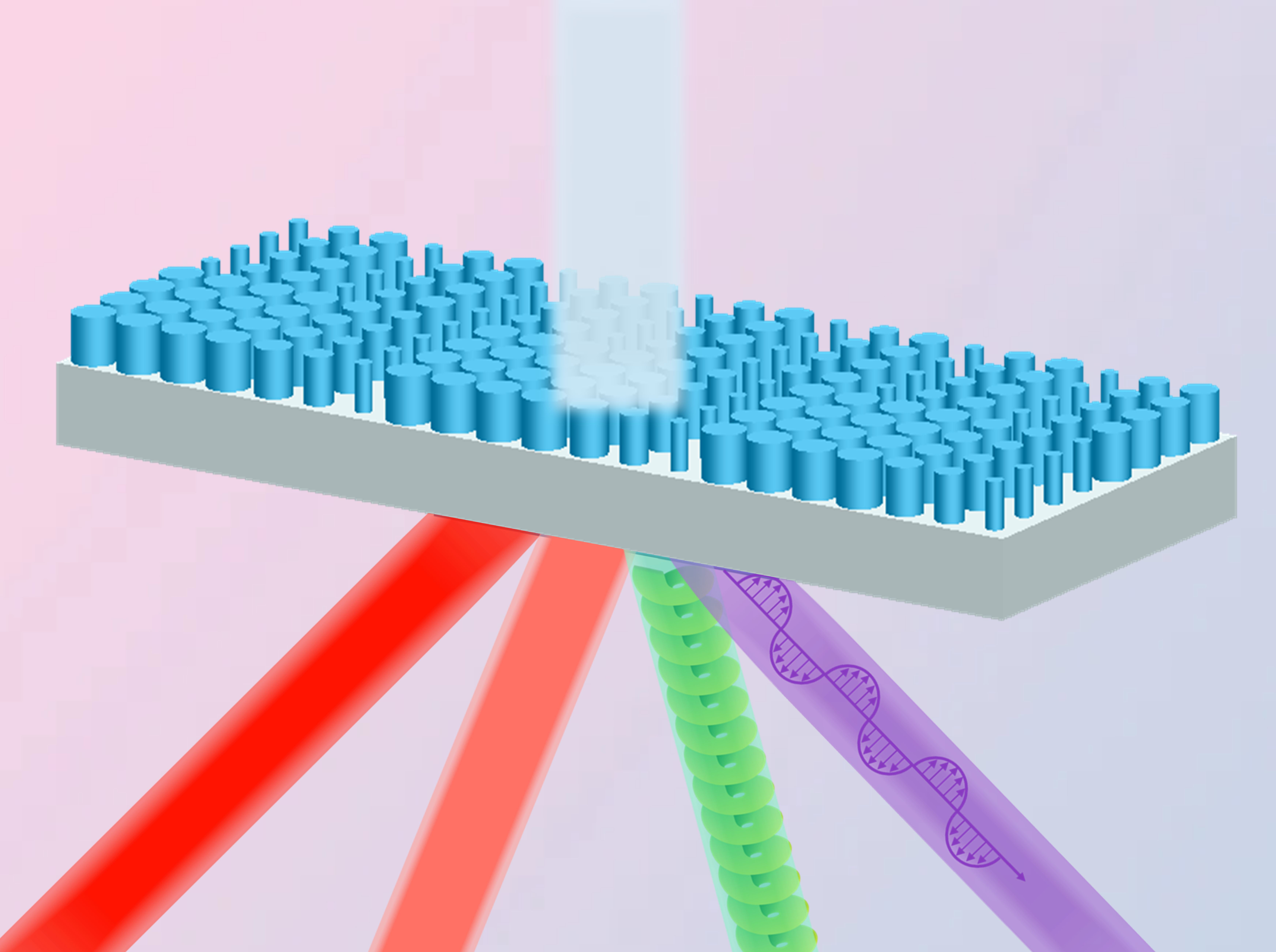
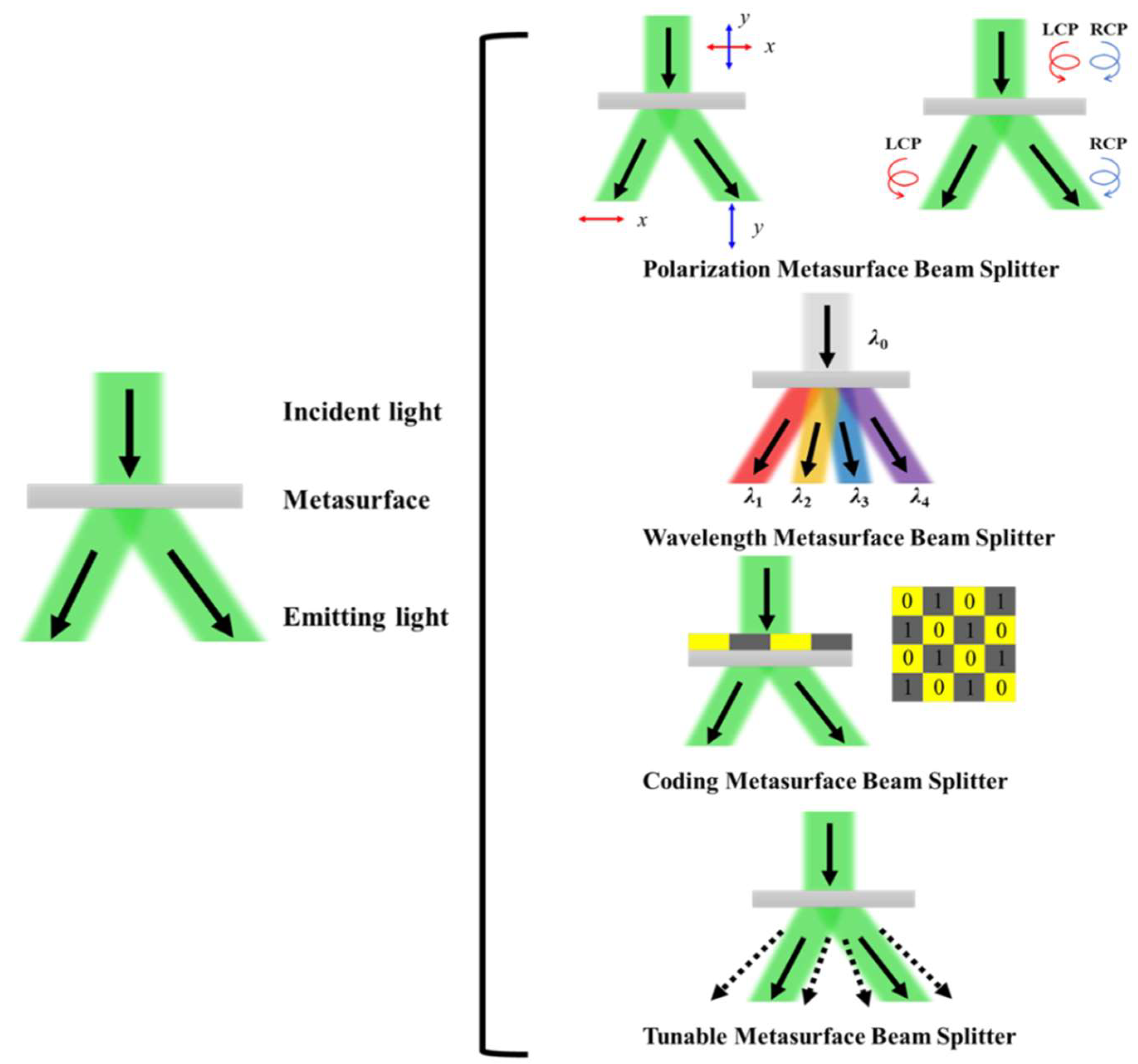
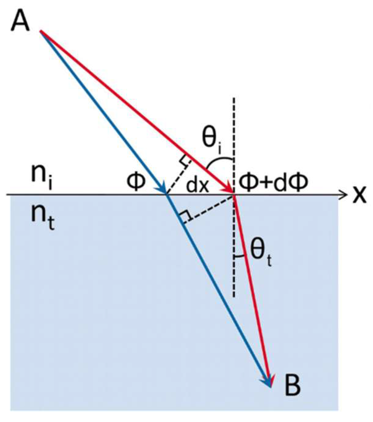
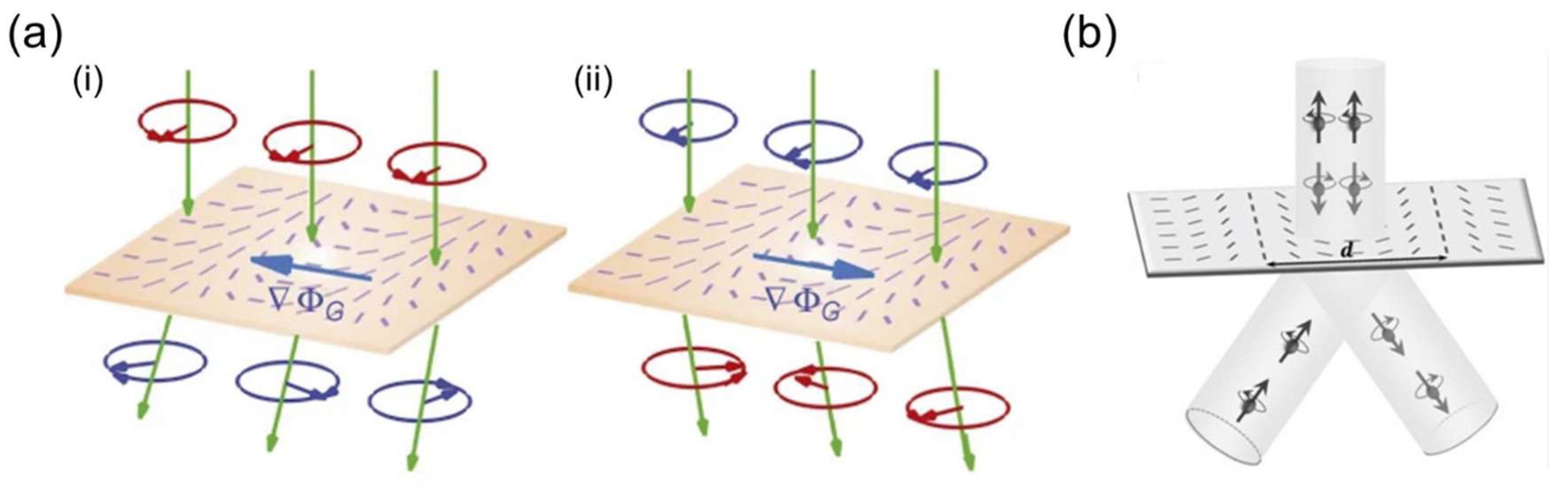
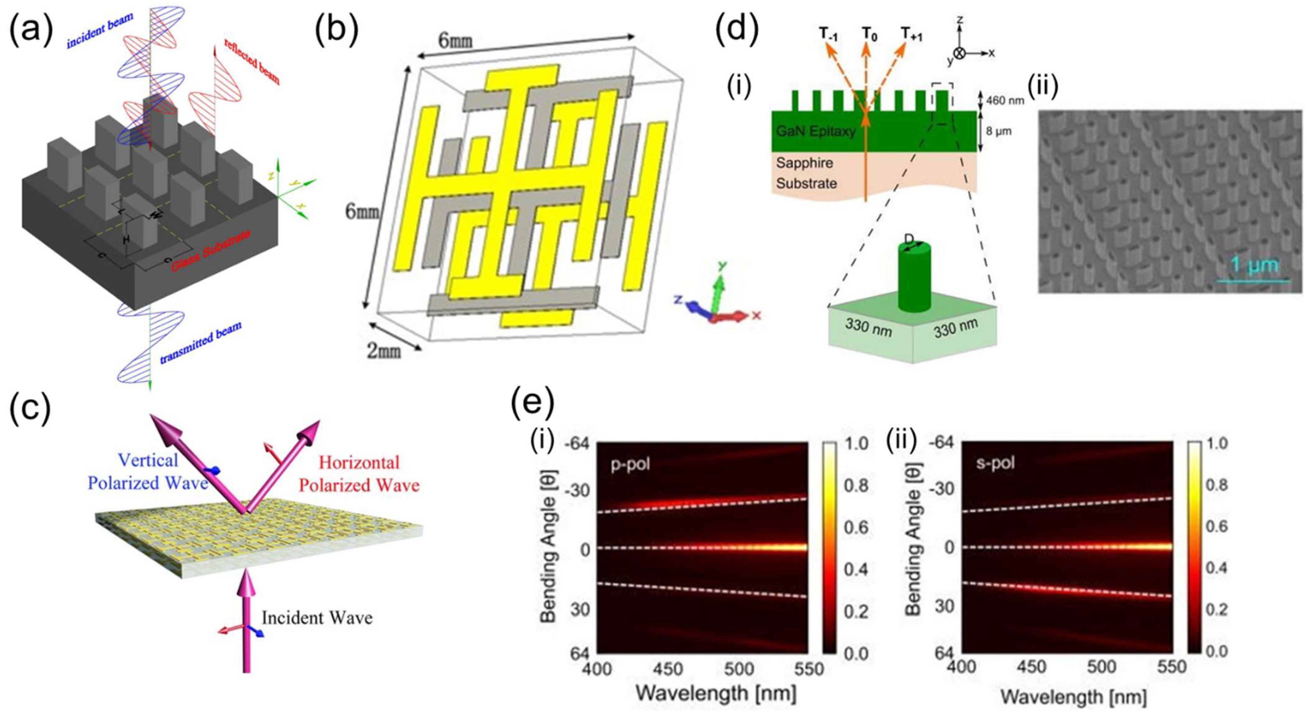
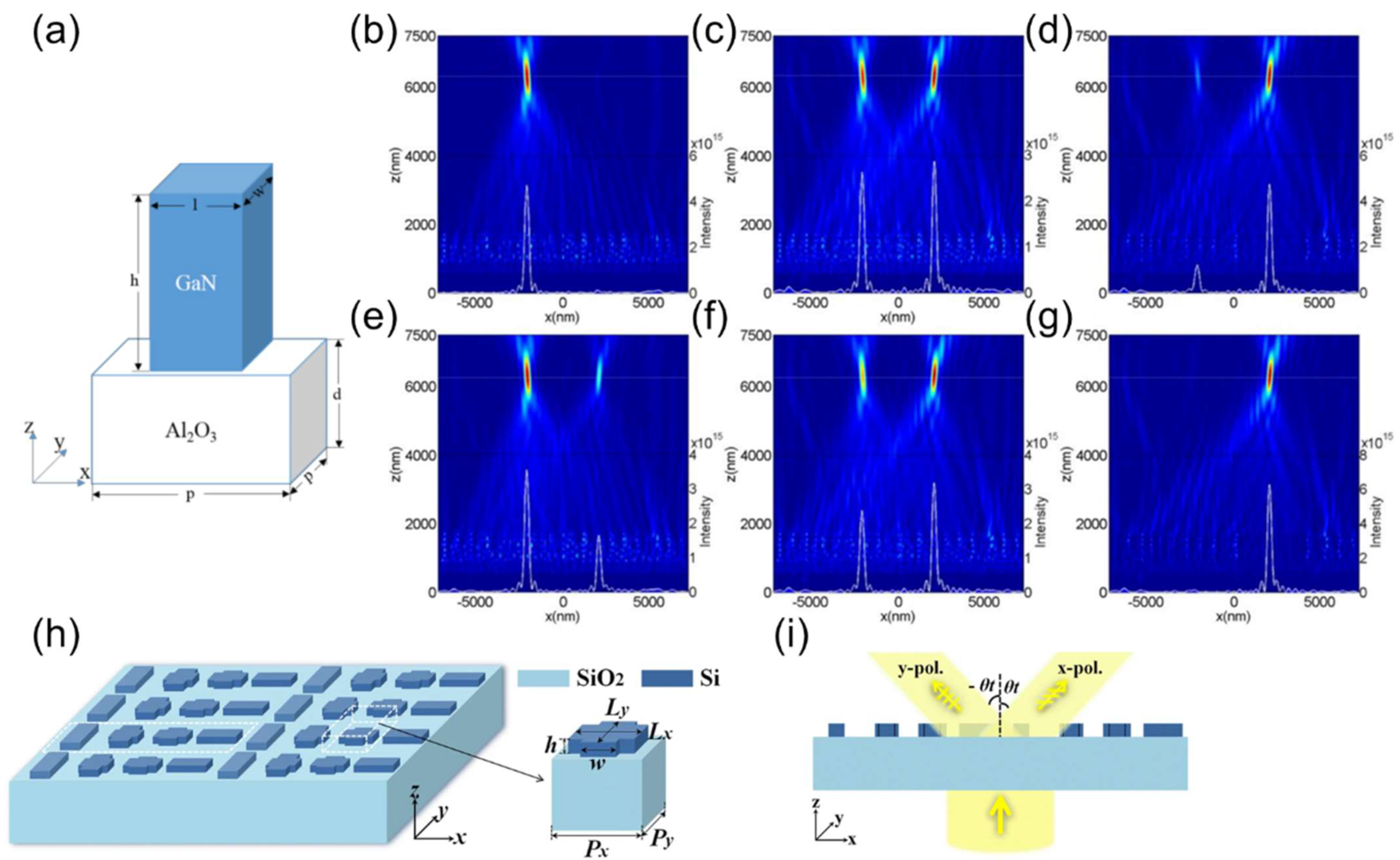
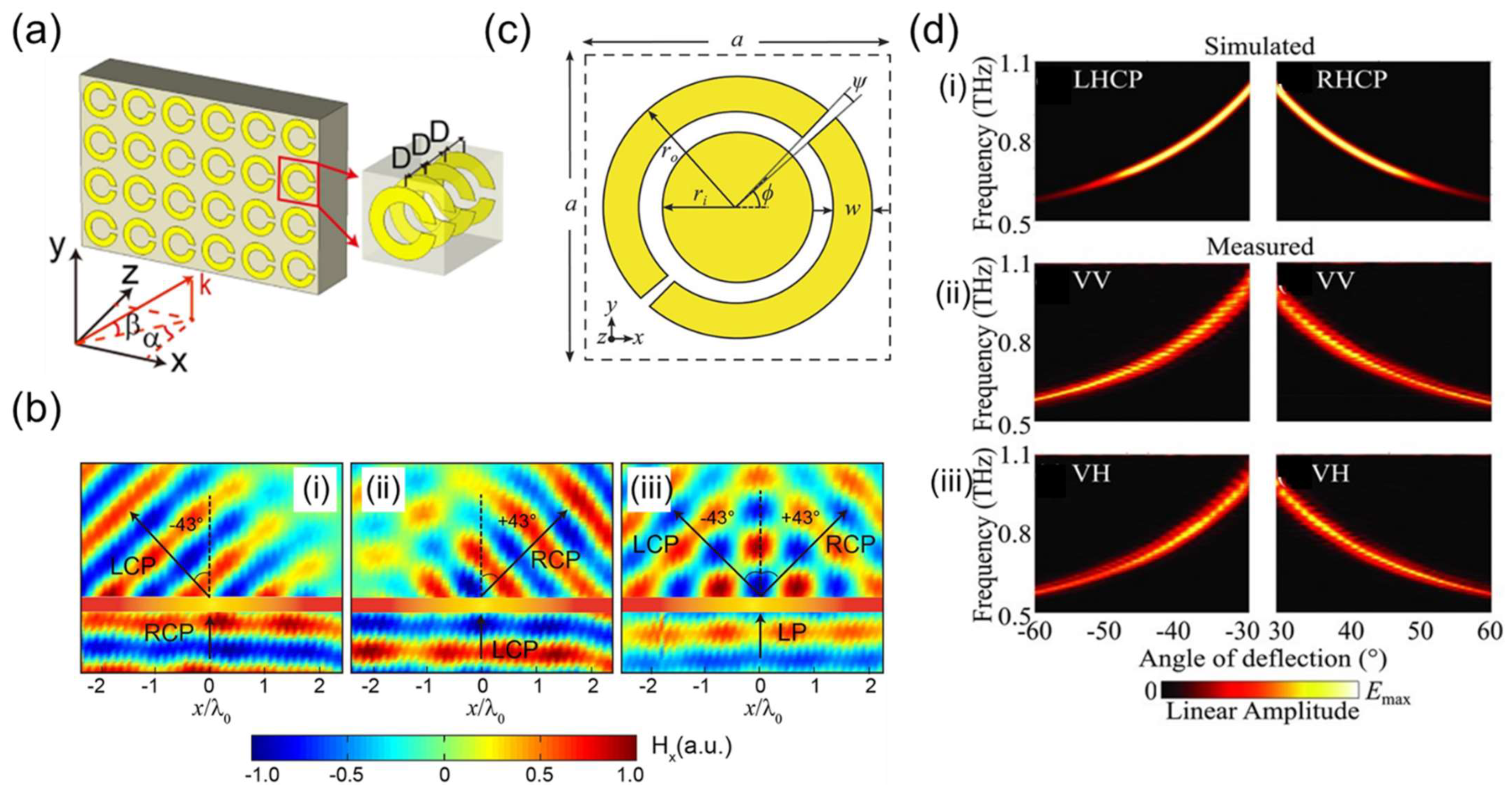
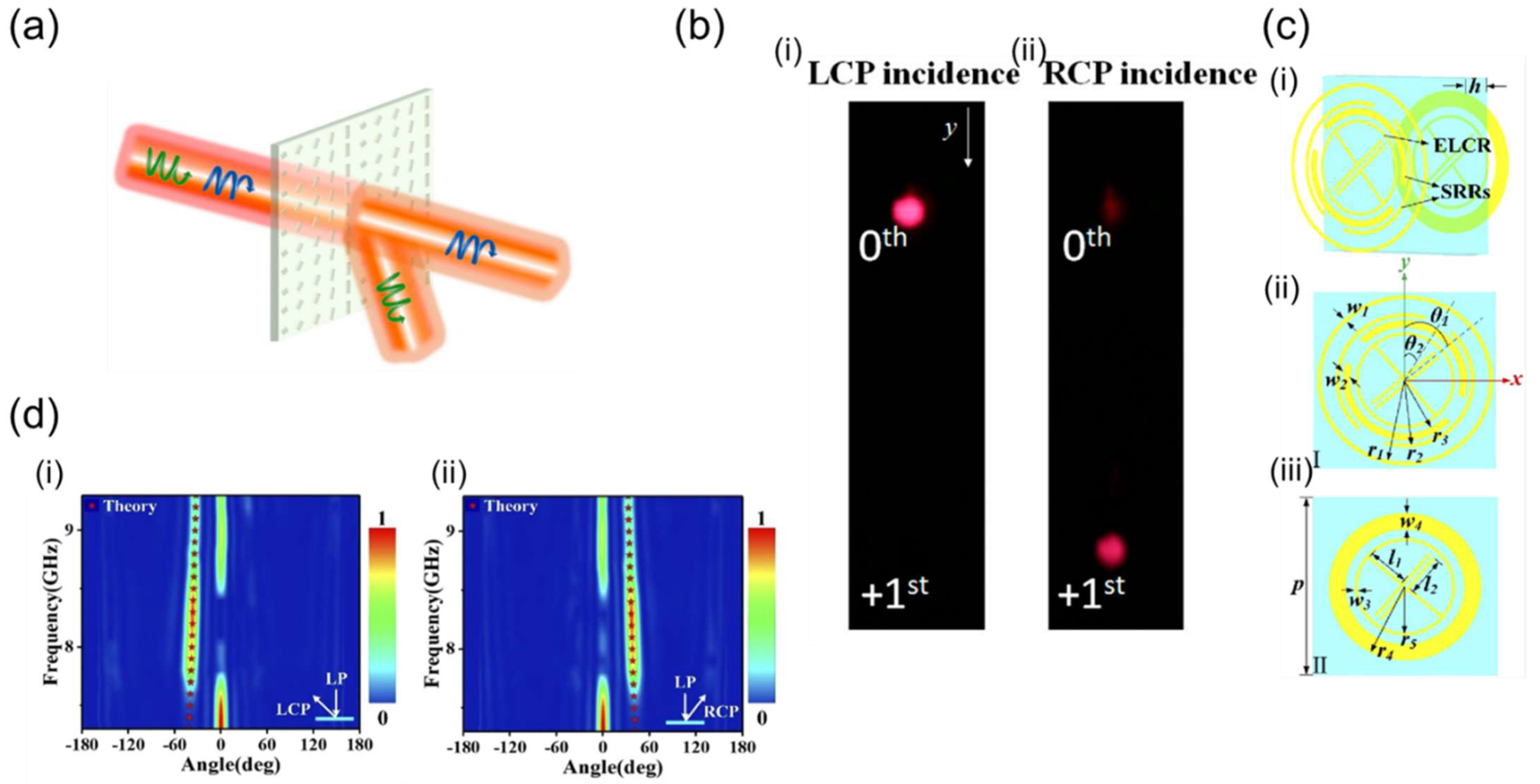
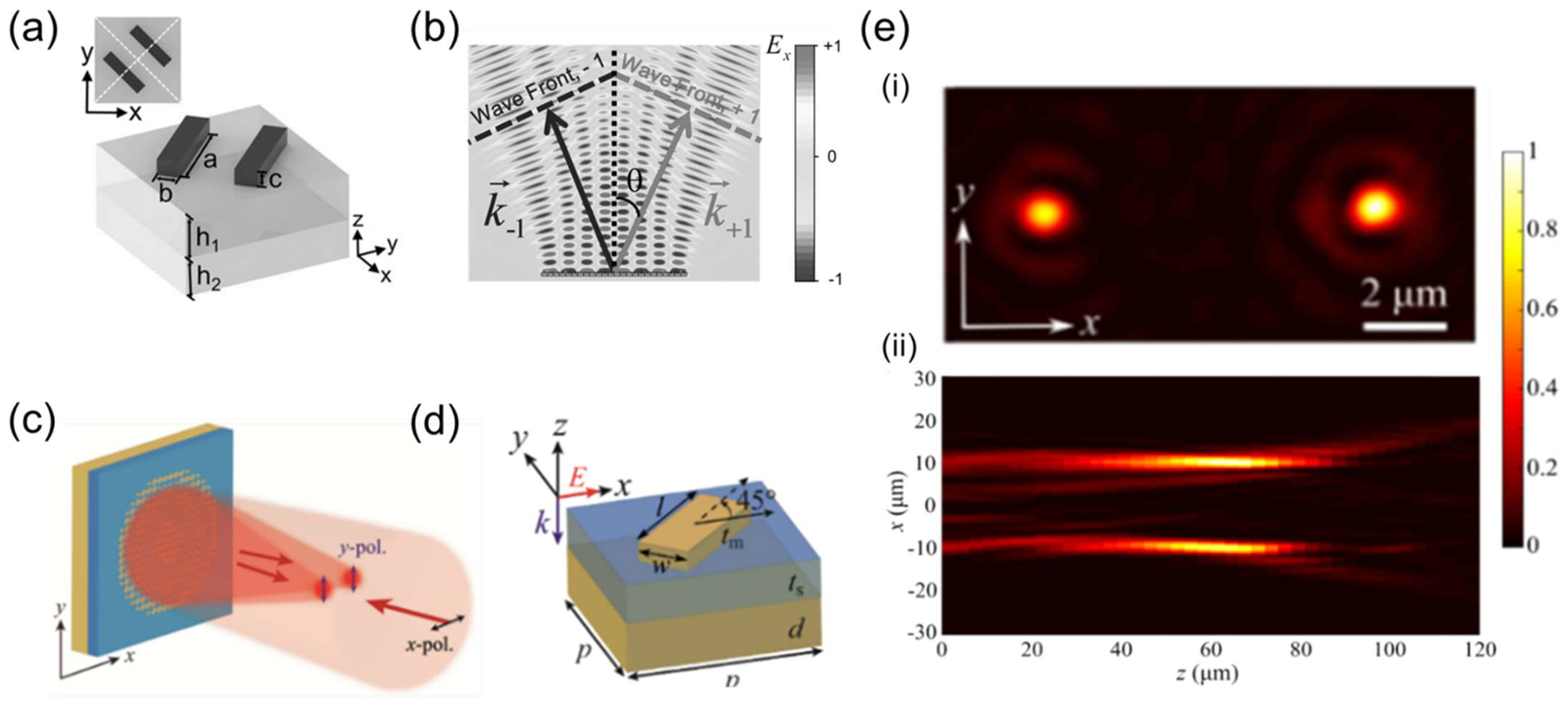
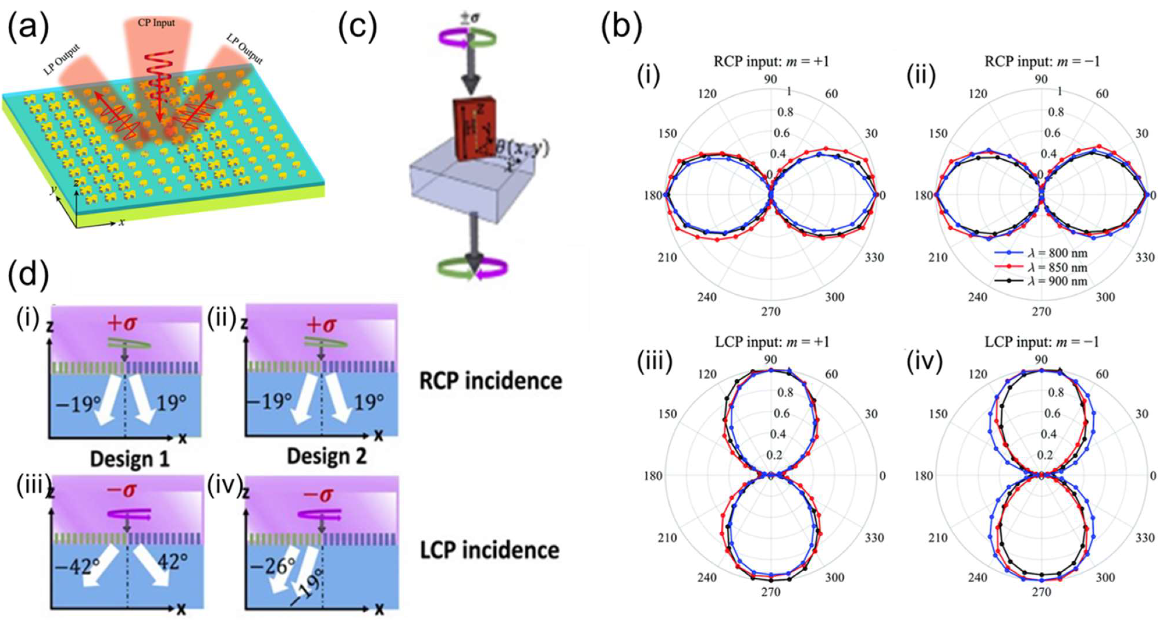
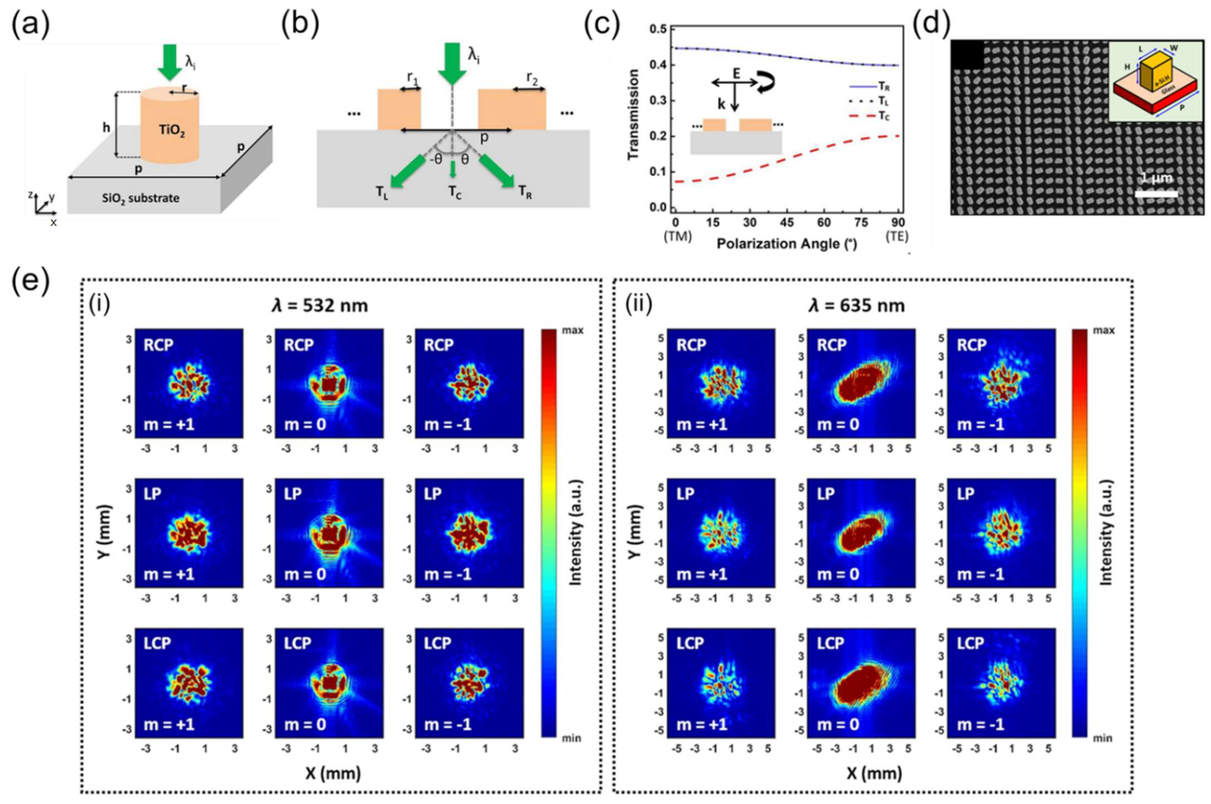
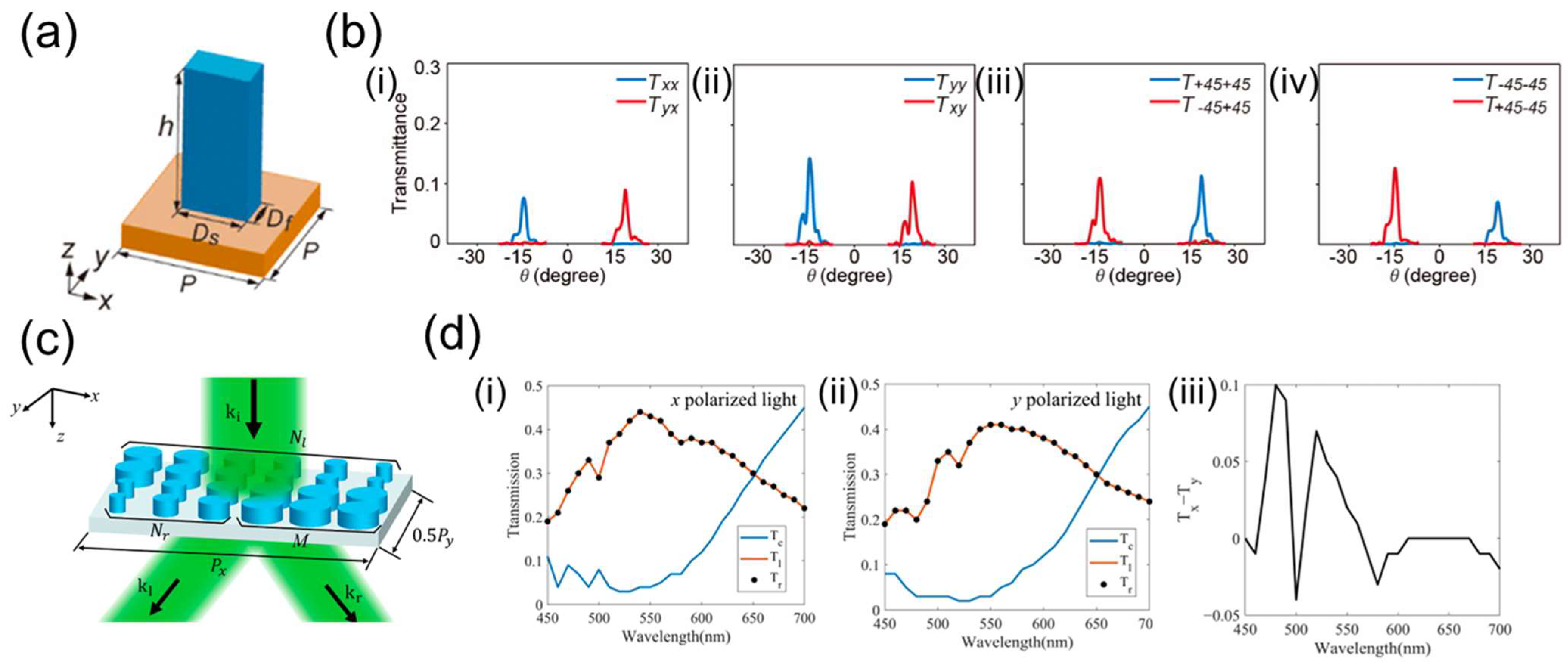
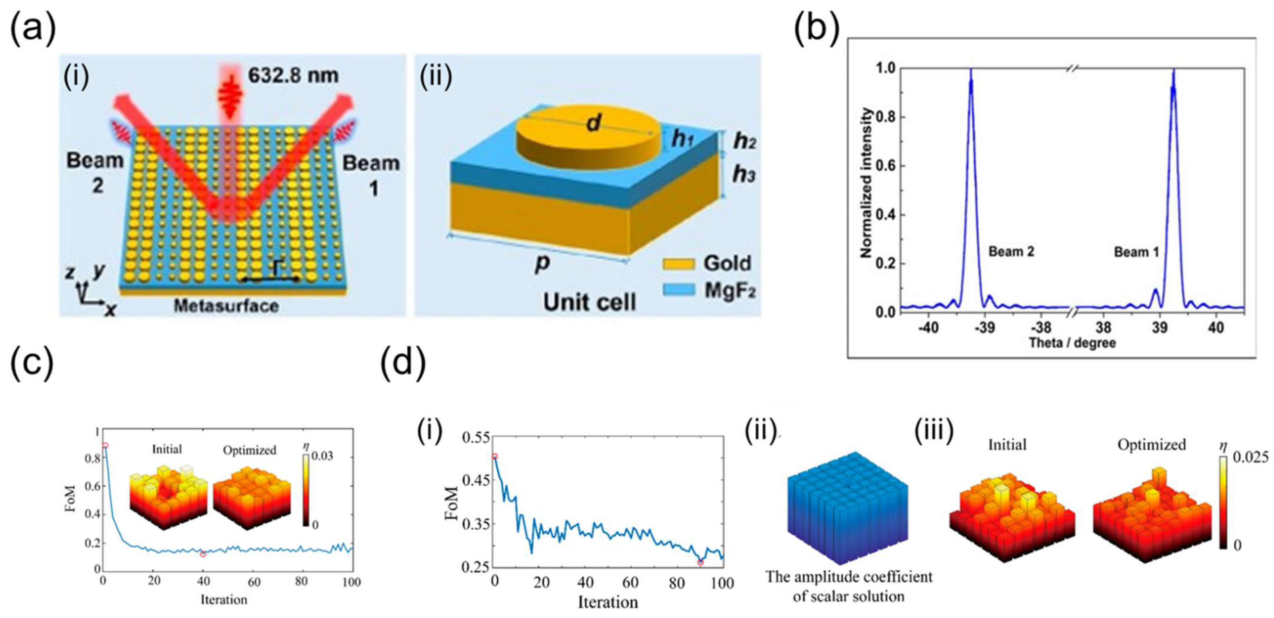
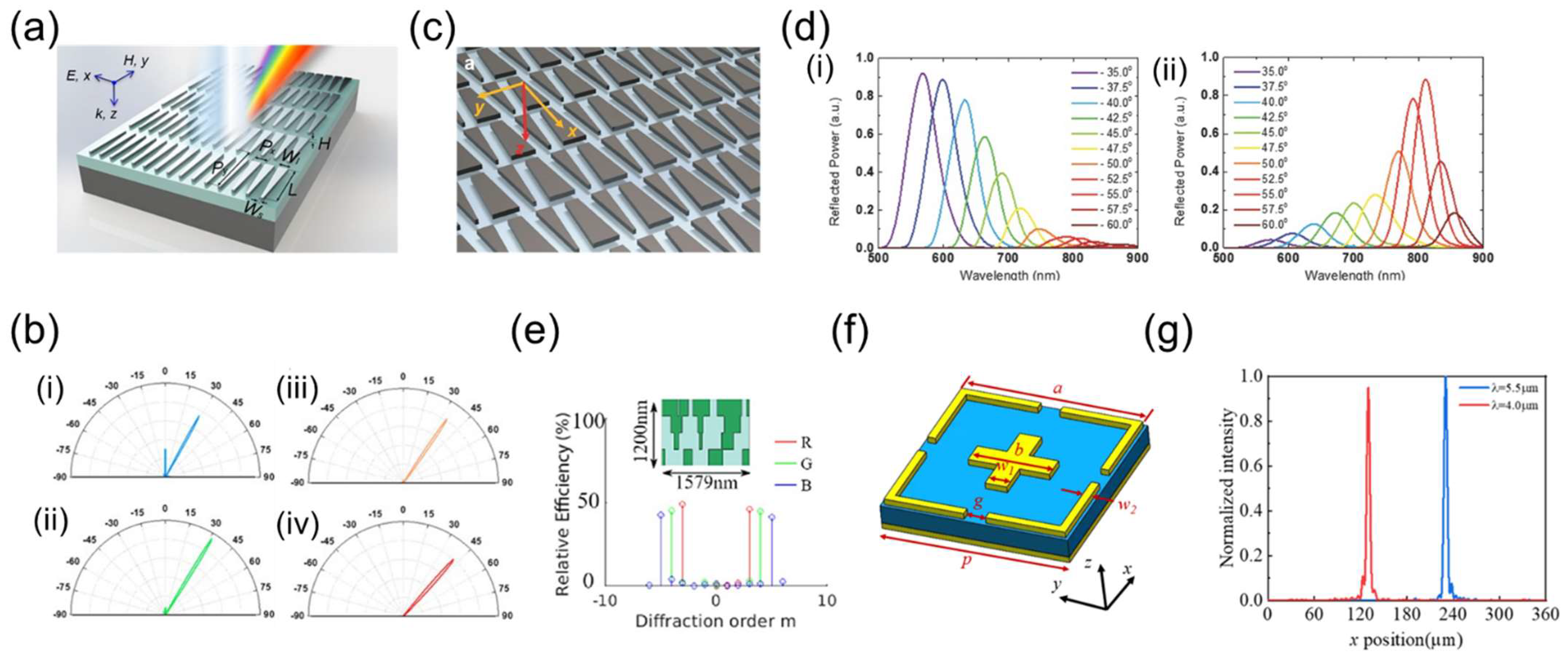
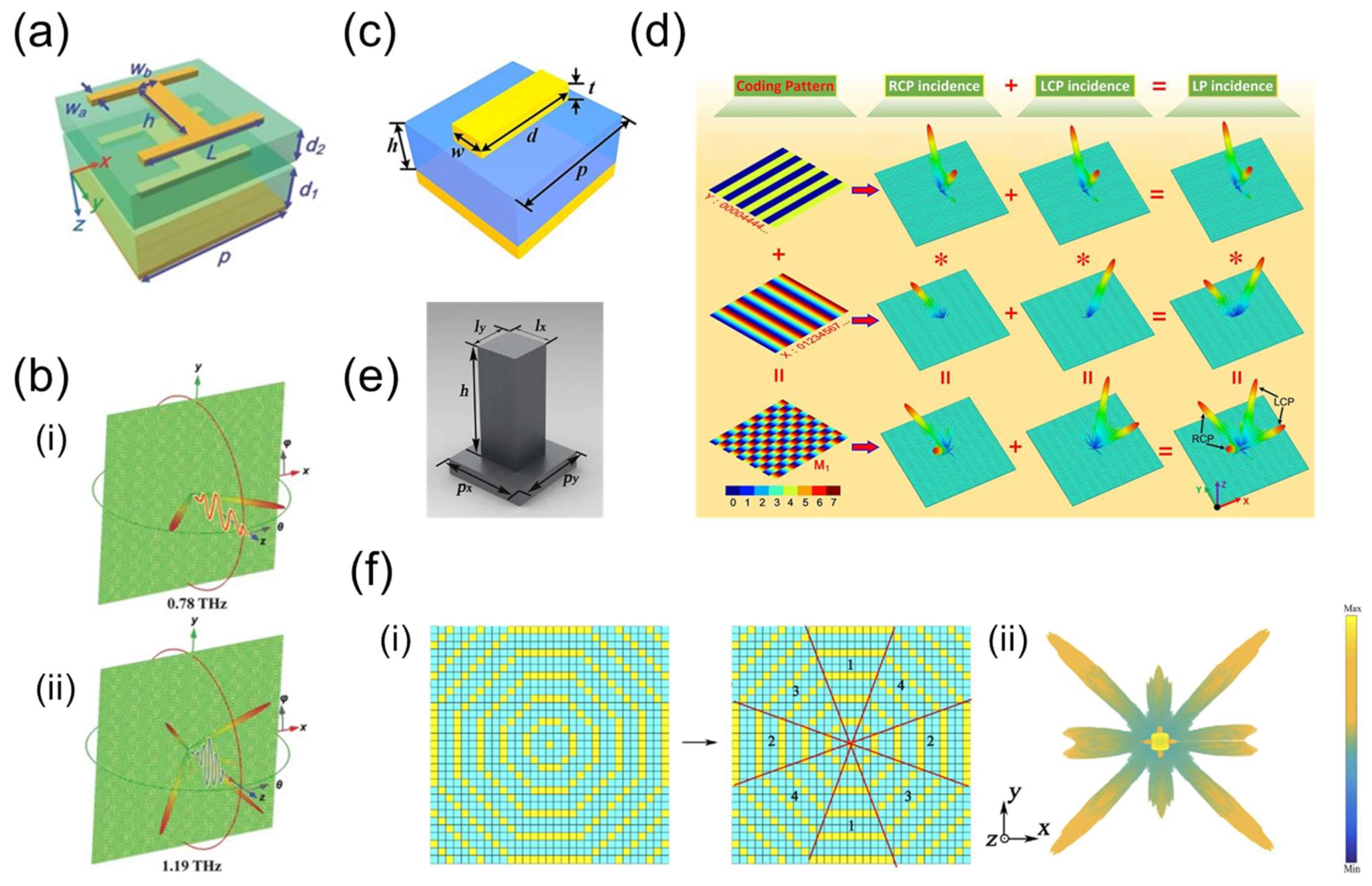
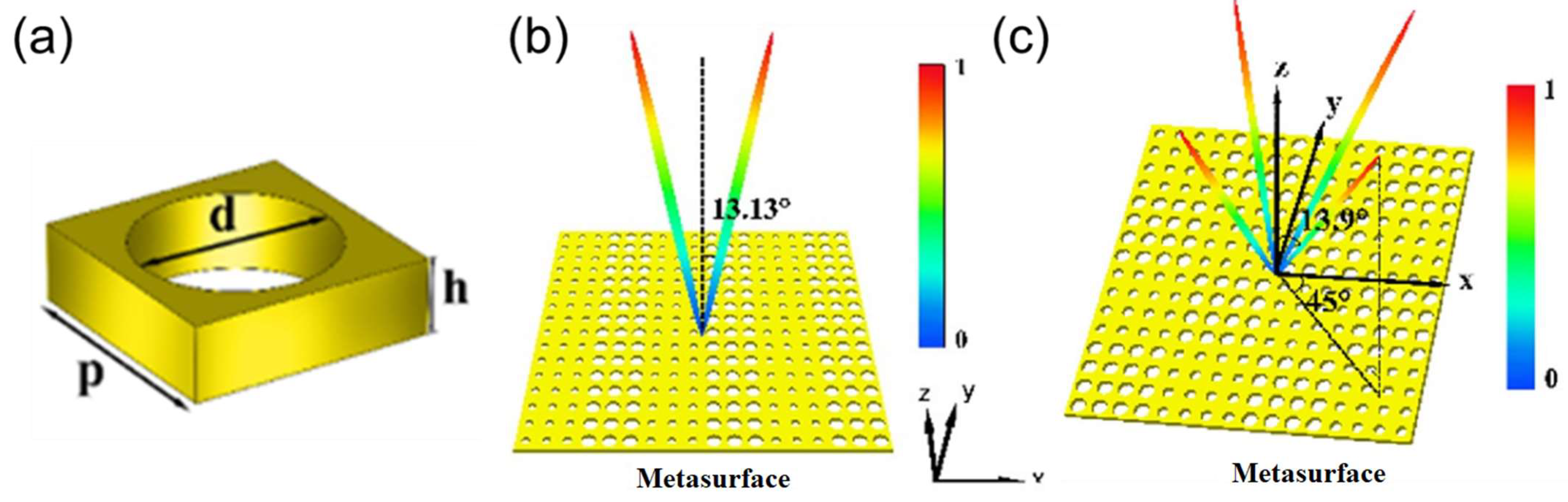
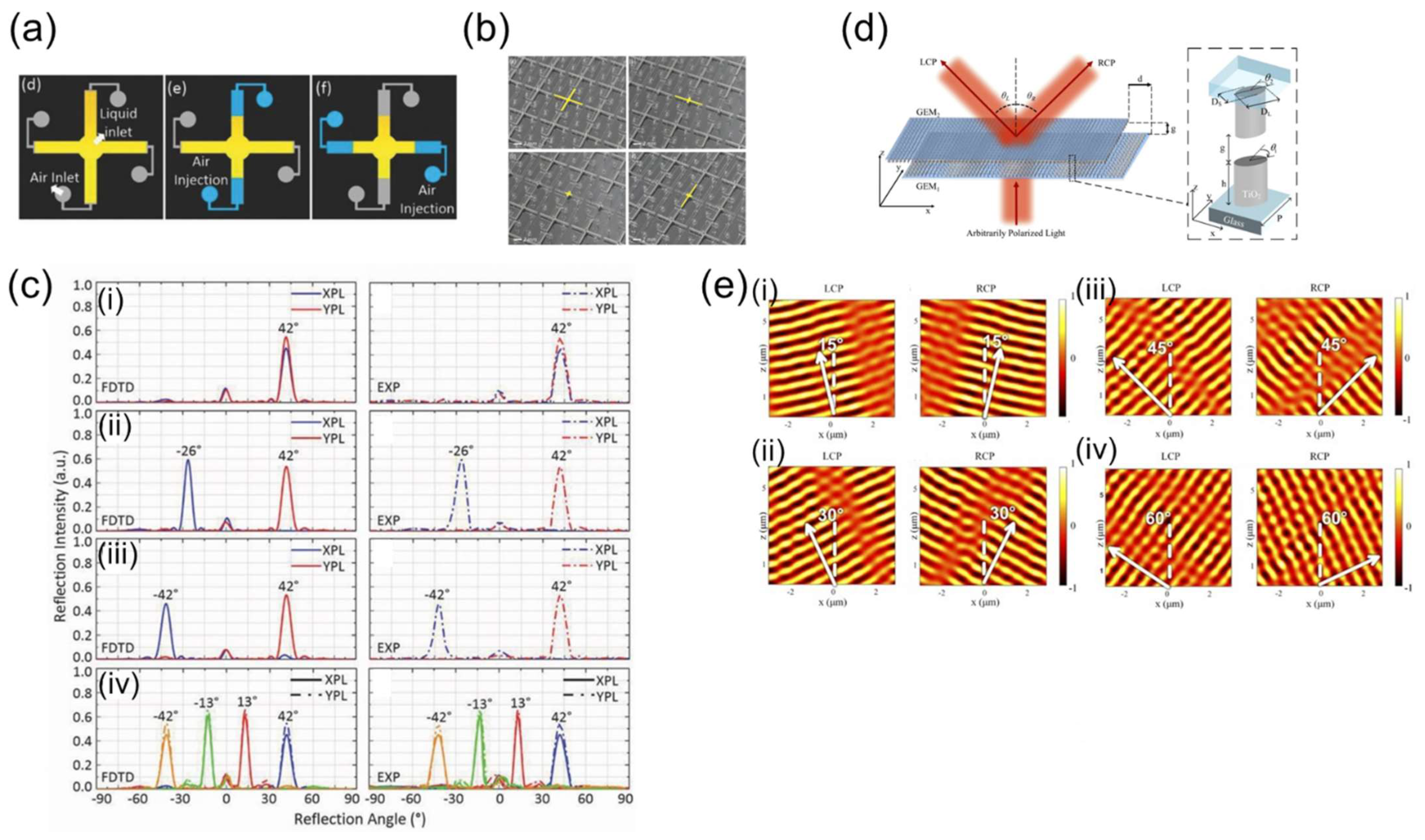
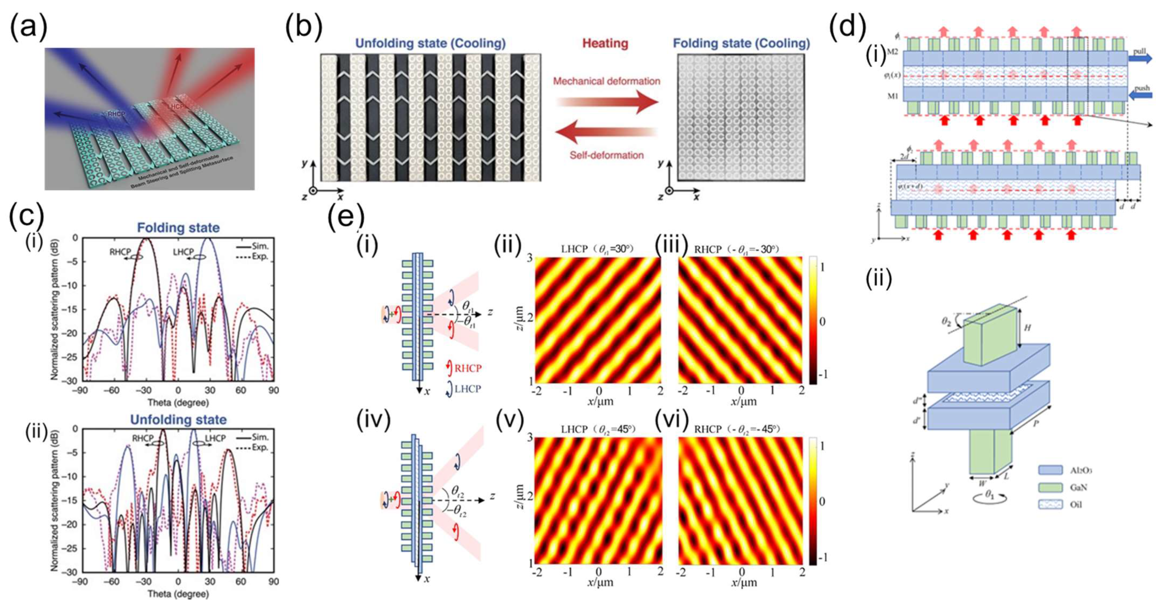
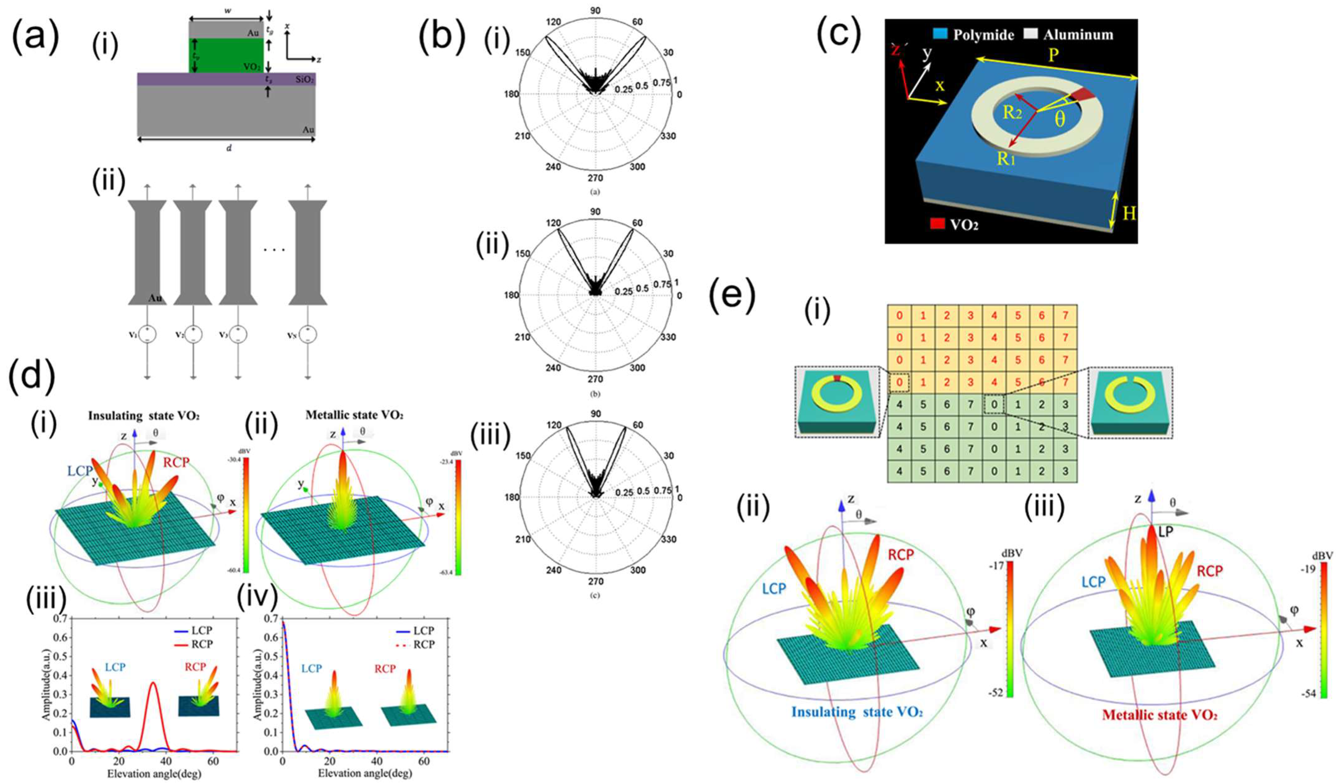
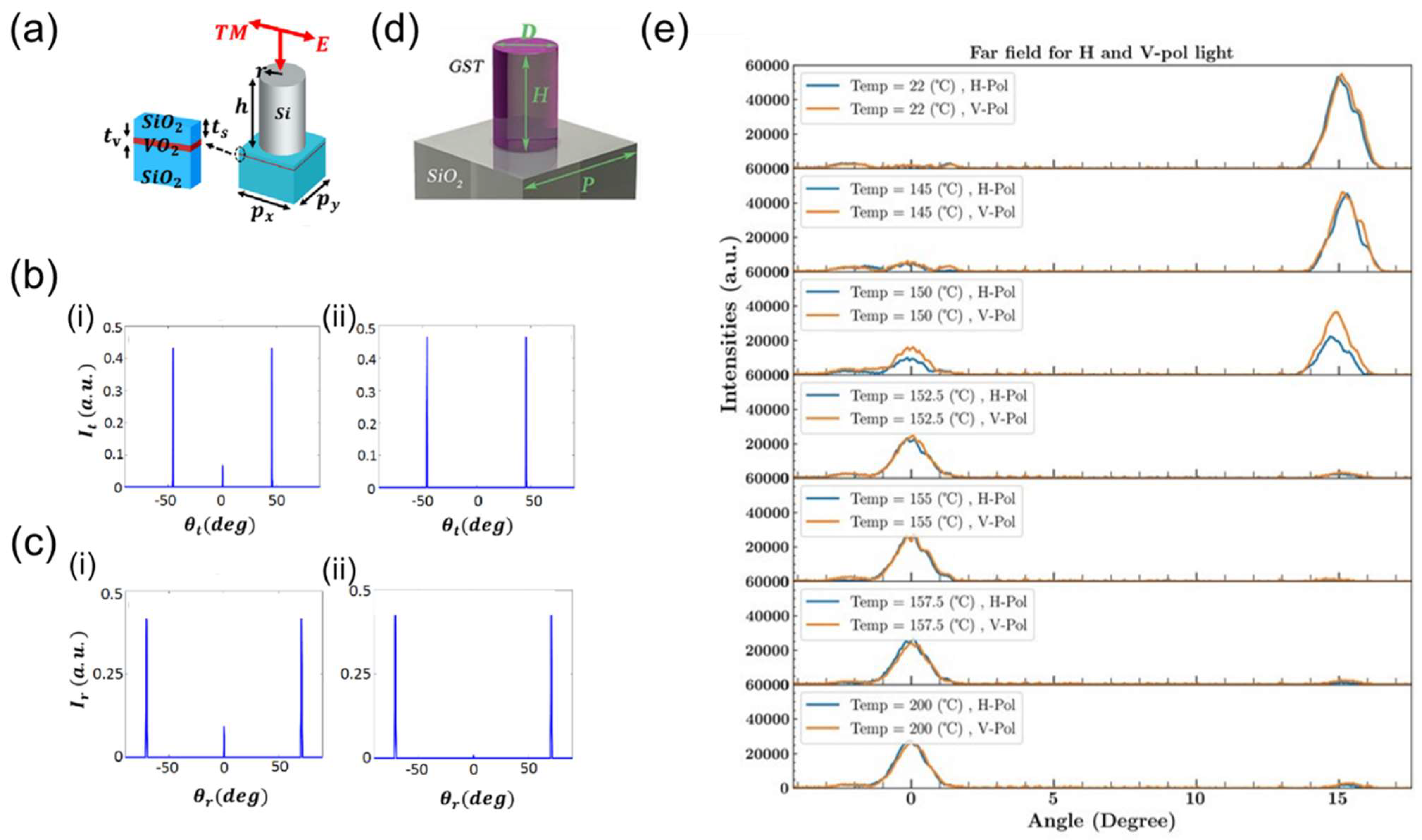
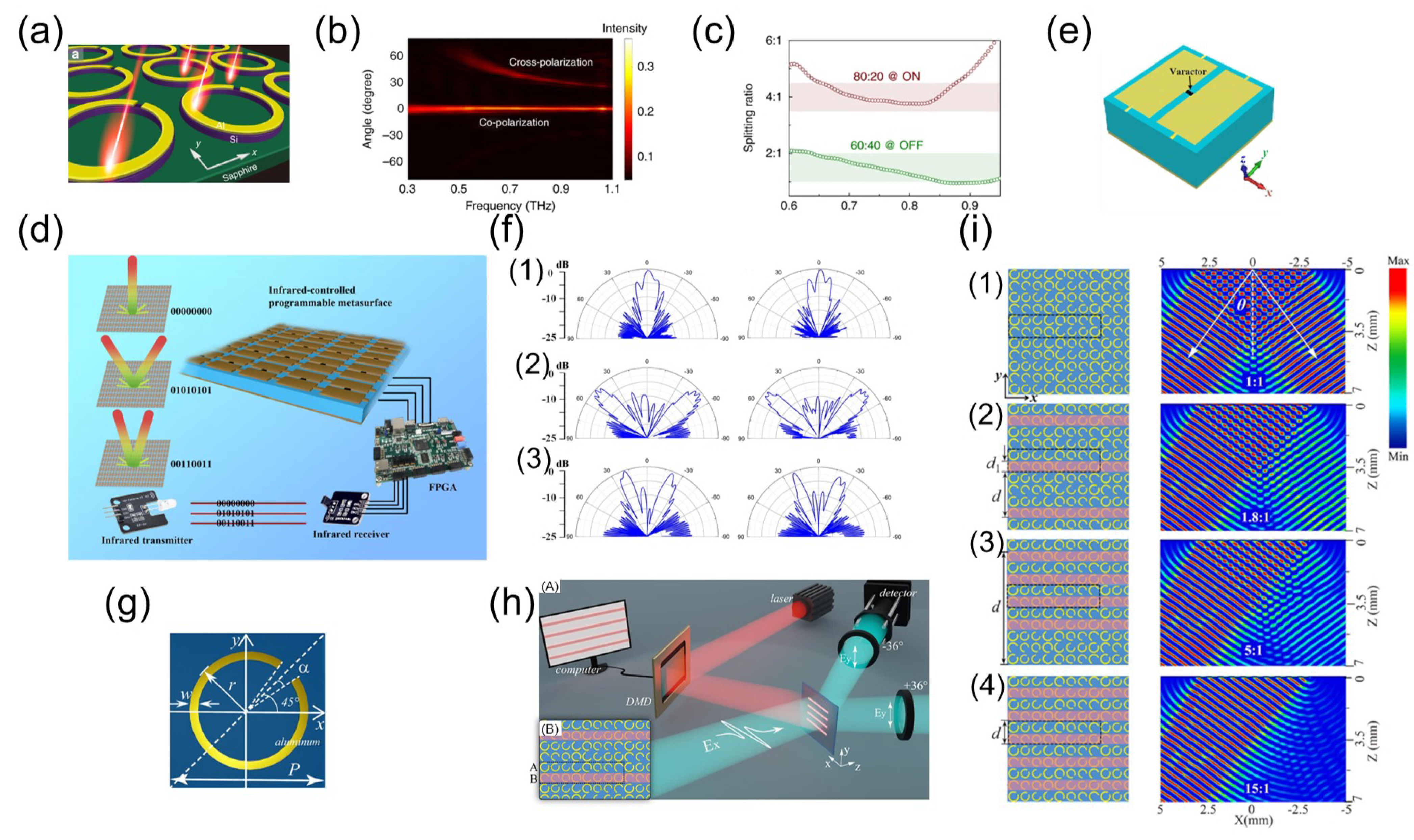
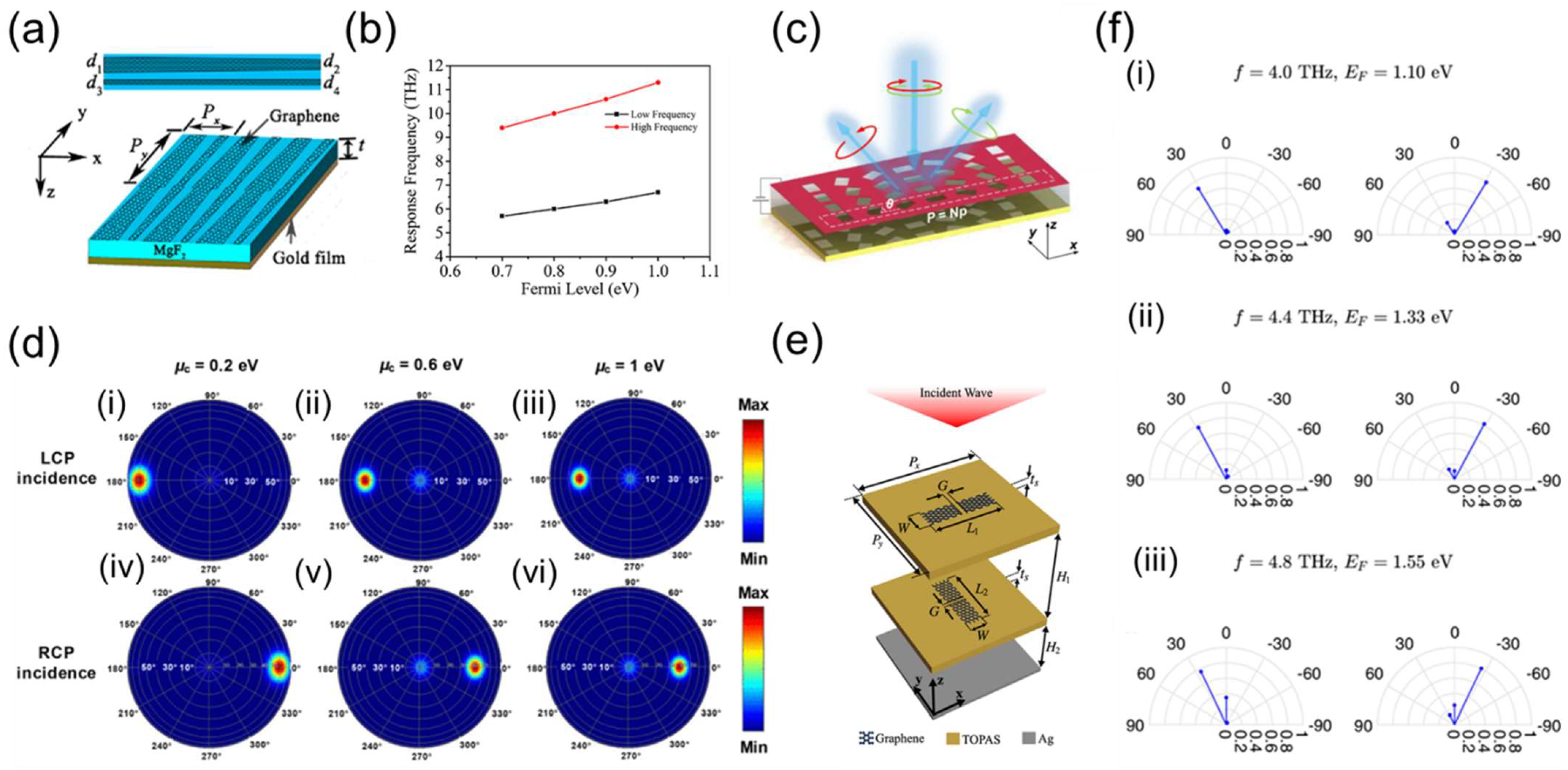
Table 1.
Parameters of circular linear metasurface beam splitters described in this section.
| Work | Material | Unit Size | Working Band | Splitting Angle | Research Type |
|---|---|---|---|---|---|
| [61] | Si | 720 × 720 × 490 nm | 1460~1625 nm | ±180° | Simulation |
| [62] | Metal | 240 × 240 × 2 mm | 9 GHz | ±45° | Simulation/Experiment |
| [63] | GaN | 330 × 330 × 460 nm | 430–470 nm | ±20° | Simulation/Experiment |
| [64] | GaN | 260 × 260 × 800 nm | 530 nm | ±14.7° | Simulation |
| [3] | Si | 200 × 200 × 260 nm | 579–584 nm | ±46.78° | Simulation |
Table 2.
Parameters of circular polarization metasurface beam splitters described in this section.
| Work | Material | Unit Size | Working Band | Splitting Angle | Research Type |
|---|---|---|---|---|---|
| [5] | Si | 3 × 0.5 × 1.5 μm | 974 nm | ±19° | Simulation/Experiment |
| [86] | Cu | 7 × 7 × 9 mm | 11 GHz | ±43° | Simulation/Experiment |
| [87] | Au | 120 × 120 × 200 μm | 0.58–1.00 THz | ±30°–±60° | Simulation/Experiment |
| [4] | Si | 400 × 400 × 420 nm | 730–830 nm | / | Simulation/Experiment |
| [88] | Metal | 10 × 10 × 3 mm | 8.3 GHz | ±37° | Simulation/Experiment |
Table 3.
Parameters of polarization-sensitive metasurface beam splitters described in this section.
| Work | Material | Unit Size | Working Band | Splitting Angle | Research Type |
|---|---|---|---|---|---|
| [97] | Ag | 500 × 500 × 310 nm | 1000–1400 nm | ±27.82° | Simulation/Experiment |
| [98] | Metal | 120 × 120 × 175 μm | 0.8–1.4 THZ | ±10.1°–±18.1° | Simulation/Experiment |
| [99] | Au | 550 × 550 × 320 nm | 850 nm | / | Simulation/Experiment |
| [100] | Au | 300 × 300 × 230 nm | 750–950 nm | ±28.2° | Simulation/Experiment |
| [101] | Si | 400 × 400 nm | 780 nm | ±19° (RCP)±42° (LCP) | Simulation |
Table 4.
Parameters of polarization-insensitive metasurface beam splitters described in this section.
Table 4.
Parameters of polarization-insensitive metasurface beam splitters described in this section.
| Work | Material | Unit Size | Working Band | Splitting Angle | Research Type |
|---|---|---|---|---|---|
| [109] | Si | 150 × 150 × 200 μm | 0.6–1.0 THz | ±28.43° | Simulation/Experiment |
| [110] | TiO2 | 250 × 250 × 600 nm | 532 nm | ±46.8° | Simulation |
| [111] | a-Si: H | 240 × 240 × 300 nm | 532/635 nm | ±24°/±28.5° | Simulation/Experiment |
| [112] | Si | 150 × 150 × 200 μm | 1.0 THz | 19.84°/−14.03° | Simulation |
| [113] | TiO2 | 250 × 250 × 600 nm | 532 nm | ±12°–±29.1° | Simulation |
Table 5.
Parameters of non-polarizing metasurface beam splitters described in this section.
| Work | Material | Unit Size | Working Band | Splitting Angle | Research Type |
|---|---|---|---|---|---|
| [120] | Au | 250 × 250 × 230 nm | 632.8 nm | ±39.26° | Simulation/Experiment |
| [121] | Si | 4.6 × 4.6 μm | 940 nm | ±70° | Algorithm |
Table 6.
Parameters of wavelength metasurface beam splitters described in this section.
| Work | Material | Unit Size | Working Band | Splitting Angle | Research Type |
|---|---|---|---|---|---|
| [122] | Ag | 1000 × 200 × 30 nm | 480/520/560/660 nm | 28°/31°/34°/41° | Simulation/Experiment |
| [123] | Ag | 1000 × 450 × 40 nm | 460/560/780 nm | 0°/−35°/55° | Simulation/Experiment |
| [124] | TiO2 | 1200 × 1579 × 300 nm | 720/540/432 nm | / | Simulation/Algorithm |
| [125] | Au | 3 × 3 × 0.37 μm | 4.0/5.5 μm | 14.2°/−16.0° | Simulation |
Table 7.
Parameters of coding metasurface beam splitters described in this section.
| Work | Material | Unit Size | Working Band | Splitting Angle | Research Type |
|---|---|---|---|---|---|
| [128] | Au | 70 × 70 × 25 μm | 1.19 THz | 64.2° | Simulation/Experiment |
| [130] | Cu | 6 × 6 × 2 mm | 15 GHz | 24.6° | Simulation/Experiment |
| [131] | Si | 150 × 150 × 200 μm | 1.0 THz | / | Simulation |
| [132] | Metal | 45 × 45 × 25 μm | 1.0 THz | 24.6°/6° | Simulation |
| [133] | Cu | 220 × 220 × 400 μm | 1.0 THz | ±13.13°/13.9° | Simulation/Experiment |
Table 8.
Parameters of mechanical systems control tunable metasurface beam splitters described in this section.
Table 8.
Parameters of mechanical systems control tunable metasurface beam splitters described in this section.
| Work | Material | Unit Size | Working Band | Splitting Angle | Research Type |
|---|---|---|---|---|---|
| [138] | Liquid Metal | 7 × 7 × 0.1 mm | 15 GHz | ±42°/±13°/−26° | Simulation/Experiment |
| [139] | TiO2 | 250 × 250 × 600 nm | 473–633 nm | ±15°/±30°/±45°/±60° | Simulation |
| [140] | Ag | 7.5 × 7.5 × 2.6 mm | 10 GHz | ±14°/±30° | Simulation/Experiment |
| [141] | GaN | 200 × 200 × 600 nm | 440 nm | ±30°/±45° | Simulation |
Table 9.
Parameters of tunable metasurface beam splitters for phase change materials described in this section.
Table 9.
Parameters of tunable metasurface beam splitters for phase change materials described in this section.
| Work | Material | Unit Size | Working Band | Splitting Angle | Research Type |
|---|---|---|---|---|---|
| [144] | Au/VO2 | 387.5 × 387.5 × 160 nm | 1550 nm | ±24°/±30°/±42° | Simulation |
| [145] | Al/VO2 | 140 × 140 × 36 μm | 0.67 THz | 34.4° | Simulation |
| [146] | Si/SiO2/VO2 | 150 × 150 × 192 μm | 0.7 THz | ±45.54°/±70.63° | Simulation |
| [147] | GST | 545 × 545 × 650 nm | 1550 nm | 15° | Simulation/Experiment |
Table 10.
Parameters of lighting control tunable metasurface beam splitters described in this section.
Table 10.
Parameters of lighting control tunable metasurface beam splitters described in this section.
| Work | Material | Unit Size | Working Band | Splitting Angle | Research Type |
|---|---|---|---|---|---|
| [148] | Al/Si | 80 × 80 × 460.6 μm | 0.6–1.0 THz | 51°−28° | Simulation/Experiment |
| [149] | Cu | 13 × 13 × 3.036 mm | 4.10/4.35 GHz | ±45°/±20° | Simulation/Experiment |
| [150] | Al | 80 × 80 × 500 μm | 0.8 THz | ±36° | Simulation |
Table 11.
Parameters of voltage control tunable metasurface beam splitters described in this section.
Table 11.
Parameters of voltage control tunable metasurface beam splitters described in this section.
| Work | Material | Unit Size | Working Band | Splitting Angle | Research Type |
|---|---|---|---|---|---|
| [151] | MgF2/Graphene | 90 × 12 × 4.5 μm | 5.7–6.7/9.4–11.3 THz | −35°/+25° | Simulation |
| [152] | Graphene | 80 × 65 × 17 μm | 0.45–0.65 THz | −60°–−40° | Simulation |
| [153] | Graphene | 24 × 24 × 1 μm | 4.0–4.8 THz | ±31° | Simulation |
Publisher’s Note: MDPI stays neutral with regard to jurisdictional claims in published maps and institutional affiliations. |
© 2022 by the authors. Licensee MDPI, Basel, Switzerland. This article is an open access article distributed under the terms and conditions of the Creative Commons Attribution (CC BY) license (https://creativecommons.org/licenses/by/4.0/).
Share and Cite
MDPI and ACS Style
Shen, Z.; Huang, D. A Review on Metasurface Beam Splitters. Nanomanufacturing 2022, 2, 194-228. https://doi.org/10.3390/nanomanufacturing2040014
AMA Style
Shen Z, Huang D. A Review on Metasurface Beam Splitters. Nanomanufacturing. 2022; 2(4):194-228. https://doi.org/10.3390/nanomanufacturing2040014
Chicago/Turabian StyleShen, Zhe, and Dingxin Huang. 2022. "A Review on Metasurface Beam Splitters" Nanomanufacturing 2, no. 4: 194-228. https://doi.org/10.3390/nanomanufacturing2040014