Article

A Comprehensive Numerical Modeling Study for Parameter Optimization and Slope Stability Analysis in the Baganuur Lignite Coal Mine

Department of Geosciences, Geotechnology and Materials Engineering for Resources, Graduate School of International Resource Sciences, Akita University, Akita 0108502, Japan
*
Author to whom correspondence should be addressed.
Mining 2023, 3(4), 755-772; https://doi.org/10.3390/mining3040041
Submission received: 16 October 2023 / Revised: 14 November 2023 / Accepted: 20 November 2023 / Published: 22 November 2023

Abstract

:
The “Baganuur” lignite coal mine is one of the biggest open cast mines in Mongolia. However, there is a huge challenge in managing the stability of its internal dump, which prevents the proper operation of the mine and has an impact on the economy. To solve the internal dump slope stability problem, this study focused on incorporating the inherent mechanical properties of the rock material to build numerical models of the internal dump. By applying two software programs from Rocscience (Phase2 and Slide) and four different methods, the finite element method, the Bishop method, the Janbu simplified method, and the Spencer simplified method, the current and improved internal dump parameters were numerically simulated and analyzed. Based on the properties of the rock, the LEM and FEM were used to determine the parameters that could have an impact on the stability of the internal waste dump. The impacts of the internal dump height, dip angle, and safety berm on these parameters were studied. This study covers several analytical methods for calculating safety factors. Based on the results of the numerical simulation, it is determined that it is possible to increase the internal dump capacity by approximately 56% at a 50 m height and 28° dip angle and using a 15 m safety berm. Under similar conditions, this study presents an optimum SRF at 40 m height, 28° dip angle, and 5 m safety berm. Based on the numerical models, it is found that changes in the dip angle have a greater impact than changes in the dump height on the slope stability of an internal dump.

1. Introduction

The “Baganuur” lignite coal mine is in a rural area of Ulaanbaatar, Mongolia, at the boundary of the Central and Khentii provinces. The region has a humid and chilly climate due to its location in the southwest of the Khentii province, which is host to many mountains. “Baganuur” is one of Mongolia’s biggest lignite coal mines and this mine supplies 60% of the total demand for coal in Mongolia [1]. The current mining activity and constant supply of coal are two major factors in the steady rise in exports to both local and international markets. The negative effects of a loss of internal dump stability and safety concerns are worsening as open cast mining continues [2]. The failure of internal dumps is a complex problem. In addition to environmental considerations, it directly affects resource recovery, mine safety, and mining cost [3]. The operations in this mine have been hampered in recent years by an increase in landslides and collapses in most areas of the site. The lack of long-term monitoring of the geological environment in the mining area, as well as the lack of scientific research and experimentation, has led to a significant degradation of the mining environment despite the mining region’s rapid development. As a result, the threat to human life and technical and financial harm from open-pit mining are increasing. In geotechnical engineering, the numerical calculation method is frequently employed [3,4,5,6,7,8]. Computer software can be used to display a realistic slope, its geological surroundings, strata, and lithology, as well as whether or not there is a joint surface, and analyze the failure mechanism in light of the outcomes of simulation calculations [9].
Slope stability analysis is crucial for preventing the occurrence of dump slope failure. It helps in understanding the parameters that control the dynamics of dump slopes. The factor of safety (FS) is an index of stability applied in geotechnical models to determine the stability of a dump slope [10].
The most popular methods for slope stability analysis are the finite element method (FEM) [11] and the finite difference method (FDM) [12]. The FEM model delivers a piece-wise approximation to a problem where an assembly of elements subdivides the geometry along the boundaries, whereas the FDM gives a point-wise approximation to a problem where an array of grid points subdivides the geometry along each coordinate axis. By discretizing the domain with elements of a chosen shape and assembling them into the complete system, the FEM is able to solve the governing equations. The FDM cannot be utilized to solve issues with significant strain or deformation; instead, it is mostly employed to solve fluid dynamics and heat transport problems, frequently with fixed boundaries. The FEM provides additional benefits for handling issues with significant deformation and can be applied to almost any engineering issue involving intricate geometries and material mixtures [13].
In the critical limit equilibrium state of a slope, the maintenance of slope stability depends on the contributions of different strength parameters to each other. This implies that the strength parameters are not concurrently diminished. Therefore, the limit equilibrium (LE) stress methodology has been implemented in research to evaluate the stability of slopes through the utilization of the double strength reduction (DSR) approach [14].
Several numerical simulations have been developed, including “Rocscience Phase2” [15], “Rocscience Slide” [16], “GeoStudio” [17], “Hyrcan” [18], “Plaxis 2D” [19], and “GeoSlope” [20]. “Rocscience Phase2” is a 2D finite element program for calculating stresses and determining support, among other uses.
In this study, through the utilization of the previously mentioned methods, several factors that impact the stability of internal dumps are analyzed, the alterations in the dumps’ height are studied, and their impact on the factor of safety (FS) is reviewed via Plaxis 2D and GeoStudio [21,22]. The stabilization of FS through alterations in the slope angle, a factor that impacts the arrangement of internal dumps and the internal configuration of the mine, is also studied. The limit equilibrium method (LEM) in the Slide2 program is employed for this purpose [23].
The present research investigates the impact of specific factors on the stability of internal dumps through a comparison of different software and methods. Rocscience Phase2 software offers time and precision calculations and is superior for the investigation of rock properties, surface geometries, and groundwater conditions. For slope stability and foundation design, “Rocscience Phase2” can simulate the flow and plastic failure of materials with extreme accuracy. This has been acknowledged by numerous academics and this software offers significant benefits for resolving geotechnical engineering challenges [13,24,25,26]. In order to analyze the parameters of the quality of the specific process of slope deformation and failure, we use the “Rocscience Phase2” and “Slide2” numerical simulation methods to carry out numerical simulation analysis on the slope stability of the internal dump of the Baganuur lignite coal mine.
This study holds significant promise for the mining industry. By employing advanced numerical modeling techniques, this research addresses a critical aspect of mining operations: slope stability in lignite coal mining. The findings have the potential to improve industry practices by offering a comprehensive understanding of slope stability parameters, enabling more informed decision making and improved safety measures. The optimization of parameters also promises enhanced operational efficiency, cost savings, and reduced environmental impact.

2. Materials and Methods

To evaluate the existing stability of the internal waste dump, numerical solutions can be used to evaluate whether waste dump slopes respond to various circumstances.

2.1. Numerical Model

By using two-dimensional (2D) numerical software, scholars have carried out different studies and developed various models using different input factors such as internal dump height, dip angle, piezometric data of the internal dump failure, and predictions of ground motions. One of the most popular numerical model software is Rocscience Phase2. Hence, in geotechnical and mining engineering, “Rocscience Phase2” has been widely used for the design and analysis of tunnels, surface excavation, and ore extraction. Moreover, “Rocscience Phase2” may solve issues in the area of rock engineering by estimating the shear strength and displacement of the surrounding internal dump.
In this study, the finite element method was used to numerically analyze the dump slope. This continuum model was used to analyze complex geometries and model stress and predict the behavior of materials. In order to analyze slope stability issues and compare limit equilibrium methods to the same parameter models, this research study used the finite element method “Rocscience Phase2”.

2.1.1. Limit Equilibrium Method (LEM)

Shear strength is completely mobilized over the failure surface and overall slope, and each component is presumed to be in static equilibrium [27,28,29]. Using the LEM, researchers have proposed a number of methods for computing the factor of safety (FS) and failure surfaces. The most popular and widely utilized LEM approaches are the condensed Bishop method [30] and the condensed Janbu method [31].

2.1.2. Finite Element Method (FEM)

The FEM is a two-dimensional methodology based on plane strain and plane element formulations. A rock material model and the “Drucker–Prager” yield criterion and equation are used for consideration of shear yielding. A “Goodman-type” joint element is also included to simulate significant rock faults in the slope. “Courant” proposed the concept of piece-wise continuous functions in a subdomain. The most flexible numerical strategy for solving complex issues in rock mechanics is the FEM [32].
Through the use of the FEM, the soil continuum can be divided into discrete units, or “finite elements” [33]. The components are related to one another at their nodes and at the borders of the continuum. In geotechnical applications, the displacement technique is often used in FEM formulation. Results are frequently obtained as displacements, stresses, and strains at the nodal points. To establish the stability of dump slopes using the FEM, stresses, displacements, and the plasticity state inside the dump mass were computed using “Rocscience Phase2”, a two-dimensional finite element tool from “Rocscience v8.0”. This software computes plasticity, stress, strain, displacement, and yielding elements in addition to deformed borders, deformation vectors, and deformed boundaries [28].

2.2. Model Description

A 2D model was built in Phase2 according to the given geological profile (Figure 1). The internal waste dump slope’s location, parameters, and soil structure (Table 1) are shown in the figure alongside the model’s 2D dimension. An area 200 m long (x-axis), between 70 m and 290 m high (y-axis), with two major types of soil and a coal operation area, is included in the numerical simulation model (Figure 2). Furthermore, a plastic model was developed to simulate the initial stress state.

2.3. Material Properties

This work considered only two-dimensional plane strain problems. The Mohr–Coulomb constitutive model was used to describe the material properties of the soil (or rock). The Mohr–Coulomb criterion relates the shear strength of the material to the cohesion, normal stress, and angle of internal friction in a material. According to the Mohr–Coulomb model, the failure surface can be presented as follows:
f = I 1 3 s i n   s i n   Ø + J 2 [ c o s   c o s   θ 1 3 s i n   s i n   θ   s i n   s i n   φ     ] C   c o s   c o s   Ø ,
where φ is the angle of internal friction, C is cohesion, and Ø = the friction angle.
I 1 = ( σ 1 + σ 2 + σ 3 ) = 3 σ m ,
where σ1, σ2, σ3 are principal stress, and I:
J 2 = ( 1 2 ( S x 2 + S y 2 + S z 2 ) + τ x y 2 + τ y z 2 + τ z x 2 ) ,
where S = shear strength, τ = shear stress.
θ = 1 3 [ 3 3 J 3 2 J 2 3 2 ]
Six material properties are required for the Mohr–Coulomb material model. These properties are the internal friction angle φ, cohesion C, the dilation angle ψ, Young’s modulus E, Poisson’s ratio ν, and the unit weight of soil γ. Young’s modulus and Poisson’s ratio have a profound influence on the computed deformations prior to slope failure, but they have little influence on the predicted factor of safety in slope stability analysis. The dilation angle, ψ, directly affects the volume change during soil yielding. If ψ = φ, the plasticity flow rule is known as “associated”, and, if ψ ≠ φ, the plasticity flow rule is considered to be “not associated”. The change in the volume during the failure is not considered in this study and therefore the dilation angle is taken as 0. Therefore, only three parameters (friction angle, cohesion, and unit weight of material) of the model material are considered in the modeling of slope failure.
In this study, we used six input variables that are associated with the mechanical properties of the rock, and all of the variables were collected directly from the internal waste dump at Baganuur coal mine; hence, these data are vital for modeling and analyzing the influence of strength reduction factors on the internal waste dump. The six rock mechanical property variables are summarized in Table 2.

2.4. Factor of Safety (FS) and Strength Reduction Factor (SRF)

The FS of a slope is the “ratio of actual soil shear strength to the minimum shear strength required to prevent failure”, or the factor by which soil shear strength must be reduced to bring a slope to the verge of failure [34]. In the shear strength reduction (SSR) finite element technique, elastoplastic strength is assumed for slope materials. The shear strengths of the materials are progressively reduced until collapse occurs.
A slope fails because the shear resistance of the substance on the sliding surface is insufficient to resist the shear stresses that really exist. A value known as the factor of safety is used to evaluate the stability state of slopes. When the FS value is greater than 1, a stable slope is indicated, whereas an unstable slope is indicated by values lower than 1. The factor of safety against slope failure is simply determined in accordance with the shear failure:
F O S = τ τ f ,
where τ is the shear strength of the slope material. This is calculated through the Mohr–Coulomb criterion as follows: The Mohr-Coulomb failure criterion is depicated in Figure 3.
τ = C + σ n t a n   Ø
Also, τf is the shear stress on the sliding surface, calculated as follows:
τ f = C f + σ n   t a n   Ø  
where Cf and Øf are
C f = C SRF
Ø f = ( t a n Ø SRF )  
and where C = cohesion, Ø = friction angle, SRF = strength reduction factor, Cf = reduced cohesion, Øf reduced friction angle, and τf = shear stress.
The “shear strength reduction method” is the method relating to the strength reduction factor. It is important to determine the value of FS that will merely result in the slope failure achieving the correct SRF.

3. Results and Discussion

The general utilization parameters of the internal dump assessed in this study were more unstable and were compared to different parameters. These include dump height, dump dip, floor rock dip angle, and groundwater. The actual dump height was 35 m, and the experimental height of the waste dump varied by 5 m. The displacement at the toe of the internal dump and the shear strength at the top change due to the change in elevation.
In the “Baganuur” mine, the dip of the internal dump is estimated at 38°. Slope degrees were tested at 28°, 33°, 43°, and 48°. The results of the numerical model of the changes in the dip of the waste dump showed significant displacement and relative stabilization. The impact of the floor dip angle below the waste dump was tested using numerical modeling, such as through Rocscience Phase2 and Rocscience Slide2, and the actual internal dump floor rock dip angle was 12°.
The sliding of the waste dump slope with an initial dip of 38°, height of 35 m, safety berm of 5 m, and floor rock angle of 12° was simulated in the laboratory using the determined strength parameters to optimize the slope. The SRF is 0.77 when the internal stockpile has an initial slope of 38°, a height of 35 m, a safety berm of 5 m, and the slope of the bedrock is 12°. When SRF 0.71 < 1, the internal dump is unstable. Therefore, the stability of the internal dump was tested numerically using two different softwares and was based on four different methods. These include the impact of internal dump height, internal dump dip, and safety berm.
Researchers like Igwe et al. [35] have investigated slope stability in tailing dams using GeoStudio® 2012 developed by Geo-Slope International Limited and the slopes’ computed factor of safety ranged from 0.8 to 1.33, suggesting critical to poor slope stability when exposed to landslide-triggering agents. Hence, slope stabilization is required on the mine tailing dumps at Enyigba to prevent major landslide occurrence, and Wang [36] explores the analytical solution of FoS to accommodate the effects of groundwater on the stability of the dump slope.
Wahyudi et al. [37] explore the application of numerical study for investigating IWD-induced shear stress behavior using FEM with the strength reduction approach in different scenarios as per pit-slope depths. Based on the finding, it is found that shear stress imposed on the pit slope seems to change dramatically with increasing IWD height for cases in which the buffer zone length is less than 100 m.

3.1. Numerical Simulation of the Dump Slope Stability for Impact of Height, Dip Angle, and Safety Berm

3.1.1. The Impact of Differences in Dump Height

One of the important factors influencing the stability of internal waste dumps is dump elevation. The height of the internal waste dump in Baganuur coal mine was considered to be between 30 m and 45 m. This study determined the influence of the stability of the internal dump at heights of 30 m, 35 m, 40 m, and 45 m using Rocscience Phase2 and Slide.
When the height of the internal dump is set at 30 m, the FEM SRF is 0.86, the Bishop method SRF = 0.749, the Janbu simplified method SRF = 0.737, and the Spencer simplified method SRF = 0.745. Maximum shear strength is observed at the peak and shear strength increases at the top of the internal dump. Furthermore, shear strength comes from the top to toe area.
When the height is increased to 35 m, the FEM SRF = 0.77, the Bishop method SRF = 0.653, the Janbu simplified method SRF = 0.640, and the Spencer simplified method SRF = 0.648. The maximum shear strength of the peak increased, and the dump displacement increased. The shear strength of the toe area of the internal dump increased towards the center section.
In the numerical models, after a further 5 m increase in the dump height to 40 m, the FEM SRF = 0.65, the Bishop method SRF = 0.587, the Janbu simplified method SRF = 0.576, and the Spencer simplified method SRF = 0.581. The maximum shear strength of the peak increased, and the dump displacement increased. The shear strength of the toe area of the internal dump increased towards the center section. Table 3 shows the measure of the internal waste dump height with 5m differences.
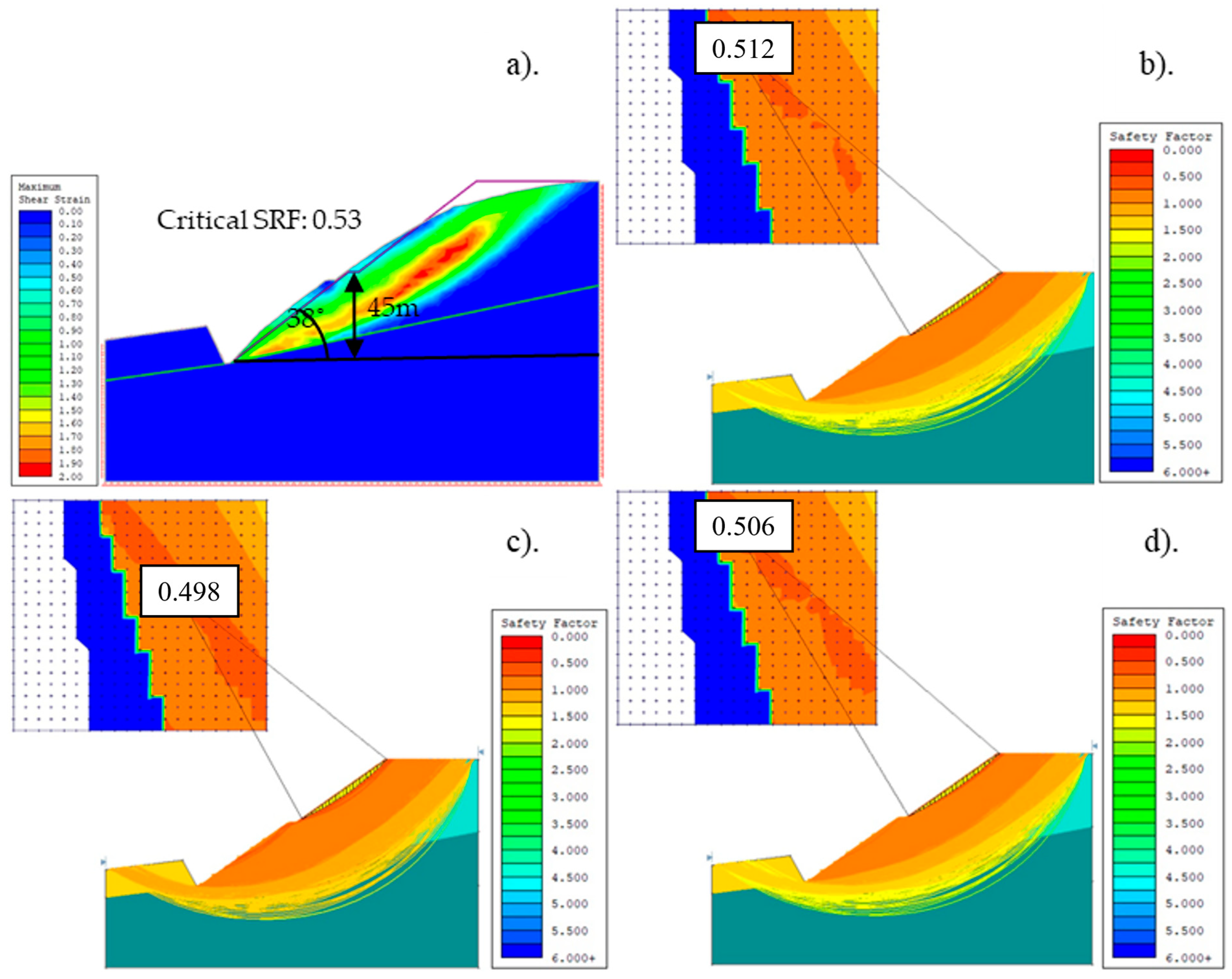
The peak of the 45 m internal waste dump (Figure 4) was close to that of the 40 m internal waste dump. The shear strength of the toe area increased and the FEM SRF = 0.65, the Bishop method SRF = 0.587, the Janbu simplified method SRF = 0.576, and the Spencer simplified method SRF = 0.581. Therefore, the internal dump does not meet the stability requirements.

3.1.2. The Impact of Differences in the Dip Angle of the Dump

A failed dump slope with an initial height of 35 m and a 38° slope angle was simulated using the determined strength parameters. The average height of the “Baganuur” coal mine internal waste dump is 35 m. Therefore, the purpose of this numerical model was to determine the influence of an appropriate difference in dump dip parameters at a dip angle of 5°. The FEM and LEM were used to test dip angles between 28° and 48°.
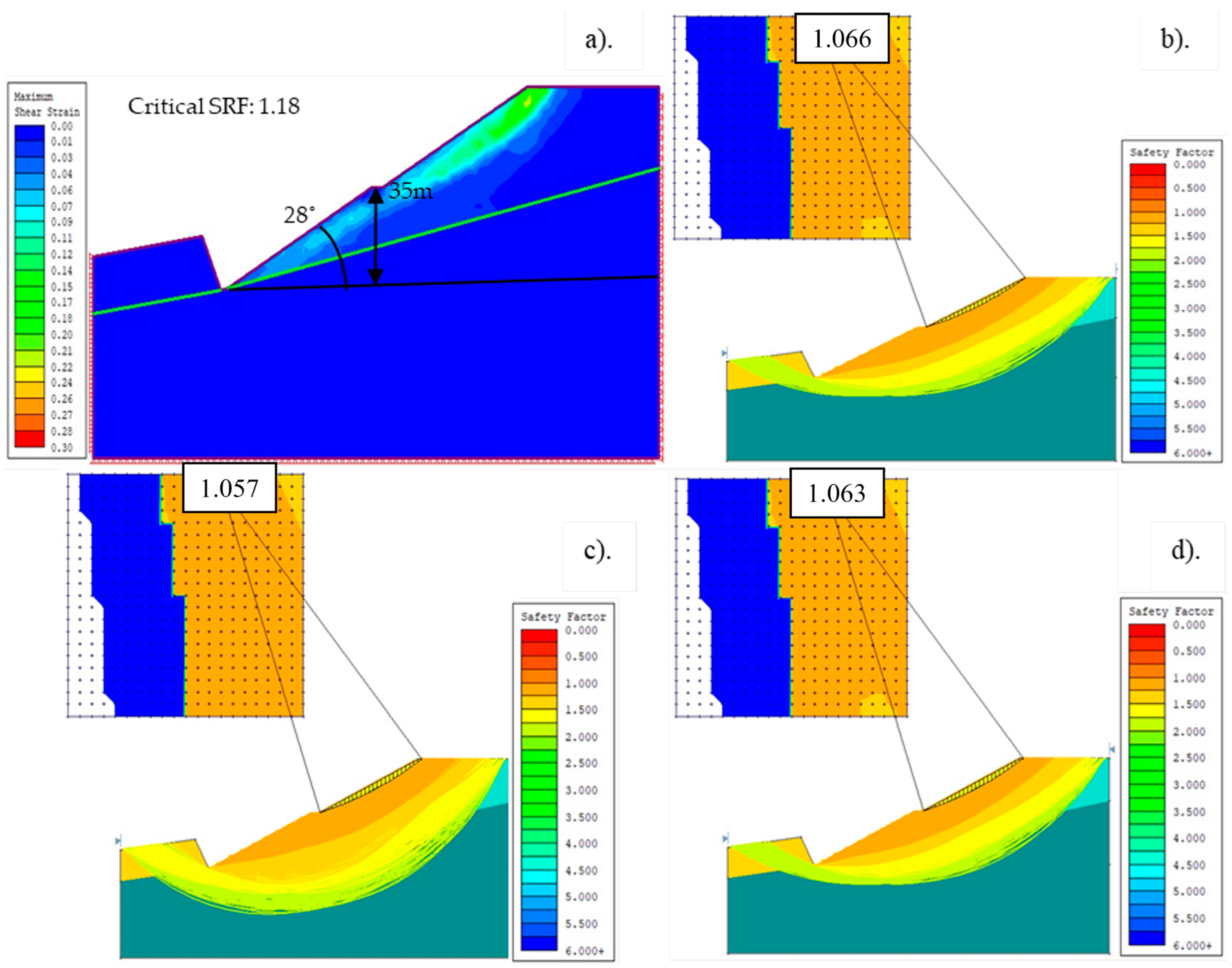
At a dump dip angle of 28° and height of 35 m (Figure 5), there was a slight displacement at the top of the internal dump and no strong shear strength at the peak area. The numerical model results all show SRF values over 1, i.e., the FEM SRF = 1.18, the Bishop method SRF = 1.066, the Janbu simplified method SRF = 1.057, and the Spencer simplified method SRF = 1.063. This means that this dip angle is safe in terms of slope stability.
At a dump dip angle of 33° and height of 35 m, there is slight displacement at the top of the internal dump and strong maximum shear strength at the peak area. The FEM SRF = 0.96, the Bishop method SRF = 0.88, the Janbu simplified method SRF = 0.871, and the Spencer simplified method SRF = 0.877; these are all close to SRF 1. However, this does not mean that this is a safe dump dip angle.
When a displacement of 43° is simulated, the FEM SRF = 0.62, the Bishop method SRF = 0.549, the Janbu simplified method SRF = 0.538, and the Spencer simplified method SRF = 0.543; these are all below the critical SRF value of 1 at a height of 35 m.
In the last numerical model, simulating a 48° dump dip and 35 m height, there is too much displacement at the top of the dump to toe area and strong maximum shear strength at the peak area. The results of the numerical model show that the FEM SRF = 0.50, the Bishop method SRF = 0.438, the Janbu simplified method SRF = 0.427, and the Spencer simplified method SRF = 0.434. These results are far from the SRF value of 1 and show that the waste dump will continue to slide down. Table 4 shows the measure of the internal waste dump dip angle with 5° differences.

3.1.3. Design of the Internal Dump

The design of the internal dump should be safe and economical. The primary aim of creating an internal dump is to provide effective and stable working conditions for mining and to facilitate proper handling of the overburden. The design of an overburden dump prevents accidents and is environmentally friendly.
Maintaining the stability of an internal dump slope has several benefits. It has a significant impact on the future stability of the mine, the safety of the equipment, the safety of the workers, and the economy. Therefore, it is important to determine and test the correct parameters based on the physio-mechanical data of the “Baganuur” lignite coal mine internal rock dump due to the instability and landslides occurring in this mine.
In the “Baganuur” open cast coal mine, the average computed waste dump dip angle is 38°. Based on the numerical data provided earlier, the critical SRF was under 1 and the impacts of displacement and shear stress were considered. However, in this numerical model, we considered the impact of changes in dump height with the safe angle of 28° obtained through the numerical models. The dump heights that had the strongest influence on the slope stability at the internal dip angle were selected for subsequent numerical models. Studying the effects of changes in dump height by using the computed dip angle of the current waste dump is of practical and theoretical importance. This section was tested with a dump dip angle of 28° and by changing the dump height by 5 m between 30 m and 50 m.
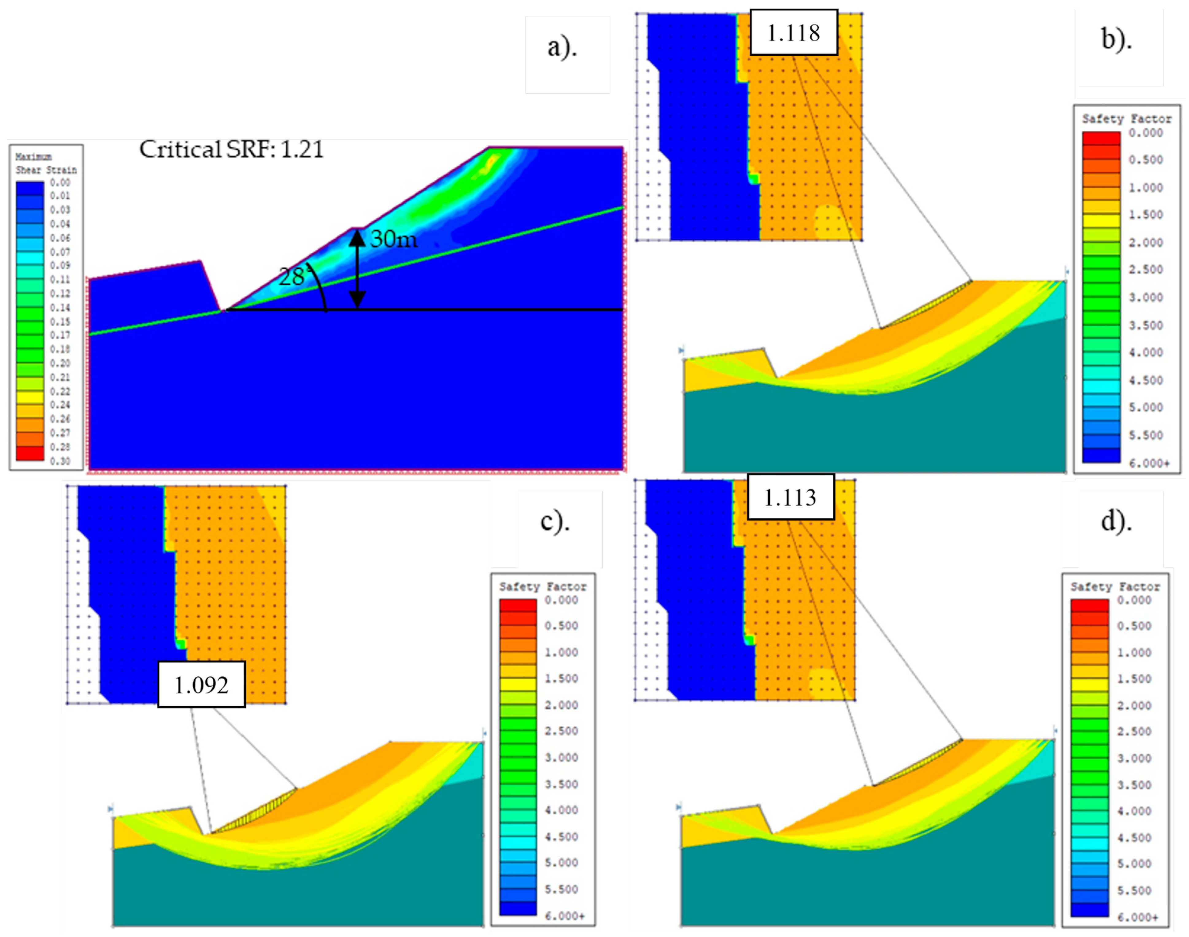
Figure 6 shows a deformation vector in the direction of the slide obtained after using the slide situation tool in the Rocscience Phase2 software. The simulation considered a height of 35 m and a dip of 26°. The face of the internal dump exhibited a slight displacement. The critical SRFs obtained show that the slope is stable: the FEM SRF = 1.21, the Bishop method SRF = 1.118, the Janbu simplified method SRF = 1.092, and the Spencer simplified method SRF = 1.113.
The dump height was increased by 10 m to 40 m in the numerical models. The reason for this is that we already tested the dump parameters of 28° dip angle and 35 m dump height in a previous numerical model. The displacement from the peak of the internal dump and the peak shear stress slightly increased. The simulation results were as follows: the critical FEM SRF = 1.13, the Bishop method SRF = 1.062, the Janbu simplified method SRF = 1.052, and the Spencer simplified method SRF = 1.059. This means that it is possible to increase both the safety and capacity of the dump. The results from the four different methods show that the waste dump is stable at a height of 40 m and dip angle of 28°.
When the dump height increased by another 5 m to 45 m, the peak shear stress increased. In addition, the displacement increased from the peak to the toe. The critical FEM SRF = 1.09, the Bishop method SRF = 0.975, the Janbu simplified method SRF = 0.963, and the Spencer simplified method SRF = 0.969. Here, the slope stability decreased, and the result of the Bishop method is over SRF 1, but the other three methods, Bishop, Janbu, and Spencer, are under SRF 1. The results of these last three methods show that the internal dumps would slide.
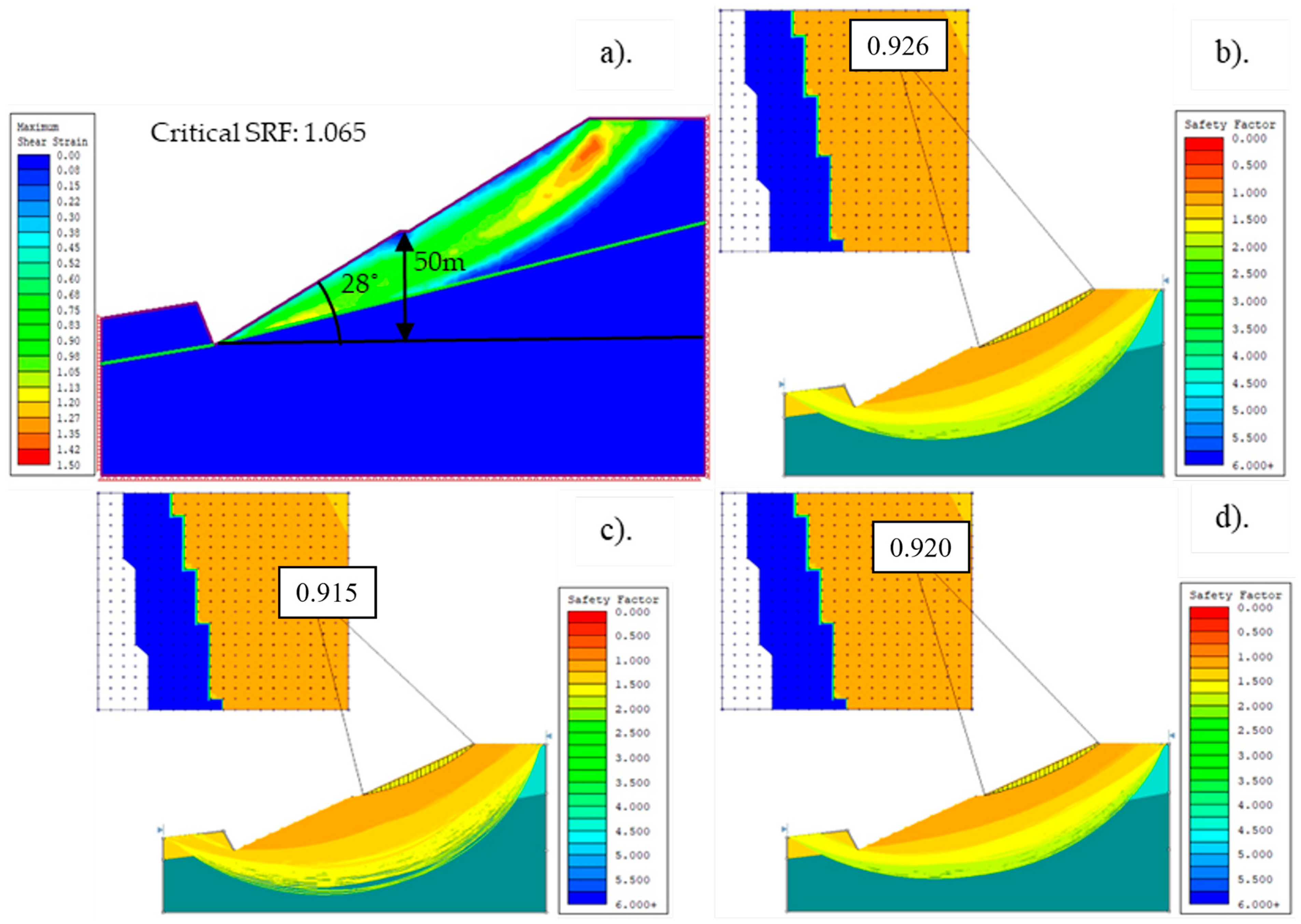
At a height of 50 m (Figure 7), the maximum shear stress reached the peak area, and the same displacement increased from the peak, at the center area, and at the toe. The results were similar to those of the previous numerical model, where the dump height was 45 m. The FEM SRF = 1.065, the Bishop method SRF = 0.926, the Janbu simplified method SRF = 0.915, and the Spencer simplified method SRF = 0.920. Slope stability decreased, and the Bishop method obtained an SRF value over 1, but the other three methods, Bishop, Janbu, and Spencer, all obtained SRF values under 1. The results of the last three methods show that it is possible that the internal dump will slide.
The numerical simulation results showed a slight shear stress in the toe area. According to the FEM results, the internal dip is stable when the dump height is 50 m. However, based on the Bishop, Janbu, and Spencer methods, dump heights over 45 m and 50 m are unstable.
The factor of safety (FS) for each numerical method, with a dump angle of 28° (DA28°) and a 5 m increment in dump height from DH 30 m to DH 50 m, is summarized in Table 5.
The safety berm in an internal dump is the most important part of estimating the operational plan. In this study, the impact of safety berms of widths between 0 m (without a safety berm) and 15 m on the internal dump site was studied. In the “Baganuur” coal mine, the current average safety berm is 5 m wide.
Without a safety berm, using the internal dump parameters of 28° dip angle and 45 m height, the FEM SRF = 1.05, the Bishop method SRF = 0.941, the Janbu simplified method SRF = 0.927, and the Spencer simplified method SRF = 0.935.
With a 10 m safety berm, when the internal dump parameters were 28° dip angle and 45 m height, the FEM SRF = 1.12, the Bishop method SRF = 1.038, the Janbu simplified method SRF = 1.025, and the Spencer simplified method SRF = 1.031. The numerical model results show an SRF value greater than 1, showing that this is safe.
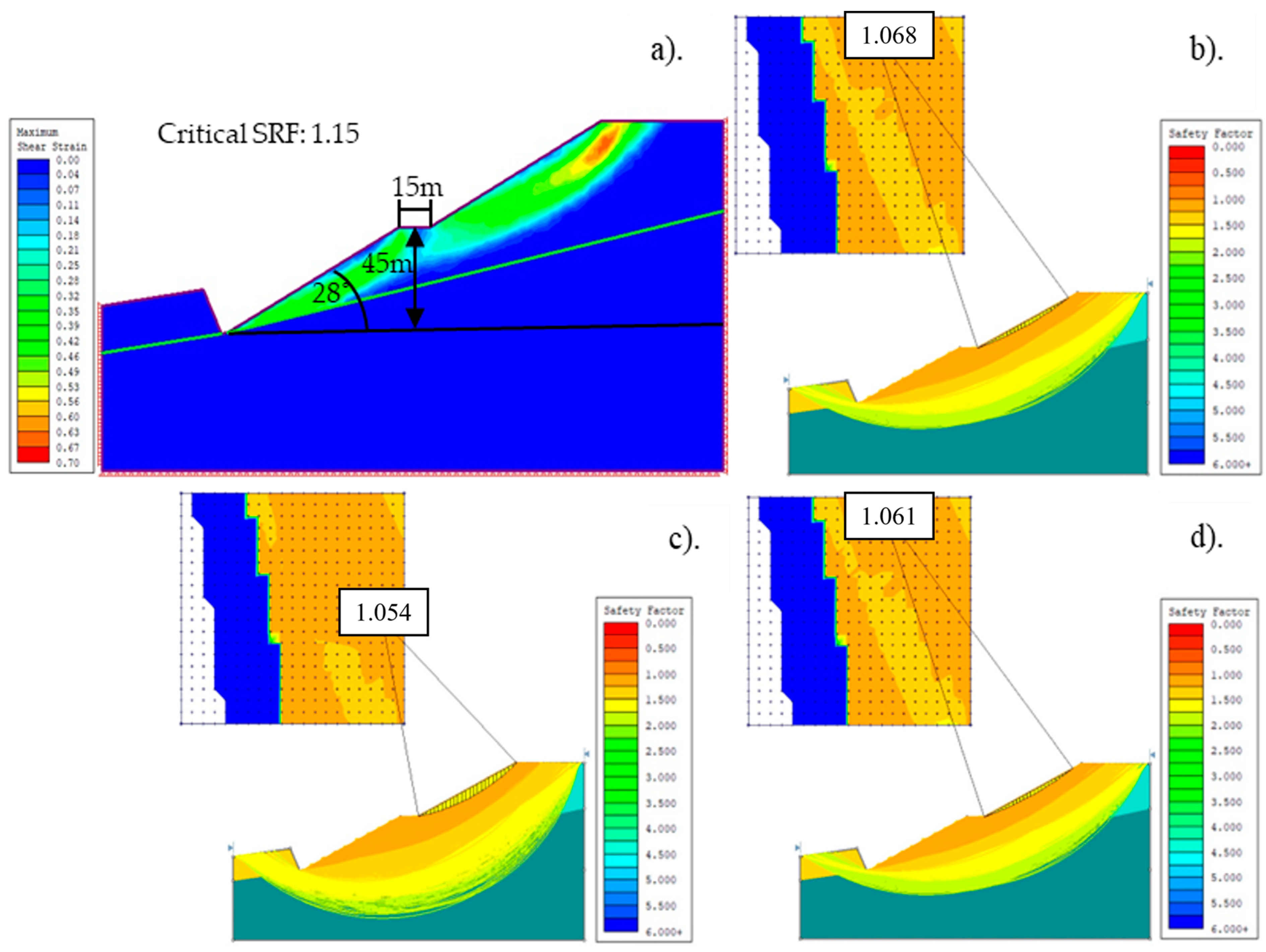
Figure 8 shows that using a 15 m safety berm improves the capacity and stability of the internal dump. The FEM SRF = 1.15, the Bishop method SRF = 1.068, the Janbu simplified method SRF = 1.054, and the Spencer simplified method SRF = 1.061. The numerical model results all show an SRF value over 1, showing that this is safe.
The factor of safety (FS) for each numerical method, with a dump angle of 28° (DA28°), a dump height of 45 m, and a safety berm width from 0 m to 15 m, is summarized in Table 6.
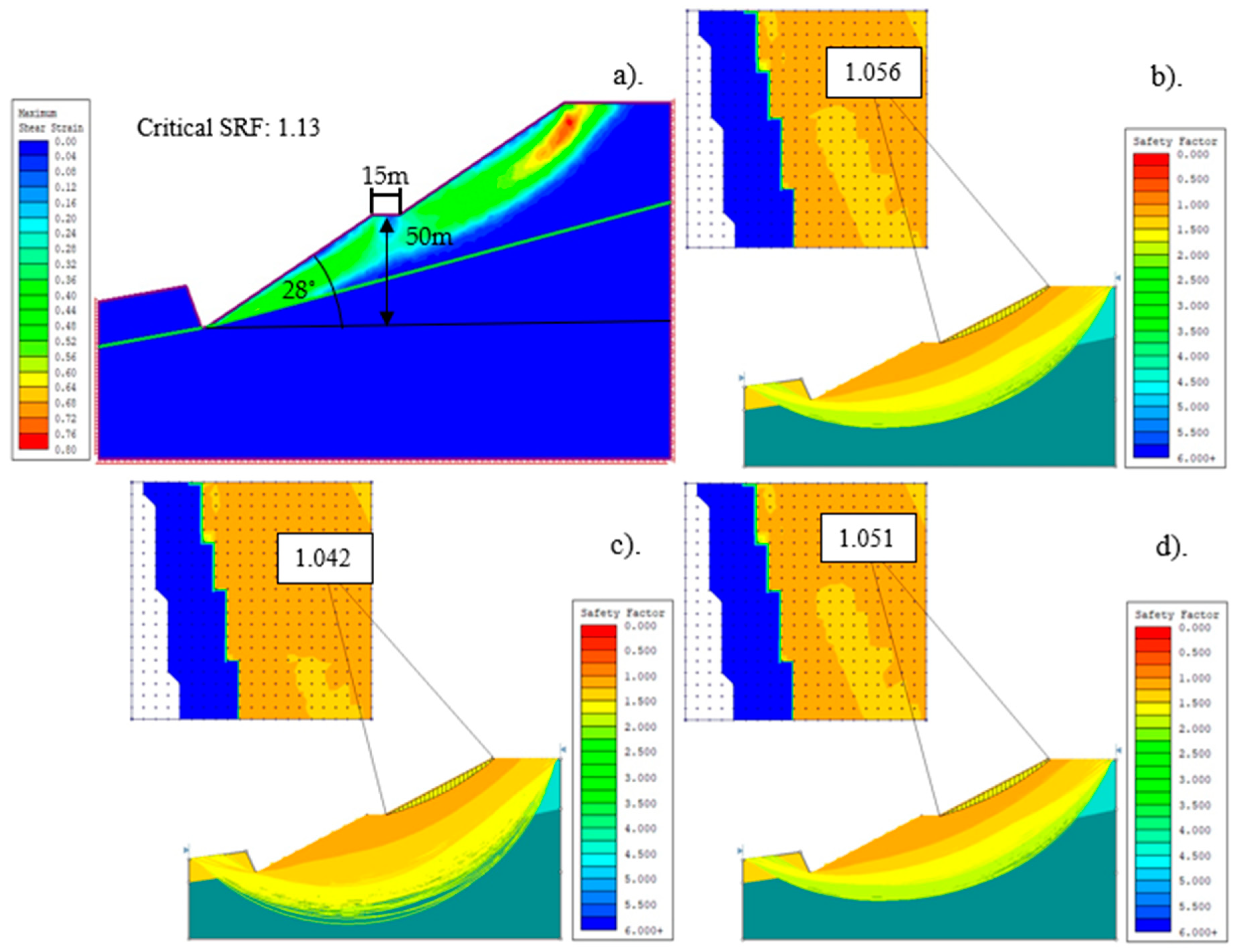
Without a safety berm, with the internal dump parameters of 28° dip angle and 45 m height, the FEM SRF = 1.03, the Bishop method SRF = 0.958, the Janbu simplified method SRF = 0.945, and the Spencer simplified method SRF = 0.952. The peak of the internal dump shear stress increased. However, the results of the FEM showed that it was still stable.
When a 10 m width safety berm was simulated with the internal dump parameters of 28° dip angle and 45 m height, the FEM SRF = 1.09, the Bishop method SRF = 0.984, the Janbu simplified method SRF = 0.973, and the Spencer simplified method SRF = 0.980. The results are similar to those obtained without a safety berm at a height of 50 m.
The last numerical model results show that the SRF value of the four different methods is over 1, which means that it is possible to stabilize and increase the parameters of the internal dump. The results (Figure 9) were as follows: FEM SRF = 1.13, Bishop method SRF = 1.056, Janbu simplified method SRF = 1.042, and Spencer simplified method SRF = 1.051.
The factor of safety (FS) for each numerical method with a dump angle of 28° (DA28°), a dump height of 50 m, and a safety berm from 0 m to 15 m is summarized in Table 7.

4. Conclusions

This study utilized the physical–mechanical data of the internal dump and relevant parameters to evaluate slope stability in an open-pit coal mine. The numerical model test considered the current parameters of the mining site as well as other relevant factors. The previously mentioned variables included the height of the internal dump, the angle of the dump dip, and the safety berm established for safety purposes. The maximum shear stress resulting from the displacement of the internal dump as a result of mining was determined through numerical modeling and testing using the 2D software Rocscience Phase2 and Slide v6 for comparison.
Changes in the important parameters of the internal dump using the FEM and the LEM are shown using numerical simulation models. The results were compared with the SRF values. Based on this, the most influential parameters were the dump height and the dump dip angle. Four to five different parameters were tested by increasing and decreasing the internal dump height (30 m; 35 m—initial; 40 m; and 45 m) and dip angle (28°; 33°; 38°—initial; 43°; and 48°). Based on the numerical models, changes in dip angle had a greater impact than changes in height.
This study also found that the results generated by the above laboratory tests can increase the capacity by up to 56% compared to the current parameters of the mine. We find that when we increase the safety berm to 15 m at an angle of 28 degrees, the internal dump capacity increases by 56%. Hence, we can conclude that all the results from the four models show that the internal dump is stable and safe. The results are as follows: FEM method = 1.13, Bishop method = 1.056, Janbu simplified method = 1.042, and Spencer simplified method = 1.051. We can generalize these results to state that the internal dump is safe and stable and that it enhances mining production.
The LEM/FEM numerical simulations provide a deeper understanding of the dump slope and suggest that there may be adequate space to handle more dump material while maintaining a greater level of safety. Even though the collapse, sliding, and circumstances of internal piles in open-pit coal mines are handled differently by the FEM and LEM techniques, according to the overall research results many aspects may be changed in practice. This study will impact future research on internal dump slope stability to guarantee that mining operations are sustainable.

Author Contributions

Conceptualization, B.E.; methodology, B.E.; software, B.E.; validation, B.E.; formal analysis, B.E.; investigation, B.E.; resources, H.I. and T.A.; data curation, B.E. and H.I.; writing—original draft preparation, B.E.; writing—review and editing, B.E.; visualization, T.A.; supervision, H.T. and T.A.; project administration, T.A.; funding acquisition, T.A. and H.I. All authors have read and agreed to the published version of the manuscript.

Funding

This research received no external funding.

Data Availability Statement

The data presented in this study are available on request from the corresponding author. The data are not publicly available due to the privacy of the patients who assisted in the research.

Acknowledgments

We thank the anonymous reviewers and members of the editorial team for their comments and contributions.

Conflicts of Interest

The authors declare no conflict of interest.

Abbreviations

FEMFinite element method
LEMLimit equilibrium method
SRFStrength reduction factor
FSFactor of safety
FDMFinite difference method
DSRDouble strength reduction
SSRShear strength reduction
IWDInternal waste dump
DHDump height
DADump angle

References

  1. Park, J.; Kwon, E.; Chung, E.; Kim, H.; Battogtokh, B.; Woo, N.C. Environmental Sustainability of Open-Pit Coal Mining Practices at Baganuur, Mongolia. Sustainability 2019, 12, 248. [Google Scholar] [CrossRef]
  2. Rouainia, M.; Davies, O.; O’Brien, T.; Glendinning, S. Numerical Modelling of Climate Effects on Slope Stability. Proc. Inst. Civil. Eng.-Eng. Sustain. 2009, 162, 81–89. [Google Scholar] [CrossRef]
  3. Kaithola, A.; Verma, D.; Gupte, S.S.; Singh, N.T. A Coal Mine Dump Stability Analysis—A Case Study. Geomaterial 2011, 1, 1–13. [Google Scholar] [CrossRef]
  4. Göktepe, F.; Keskin, I. A Comparison Study between Traditional and Finite Element Methods for Slope Stability Evaluations. J. Geol. Soc. India 2018, 91, 373–379. [Google Scholar] [CrossRef]
  5. Liu, S.Y.; Shao, L.T.; Li, H.J. Slope Stability Analysis Using the Limit Equilibrium Method and Two Finite Element Methods. Comput. Geotech. 2015, 63, 291–298. [Google Scholar] [CrossRef]
  6. Nguyen, P.M.V.; Wrana, A.; Rajwa, S.; Różański, Z.; Frączek, R. Slope Stability Numerical Analysis and Landslide Prevention of Coal Mine Waste Dump under the Impact of Rainfall—A Case Study of Janina Mine, Poland. Energies 2022, 15, 8311. [Google Scholar] [CrossRef]
  7. Onyango, J.; Zhang, C. Numerical Analysis of Slope Stability by Strength Reduction in Finite Elements Using ANSYS a Case Study of Qinglong-Xingyi Expressway Contract Section T1(K11+790~K11+875). Environ. Earth Sci. Res. J. 2019, 6, 89–96. [Google Scholar] [CrossRef]
  8. Guo, T.; Zhou, W.; Li, Z.; Zhang, C.; Cai, Q.; Tian, Y.; Qin, H.; Liu, F.; Jiskani, I.M.; Zhang, D. Optimization of Land Saving and Loss Reducing and Slope Stability Variation Patterns in Open-Pit Mine. Geofluids 2021, 2021, 6620235. [Google Scholar] [CrossRef]
  9. Fredlund, D. Computer Software for Slope Stability Analysis. 1976. Available online: https://www.researchgate.net/publication/347986725_Computer_software_for_slope_stability_analysis (accessed on 28 April 2023).
  10. Manouchehrian, A.; Gholamnejad, J.; Sharifzadeh, M. Development of a Model for Analysis of Slope Stability for Circular Mode Failure Using Genetic Algorithm. Environ. Earth Sci. 2014, 71, 1267–1277. [Google Scholar] [CrossRef]
  11. Cai, F.; Ugai, K. Discussion: Slope Stability Analysis by Finite Elements. Géotechnique 2001, 51, 653–654. [Google Scholar] [CrossRef]
  12. Beyabanaki, S.A.R. A Comparison between Using Finite Difference and Limit Equilibrium Methods for Landslide Analysis of Slopes Containing a Weak Layer. Am. J. Eng. Res. 2020, 9, 68–79. [Google Scholar]
  13. Gupte, S. Optimisation of Internal Dump Capacity and Stability Analysis in a Coal Mine—A Case Study. In Proceedings of the First Asia Pacific Slope Stability in Mining Conference, Brisbane, Australia, 6–8 September 2016; Australian Centre for Geomechanics: Perth, Australia, 2016; pp. 557–570. [Google Scholar]
  14. Deng, D.; Li, L.; Zhao, L. Limit Equilibrium Method (LEM) of Slope Stability and Calculation of Comprehensive Factor of Safety with Double Strength-Reduction Technique. J. Mt. Sci. 2017, 14, 2311–2324. [Google Scholar] [CrossRef]
  15. Phase2-2D Finite Element Program for Calculating Stresses and Estimating Support around Underground Excavations. 2001. Available online: https://www.rocscience.com/downloads/phase2/Phase2_ModelReference.pdf (accessed on 28 April 2023).
  16. Slide2-Documentation. Available online: https://www.rocscience.com/help/slide2/documentation (accessed on 28 April 2023).
  17. GeoStudio Reference Manuals—GeoStudio Support. Available online: https://www.geoslope.support/kb/article/10-geostudio-reference-manuals/ (accessed on 30 April 2023).
  18. GeoWizard—Free Programs for Geoengineers. Available online: http://www.geowizard.org/doc_hyrcan_tutorials.html (accessed on 28 April 2023).
  19. PLAXIS 2D—Reference Manual. Available online: https://communities.bentley.com/cfs-file/__key/communityserver-wikis-components-files/00-00-00-05-58/3113.PLAXIS2DCE_2D00_V20.02_2D00_2_2D00_Reference.pdf (accessed on 5 May 2020).
  20. Geoslope—Slope Stability Verification Manual. Available online: https://downloads.geoslope.com/geostudioresources/books/11/4/Slope%20Stability%20Verification%20Manual.pdf (accessed on 28 April 2023).
  21. Verma, D.; Kainthola, A.; Gupte, S.S.; Singh, T.N. A Finite Element Approach of Stability Analysis of Internal Dump Slope in Wardha Valley Coal Field, India, Maharashtra. Am. J. Min. Metall. 2013, 1, 1–6. [Google Scholar]
  22. Pan, W.; Pan, W.; Luo, J.; Fan, L.; Li, S.; Erdenebileg, U. Slope Stability of Increasing Height and Expanding Capacity of South Dumping Site of Hesgoula Coal Mine: A Case Study. Int. J. Coal Sci. Technol. 2021, 8, 427–440. [Google Scholar] [CrossRef]
  23. Behera, P.K.; Sarkar, K.; Singh, A.K.; Verma, A.K.; Singh, T.N. Dump Slope Stability Analysis—A Case Study. J. Geol. Soc. India 2016, 88, 725–735. [Google Scholar] [CrossRef]
  24. Jana, A.; Dey, A. Stability Analysis of Rock Slope Using Combined Continuum Interface Element Method. In Proceedings of the Indian Geotechnical Conference, Guwahati, India, 14–16 December 2017. [Google Scholar]
  25. Carranza-Torres, C.; Zhao, J. Analytical and Numerical Study of the Effect of Water Pressure on the Mechanical Response of Cylindrical Lined Tunnels in Elastic and Elasto-Plastic Porous Media. Int. J. Rock. Mech. Min. Sci. 2009, 46, 531–547. [Google Scholar] [CrossRef]
  26. Pal, S.; Kaynia, A.; Bhasin, R.; Paul, D. Earthquake Stability Analysis of Rock Slopes: A Case Study. Rock. Mech. Rock. Eng. 2012, 45, 205–215. [Google Scholar] [CrossRef]
  27. Ulusay, R.; Aksoy, H. Assessment of the Failure Mechanism of a Highwall Slope under Spoil Pile Loadings at a Coal Mine. Eng. Geol. 1994, 38, 117–134. [Google Scholar] [CrossRef]
  28. Richards, P.G.; Torr, D.G.; Torr, M.R. Photodissociation of N 2: A Significant Source of Thermospheric Atomic Nitrogen. J. Geophys. Res. 1981, 86, 1495. [Google Scholar] [CrossRef]
  29. Singh, R.P.; Dubey, C.S.; Singh, S.K.; Shukla, D.P.; Mishra, B.K.; Tajbakhsh, M.; Ningthoujam, P.S.; Sharma, M.; Singh, N. A New Slope Mass Rating in Mountainous Terrain, Jammu and Kashmir Himalayas: Application of Geophysical Technique in Slope Stability Studies. Landslides 2013, 10, 255–265. [Google Scholar] [CrossRef]
  30. Bishop 1955 Method of Slices|PDF. Available online: https://www.scribd.com/doc/88203869/Bishop-1955-Method-of-Slices (accessed on 29 April 2023).
  31. Slope Stability Computations (Janbu, 1973)|PDF. Available online: https://www.scribd.com/doc/311344815/Slope-Stability-Computations-Janbu-1973 (accessed on 29 April 2023).
  32. Jing, L. A Review of Techniques, Advances and Outstanding Issues in Numerical Modelling for Rock Mechanics and Rock Engineering. Int. J. Rock. Mech. Min. Sci. 2003, 40, 283–353. [Google Scholar] [CrossRef]
  33. Zienkiewicz, O.C.; Cheung, Y.K. The Finite Element Method in Structural and Continuum Mechanics: Numerical Solution of Problems in Structural and Continuum Mechanics; McGraw-Hill: New York, NY, USA, 1970. [Google Scholar]
  34. Duncan, J.M. State of the Art: Limit Equilibrium and Finite-Element Analysis of Slopes. J. Geotech. Eng. 1996, 122, 577–596. [Google Scholar] [CrossRef]
  35. Igwe, O.; Chukwu, C. Slope Stability Analysis of Mine Waste Dumps at a Mine Site in Southeastern Nigeria. Bull. Eng. Geol. Environ. 2019, 78, 2503–2517. [Google Scholar] [CrossRef]
  36. Wang, Z.; Liu, B.; Han, Y.; Wang, J.; Yao, B.; Zhang, P. Stability of Inner Dump Slope and Analytical Solution Based on Circular Failure: Illustrated with a Case Study. Comput. Geotech. 2020, 117, 103241. [Google Scholar] [CrossRef]
  37. Wahyudi, S.; Shimada, H.; Sasaoka, T.; Hamanaka, A.; Amarsaikhan, T.; Mao, P.; Dintwe, T.K.M.; Moses, D. Study of Internal Waste Dump-Induced Shear Stress Behavior on Pit-Slope. J. Geosci. Environ. Prot. 2020, 8, 71–86. [Google Scholar] [CrossRef]
Figure 1. Flow chart of the overall study of slope stability using numerical simulation methods.
Mining 03 00041 g001
Figure 2. Numerical simulation of internal dump ((a). current situation of area under study, (b). main numerical simulation, (c). main model parameters on AutoCAD design). Here, θ = deposit angle, α = internal dump dip angle, H = bench height, d = berm width, β = floor angle, H2 = overall bench height.
Mining 03 00041 g002
Figure 3. Mohr–Coulomb failure criterion.
Mining 03 00041 g003
Figure 4. Slope design with a height of 45 m at 38° and safety berm width of 5 m (a). FEM method = 0.53, (b). Bishop method=0.512, (c). Janbu simplified method = 0.498, (d). Spencer simplified method = 0.506).
Mining 03 00041 g004
Figure 5. Slope design with a height of 35 m, dip angle of 28°, and safety berm width 5 m (a). FEM method = 1.18, (b). Bishop method = 1.066, (c). Janbu simplified method = 1.057, (d). Spencer simplified method = 1.063).
Mining 03 00041 g005
Figure 6. Slope design with a height of 30 m, a dip angle of 28°, and a safety berm width of 5 m (a). FEM method = 1.21, (b). Bishop method = 1.118, (c). Janbu simplified method = 1.092, (d). Spencer simplified method = 1.113).
Mining 03 00041 g006
Figure 7. Slope design with height of 50 m, dip angle of 28°, and safety berm width of 5 m (a). FEM method = 1.065, (b). Bishop method = 0.926, (c). Janbu simplified method = 0.915, (d). Spencer simplified method = 0.920).
Mining 03 00041 g007
Figure 8. Slope design with a height of 45 m, dip angle of 28°, and safety berm width of 5 m (a). FEM method = 1.15, (b). Bishop method = 1.068, (c). Janbu simplified method = 1.054, (d). Spencer simplified method = 1.061).
Mining 03 00041 g008
Figure 9. Slope design with height of 50 m, dip angle of 28°, and safety berm width of 5 m (a). FEM method = 1.13, (b). Bishop method = 1.056, (c). Janbu simplified method = 1.042, (d). Spencer simplified method = 1.051).
Mining 03 00041 g009
Table 1. The numerical simulation model parameters.
Dip of internal waste dump ( α )between 25 ° and 50 °
Height of internal waste dump (H)between 30 m and 50 m
Safety berm of internal waste dump (d)between 0 m and 15 m
Floor rock ( β )12 °
Dip of coal seam ( θ )65 °
Thickness of coal seam20 m
Table 2. The rock mechanical strength properties of the internal dump materials.
MaterialUnit Weight (MN/m3)Friction Angle (Degree)Tensile Strength (MPa)Cohesion (MPa)Young’s Module (MPa)Poisson’s Ratio
Internal Waste Dump0.02280024.750.35
Coal0.0131.83.940.225500.42
Floor Rock0.0228.34.50.431300.41
Table 3. The internal waste dump with 5 m differences in height.
Dump Height with 5 m DifferencesFS
FEMSimplified Bishop MethodJanbu Simplified MethodSpencer Simplified Method
DA38° DH30 m0.860.7490.7370.745
DA38° DH35 m0.770.6530.6400.648
DA38° DH40 m0.650.5870.5760.581
DA38° DH45 m0.530.5120.4980.506
Here, FEM = finite element method; FS = factor of safety; DA = dump angle; DH = dump height.
Table 4. The internal waste dump with 5° differences in dip angle.
Dump Dip Angle 5° DifferencesFS
FEMSimplified Bishop MethodJanbu Simplified MethodSpencer Simplified Method
DA28° DH35 m1.181.0661.0571.063
DA33° DH35 m0.960.8800.8710.877
DA43° DH35 m0.620.5490.5380.543
DA48° DH35 m0.500.4380.4270.434
Here, FEM = finite element method, FS = factor of safety, DA = dump angle, DH = dump height.
Table 5. The internal waste dump with 5 m differences in height.
Dump Height 5 m DifferencesFS
FEMSimplified Bishop MethodJanbu Simplified MethodSpencer Simplified Method
DA28° DH30 m1.211.1181.0921.113
DA28° DH40 m1.131.0621.0521.059
DA28° DH45 m1.090.9750.9630.969
DA28° DH50 m1.0650.9260.9150.920
Here, FEM = finite element method, FS = factor of safety, DA = dump angle, DH = dump height.
Table 6. The internal waste dump safety berm with 5 m differences in width.
DA28° DH45 mFS
FEMSimplified Bishop MethodJanbu Simplified MethodSpencer Simplified Method
Safety berm 0 m1.050.9410.9270.935
Safety berm 10 m1.121.0381.0251.031
Safety berm 15 m1.151.0681.0561.061
Table 7. The internal waste dump safety berm with 5 m differences in width.
DA28° DH50 mFS
FEMSimplified Bishop MethodJanbu Simplified MethodSpencer Simplified Method
Safety berm 0 m1.030.9580.9450.952
Safety berm 10 m1.090.9840.9730.980
Safety berm 15 m1.131.0561.0421.051
Here, FEM = finite element method, FS = factor of safety, DA = dump angle, DH = dump height.
Disclaimer/Publisher’s Note: The statements, opinions and data contained in all publications are solely those of the individual author(s) and contributor(s) and not of MDPI and/or the editor(s). MDPI and/or the editor(s) disclaim responsibility for any injury to people or property resulting from any ideas, methods, instructions or products referred to in the content.

