Review

Recent Advances in Electrospun Fibers for Biological Applications

by
Bénédicte Fromager
1,*,
Emilie Marhuenda
2,
Benjamin Louis
1,
Norbert Bakalara
3,
Julien Cambedouzou
1,* and
David Cornu
1
1
Institut Européen des Membranes (IEM), Université de Montpellier, CNRS, ENSCM, F-34000 Montpellier, France
2
School of Engineering and Materials Science, Queen Mary University of London, London E1 4NS, UK
3
Ecole Nationale Supérieure de Technologie des Biomolécules de Bordeaux (ENSTBB), Université de Bordeaux, CNRS, Bordeaux INP, CBMN, UMR 5248, F-33615 Pessac, France
*
Authors to whom correspondence should be addressed.
Macromol 2023, 3(3), 569-613; https://doi.org/10.3390/macromol3030033
Submission received: 6 June 2023 / Revised: 5 July 2023 / Accepted: 31 July 2023 / Published: 16 August 2023
(This article belongs to the Special Issue Functional Polymer-Based Materials)

Abstract

:
Electrospinning is a simple and versatile method to generate nanofibers. Remarkable progress has been made in the development of the electrospinning process. The production of nanofibers is affected by many parameters, which influence the final material properties. Electrospun fibers have a wide range of applications, such as energy storage devices and biomedical scaffolds. Among polymers chosen for biological scaffolds, such as PLA or collagen, polyacrylonitrile (PAN) has received increasing interest in recent years due to its excellent characteristics, such as spinnability, biocompatibility, and commercial viability, opening the way to new applications in the biotechnological field. This paper provides an overview of the electrospinning process of a large range of polymers of interest for biomedical applications, including PLA and PEO. It covers the main parameters and operation modes that affect nanofiber fabrication. Their biological applications are reviewed. A focus is placed on PAN fiber formation, functionalization, and application as scaffolds to allow cell growth. Overall, nanofiber scaffolds appear to be powerful tools in medical applications that need controlled cell culture.

1. Introduction

Fibers, in the form of continuous and elongated filaments, have been used by humans since 2700 BC with the breeding of silkworms for textile production [1]. In Australasia, silk from spiders was used for fishing, while in ancient Greece, spider webs were used as wound dressings to stop bleeding. World War II saw an increase in demand for these fibers, leading to the production of synthetic fibers derived from petroleum, sometimes with better chemical or physical properties than silk, depending on the polymer [2,3]. Nylon fibers, first introduced by DuPont, immediately caught the public’s attention. In 2018, more than 50 million tons of synthetic fibers were produced, with a predominance of polyester filaments. Therefore, many different types of synthetic polymers originating from crude oil, such as polystyrene and polyacrylonitrile (PAN), and natural biopolymers, such as chitosan and polylactic acid, have been developed one after the other for various industries. Compared to synthetic fibers, natural fibers have many advantages thanks to their abundance, availability, and low cost, explaining why the global demand for synthetic fibers has been largely reduced, with synthetic fibers having been replaced by natural biofibers [4]. Nowadays, within the domain of fiber technology, nanofiber mats have a broad range of applications, especially in areas of engineering and science. These include optical and chemical sensors, nanocatalysis, and energy storage [5,6,7], as well as applications in defense, aerospace, transportation, and protective clothing industries [6]. They are also used in air and water filters or for drug delivery for medical and biotechnological purposes [8]. To produce nanofibers, different methods have been developed, such as wet, dry, melt, and gel spinning. During these processes, polymer jets are formed under external mechanical drawing/shearing forces when passing through spinnerets, and fibers are formed due to the solidification of the jets because of drying or precipitation. However, jets are only stretched to a limited extent, corresponding to the formation of fibers with diameters ranging from 10 to 100 μm [9]. However, even with further mechanical drawing after solidification, the resulting fibers still cannot reach the nanoscale. In 1902, a novel technique similar to electrospraying was created, allowing fibers to be created at the nanoscale; this technique is known as electrospinning [10]. Both techniques rely on a high voltage to eject liquid jets, with the major difference being the viscosity and viscoelasticity of the liquid involved and, thus, the behavior of the jet [11]. Electrospinning is a simple and low-cost method to prepare fibers at the nanoscale with an electric field. This method produces non-woven nanofiber mats, where the fiber diameter ranges from ten to a hundred nanometers. Extraordinary properties, such as small diameters or large specific surface areas, can be obtained thanks to this technique. Also, a wide selection of polymers can be electrospun from diverse solvents, including aqueous solutions, making the spinning process itself environmentally friendly. Mostly toxic or corrosive solvents are used for waterproof polymers, while only some can also be electrospun from a low-toxicity solvent such as dimethyl sulfoxide (DMSO) [12,13,14]. The classic electrospinning process uses one needle to draw the polymeric solution out and form fibers. However, this method is very time-consuming, limiting the potential scale-up application of the electrospun nanofibers. Many multi-jet [15] and multi-needle [16] electrospinning methods have been investigated to overcome the productivity problem, increasing the flow rate of the solution. However, the generation of multiple jets creates other problems, such as jet repulsion and lower process controllability [17]. Polyacrylonitrile (PAN) is a synthetic polymer widely used in electrospinning due to its high tensile strength, thermal stability, carbon yield, and chemical resistivity. Electrospun PAN nanofibrous membranes have received particular interest due to their appealing properties, including small fiber diameters, as well as capabilities to control pore sizes among nanofibers and to incorporate molecules, cells, or proteins [14,18,19]. PAN is the primary precursor to prepare high-performance carbon fibers: almost 90% of the carbon nanofibers in the world are produced from PAN-based precursors [20]. Three main processes are involved in carbon fiber preparation: the spinning of PAN precursor, thermal–oxidative stabilization (ToS), and carbonization [21]. Stabilization is a complex, exothermic process and the most important step that influences the properties of the final fibers. During this step, the linear polymer transforms itself into a cyclic-structured polymer, also called a ladder-like structure. Thermal stabilization proceeds mainly at a specific temperature, ranging from 200 to 300 °C, for 1–2 h in the air [22]. Oxygen plays an important role in the physical and chemical structural changes that occur during ToS. It is recognized that oxygen not only affects the oxidative and crosslinking reactions but also makes the cyclization and dehydrogenation reactions (which occur simultaneously during the thermal stabilization process) easier. In addition, the exact reaction mechanism varies depending on the gas atmosphere, heating rate, copolymer used, etc. [23,24]. Thus, having a better understanding of the structural evolution of PAN fibers during stabilization is a major issue in predicting the final structure of the polymer and, therefore, in functionalizing it. In this study, a bibliographic review has been performed to better understand the electrospinning process, including the principle, methods, and materials. In the first part, the principle of and typical apparatus for electrospinning are discussed. Next, methods and materials are described, as well as how the compositions, structures, and properties of polymer solutions can be engineered to obtain different materials. After that, a particular focus is placed on 3D electrospun scaffolds produced for biological studies by first presenting their importance and the choice of materials, with a special focus on PAN fibers. Then, different processes that can be used to obtain relevant scaffolds are outlined. Finally, different concrete examples are highlighted. In light of their exceptional properties and the many examples reported here, scaffolds of stabilized PAN nanofibers appear to be indispensable tools for the future development of cell culture for biomedical applications.

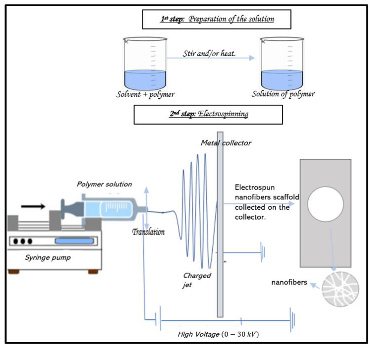
2. Electrospinning Process

2.1. Principle

The simplest form of electrospinning is the single-needle configuration, which has been investigated and reviewed by many researchers [6,9,18,25,26,27]. The simulation of the electric field and modeling of the electrospinning process were also carried out in an effort to provide a better understanding of this approach [28]. Only a few components are required: a syringe containing a polymeric solution, a metallic needle, a high-voltage power supply, and a metallic collector (with variable morphology). The power supply can be either a direct current (DC) or, more rarely, an alternating current (AC) [25]. As illustrated in Figure 1, the basic setup for electrospinning is rather simple, making it accessible to as many researchers as possible.
Free charges carried by the liquid interact with the applied electric field. Tensile-force-inducing fiber jetting occurs due to the potential difference between the charged liquid in the spinneret and the grounded collector. Usually, electrospinning unfolds in four steps (Figure 2): (i) the liquid droplet is charged, and the Taylor cone is formed; (ii) the charged jet is extended in a straight line; (iii) the jet is thinned in the presence of an electric field, and electrical bending instability appears and increases; (iv) finally, the solid jet fibers are collected by a grounded collector [17,25].

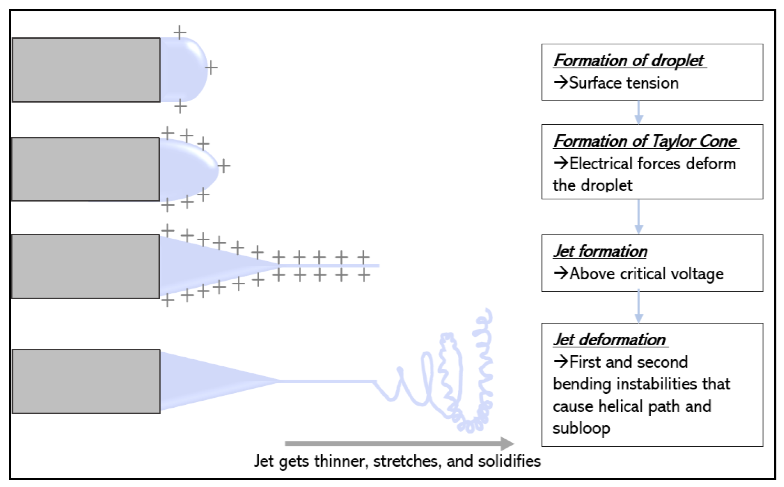
2.2. Formation of Taylor Cone upon Charging a Liquid Droplet

A syringe with a needle is commonly used as the spinneret to feed the solution at a controlled rate using a syringe pump. When there is a potential difference (ranging from 10 to 30 kV) between the spinneret and the collector, negative and positive charges will be separated within the liquid; the charges with the same polarity as the spinneret will migrate toward the droplet’s surface, leading to excess charges. By increasing the voltage, more charges will accumulate at the liquid surface. This increase in the density of surface charges tends to deform the shape of the droplet, leading to an increase in surface area to attenuate the electric repulsion [29], as illustrated in Figure 2.

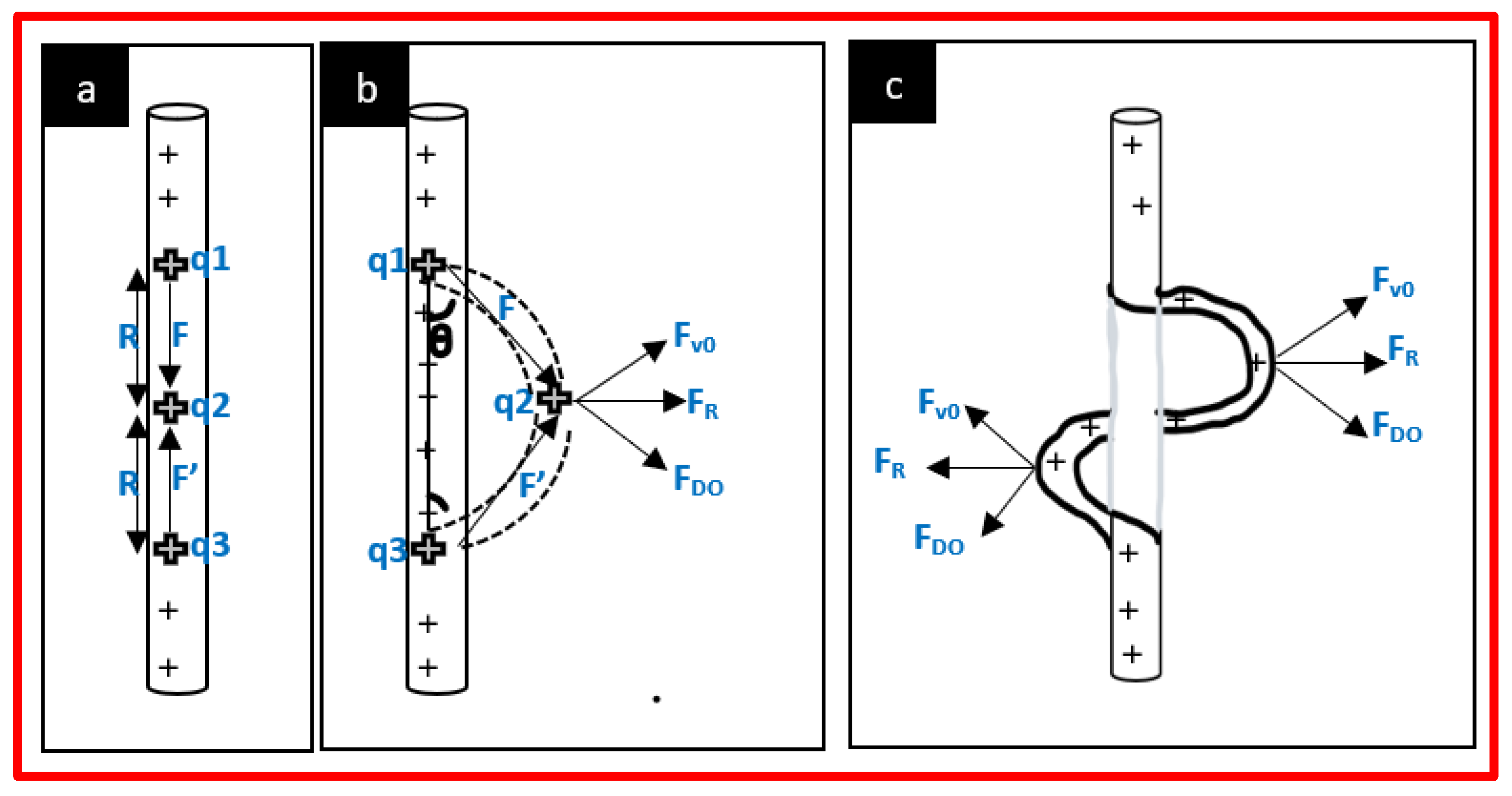
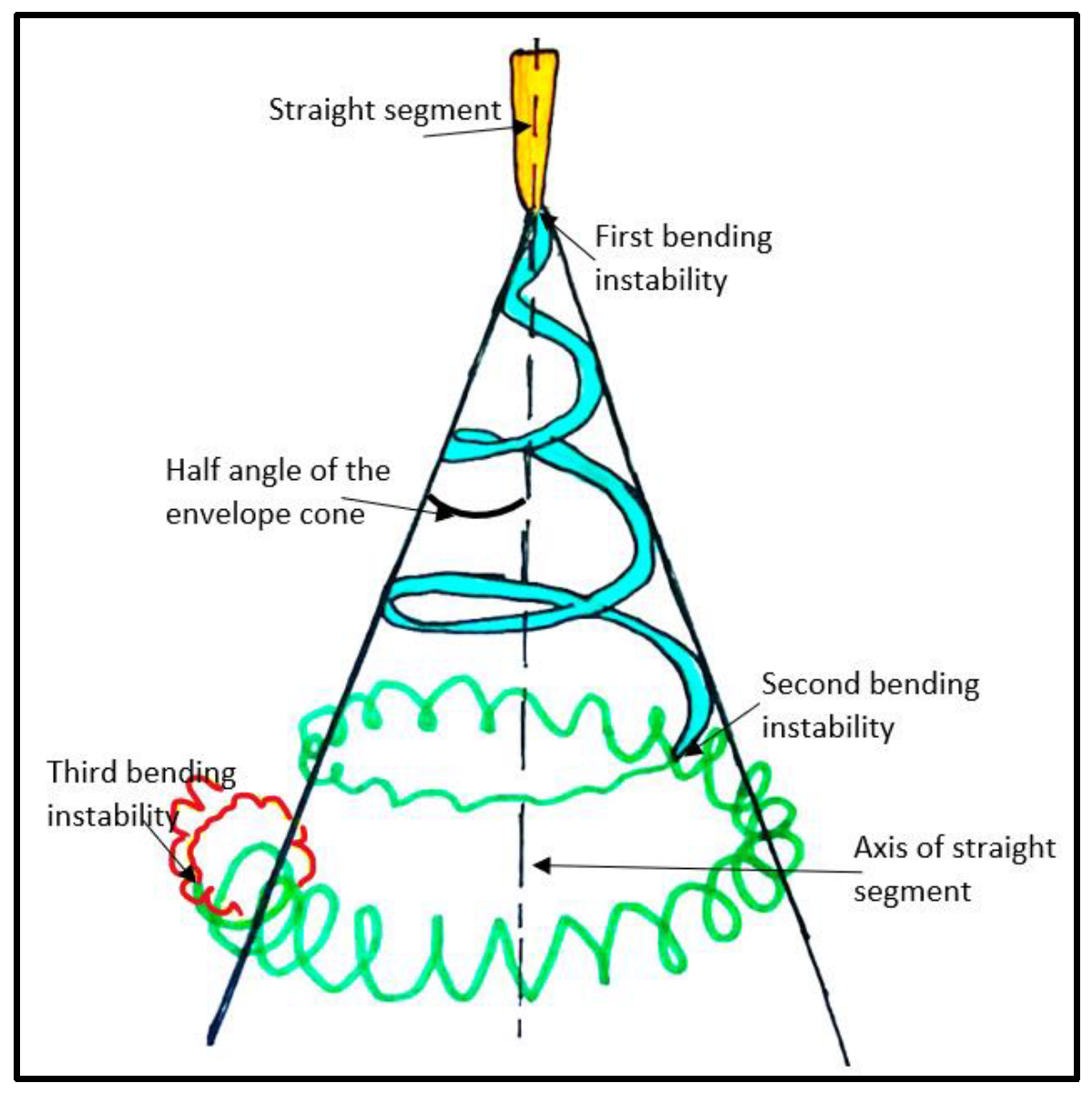
2.3. Stretching and Thinning of the Charged Jet

At the same time, the reciprocal repulsion of charges produces a force that opposes the surface tension, and ultimately, the polymer solution flows in the direction of the electric field. A further increase in the electric field causes the spherical droplet to deform and assume a conical shape, which is called the Taylor cone. At the same stage, ultrafine fibers emerge from the conical polymer droplet at high speed, accelerated by the electric field. The jet is extended in the direction of the electric field, and then it is collected by the metallic collector kept at an optimized distance [9].
The jet formed initially travels in a straight path due to surface tension and viscoelastic forces, which tend to prevent the jet from moving in other directions. Both the acceleration and the diameter of the jet decrease as the jet is continuously stretched. Solvent evaporation and a jet diameter reduction lead to an increase in the surface charge density of the fiber, which results in increasing repulsive forces in the jet. When the acceleration of the jet is too low, bending instabilities appear [9] and are described as long-wave perturbations to the jet, driven by a lateral electrostatic force in the radial direction relative to the jet, resulting from the electrostatic repulsion among surface charges [29,30].
The mechanism for the binding instability can be explained using Earnshaw’s theorem, illustrated in Figure 3. It states that a charge cannot maintain a stable equilibrium condition by relying only on the interaction between charges. If three adjacent points of equal charges in a straight jet are considered, the forces F and F′ acting on the middle charge are of equal magnitude and in opposite directions following the equation:
F = k q 1 q 2 R 2 = k q 2 q 3 R 2 = F
where q1, q2, and q3 are point charges of equal magnitude, R is the distance between charges, and k is Coulomb’s constant (k = 8.99 × 10⁹ Nm2/C2).
In the straight segment, the flow direction, i.e., the trajectory of a segment of the jet, is parallel to the axis of the jet. When a small perturbation causes the movement of the middle charge out of the straight line, the bending perturbation begins. An angle, θ, is created, resulting in a lateral force FR that leads to the initiation of jet instability given by:
F R = 2 F sin θ
This perturbation grows rapidly under the influence of the charge carried with the jet. It leads to elongation, reducing the diameter of the jet. After the first bending instability, the jet is subjected to subsequent higher-order bending instabilities, leading to the formation of subloops. These loops significantly contribute to the thinning of the jet for the formation of the nanofibers. A succession of three bending instabilities with decreasing diameter is often observed before the jet solidifies, as shown in Figure 4 [17,25].

2.4. Deposition of Solid Fibers

While the jet stretches and becomes thinner as it travels further under the influence of electrostatic forces, it undergoes solidification due to solvent evaporation. After solidification, some can find charges still trapped on the surfaces of the dry fibers, but all instabilities will stop [25].
In general, a grounded collector is used to collect fibers. The morphology of fibers is mainly determined by the whipping instability. After deposition, most charges will be dissipated through the grounded collector. However, due to the low conductivity of most materials used to produce fibers, a residual number of charges can still be found on the surfaces of the collected fibers [31]. Different collectors can be employed to obtain various alignments of fibers. The simplest and most common collector is a flat plate of alumina, leading to a non-woven fibrous mat. Different geometries can be obtained using different shapes, such as rotating drums or parallel electrodes, to obtain aligned fibers. In this case, the optimization of the rotating speed and voltage applied needs to be carried out [17].

2.5. Control of the Electrospinning Process

The formation of electrospun nanofibers is determined by the processing parameters, including the voltage applied, the flow rate of the polymeric solution, the distance between the syringe tip and the collector, and the diameter of the needle (Table 1). Other parameters, such as environmental parameters as well as solution parameters, also play a significant role in the fabrication of nanofibers.

2.5.1. Effects of the Voltage

We have seen above that a high voltage applied to a solution in a metallic needle will induce the deformation of a spherical droplet into a Taylor cone and the formation of nanofibers when reaching a critical voltage. The latter depends on the polymer used, and it ranges from 10 to 30 kV. It is accepted that the higher the voltage, the smaller the diameter of the fibers due to the correlation between the charge repulsion within the polymer jet and the stretching of the polymer [32]. Nevertheless, Son et al. reported that an increase in the voltage applied beyond the critical voltage will result in the formation of beads or beaded nanofibers [33].

2.5.2. Effects of the Flow Rate

Higher flow rates will undoubtedly increase the production rate of the electrospinning process but can have negative effects on the morphology of the fibers if not properly controlled. Uniform nanofibers can be prepared via an optimal flow rate for a mixture. Flow rates generally range from 0.1 to 4.5 mL/h, depending on the polymer used [17]. When the flow rate is above this critical value, the formation of beads occurs, which is due to incomplete drying of the nanofiber jet during its flight between the needle tip and the metallic collector and a decrease in the surface charge density [26].

2.5.3. Effect of the Distance between Metallic Collector and Needle

The distance between the nozzle tip and the collector is an important parameter in producing excellent-quality nanofibers. The nanofiber morphology can be easily affected by the distance (usually ranging from 5 cm to 20 cm [34]) because it depends on the evaporation rate and the binding instabilities of the polymeric solution. A minimum distance is required to allow sufficient time to complete solvent evaporation to prevent defects like beaded or flattened fibers. Too small a collector–needle distance results in a small circular area with a deep color called a “wet spot”, which can be found in the center of the mat [35]. Like the applied voltage and the flow rate, this minimum distance also varies with the polymer system. However, Zhang et al. observed no significant changes in polyvinyl alcohol (PVA) fiber morphology when varying the needle–collector distance from 8 to 15 cm [36].

2.5.4. Effects of Needle Diameter

Stainless steel needles are the most widely used nozzles in electrospinning, with a typical inner diameter ranging from 0.2 to 1.5 mm. Generally, a large needle diameter will lead to a large fiber diameter. The increase in the fiber diameter results from the fact that with a larger tip, a larger droplet is formed, and thus, a longer length of the straight jet is obtained, which in turn reduces the whipping jet motion. Clogging of the tip can also occur when the needle diameter is too small and the solution is too viscous; when the needle diameter is too large, the solution tends to solidify with increased exposure to air [26].

2.5.5. Effects of Polymer Concentration in Solution

The electrospinning process relies on the phenomenon of the uniaxial stretching of the charged jet. The jet depends on the arrangement of the polymer particles in the solution, which is a direct consequence of the solution concentration. For example, when the concentration of the polymer is too low, the entanglement of polymeric chains is limited, breaking fibers into fragments and leading to beaded fibers. Increasing the concentration will increase the viscosity, which increases the chains’ entanglement among the polymer chains. This overcomes the surface tension and results in the formation of defect-free fibers [25]. The molecular weight of the polymer also plays a key role. Jacobs et al., using poly (ethylene oxide) (PEO) with two different molecular weights (300,000 and 900,000 g/mol), reported that smooth fibers are formed at 6 wt% with a higher molecular weight, while a higher concentration is required for solutions with a lower molecular weight [37].

2.5.6. Effect of Solution Conductivity

Solution conductivity affects both Taylor cone formation and fiber diameter. For a low-conductivity solution, the surface of the droplet has no charge to form a Taylor cone, and then the electrospinning process cannot take place. Increasing the conductivity with the addition of surfactants or salt will increase the charges on the surface of the droplet, leading to the formation of a Taylor cone and a decrease in the fiber diameter. Several types of salts have been used in various amounts (generally up to 2%). Above 2%, the jet becomes unstable, which inhibits the electrospinning process [26]. Son et al. studied the effects of poly (allylamine hydrochloride salts) (PAH) and poly (acrylic acid sodium salt) (PAA) on PEO nanofibers. By adding only 0.1% of each salt (PAH and PAA), the diameter of PEO fibers was reduced by 55%, from 360 nm to 200 nm [33]. This shows that adding a surfactant and salt increases the conductivity of the solution, and the increased electric field force improves the binding instabilities of the jet, which promotes the stretching and thinning of the nanofibers.

2.5.7. Solvent Effects

The selection of the solvent is one key parameter for the formation of homogeneous, smooth, and beadless electrospun nanofibers. First, the polymer needs to be completely soluble in this solvent, as a homogeneous solution is essential for the electrospinning process. However, a solvent with a high-solubility parameter does not necessarily produce a solution suitable for electrospinning [33]. Secondly, the solvent should have a moderate boiling point, which determines the evaporation rate and, thus, the solidification rate of the jet. Extremely high volatility is not desirable because the jet may solidify immediately at the needle tip, blocking the spinneret and stopping the electrospinning process. If the volatility is too low, the fibers will still be wet when they are deposited in the collector, which can lead to the formation of beaded nanofibers [26].
The dielectric constant also plays a significant role because it controls the magnitude of electrostatic repulsion among the surface charges residing in the jet. Increasing the dielectric constant implies increasing the applied voltage to achieve a stable jet. Therefore, water is not a favorable solvent for electrospinning due to its high dielectric constant and, thus, the attenuation of electrostatic repulsion. The commonly used solvents in electrospinning are alcohol, dichloromethane, chloroform, dimethylformamide (DMF), tetrahydrofuran (THF), acetone, dimethyl sulfoxide (DMSO), hexafluoroisopropanol (HFIP), and trifluoroethanol. In some cases, it can be interesting to mix two solvents to achieve an optimal formulation for electrospinning [25]. Nevertheless, the use of two solvents will have an impact on the fiber’s porosity: the different evaporation rates of the solvents will lead to phase separation and hence will result in the fabrication of a porous material [26].

2.5.8. Effect of the Targeted Drum Size and Its Speed of Rotation

The morphology of the fibers is influenced by the nature of the collector. The choice of the collector type will be guided by the desired area of the fibers (a drum collector will give a higher area of aligned fibers than a disc collector, for example). To obtain aligned fibers, a rotating collector, an array of electrodes, or a pair of magnets is required. When the collector is an array of electrodes, the alignment will be tuned by acting on the electric field, whereas alignment will be controlled by the magnetic field when the collector is a pair of magnets. By modifying the rotation speed of a rotator collector, it is the mechanical stretching forces that will influence the alignment of fibers [26,38]. Usually, when the rotation speed is under 1000 rpm, the mesh is randomly organized. Above 500 rpm, the higher the speed is, the better the alignment is because polymer molecular chains will be more aligned according to the fiber axis, and so the crystal orientation of the fibers will be improved [39,40]. For example, the impact of rotation speed was studied for POM (polyoxymethylene) nanofibers, with POM being a highly crystalline polymer. It has been shown that the morphology of the nanofibers changes from a folded chain crystal to an extended chain crystal when the rotation speed of the drum collector increases. [41] In another study, four speeds were tested (500, 1000, 1500, and 2150 rpm) to obtain electrospun nanofibers of PVA. For 500 and 1000 rpm, Andreas et al. obtained a random orientation, while for 1500 and 2150 rpm, the orientation was more organized [42].

2.6. Multiple Needles for Large-Scale Production

One major challenge that electrospinning is facing nowadays is upscaling in response to industry demand. In most published work about electrospinning, authors have used an experimental laboratory setup using a single syringe, as described above, with an inner diameter of 0.2 to 1.5 mm. Depending on the polymeric solution, the flow rate is typically limited to 5 mL per hour. Consequently, nanofibers are obtained at a very low yield, which limits the industrial applications of electrospinning.
The most important parameter for high efficiency in the electrospinning process is the flow rate. However, the flow rate is largely determined by the strength of the electric field. Increasing the flow rate means increasing the voltage, which will lead to the formation of droplets instead of fibers (see Control of the Electrospinning Process, Effects of the Voltage) and an increase in the nanofiber diameter (see Control of the Electrospinning Process, Effects of the Flow Rate). Therefore, it is not feasible to substantially increase the throughput of the single-needle electrospinning process when a compromise must be made between the applied voltage and the flow rate.
Some have tried to use needleless electrospinning to increase production. However, some parameters, such as solvent evaporation, are easily variable, which makes it difficult to obtain accurate and reproducible fabrication in industry-scale production.
To overcome the imperfections of single-needle and needleless electrospinning, multi-needle electrospinning can be an important choice for nanofiber production. The combination of several individual needles as the spinneret of the electrospinning setup is the most direct method to increase productivity. This method is also useful for producing composite fibers of two or more polymers when there is no common solvent.

2.6.1. Multi-Needle Electrospinning Process

  • Principle and Properties
The working mechanism of a multi-needle electrospinning process is very close to that of the conventional single-needle electrospinning process. For a single jet emitted from a single needle, the initial straight path of the jet is driven by forces in the direction of the electric field. For the multi-nozzle setup, multiple jets can be simultaneously ejected from the needles, and all of them then undergo bending instability. The jets are influenced by Coulombic forces Fc exerted by the jets’ neighbors, in addition to the electric field force Fe. The deviation of the jet is the result of these two forces, as shown in Figure 5 [17,43].
In the multi-needle electrospinning setup, the inter-nozzle distance is usually set at 10–50 mm, which causes complex effects in the electrospinning process. When the distances between needles are relatively small, the mutual interferences of the electric fields at the tips will be larger, which may cause an uneven electric field, which directly affects fiber quality [27].
Many factors affect the electric field, including the needle configuration, needle number, and needle spacing. The spacing is mainly affected by the diameter of the needles and the properties of the polymeric solution. As shown in Figure 5, increasing the inter-needle distance decreases the repulsion among jets while pushing the jets closer, resulting in the concentration of the fibers created. The number of needles arranged over a certain area is dependent on both the spacing and the layout, and it ultimately determines the throughput of fiber production. The layout of the array controls the distribution of the electric field to obtain the most uniform electric field possible among the jets [25]. The configuration of multiple needles can be divided into two types: linear arrays, by organizing needles in a straight line [28], and two-dimensional arrays, by placing needles in a special layout, including squared [38], circular elliptic [39], hexagonal [43], and triangular patterns.
Several examples of multiple needles in a linear array, the simplest arrangement, have been reported. For instance, a linear multi-needle electrospinning setup with four needles has been designed to produce nanofiber webs.
Zhu et al. showed that the charge density distribution of the needles and the morphology of the jet vary, depending on the number and the placement of nozzles used in space. For a single needle, the charge distribution is uniform and mainly distributed at the end of the tip. Contrarily, in the double-needle layout, when a needle is added next to another one, they share the same voltage, and the same charges will repel each other. Then, an uneven charge density distribution appears, where the charge density outside the tips is higher than that on the adjacent part of the two-needle tip. In the three-needle electrospinning process, the electric field at the middle tip is affected by the electric field on both sides, and this phenomenon results in a uniform charge distribution in the middle tip and a non-uniform charge distribution in the two other needles. Experimental and simulated results showed that the behavior of border jets along the linear array was different from that of the central jet, such as the bending direction and envelope cone. However, every jet in both linear configurations was subject to a characteristic bending instability similar to that in single-jet electrospinning [38].
In addition, the outer jets have longer initial straight regions and larger envelope cones than the central jet due to the progressive weakening of the electrical field from the edge to the center. It is observed that increasing the voltage also increases the straight lengths and the envelope cones of the central jet and the outer jet, as well as the deviation angle of the outer jet. However, if the voltage is too low, the electric force is not strong enough, and the jet cannot eject from the central needle [43].
Most investigations on multi-needle electrospinning have been focused on processes with two-dimensional needle arrays. For example, multi-needle spinning with elliptic and circular arrangements was designed to improve the process stability and production efficiency [39]. Yang et al. used a hexagonal array composed of seven needles, with one needle located in the center. They found that the needle at the center behaved as in the normal electrospinning process, while the jet from the peripheral nozzle was directed outward due to repulsive electric forces [40]. A complex design has been created by Theron et al. with a 3 × 3 needle matrix, and they succeeded in reaching 22.5 L·cm−1 min−1 due to their nine-needle electrospinning preprocess. Moreover, stable and uniform fibers have been obtained [41].
  • Control of fiber formation in multi-needle electrospinning setup.
Several disadvantages of the multi-nozzle system include repulsion by adjacent jets and the non-uniform electrical field at each nozzle tip of the spinneret. Repulsion at the jets leads to difficulties in the collection, while a non-uniform electric field results in processing problems. Some research on electric fields has already been conducted, like the work of Chan et al., which considers the effect of linear-array nozzle configurations (the angle between the nozzles) on the electric field distribution, to solve this problem. Three angles were tested: 180°, 100°, and 90°. Simulations and experiments showed that decreasing the angle between the nozzles increased the electric field strength, and it is well known that increasing the electric field will lead to a decrease in fiber diameter. Therefore, fibers electrospun with an angle of 90° will have a smaller diameter (about 25% reduction) than fibers electrospun with an angle of 180° [28].
In the case of many needles, a decrease in needle spacing increases the deposition rate over a small area. However, it leads to an increase in electric repulsion between jets. Therefore, controlling the distribution and the electromagnetic field in the working space is essential. Both can be manipulated using auxiliary electrodes. In single-needle electrospinning, auxiliary electrodes are used to produce multiple jets [15]. Auxiliary electrodes (also called secondary electrodes) with the same polarity as the needle tend to concentrate the electric field, reducing or neutralizing the repulsion among the jets. Different auxiliary electrode shapes (Figure 6) have been tested to try to control the jets. A hexagonal array (Figure 6A) within a cylindrical auxiliary electrode [17] tends to reduce electric field interferences and stabilize the jet motion. Thicker fibers were obtained due to the secondary electrode, which interferes with the jet and thus the bending instabilities, leading to a decrease in fiber stretching. Contrary to this configuration, an auxiliary ring electrode (Figure 6B) [42] provides a more uniform electric field near the nozzle tips and greater mean electric field strength in the space between the nozzles and the collector. This leads to thinner and more uniform fibers. As depicted in Figure 6C, a flat plate [17] was used as a secondary electrode. By adjusting the position of the flat plate, smaller fiber diameters and more concentrated fibers were observed when the electrode was aligned at the edge of the needle, resembling a flat spinneret with holes.

2.6.2. Other Approaches

Some other strategies have been explored [44]. First, some nozzle technologies apply a critical value, inducing the formation of simultaneous multiple jets. For this method, two spinnerets can be used, namely, either a rotating spinneret, which induces the mechanical rotation of the solution, or a stationary spinneret, which needs an auxiliary force such as a magnetic field. Then, alternating-current electrospinning has been shown to increase the production of nanofibers six-fold. Another method is ultrasound-enhanced electrospinning. It was used to produce PAN nanofibers with an improved production rate.

2.6.3. New Directions for Future Development

Despite many reports on the successful demonstration of electrospinning as a reproducible and versatile method, the main issue is the large amount of solvent used, resulting in both economic and environmental concerns. The solvent represents about 80 to 90% of the solutions involved in traditional electrospinning. During the process, the solvent is lost while the fibers are stretched, and it is generally not collected or recycled. Finally, there is a critical demand to develop an electrospinning process based on “green” solvents or even solvent-free systems.
In general, single-needle electrospinning is only suitable for laboratory use, as it suffers from low productivity. To solve this issue, innovative modifications to the conventional electrospinning setup have been made, including a multi-needle electrospinning process. However, for this process, future efforts should be concentrated on solving the problems related to undesirable interactions, leading to the generation of inhomogeneous fibers or poor fiber distribution in the collected mat.

3. Electrospinning of Scaffolds for Biological Studies

Electrospun membranes are used in various fields, such as biology, nanosensor fabrication, protection, information storage and transport, energy, textiles, absorption of irradiation, decomposition of contaminants, the food industry, and electrospinning process filtration [45].
In biology, these scaffolds allow the production of tissues, the delivery of drugs, the production of dressings, the immobilization of enzymes, and the design of 3D scaffolds for cell culture [45].

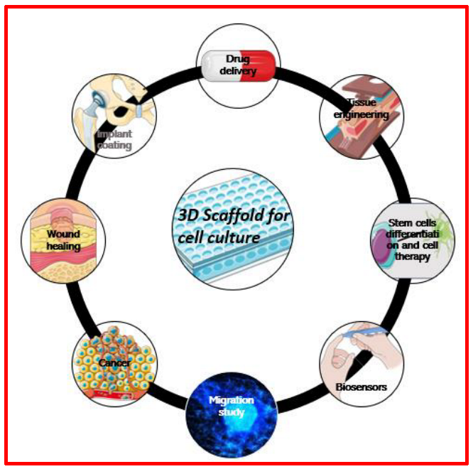
3.1. Why Use Electrospun 3D Scaffolds for Cell Culture?

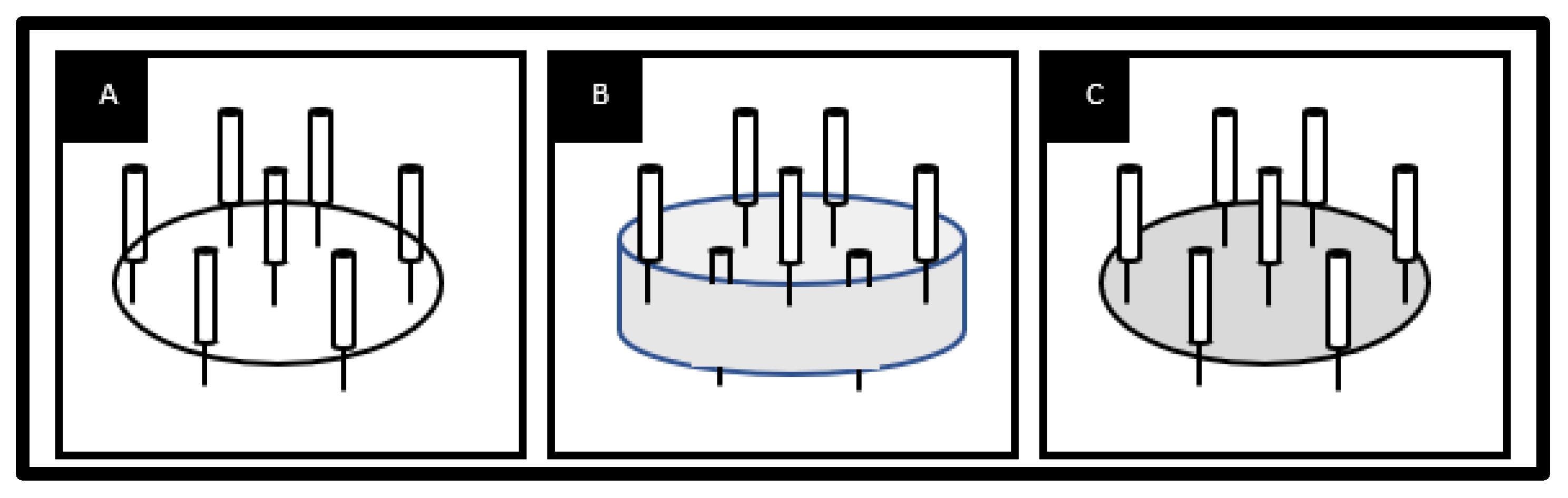
3.1.1. Three-Dimensional Culture vs. Two-Dimensional Culture

When seeded in 2D culture, predictability and results are not representative of what happens in vivo [46]. In fact, cells have been reported to lose their differentiation capacity and develop neoplastic properties, and great differences in transcriptomics are observed. For instance, the expression of 90% of genes involved in cell adhesion, extracellular matrix (ECM) remodeling, and tissue development is excluded in melanoma cells seeded in 2D compared to in vivo 3D tumors [46]. In another study, the 2D culture of GICs imposed an apico-basal polarity, which is not relevant to the concept of GBM and is abolished when cultured in a 3D environment. When seeded on a 3D scaffold, galectin-3 and integrin-β1 were upregulated, which induced the mesenchymal migration of GBM cells, similar to what happens in vivo [47]. Three-dimensional culture, for its part, by better mimicking the physiological environment, allows the differentiation of cells with respect to the tissue of origin. The relevance of results obtained in 3D about cellular morphologies, differentiation and proliferation properties, gene expression, and sensitivity to treatment has been extensively demonstrated while maintaining the heterogeneity of both cells and the transport of nutrients and oxygen [46,47]. One major challenge for tissue engineering and the production of 3D cell culture scaffolds is to produce and monitor a microenvironment that mimics, as effectively as possible, the in vivo ECM, with the fine control of mechanical and chemical properties, allowing limitless imaging and complex analysis with the same convenience as in 2D. Every biological event, such as differentiation, migration, or proliferation, is impacted by the topography of the scaffold and its mechanical, physical, and chemical properties, as well as the availability and conformation of ECM proteins. To better understand cell behavior, it is therefore essential to perform the investigation in an environment as close as possible to the one where each cell type is evolving in vivo [25]. Nevertheless, the current 3D environments available on the market present numerous limitations.

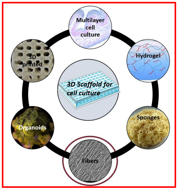
3.1.2. Three-Dimensional Scaffolds

Over the last decade, there has been an increasing number of artificial three-dimensional tissue surrogates developed (Figure 7).
Hydrogels [48], made of highly hydrated polymers, mimic the native ECM environment. They can be made up of natural polymers (such as collagen, chitosan, alginate, and hyaluronic acid) or synthetic polymers (such as PEO, PVA, PAA or P(PF-co-EG), polylactic acid (PLA), poly (lactic-co-glycolic acid) (PLGA), and polycaprolactone (PCL)). Despite their good properties, such as their abundance and high similarity to ECM components for natural polymers or high tunability for synthetic polymers [49], some limitations cannot be ignored. On the one hand, because of too small a mesh area, the reticulation of a hydrogel on cells is necessary [50]. On the other hand, natural polymers have a high rate of biodegradability and are variable, which makes it difficult to compare studies [51]. The polymer’s molecular weight is an important parameter since it determines its activity and its effect on cell behavior and viability. The biodegradation of the polymer leads to a decrease in molecular weight, which induces a complete change in the cell microenvironment [52]. Poorly reticulated hydrogels have too high a degradation rate and do not allow long-term cell culture, whereas highly reticulated hydrogels are too cytotoxic and associated with poor diffusion [51]. Consequently, the physical properties of the environment are difficult to modulate without encountering associated limitations. The homogeneous distribution of nutrients, oxygen, or drug treatments is highly dependent on crosslinking, as it influences diffusion through the hydrogel [53]. Finally, omics analyses are hard to perform on cells seeded on hydrogels. Biodegradation induces the presence of wastes that may impact the results, the treatment steps to harvest cells lead to modifications in gene expression, and the yields of RNA extraction/purification are low [53].
Porous structures can be obtained by freeze-drying or leaching biomaterial solutions [48]. They are called sponges or foam scaffolds. Sponges are extensively used in the context of bone grafts; they permit growth and differentiation and enable simple functionalization [54]. However, their rigidity, porosity, and degradation rate are not easily monitorable or tunable, their visibility in microscopy without cryosectioning is poor, and in the context of cancer, they are not designed to observe migration easily [54].
Ceramic scaffolds are used as biomimetic ECM environments for bone tissue especially. They are highly biocompatible since they are found in natural bone, and they have osteoconduction and osteointegration properties [55]. However, they show lower mechanical strength, and the bone degradation rate is higher than the rate of formation of new bone [54].
Fibrous scaffolds [48] can be obtained by electrospinning, molecular self-assembly, or thermally induced phase separation. Not only do they enhance cell adhesion, growth, and migration, but they also facilitate bioactive molecule diffusion within the scaffold, are biocompatible, show good and tunable mechanical properties and surface chemistry, and have controllable biodegradability [51]. As they are composed of fibers, fibrous scaffolds possess morphological similarities to the native ECM, which is composed of fibers, too (collagen, laminin, fibronectin, hyaluronic acid, etc.) [56]. They are compatible with most microscopy techniques with live imaging and most histology and biochemistry protocols [47]. Studies conducted on decellularized tissues are the closest to the in vivo environment, as they are 3D scaffolds based on the natural ECM, growth factors, and tissues that are specific to the organ where the studied cells come from [57]. However, the availability is low for intact tissues, and it is hardly reproducible since it is particularly challenging to eliminate all cell residues without disturbing the overall organization.
Organoids and spheroids are 3D self-organized and multi-cellular structures [58]. Nevertheless, they cannot be made from every cell type, and they are not suitable for migration studies in a physiological or pathological context alone [59]. Finally, they present low drug penetration due to the absence of blood vessels. In this context, they would have to be combined with a biomimetic environment, such as nanofiber mats or microfluidic devices [59]. For instance, migration studies of neurospheres of GBM were performed on 3D nanofiber scaffolds, and the results were more relevant than neurospheres seeded in 2D [47].

3.1.3. Production of 3D Scaffolds

Three-dimensional printing represents an important advantage since it is assisted by a computer that enables the specific control of every parameter, such as the size and the localization of pores, the architecture, and the mechanical properties. Bioprinting is the printing of hydrogel ink with living cells in it. However, cells must bear stress and pressure during extrusion, and usually, the polymers used have low mechanical stiffness [48].
Electrospinning is the most widely chosen approach since it can provide scaffolds composed of nano- to microscale-diameter fibers, mimicking the native ECM environment at both the micro- and macro-scales [48].

3.2. Choice of Materials

One key parameter to produce a biomaterial is the choice of material, which must be biocompatible. Moreover, to obtain an electrospun scaffold, the substance must be spinnable. Regarding these two criteria, one can choose either a polymer or a peptide, either natural or synthetic.

3.2.1. Polymers

Organic polymers can be electrospun provided that the solvent allows complete dissolution without degradation and that molecular weight is high enough [25].
Natural polymers can be chosen since they are biocompatible, are recognized by cells faster, and have bio-functionality [60,61]. For example, chitosan has antibacterial and hemostatic properties that make it a proper candidate for wound healing. On the other hand, the fibrinogen scaffold presents better mechanical properties and a slow rate of degradation [62].
However, synthetic polymers are usually favored since they are less expensive, present better mechanical properties, and are more easily spinnable [60,61]. PCL, PLA, PGA, and PEO are the most common polymers used for electrospinning scaffolds for tissue engineering. PLA, for example, can degrade into lactic acid, mimics the ECM structure, and presents good mechanical properties. PEO is usually used to study soft-tissue environments [60].
Some polymers, such as polyethylene, are not dissoluble in solvents used for electrospinning [63]. It is melted and kept in this state by heating the needle from which the solution is expulsed. When this happens, the polymer solidifies to form a fiber. One advantage is the absence of solvent residues at the end since this method does not use any solvents. However, this technique does not allow the obtention of nanofibers, and heating can degrade the polymer. Finally, bioactive molecules cannot be incorporated into fibers with this technique.
Finally, composite nanofibers have the advantage of being able to overcome some limitations by combining appropriate properties from the different components chosen [25]. For example, the PVA/chitosan scaffold developed by Agrawal et al. promoted cell proliferation and growth [64]. For the sol–gel solution, hydrolysis, condensation, and gelation reactions are initiated in the jet in contact with the air. It allows the incorporation of an inorganic phase in the fibers [65]. For example, Ag particles, which possess antibacterial properties, were dispersed in a PVA solution and could therefore be electrospun [66].

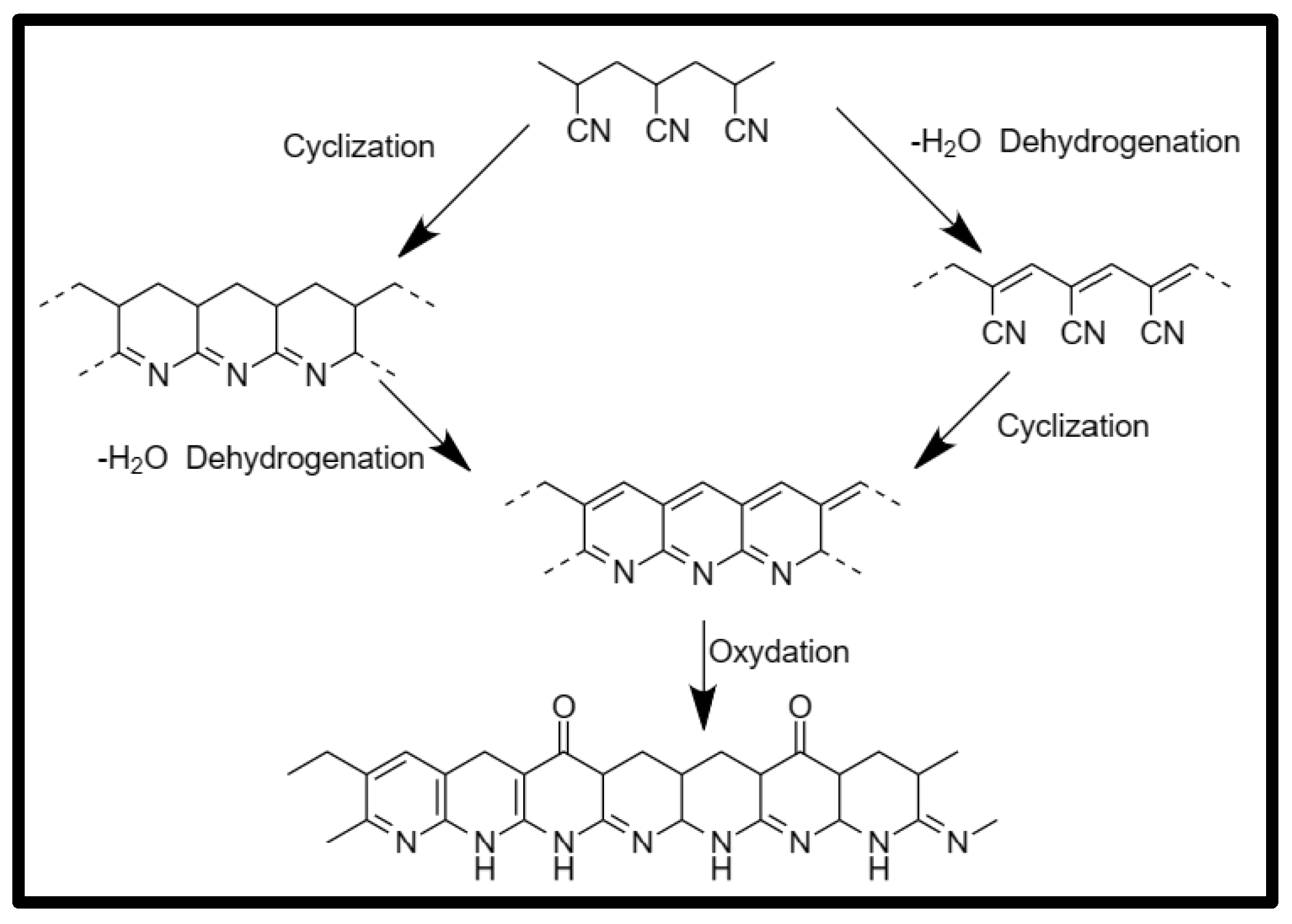
3.2.2. Specific Case of PAN

Polyacrylonitrile (PAN)-based fibers are more suitable precursors to produce carbon fibers compared to other precursors, such as pitch or rayon, due to their high melting point and greater carbon yield (>50% of the original precursor mass). PAN fibers are also used on a large scale in the textile industry as acrylic fibers, and they are highly desirable for high-performance composites for automotive and aerospace technologies due to their enhanced physical and mechanical characteristics [67]. PAN fibers can be used in the biological field to promote cell growth, but so far, they are not widespread in this field. They are selected for their biocompatibility and the possibility of sterilizing them thanks to the thermal treatment that stabilizes their structure [19]. They also show resistance to biodegradation, which not only allows cell culture but also allows complex omics analysis. The spatial design and mechanical properties of PAN nanofibers are tunable, independently of other physicochemical parameters [19]. Finally, most waterproof polymers must be spun from toxic or corrosive solvents, while only some can also be electrospun from low-toxicity solvents like dimethyl sulfoxide. Being spinnable from DMSO is one of the reasons why PAN is often used in electrospinning [13].
  • Electrospinning of PAN
The electrospinning process of PAN has been widely studied in the last few decades [12,13,14,18,68,69,70,71,72,73]. The molecular weight of the most frequently used PAN is 150,000 g/mol. Only two solvents allow the electrospinning of PAN: N, N-dimethylformamide (DMF) and dimethyl sulfoxide (DMSO); the first one is the most used, but, in a few cases, DMSO is used as a low-toxicity solvent [74]. In the DMF solvent, the PAN percentage ranges from 6 to 14 wt.%, depending on the fibers desired. The PAN fiber diameter increases with increasing polymer concentration, just as an increase in voltage, which ranges from 15 to 25 kV, increases the diameter of the fibers. However, the voltage influence is not as great as that of the polymer concentration on the fiber’s diameter. In the case of too low a concentration and voltage, Gu et al. showed that fibers with spindle-like beads were obtained [75]. The collector-to-needle distance is between 15 and 25 cm. Generally, the typical diameter of PAN fiber ranges from 350 to 500 nm, depending on the above parameters applied.
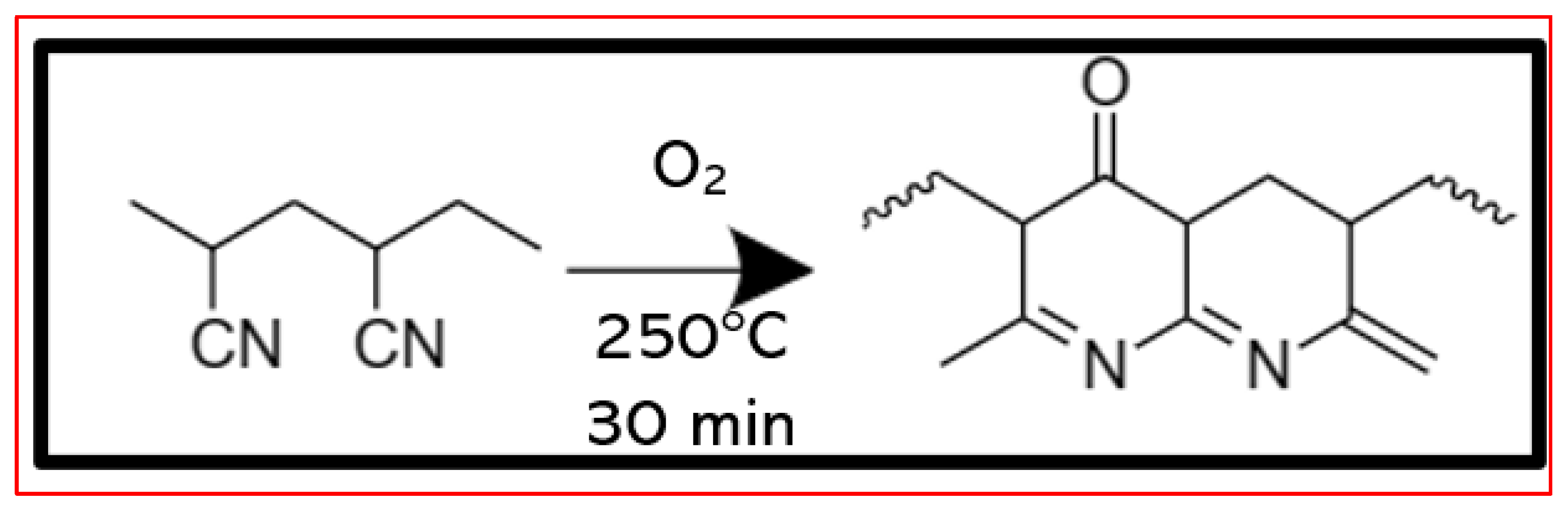
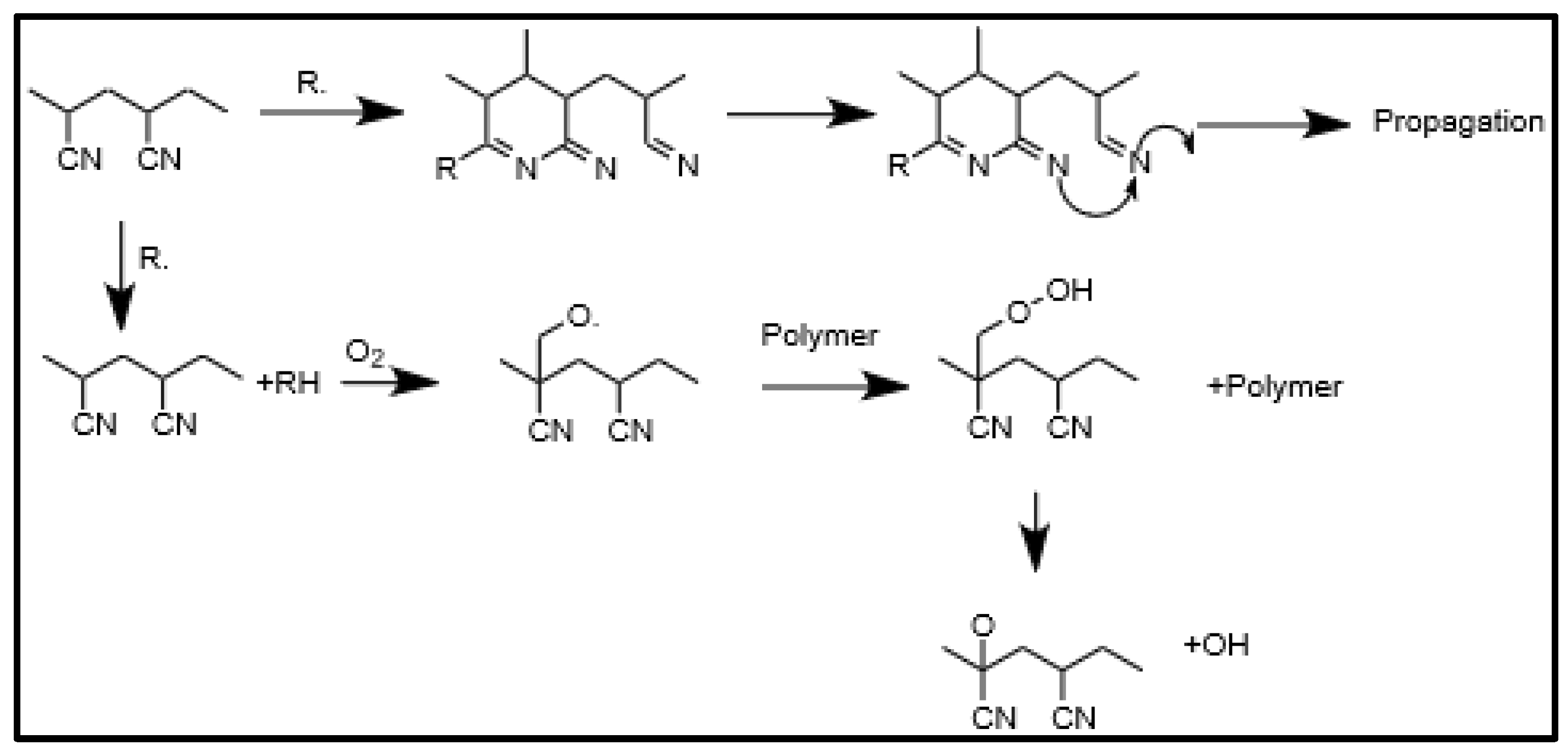
  • Thermal treatment of polyacrylonitrile.
The thermal treatment of PAN, also called thermal–oxidative stabilization (ToS), is an essential and time-consuming step that modifies the original structure of PAN. This can be explained by the chemical reactions that are involved in this process, which are cyclization, dehydrogenation, oxidation, and crosslinking reactions [76]. These reactions lead to the formation of a ladder-like structure, as shown in Figure 8. The order in which the reactions occur has long been discussed. It is now accepted that the cyclization and dehydrogenation reactions can take place at the same time, while the oxidation reaction can only take place after the obtention of the ladder structure [77]. ToS is a complicated stage since different chemical reactions take place at the same time. The step of stabilization converts C≡N bonds to C=N, which results in a non-melting, stable ladder polymer structure from PAN fibers. The thermal stability of the fibers is attributed to the cyclization of the nitrile groups [67]. During stabilization, the PAN fibers change in color, from white mats to yellow and brown to ultimately black fibers, depending on the time and the temperature of the stabilization. This darkening of the color comes from the formation of the ladder structure [78]. In this process, temperature is a key parameter that affects the heat treatment of PAN fibers. It usually ranges from 180 to 280 °C [77,79], and most researchers performed stabilization at 250 °C as an optimal temperature [76,80,81,82]. If the temperature is too high, the fibers can overheat and fuse or even burn. However, if the temperature is too low, the reactions are slow and incomplete, which does not lead to a ladder-like structure. The two most important reactions occurring during the ToS process are dehydrogenation and cyclization because of the structural modification of PAN. Both are important in forming the final structure of stabilized nanofibers [67].
Cyclization
The first reaction is the most important one because cyclization will determine the final PAN fibers’ structure. Cyclization is the reaction of one nitrile group with the following one to form a stable ladder structure. This reaction can be defined by the first-order kinetic equation, and unlike dehydrogenation, the cyclization reaction can proceed in either an inert gas (such as nitrogen) [83,84,85] or the presence of oxygen [86,87]. In other words, oxygen is not involved in the reaction mechanism of cyclization. This reaction is exothermic, and no weight loss is observed during this step [79,80]. This reaction is necessary to hold molecules in the fiber together, and it increases the stiffness. Several sources can be involved in the occurrence of the cyclization reaction. Impurities in the polymer, catalyst fragments, and inhibitors can act as initiators of cyclization. It can also be started at chain end groups [77]. The initiation can start with either a free radical mechanism or an ionic mechanism. The latter takes place when the precursor is a comonomer of PAN, while the free radical mechanism takes place when the precursor is a homopolymer. According to Kim et al., free radicals break C≡N bonds into C=N bonds, which leads to cyclization, as shown in Figure 9. Propagation is relatively rapid in the free radical mechanism [83]. Nevertheless, some nitrile groups fail to convert into cyclic structures during ToS [76].
Fu et al. showed that cyclization is more sensitive to the isothermal temperature than the isothermal time. At 250 °C and 265 °C, 70% and 80% of nitrile groups react to form cycles, respectively. In fact, linear PAN chains convert into cyclic structures by condensation between the two adjacent nitrile groups, which requires the conformation rotation of PAN. The higher temperature provides enough energy to overcome the barrier to the conformation rotation of the linear structure [76]. To summarize, the higher the isothermal ToS temperature, the more cyclic structures form. Ruixue et al. performed eight stabilizations from 220 °C to 280 °C with a step of 10 °C between each sample. They found that the cyclization reaction was complete at a temperature of 280 °C (about 99% of theoretical cyclization), which generates a new intermediate cyclic structure, very similar to the (002) plane of the graphite structure [79].
Dehydrogenation
Dehydrogenation is the elimination of hydrogen with oxygen in the form of water, which leads to the formation of double bonds between carbon atoms. It stabilizes carbon chains by forming aromatic rings. The formation of the double bonds results in an increase in the thermal stability of the polymer due to the decrease in chain scission (Figure 10) [67]. Fitzer et al. used Differential Thermal Analysis (DTA) to show that the dehydrogenation reaction in both air and nitrogen environments can happen before or after cyclization. Because of the use of oxygen in the dehydrogenation reaction, the concentration of oxygen plays an important role in the rate of this reaction. It has been proven that dehydrogenation happens almost at the same time as oxidation [77].
Oxidation
The oxidation reaction plays an important role in improving the thermal stability of fibers by assisting in the evolution of aromatic rings and the conjugated molecular structure. An oxidizing medium is necessary to allow the reaction to take place, which is typically air. Generally, the oxygen content in stabilized fibers ranges from 8 wt.% to 12 wt.% [77]. The oxidation reaction, as well as the dehydrogenation reaction, becomes dominant when the extent of cyclization reaches 70% [76].
Figure 11 shows the complete ToS process.
  • Functionalization of PAN fibers
The functionalization of nanofibers may enhance some properties or even result in new ones. For example, collagen was deposited on a PAN and PLGA scaffold by using the LBL technique. This improved the attachment and spreading of mouse lung fibroblasts [88]. In another study, Wahab et al. used titanium oxide anchored with silver nanoparticles for antibacterial applications. Silver nanoparticles are an efficient alternative to conventional antimicrobial materials and are effective against a wide range of bacteria, viruses, and fungal species. The composite nanoparticles were synthesized using an environmentally green approach using dopamine hydrochloride, which was utilized as an adhesive to form an adhesive coating on the titanium oxide surface, reducing the silver ions into Ag nanoparticles. The Ti/Ag nanoparticles (5 and 10 wt.%) were added to a DMF solution and then sonicated for one hour to make a stable colloidal solution. Then, PAN was added and stirred for 24 h. Nanofiber composites were electrospun with a needle-tip-to-collector distance and voltage of 15 cm and 15 kV, respectively. The nanocomposites showed regular and bead-free nanofibers, and an increase in fiber diameter was observed when using nanoparticles. This has been interpreted as resulting from the localized agglomeration of nanoparticles within the fibers [71].
Engel et al. used gold salt to functionalize nanofibers for catalytic applications. They mixed HAuCl4 and DMF at 70 °C and then added PAN. The mixture was stirred for 3 h at 70 °C and then electrospun. They demonstrated that PAN acts as a reducing agent and is able to reduce gold salt under soft conditions (70 °C) to create nanoparticles, contrary to other polymers, which need extra energy, such as reflux conditions, microwave heating, or UV irradiation for nanoparticle growth [69].
In one study, Patel et al. used a hydrothermal method by electrospinning a PAN solution containing Zn (CH3COO)2·2H2O and AgNO3 precursors. The obtained PAN/Zn (CH3COO)2·2H2O/AgNO3 membrane was mixed with (NH4)2CO3 and transferred into an autoclave for a hydrothermal reaction at 150 °C for 3 h. A PAN/ZnO-Ag composite nanofiber membrane was obtained with good antibacterial properties [72].
Finally, Zhang et al. prepared PAN fibers modified with amidoxime functionalization through the treatment of the mats in a hydroxylamine (NH2OH) aqueous solution. The -C≡N groups on the surface of the PAN fibers react with NH2OH molecules, which leads to the formation of -C(NH2) =N-OH groups (also called amidoxime), which were used for the coordination of Ag+ ions. It is well known that nitrile groups can be chemically converted into amidoxime groups, which can coordinate with a wide range of metal ions, including silver. Subsequently, the coordinated Ag+ ions were converted into silver nanoparticles, with their size being tens of nanometers [73]. Sirelkhatim et al. used these membranes to study the antibacterial effects of amidoxime-Ag nanoparticles on bacteria and fungi to better understand the interactions between the membrane and bacteria [12].

3.2.3. Peptides and Proteins

When peptides and proteins are electrospun, many points must be considered beforehand. Degradation and denaturation are impacted by temperature, humidity, pH, solvent…. Although spinnability is also affected by these parameters for polymers, there is one more element to monitor: the conformation of the protein, which is essential to its bioactivity. The advantages of using these elements are their biocompatibility, their biodegradability, their isoelectric properties, which facilitate drug loading, and finally, their structural properties, which allow them to form ECM structures more easily [89]. Many peptides and proteins have been studied. First, soy protein was used for wound healing. Har et al. showed that scaffolds made with this protein enhanced re-epithelialization in preclinical tests. In addition, silk fibroin presents many advantages, such as biocompatibility, softness, flexibility, brightness, and mechanical properties, among many others, that make it a performant candidate. It was, for example, used for the production of a tubular scaffold to stimulate blood vessel regeneration [89]. One can also find electrospun scaffolds made with hemoglobin, fibrinogen, elastin, collagen, gelatin, keratin, and bovine serum albumin [89].
One strategy for producing more stable scaffolds and electrospinning the solution more easily is to mix proteins/peptides with a polymer. Another strategy is to use synthetic peptides. Studies of scaffolds using them are increasing since they can be manipulated (modification of the amino acid sequence, for example), can be used without toxic solvents, and are more easily spinnable [89].

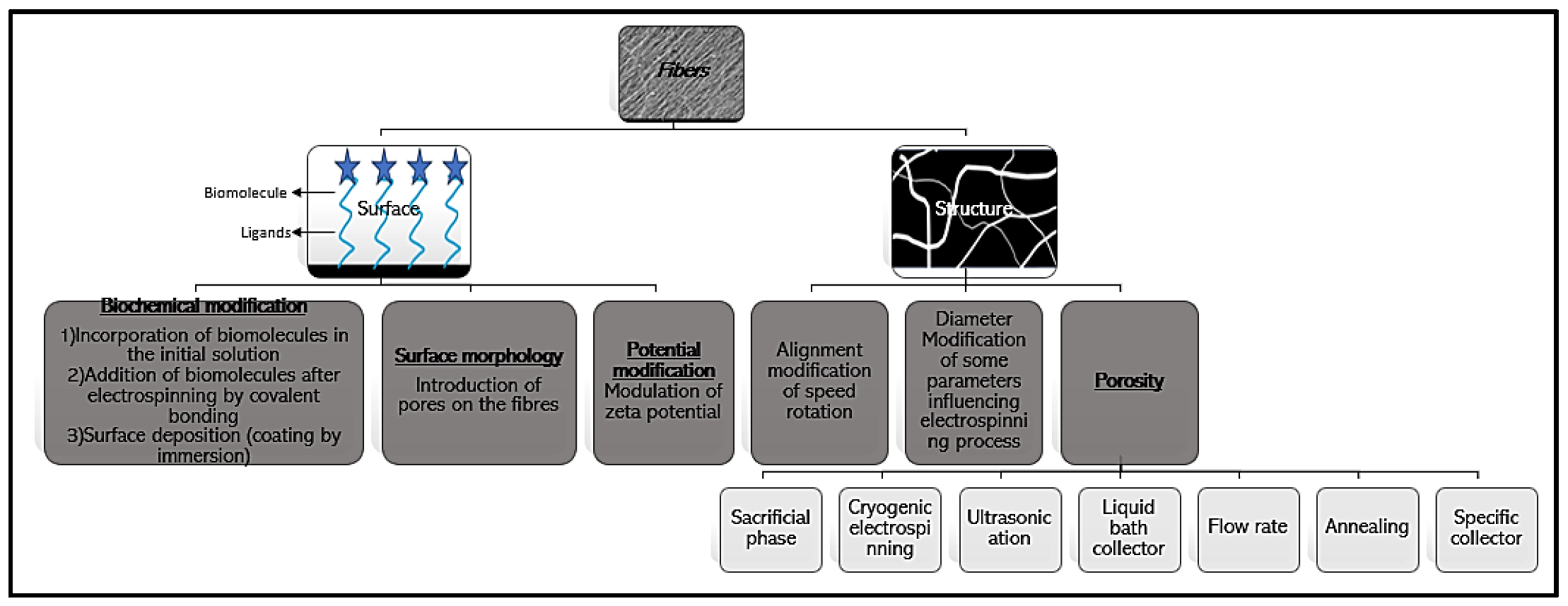
3.3. Control of Scaffold Architecture

The ECM plays a significant role in cell behavior. To better mimic this environment, it is necessary to produce scaffolds with specific surface properties and an accurate architecture. The scaffold surface can be modified by chemical treatment, and its structure can be controlled and modulated through different structural approaches (Figure 12).

3.3.1. Modification of the Surface

The surface has a significant impact on cells since their interactions influence the activation of signaling pathways and thus migration, differentiation, and proliferation. Thus, surface morphology and potential, as well as the functional groups present on the surface, must be well controlled to fully understand the mechanisms involved.
  • Biochemical modification
Incorporating biomolecules or nanoparticles into electrospun nanofibers provides additional functions and enhanced performance. The biomolecules can be proteins, peptides, or plant extracts, for example. The nanoparticles can be made of metals [71], metal oxides [13,90], metal salts [70], graphite [90], or even one-dimensional (1D) nanostructures, such as carbon nanotubes [91]. The commonly used nanoscale components include nanoparticles made of Ag [12], Au [70], Zn [13], and Ti [71].
Two strategies, not necessarily mutually exclusive, can be employed to modify the scaffold surface [60].
The first strategy is to incorporate biomolecules within the initial solution. The electrospinnability of such a formulation depends on the type, size, and concentration of the added components, which will also affect the morphology and properties of the resultant electrospun nanofibers. A stable dispersion of the nanoscale components in the polymer solution is necessary to obtain a homogeneous distribution of the nanoscale components [34]. For example, the functionalization of PCL nanofibers with galactose biomolecules improved the secretion of collagen and glycosaminoglycan, as shown by Nemati et al. [60]. Another example is silver nanoparticles added to MADO nanofibers to induce antibacterial properties that were not observed in pure MADO scaffolds [92]. In another study, Wehlage et al. [13] investigated the nanomaterial composite PAN/maltodextrin/pea protein (PAN/MP) and PAN/casein/gelatin (PAN/CG) in order to improve cell adhesion to PAN. Blending PAN with additives improves cell binding. All solutions were prepared by stirring PAN with casein/gelatin and maltodextrin/pea protein for 2 h at room temperature. Afterward, they were sterilized by autoclaving for 20 min at 121 °C to promote cell growth. These blends were found to result in larger fiber diameters (around 600 nm) than pure PAN nanofiber mats. It appears that the preparation process, such as autoclaving, among others, influenced the PAN/CG nanofiber morphology, likely by denaturing proteins and melting gelatin during heat treatment. Nevertheless, they enabled cell growth and adhesion. The best cell proliferation and adhesion, however, was found in PAN/CG nanofiber mats.
The second strategy is surface modification after electrospinning by adding chemically and/or physically bioactive molecules and ligands. Plasma treatment introduces polar functional groups that enhance wettability, polarity, and protein adsorption and improve cell behavior. For example, the capture of porcine mesenchymal stem cells on PLLA nanofibers was improved after oxygen plasma treatment [93]. Coating is another way to modify surfaces by introducing hydrogen bonding, Van der Waals interactions, and π–π stacking [60]. For instance, it was shown that, by coating PDA on PLA nanofibers, hADSC adhesion was promoted [94]. Also, Electrostatic-Template-Assisted Deposition is a new method allowing the spatially controlled deposition of biomolecules on electrospun nanofibers. When nanofibers are on the conductive part of the collector, electrosprayed HA particles are deposited on them, whereas they do not reach nanofibers on the non-conductive part of the collector [95]. Layer-by-layer (LBL) is another method based on the adsorption of oppositely charged particles due to electrostatic forces, hydrophobic interactions, and covalent bonding [88].
Finally, concerning the nanoparticles, they can be generated on the surface of electrospun nanofibers through surface deposition, in situ synthesis, or hydrothermal treatment. The simplest method is to immerse the as-spun nanofibers in a colloidal suspension of nanoparticles to capture the nanoparticles through chemical or physical binding. A requirement is that the nanofibers are not soluble in the colloidal suspension [34]. A coating allows, for example, the formation of gradients to improve cell polarization or the direction of migration. Karl et al. showed the preferential direction of RGC axons toward a higher concentration of Netrine-1, which is promising for diseases of the optical nerve [96].
  • Surface morphology and potential modification
When cells interact with the scaffold, signals are transduced to the nucleus, triggering signalization cascades [91]. Recently, Metwally et al. produced electrospun PCL scaffolds with different surface potentials and different morphologies. They could compare the impact on the cells of either porous or smooth fibers composing the scaffold. Then, by changing the voltage polarity during electrospinning, they modified the surface charge and zeta potential of the fibers. They showed that bone regeneration was enhanced when fibers were porous, the surface potential was higher, and the zeta potential was negative. Porous fibers promoted initial cell adhesion, a higher surface potential improved collagen mineralization, and finally, a negative zeta potential enhanced calcium mineralization [97].

3.3.2. Modification of the Structure

  • Alignment
Alignment is a key factor to monitor. Some tissues show naturally oriented arrangements, such as blood vessels [60]. For example, Cho et al. observed that the formation of myelin-like segments from induced pluripotent stem cells was promoted on well-aligned PCL nanofibers [98]. Sometimes, both aligned and non-aligned fibers can be necessary. Park et al. [93] created a scaffold with one layer of aligned fibers that promoted the alignment and differentiation of C2C12 myoblasts and one layer of non-aligned fibers that resulted in good mechanical properties. To control alignment, a mechanical treatment can be performed to force the orientation of the fibers. However, this method can break the fibers. Thus, the modification of the collector shape or the speed of rotation is usually the method used to modify the fiber alignment [99].
  • Diameter
The diameter is another factor to control. According to the cell type, the diameter must be changed to better mimic the microenvironment of cells and thus induce in vivo cell behavior [100]. Migration, cell adhesion, and proliferation are impacted by the fiber diameter. For instance, 3T3 fibroblast adhesion is promoted on 428 nm nanofibers, whereas a larger diameter is required for platelet attachment. Also, the diameter impacts gene expression and the cell phenotype. For example, osteogenic genes were upregulated on nanofibers compared to microfibers [100]. Han et al. showed better smooth muscle vascular cell proliferation on 500 nm nanofibers compared to 1 μm fibers [101].
  • Porosity
* Phase separation
The introduction of pores can be induced from a biphasic medium by transforming one phase into pores and the other into a nanofibrous matrix. Separation can be achieved between the polymer and solvent or the polymer and non-solvent [102,103].
The first method is induced by very quickly cooling the not fully solidified jet by evaporating a very volatile solvent or by collecting the nanofibers with a cryogenic liquid. Thus, by using THF, chloroform, or acetone as solvents, porous nanofibers of PMMA, PS, PCL, cellulose acetate, or poly (vinyl butyral) were obtained. Similarly, PS nanofibers with a high pore density were obtained by collecting the fibers in a liquid nitrogen bath followed by vacuum drying [104].
The second method is induced by vapor or liquid phase separation. For vapor-induced separation, electrospinning is performed under humidity, and the water molecules in the air act as a non-solvent. The solvent evaporates, and the water vapor condenses into exceedingly small water droplets. Polymer-enriched and polymer-depleted domains are thus formed. The former domain solidifies to become the nanofibrous matrix, and the latter forms the pores upon the evaporation of water and the solvent. Porous nanofibers of PVDF, poly (ether imide), PET, and PS were produced in this way [104].
Another method is the collection of fibers in a non-solvent bath. The residual solvent, in contact with the non-solvent, induces phase separation and pore formation. Thus, by electrospinning a solution of PAN/DMF in an ethanol bath, porous PAN nanofibers were produced, whereas solid nanofibers were produced by electrospinning the same solution in hexane [105].
* Use of a sacrificial phase
Small molecules (e.g., salt), copolymer blocks, polymers, or nanoparticles can function as a sacrificial phase and be removed via leaching or calcination.
The sacrificial polymer must be water-soluble. By varying the ratio of the matrix polymer to the sacrificial polymer, the pore size can be varied. PEO is one of the best candidates for the sacrificial phase [106]. In one study, porous carbon nanofibers were formed by carbonizing PAN and Nafion nanofibers. Thus, PAN was converted to carbon, and Nafion was decomposed. In another study, coaxial electrospinning was used to generate porous TiO2 nanofibers. The inner phase was PS in DMF and THF, while the outer fluid was PVP in ethanol containing Ti(OiPr)4. The two solutions partially mixed in some regions of the jet, and rapid evaporation of the latter separated the two polymers. Then, a continuous matrix of PVP and TiO2 formed, with nanoscale domains of PS in it. After calcination, porous TiO2 nanofibers were finally obtained by removing PVP and PS [107]. Sadeghi-Avalshahr A. et al. used PVP as a sacrificial fiber to increase the pore size and improve cell infiltration. PCL and PVP solutions were electrospun simultaneously using two independent needles placed opposite from each other. The resulting fibers were placed in water for PVP dissolution. The fibers were then grafted with collagen and chitosan. This allowed HDF cells to infiltrate the matrix [108].
* Salt leaching
To create a controlled pore size, salt particles with known sizes can be dispersed in the polymer solution before electrospinning and leached out after [106]. Nam et al. introduced salt particles using a sheath around the needle. The resulting PCL nanofibers exhibited a uniform network with well-dispersed salt particles [109]. Kim et al. simultaneously deposited salt particles and electrospun nanofibers, producing a porous network of hyaluronic acid and collagen. After salt leaching, the structure of the matrix is minimally affected (slight shrinkage is observed) [110].
* Cryogenic electrospinning
For this method, the collector system must be kept at a low temperature to allow the formation of nanofibers and crystals and thus form a fibrous mesh containing crystals that are then removed by freeze-drying [25]. Pores are thus obtained and can vary according to the number of crystals formed and the size of these crystals depending on the humidity [111]. For example, NIH 3T3 fibroblasts were able to infiltrate a porous poly (D-L, lactide) matrix obtained by this method, while this was not the case in a conventionally obtained matrix [112].
* Combination of nano- and microfibers
This combination produces larger pores with greater interconnectivity. While nanofibers improve cell adhesion and proliferation, microfibers have larger pore sizes that facilitate cell infiltration [113]. This type of matrix can be obtained by simultaneously electrospinning microfibers and nanofibers using two different needles. Pham et al. thus generated a PCL matrix composed of microfibers (5 μm in diameter) and nanofibers (600 nm). The large pores allowed cells to infiltrate the matrix, and the nanofibers facilitated cell distribution and growth. It was shown in this study that stem cell differentiation was impacted [114].
* Ultrasonication
To increase pore size, ultrasonication is a possibility since it allows the scaffold to be loosened [115]. Exposure time and energy are the two parameters that influence the pore size obtained. Gu et al. demonstrated that electrospun chitosan fibers that underwent ultrasonication allowed greater proliferation and infiltration of human dermis fibroblasts [116].
* Liquid collector bath
The obtention of large pores can be achieved by using a liquid reservoir since the fiber dispersion is increased, and thus, fiber binding decreases [106]. Yang et al. produced PLGA/PCL matrices using an ethanol bath. BMSCs infiltrated the matrix and deposited it on a cartilage-specific matrix. The matrix was then implanted subcutaneously in rats, and bone formation was observed after 8 weeks [117].
It is also possible to generate a yarn structure by using a dynamic liquid system. A vortex of water is created that twists the nanofibers deposited on the surface of the water and forms a continuous thread. These threads can be collected on a rotating collector to form a 3D array of aligned nanowires. Xu et al. used a P(LLA-CL)/collagen matrix obtained by this method for tendon regeneration [118].
* Annealing
Annealing consists of heating a polymer above its glass transition temperature and then cooling it. Porosity, hydrophobicity, mechanical properties, and molecular structure are impacted [119]. PLA was electrospun on a rotating collector at 100 rpm to obtain an isotropic matrix. Then, the matrices were placed between two glasses and heated in a muffle furnace under different annealing conditions. First, the annealing temperature was set at 90 °C and the time varied (30 to 120 min), and then the time was set at 30 min and the temperature varied (90 to 105 °C). As the annealing time increases, the pore size decreases due to shrinkage, fiber thickening, and fiber melting. By increasing the annealing temperature, the fibers thicken, the pore size decreases, and the fibers fuse together. The annealing treatment increases the fusion between fibers and the degree of crystallinity but decreases the ductility [119].
* Influence of flow rate
Rnjak-Kovacina et al. [120] studied the impact of the flow rate on the porosity of their tropoelastin scaffolds. Two different flow rates (1 and 3 mL/h) were used. They showed that the fiber diameter, thickness, porosity, and pore size increased with the flow rate. The cells proliferated on both matrices, but they only infiltrated the scaffold when seeded on the one obtained at 3 mL/h. Also, the fibroblasts seeded on this matrix deposited collagen and fibronectin, thus showing the capacity of the cells to proliferate and modify their environment. When the matrix was injected into rats, an early stage of angiogenesis was observed, and no negative immunological response was produced.
* Specific collectors
To influence the pore size, the deposition support of fibers can be modified [106]. For example, Blakeney et al. [121] demonstrated that the use of a spherical foam collector with stainless steel probes results in a relaxed, uncompressed, cotton-ball-shaped matrix. The proliferation and infiltration of INS-1 cells were improved. Another method is to use airflow pressure, whose velocity influences the pore size by loosening electrospun fibers [106]. For example, a specific collector was created by Liang Chen et al. [122] to produce fibers with a controlled microstructure by controlling the speed of this collector. This collector has five microcontrollers, four micro-stepper drivers, and four collecting surfaces. The hexagonal needle produces an identical electric field at each vertex of the needle, improving the homogeneity of the formed nanofibers. They studied four different speeds. The pore size was found to increase with the speed. The authors studied the behavior of pre-osteoblastic MC3T3-E1 and pre-osteoclastic RAW 264.7 cells that participate in bone regeneration. They were able to observe that MC3T3-E1 survived best in the matrix with the largest pore size, while RAW 264.7 survived best in medium-pore-size nanofibers. The large-pore-size nanofibers promoted the differentiation of pre-osteoblast cells.

3.4. Application in Biological Field

3D scaffold for cell culture can be used for different applications, summarized in Figure 13, such as drug delivery or tissue engineering. Each field is developed after this figure.

3.4.1. Studying Migration

Cell migration is divided into steps (polarization, actin polymerization, assembly, and disassembly of focal adhesions) that lead to cellular spatial asymmetry and cell body translocation [19]. Environmental chemical and physical properties lead to a variety of signals, triggering signalization cascades and ultimately impacting migratory behavior: single or collective, amoeboid or mesenchymal, focal-adhesion-independent or focal-adhesion-dependent, and directionally persistent or not. In contrast to single-cell migration, during collective migration, cells will be influenced both by cell–cell junctions (described as implicated in mechanosensing and signaling) and by extracellular matrix stiffness sensed at integrin focal adhesions or thanks to mechanosensitive ion channels, leading to the modulation of migration, depending on ECM properties.
Different kinds of nanofibers have been made to reproduce, individually or in association, different physical and chemical parameters found in vivo.
In cancer, the alignment of ECM fibers has been extensively described as modified by the tumor growth itself, ECM remodeling by cancer cells, and the imbalance between ECM protein production, degradation, and crosslinking. All those events lead to the creation of a tumoral microenvironment that promotes cell migration, called a desmoplastic environment, and causes ECM protein composition changes, fiber alignment, and an increase in stiffness. When cancer (and healthy) cells are cultivated on a desmoplastic-like nanofiber configuration, the cells migrate along the nanofibers, and the migration speed is increased [19]. In contrast, on non-aligned nanofibers, the cells migrate in all directions, and translocation takes place over a short distance.
The ECM composition and protein abundance have a profound impact on cell behavior and migration as well. ECM cell receptor expression is co-regulated with ECM changes observed in physiological and pathological contexts, and different ligand/integrin combinations significantly change the traction force exerted by the cells, adhesion formation, and the following mechanosignaling [123]. The adhesion force must therefore be neither too strong nor too weak to optimize and adapt cell migration within the microenvironment. If ECM proteins are low in abundance or the ligand/integrin combination does not correspond, cells adapt their migration behavior. In the publication by Saleh et al., the behavior of glioma stem cells expressing mainly collagen receptors was compared between two conditions: migrating in an in vitro laminin-coated nanofiber environment and then when xenografted in the mouse brain (collagen is not abundantly naturally expressed in the brain) [47]. Then, GSCs appeared to migrate collectively to escape anoikis (death by cell detachment of ECM matrix), both on nanofibers and in the mouse brain. Consequently, the coating of nanofibers with proteins greatly affects cell behavior and migration, modulating migration behavior both in vitro and in vivo [25,124]. Also, a gradient of bioactive agents can guide migration, thanks to chemotaxis, with cells preferring to migrate along the gradient toward a higher ECM protein concentration. The dependence on ECM proteins or other bioactive agents for migration was also shown by enabling competition between a BSA gradient and a bioactive agent deposited at a lower concentration by electrospraying within a microfluidic device or by electrohydrodynamic printing [125].
Mechanical cues such as stiffness have been observed many times to influence migration, both in 2D and in 3D, and also occur during cell migration on nanofibers with different stiffnesses. Marhuenda et al. [19] used PAN nanofibers stabilized at 250 °C for two hours with stiffness modulations to study glioma stem cell migration in a 3D fibrillary environment depending on rigidity. They modified the stiffness of nanofibers by adding multiwalled carbon nanotubes (MWCNTs) in the polymeric solution before electrospinning, which modified the intrinsic Young’s modulus of PAN fibers. They obtained and selected electrospun fibers with stiffnesses ranging from 3 to 1260 kPa, which are values reported for healthy human tissues and gliomas [126]. It appears that the number of MWCNTs is independent of the fiber diameter, and 166 kPa fiber stiffness was found to be optimal for glioma stem cell migration, increasing the migration rate by ~4 [19]. Values around 100 kPa were previously described as optimal for migration by Bangasser et al. [127]. Also, between 3 and 1260 kPa was found to be the range of stiffnesses that can be used for the culture of other cell subtypes in order to ensure a suitable environment in terms of stiffness [128].

3.4.2. Cancer Research

Although 2D scaffolds are routinely used in cancer studies, it is well known that the results obtained are often far from reality and can be misleading. Cancer tissue engineering in 3D nanofiber scaffolds better mimics reality than 2D scaffolds [129], and the focus is currently on reducing animal models thanks to pertinent in vitro 3D matrix modeling of the cancer microenvironment. These scaffolds are used to study drug delivery, to isolate CTCs, and to study modifications in cell behavior due to chemical or physical changes in the environment. One of the differences between 2D and 3D scaffolds is access to nutrients. In 2D scaffolds, nutrients are uniformly distributed, while a spatial gradient is observed in vivo, especially for cancer cells due to the stiffening of the tumorous environment [45].
Nanofiber materials are produced with properties mimicking, as closely as possible, those found in tumor environments and with the aim of reproducing ECM interactions with cells cultivated on fibers. It is well known that cancer cell proliferation and migration are impacted by ECM stiffness and ECM composition [130,131,132], as well as the tumor grade, aggressiveness, and drug resistance. Chitosan/poly (ethylene oxide) nanofiber scaffolds have shown remarkable results as well. When MCF-7 breast cancer cells were seeded on them, 3D breast cancer tissues were formed after 10 days with a higher proliferation rate than what was observed in conventional 2D adherent plates [133].
In another study, Saha et al. produced electrospun PCL scaffolds with either aligned or non-aligned fibers. The MCF-7 cells seeded on them showed different morphologies in two environments (elongated shape and flat stellar shape, respectively), highlighting the fact that the topography of the fibers has a great impact on tumor cell behavior [134]. Ricci et al. showed that PDAC cells (pancreatic ductal adenocarcinoma) had different behaviors depending on whether they were seeded on a nanofiber scaffold or a sponge scaffold. In the case of PDAC, a spongy scaffold seemed to increase proliferation compared to a fibrous scaffold. The secretion of matrix metalloproteinase (MMP) appeared to change depending on the material composition of the sponges (poly (vinyl alcohol)/gelatin (PVA/G) mixture and poly (ethylene oxide terephthalate)/poly (butylene terephthalate) (PEOT/PBT) copolymer), but it was secreted in both sponges and fibers [135]. Kim et al. were able to co-grow BM-DC (bone marrow dendritic cells) and CT26 (colon cancer cells) and reproduce the crosstalk in vivo happening in between those cells. BM-DC, chosen as the immune cell model and presenting antigens to T cells, could swallow up mitoxantrone-treated CT26 cancer cells, as would have been the case in vivo. These co-cultures could then serve as wonderful in vitro models of the engulfment of cancer cells by T cells [136]. Jain et al. proved that glioblastoma cell (U87) migration was promoted on aligned fiber scaffolds [137]. This enhancement of migration could be used to guide glioblastoma cells away from the primary tumor trap thanks to topo-induction and attract them in an extracortical trap, where they would be more accessible. This would thus enable more efficient operations.
The primary culture of human glioma stem cells (GSCs), when deposited on poly acrylonitrile nanofibers (PAN) by A. Saleh and E. Marhuenda, appeared to be capable of modulating their migration behavior. These migration modulations, individual or collective, depended on the presence of a laminin coating on the surface and ECM receptor expression by the GSCs and recapitulated the migration behavior observed in vivo with the xenograft of those same GSCs. In addition, a transcriptomic assay performed in 3D, compared to the classic 2D assay, exhibited 98 deregulated genes implicated in the cell cycle and proliferation and in the kinesin family, suggesting a shift to an aggressive and invasive phenotype [47].
E. Marhuenda et al. investigated the migration of GSCs deposited on 3D PAN nanofibers, depending on the microenvironment stiffness. The stiffness of the nanofibers was tuned through the addition of MWCNTs, from 6 to 1260 kPa. The GSCs were found to migrate 4 times more at 166 kPa than at other stiffnesses and were associated with the higher expression of invasiveness markers. This exhibits the existence of an optimal stiffness for migration within 3D nanofiber mats. This optimal stiffness even appeared to be able to trigger migration by itself in proliferation conditions. This optimal stiffness very likely depends on the cell type [19].
Another possible use of nanofibers is immunosensing for cancer screening. It is a way to detect tumor markers or circulating tumor cells in the blood at an early stage of cancer development [25]. By functionalizing nanofibers with bioactive molecules (such as enzymes or antibodies), specific cells can recognize them and adhere. Ali et al. created a zinc oxide electrospun nanofiber scaffold decorated with EGFR-2, allowing the detection of breast cancer biomarkers for early diagnostics. This system, based on the electrochemical impedance technique, rapidly detects 1 Fm concentration [138].
Another example is a scaffold made of ZnO nanofibers containing MWCNTs and conjugated with the anti-carcinoma antigen-125 antibody (carcinoma antigen-125 is a specific marker for ovarian cancer [139]). Similarly, an oxygen sensor was created by combining PCL nanofibers with oxygen-sensitive ruthenium [140].
The capture of CTCs could allow the slowing down and prevention of metastasis, as well as the obtaining of information to better diagnose cancer and analyze the effectiveness of drugs. CTCs (HeLa, KB, A549, and MCF-7 cells) were specifically captured in a microfluidic chamber by PLGA nanofiber arrays coated with hyaluronic acid (CD44 receptors for hyaluronic acid are overexpressed in many cancers) in the study of G. Xu et al. [141]. The captured HeLa cells continued to grow on the nanofibrous membranes in the microfluidic chip without compromising cell viability, making it promising for individualized medicine research. By capturing CTCs, drugs could be assessed and monitored in real time.
pH plays a central role in many biological processes and particularly in cancer. To quantify and perceive this biological parameter, organic hybrid electrospun nanofibers were filled with pH-sensing capsules. They changed optically when subjected to proton-induced switching. This change was analyzed with fluorescence detectors and led to the quantification of the local proton concentration. It would be interesting to use this kind of pH-sensing electrospun fiber to measure, both spatially and temporally, extracellular pH in vivo to study glycolysis (inhibiting anticancer drugs) [142].

3.4.3. Biosensors

Biosensors are essential for the detection, quantification, and monitoring of analytes to provide an accurate and performant treatment [143]. First, electrospun nanofibers have been used to detect DNA. By electrospinning cellulose monoacetate and tetraethyl orthosilicate, DNA molecules were able to be captured on the surfaces of fibers. This allowed the researchers to electrochemically monitor guanine-base oxidation in single-strand DNA [143]. Another electrochemical biosensor was created to detect early-stage Alzheimer’s disease. By functionalizing a carbon electrode with electrospun tin oxide nanofibers, hormone-specific β-Amyloid was immobilized and could be titrated. Its absorption on the nanofibers induced a reduction in conductivity [143].
Hydrogen peroxide detection is of great interest, especially for early-stage cancer diagnosis. Daemi et al. used a ZnO-CuO hybrid nanofiber to detect H2O2 by analyzing the charge transfer resistance and electrocatalytic performance [143].
Electrospun nanofibers can also be used as sensors of glucose, and PAN nanofibers can be used to produce glucose biosensors. Electrospun PAA/PAN/AuNP nanofibers allowed the monitoring of glucose levels with better sensitivity than the screen-printed carbon electrode by itself [144]. Highly sensitive and long-term stable glucose sensors have been fabricated by encapsulating enzymes into ZIF-8/CA nanofibers and then coated with MWCNTs and AuNPs to form an electrode [143].

3.4.4. Stem Cell Differentiation and Cell Therapy

Stem cells are promising for new medical treatments, and regenerative medicine offers great hope for the repair response after injuries or diseases. Stem cells or precursor cells can differentiate into many cell types, depending on their physical and chemical microenvironment. To regulate the proliferation and differentiation of stem cells, matrices are made to mimic stem cell niches. Gooraninejad et al. [145] used PAN nanofiber scaffolds as supports for cell therapy by allowing the proliferation and differentiation of stem cells. They seeded human endometrial cells on PAN nanofibers, inducing their differentiation into PDX1-expressing cells, and then transplanted them into diabetic rats. They showed that both the weight and blood glucose levels of diabetic rats decreased. Although more studies are necessary, this could be a promising treatment for diabetics. As mentioned previously, physical parameters of the microenvironment, such as surface topography, dimensions, and mechanical properties, can impact cell differentiation. MSC-derived iPSC cells differentiate better on aligned nanofibers [146].
Mechanical properties have a particularly important impact. For example, when reducing the matrix thickness of gelatin and Tecophilic nanofibers, SMCs (smooth muscle cells) differentiate into cells with a contractile phenotype, and SMC proliferation is reduced.
Finally, biological signals such as growth factors, proteins, and peptides can be incorporated into the matrix to direct stem cell differentiation. For example, adipose cells derived from MSCs were co-cultured with human tenocytes and umbilical cord endothelial cells on a scaffold made of interlaced PCL and PLA nanofibers. The cells expressed higher activation of tendon-associated markers than on PCL nanofibers alone. A matrix fabricated by electrospinning serum albumin, doped with hemin, and then functionalized with proteins and growth factors has a favorable microenvironment, providing guidance topography, bioactive molecules, and potential electrical stimulation. This matrix has been shown to be effective in promoting the differentiation of iPSC cells into neurons.
However, stem cell culture on a biocompatible scaffold, promoting their differentiation preceding transplantation, remains a challenge.

3.4.5. Tissue Engineering

A scaffold for tissue engineering is a structure made to facilitate the growth, proliferation, and differentiation of cells. It is supposed to work as a framework for tissue formation and can be implanted into a patient. The creation of tissue by seeding cells on electrospun nanofibers has already been evaluated for bone regeneration, neuroscience, and skin reconstruction.
For tissue regeneration, growth factors are required but are unstable and have a short half-life. Their incorporation into nanofibers would allow them to maintain their activity and stabilize them. Promising results have been obtained with fibroblast (FGF), epidermal (EGF), transforming (TGF), neural (NGF), platelet (PDGF), connective tissue (CTGF), and vascular endothelial (VEGF) growth factors [147]. Qu et al. encapsulated BSA and transforming growth factors (TGF B3) in PCL/PLGA nanofibers. This matrix could then induce the differentiation of synovium stem cells into fibrocartilage tissue [148].
The creation of Shape Memory Polymer (SMP) nanofibers is interesting for tissue engineering, specifically to minimize invasive surgery [149], and magnetic nanofibers are also of interest, as magnetic stimulation allows the alignment of cells on a magnetic matrix [150].
Wieringa et al. were able to show the effect of the synergistic action of different peptides (P20 and RGD, among others) on neurite and glial growth [151]. This illustrates the interest in functionalizing heterogeneous scaffolds to study cell behavior in more accurate models of the ECM and to better understand the complexity of the biological system in which cells evolve.
  • Bone tissue engineering
Nanofiber scaffolds offer a more optimized environment than other 3D cell culture systems for cell attachment, osteoblastic differentiation, mineralization, and bone regeneration [61]. Electrospinning allows the customization of scaffolds and provides them with the appropriate mechanical properties and high porosity [152]. Wang et al., for example, used a PLLA solution incorporated with PHBV to be electrospun for bone tissue engineering. The combination of both polymers offered shape memory properties and good mechanical properties [153]. Another study presented electrospun PAN/nCB/HA nanofibers, an excellent candidate for bone and other hard-tissue engineering. HA was used to better mimic the natural bone environment, and nCB (carbon black nanoparticle) improved the mechanical properties of the PAN/HA scaffold. The full combination enhanced MC3T3-E1 osteoblast cell proliferation and adhesion [154].
To promote the regeneration of tissues, matrices often combine a biocompatible polymer with an inorganic phase [25]. Matrices of PLA, PCL, and PEO fibers contain large and interconnected pores and have been shown to allow the osteogenic differentiation of MSCs. The addition of minerals and bioactive agents enhances the ability of the scaffold to promote differentiation.
Some biomolecules can be added to promote cell activation and cell growth. For example, Rachmiel et al. [155] electrospun a solution of PCL and hyaluronic acid (HA) that led to enhanced osteogenic differentiation. More recently, an electrospun PA6/CS scaffold was functionalized with HA particles. PA6 mimics collagen, and the biodegradation rate of CS, present in the ECM, is quick enough to ensure new bone formation. Finally, HA, which was mineralized, enhanced MC3T3-E1 cell attachment and proliferation. All these results make it a promising candidate for bone tissue engineering. The functionalization of electrospun PCL nanofibers with E7 and BMP-2, two mimetic peptides found in the native bone ECM, promoted BM-MSC adhesion and osteogenic differentiation. Also, it was shown that PAN nanofiber scaffolds including Ag particles allow osteoblasts to survive and proliferate. Ag’s biocompatibility, antibacterial properties, and ability to be sterilized make it a suitable candidate for a prosthesis with double function (one side for bone regeneration and the other side for soft-tissue repair).
For many centuries, plant extracts, essential oils, and other phytoconstituents (such as Lemongrass, Baicalein, or cinnamon) have been used to treat diseases because their properties help the repair and/or regeneration of hard tissues [155]. Electrospinning these constituents allows their potential to be exploited. For example, Panax ginseng incorporated into PCL nanofibers improved the proliferation of mesenchymal stem cells and induced osteogenic gene expression [155]. Curcumin is also known for its benefits in bone regeneration.
One of the main properties of bone tissues is piezoelectricity because of collagen micelles [152], inducing bone growth and regeneration. Kitsara et al. produced a scaffold made of electrospun PVDF nanofibers treated with oxygen plasma. Voltage-gated calcium channels were stimulated, thus promoting cell activation [153]. Carbon nanofiber matrices made by electrospinning PAN, followed by calcination and carbonization, showed promising results for the stimulation of bone tissue regeneration when applying an electric current, as well. MG-63 cells were cultivated onto these matrices, and an electric current was applied, concentrating on the highly conductive CNFs. This stimulates the cells by activating their voltage-gated sodium channels, changing the transmembrane potential of the MG-63 cells. This electrical stimulation of cells promoted the proliferation and ALP activity (alkaline phosphatase) of bone cells [156]. The same group showed the functionalization of these matrices with hydroxyapatite crystals, promoting the cell growth and differentiation of bone cells, as well. These bioceramics mimicked the mechanical properties of the bone, acted as a reservoir of calcium and phosphate, and promoted osteoconduction as well as osteoinduction [156].
Finally, the topographic structure is an essential factor to study [152]. For example, Xu et al. [157] produced a scaffold by electrospinning PLA and chitosan, and by modifying the temperature of the jets, they could form chitosan islands on the surface that offer roughness and a balance between hydrophilicity and hydrophobicity for cell adhesion and recognition. A high degree of roughness favors the expression of osteogenic genes, while a low degree of roughness favors the chondrogenic differentiation of mesenchymal stromal cells [158].
  • Neural tissue engineering
In the context of neural tissue engineering, nanofiber scaffolds are improving nerve regeneration [61].
Spinal cord, nerve, and brain injuries, as well as neurodegenerative diseases, are characterized by alterations in the architecture of the tissue, leading to growth inhibition and axon guidance, as well as glial scarring [159]. Neural tissue engineering is important since it is difficult to find donors for the treatment of peripheral nerve injuries [60]. Electrospinning offers the possibility of building scaffolds with mechanical and biochemical properties that induce the differentiation of neural stem cells [160]. Lu-Chen et al. showed an electrospun POMA (poly(o-methoxy aniline)) fiber matrix that allowed neural stem cells (NSCs) to grow and that could be used for neuroscience research and tissue creation [45]. In another study, Jenab et al. produced a scaffold by electrospinning a solution of PAN and Kefiran (a polysaccharide produced by microorganisms) [161]. They showed an enhancement of PC12 cell viability and the improvement of differentiation, making it a promising candidate for neural stem cell culture and spinal cord repair. This scaffold showed anticancer properties, inhibited MCF-7 cell growth, and promoted PBMC cell growth. More recently, electrospun PCL/PGS fibers filled with HA particles were studied. This scaffold, while enhancing cell viability and adhesion, provides appropriate properties for nerve tissue engineering [162]. Xue et al. investigated the impact of the alignment, diameter, and surface properties of electrospun PCL fibers on BMSC differentiation into Schwann cells [163]. The alignment of fibers that were thick enough promoted the differentiation of BMSCs into Schwann cells and determined the alignment of these cells. The topo-induction effect of this alignment appears to be a promising method to act on the organization of the axon network, helping axon guidance for tissue engineering.
The addition of bioactive molecules can enhance regeneration. In the same study by Xue et al., a surface coating with laminin improved the maturation and secretion of neurotrophins from Schwann cells. These secretions help to guide and enhance neurite extension from PC12 and DRG cells co-seeded with Schwann cells [163]. It is also possible to produce matrices with different layers composed of various components. To obtain a system with a controlled distribution of PDGF, BDNF, and NT-3, three layers of nanofibers were synthetized: one layer of aligned PCL nanofibers and two layers of PGLA [164]. The two layers of PGLA had different concentrations to allow the sequential release of growth factors. The PCL layer helped cell attachment and collagen type II production. Similarly, Pan et al. encapsulated insulin growth factors (IGF 1) and brain-derived neurotrophic factors (BDNF) in graphene oxide and PLGA nanofibers [165]. The in vitro results showed the protective ability of neural stem cells against H2O2-induced oxidative stress. An animal model of spinal cord injury showed an increase in the number of neurons at the lesion site and functional recovery, highlighting an improvement in nerve regeneration. Recently, Ni nanoparticles were added to electrospun PAN/PANI nanofibers to enhance the conductivity and hydrophilicity of the scaffold. Thanks to this addition, the Schwann cell proliferation rate was increased (2.1 times) with electrical stimulation, revealing the potential to accelerate nerve healing. Electrical conductivity is essential to ensure nerve repair, and it can be modulated by the presence of Ni nanoparticles [166].
The addition of electrically conductive nanoparticles, such as CNTs, enable the induction of electrical stimulation and the promotion of axon growth and differentiation into neurons [60]. With electrical stimulation and thanks to their good conductivity, PPy-Gr/PVA nanofibers enhanced the cell length and anti-aging effects of PC12 neuroplastic cells from the adrenal gland [167]. In another study, PCL nanofibers coated with PPy formed shell–sheath nanofibers, and electrical stimulation promoted neurite extension on both aligned and non-aligned nanofibers [168]. Neurite extension from PC12 cells, as well as the growth of Schwann cells, can be promoted by electrical stimulation and growth factors when cultivated on PANi, PLCL, and silk fibroin nanofibers containing nerve growth factors [169].
To better mimic the spatial structure of the ECM in the nervous system, multitubular conduits should be favored. Artificial channels can be introduced into the nerve conduit to construct an artificial multichannel nerve tract, helping axon guidance and growth in the context of nerve injury. For example, PTFE rods and sucrose fibers have been used to produce channels with controlled sizes by removing the matrices or dissolving the sucrose fibers after structuring the artificial “nerve conduits”. Huang et al. [168] developed a matrix composed of an electrospun porous PCL sheath surrounding an oriented collagen/chitosan multichannel filler material to promote nerve regeneration. The filler material was obtained by a directional freezing technique using liquid nitrogen, and the PCL shell was made by electrospinning on a steel rod to obtain a hollow tubular sheath. In vitro and in vivo studies have shown that this matrix promotes axon regeneration and stem cell migration, with the same long-term effects as autografts.
Hsu et al. [168] fabricated a fibrous BSA matrix doped with hemin. The doping increased the adsorption of laminin on the fibers, essential for cell attachment, and maintained the coating. Hemin doping improved the attachment and viability of hiPSC-derived NSCs. Moreover, on these matrices, differentiation and proliferation were promoted by the delivery of the growth factor FGF2 by the matrix. Applying electrical stimulation through the scaffold resulted in neurite branch formation and in differentiation enhancement.
As said in the introduction of this part, SMP can be created via electrospinning. It has been studied a lot for tissue engineering to prevent invasive surgery. For instance, Wang et al. produced an SMP scaffold that takes the form of a nerve conduit only when implanted into the body. It was initially a planar 3D scaffold to allow better cell loading, and when implanted in the bodies of rats, the temperature triggered the formation of tubular conduits (Figure 14) [170].
  • Vascular tissue engineering [60]
Electrospinning enables a controlled scaffold to be obtained with an alignment that mimics the organization of smooth muscle cells and endothelial cells. One of the current strategies for integrating an artificial vascular network into organs is the tissue-engineered construct, but it remains challenging, and many parameters must be additionally considered. The blood vessels are composed of three layers with different functions: the intima, the media, and the adventitia, with a layer of endothelial cells lining the blood vessels regulating exchanges between bloodstream tissues. Many vascular matrices have been produced so far. Among them, one can find a tubular structure with a multilayered wall mimicking a multilayered blood vessel. Also, Yu et al. [60] produced a bilayered vascular graft with an inner layer composed of aligned TPU/SF fibers and a random outer layer composed of the same fibers.
To promote endothelial formation and modulate endothelial cell proliferation by separately activating or deactivating the expression of specific genes, growth factors have been incorporated into nanofibers, and targeted delivery systems have been developed to deliver miRNAs locally. Tubular matrices with a degradation rate proportional to the rate of tissue remodeling have been produced to promote rapid and efficient endothelialization. PCL and polydioxanone matrices were tested in vivo in rats, and the degradation of polydioxanone provided sufficient space for cell infiltration. Vascular smooth muscle regeneration appeared to be improved. Another tubular scaffold made of electrospun SF fibers was implanted in the mouse abdominal aorta, and the authors could observe the growth and regeneration of vascular smooth muscle, as well. Liu et al. [60] produced an electrospun sulfated SF scaffold and showed the enhancement of the adhesion and proliferation of endothelial and smooth muscle cells while promoting anticoagulation properties. However, very few electrospun scaffolds are currently used as a specific vascularized organ model in vitro.
  • Cartilage tissue engineering
Cartilage tissue engineering is challenging since the organization of cartilage tissue is complex, and chondrocyte properties differ with the region, as well as the ECM composition [60]. A matrix based on gelatin and PLA nanofibers, into which hyaluronic acid was incorporated, made it possible to repair a cartilage defect in a rat model [171]. This porous matrix has compressive strength, is superabsorbent, and has shape recovery properties, and hyaluronic acid is a recognition site for cells, being a major element of the cartilage ECM.
  • Tendon/ligament tissue engineering
Tendon and ligament tissue engineering appears to be promising for injury repair, as tendons have poor healing capacities. Collagen fiber bundles are easily reproducible by electrospinning nanofibers. By coating nanofibers with a gradient of platelet-derived growth factor, tenocyte marker expression was enhanced, indicating better tenocyte differentiation from AD-SCs [172]. The alignment of the nanofibers plays a significant role in tenocyte differentiation, as well as stiffness [172,173,174,175].
HDAC suppression plays a key role in enhancing tenogenesis on an aligned topography. Zhang et al. [175] investigated the impact of incorporating an epigenetic bioactive TSA compound (HDAC inhibitor) into an aligned PLLA nanofiber for tendon regeneration. The release of TSA follows three steps: an abrupt release, a gradual slowing down, and finally a constant release. After 72 h of incubation, the amount of released TSA was higher for the unaligned fibers. The aligned nanofibers containing TSA had an additive effect on promoting tendon regeneration. The presence of TSA allowed the formation of larger collagen fibrils and a bimodal distribution of collagen fiber diameters, as can be found in natural tendons.
  • Cardiac tissue engineering
Among all the matrices realized, the matrix structured with honeycombs presents the highest viability of cardiomyocytes, the deepest cellular penetration, and the highest expression of genes related to the heart.
Commonly, fiber scaffolds used for cardiac engineering are made of either natural polymers or synthetic ones, like PLA (polylactic acid), poly(lactic-co-glycolic acid) (PLGA), or polycaprolactone (PCL). PGS-PCL fibers functionalized with vascular endothelial growth factor (VEGF) [176] and constructed with aligned and electroconductive fibers made from gelatin, PLGA, and polypyrrole [177], have been used to create cardiac patches, as well as PLGA fibers coated with adhesive peptides [178].
When the surface of a matrix is structured, it promotes specific stem cell differentiation and maturation, as observed for iPSC-cell-derived cardiomyocytes during cell culture on a monolayer of gelatin nanofibers with honeycomb compartments [179]. Cardiovascular-disease-specific iPSCs were seeded onto aligned PANi and polyetersulfone nanofibers. When applying electrical pulses to mimic the simulation found in the heart, the iPSCs differentiated into cardiomyocytes [180].
Helical, coiled, or spring-like fibers have been studied as well, as they better represent the coiled perimysial fibers within the heart walls and help contraction [181].
Such coiled fiber arrays containing gold nanoparticles allowed organized cell growth along the fibers and strong actinin striation, promoting strong contraction forces and a high contraction rate [181].
A multilayered matrix has also been developed for cardiac tissue engineering [182]. A first grooved layer was created to promote the organization of cells into contractable tissue, a second layer with cages and channels was added to organize endothelial cells into vasculatures, and a third cage-like layer was designed to encapsulate dexamethasone contained in PLGA microparticles (this anti-inflammatory molecule could therefore be released in a controlled manner). These three layers were prepared separately and then embedded in a biological ECM glue to form 3D vascularized heart tissue prior to in vivo transplantation. After implantation in rats, blood vessels containing blood cells were able to infiltrate the matrix.
More recently, a PCL/Ge/PANi scaffold was produced by electrospinning and allowed cell proliferation while preserving cardiomyocytes. The modulation of the electrophysiological properties of cardiomyocytes was possible due to the presence of PANi. This scaffold is thus an appropriate candidate for cardiac tissue engineering [183].
  • Other tissue engineering
For the regeneration of tissues such as the ureter, trachea, or others, the use of electrospun nanofiber matrices could be considered [25].
PLCL nanofibers incorporating ethylene diamine tetra acetic acid and sodium cholate were used to coat metal stents [184]. This inhibited biliary tract occlusions. So far, only a few polyurethane nanofiber matrices have been assessed for the bile duct.
The ureter is easily infected and obstructed after surgery [185]. A ureteral stent with a matrix of PCL and PLGA nanofibers was inserted into the pig ureter to evaluate whether it could prevent obstructions compared to the commercial stent. It showed better biocompatibility than the commercial polyurethane stent and did not induce obstruction.
Finally, preliminary studies have been conducted to regenerate the trachea [186]. A bilayer matrix of PLCL and collagen nanofibers (a porous layer on the outside and a dense layer on the inside) was constructed. Tracheal epithelial cells and chondrocytes were seeded separately in the inner and outer layers and then packed in a rat tracheal strip. They resulted in improved epithelial production, cartilage maturation, and capillary neogenesis after implantation into the rat trachea.

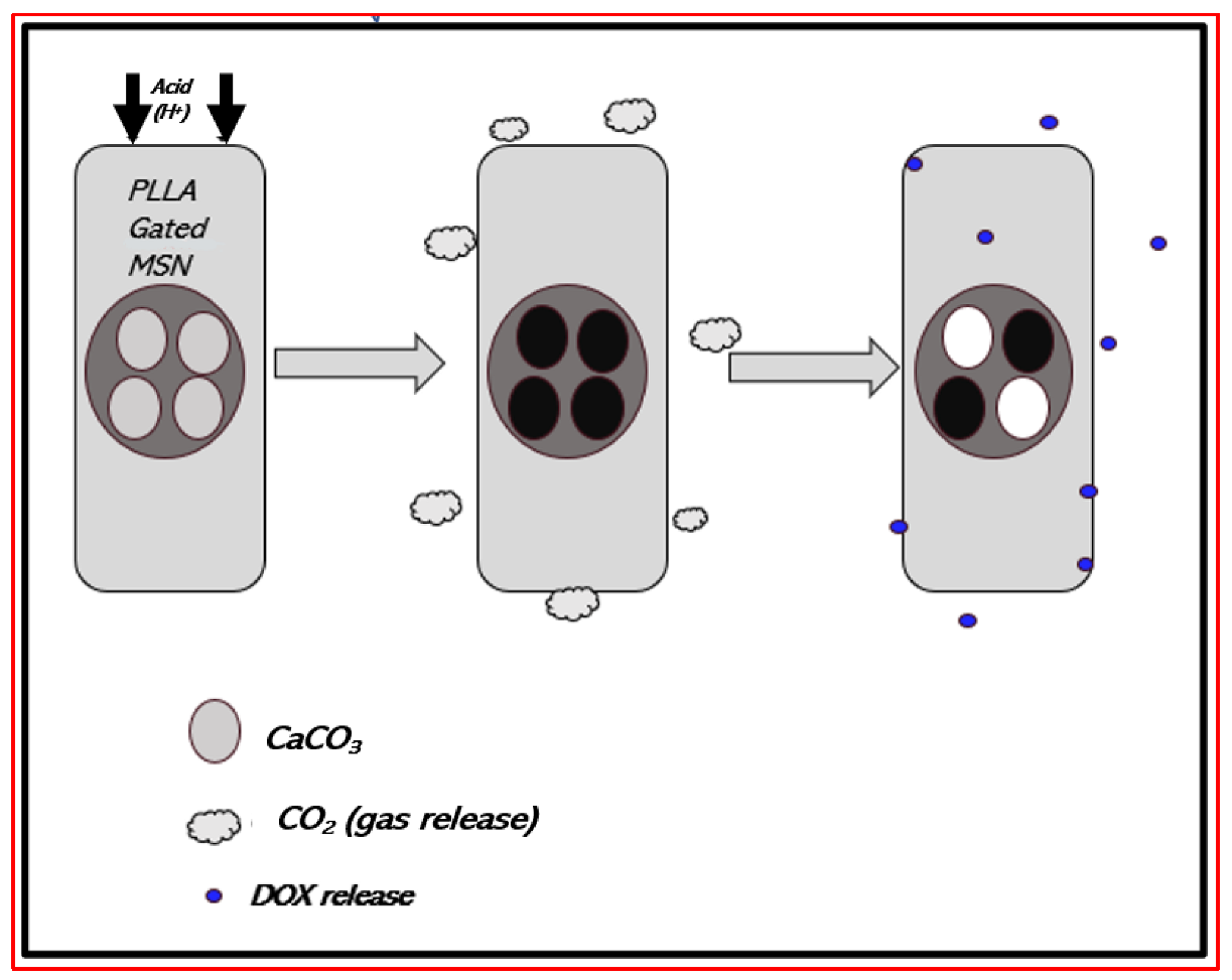
3.4.6. Drug Delivery

Electrospun fibers are great candidates for drug delivery. They possess a high specific surface area and can allow local drug delivery [61]. This method reduces drug toxicity and increases therapeutic efficacy by prolonging the dissolution of the drugs to achieve continuous drug release. It can be used to monitor cancer cell migration and locally control the release of anti-tumor drugs that can be loaded in the pores of fibers.
Different strategies can be employed.
First, the drug can be mixed in a polymer solution before electrospinning [61,152]. By loading an anticancer drug within the fibers, instability and adverse effects on surrounding healthy tissues are reduced, and the local concentration at the tumor site is increased [61]. Liu et al. developed doxorubicin hydrochloride loaded in electrospun PLLA nanofibers systems to treat liver cancer locally and prevent post-surgery metastasis. The drug was entirely diffused from the system [61,62]. Curcumin was incorporated into a PLLA/PHB solution before electrospinning. In vitro studies showed that it was released for 14 days and improved the osteogenic differentiation of human adipose-derived stem cells. In another study, an RNAi and polyethyleneimine plasmid (to specifically suppress matrix metalloproteinase-2 expression) and paclitaxel (a cytotoxic drug) were encapsulated in a PLGA nanofiber matrix to release both agents and thereby inhibit invasion, angiogenesis, growth, and cell proliferation [187].
The main issues for such an application are the release and degradation rates, which need to be deeply investigated in order to achieve controlled drug release (by diffusion or diffusion and degradation of the scaffold). To prevent an initial burst release, one strategy is to incorporate a nanocarrier into the fibers [61,152]. For example, Jonah et al. [188] generated a superhydrophobic electrospun nanofiber mesh to slow down the delivery of the encapsulated lipophilic anticancer agent, 7-ethyl-10-hydroxycamptothecin. In vitro results and results from an in vivo mouse model of lung cancer suggest that this system provides controlled and specific delivery to treat glioblastoma and prevent locoregional recurrence.
Drugs can also be chemically or physically immobilized on electrospun fiber surfaces [61]. Thus, immobilization prevents drug exposure to harsh solvents or to a high voltage that can denature or deactivate it. It also facilitates the process since, usually, drugs have high molecular weights and/or charges on their surfaces that make dissolution and electrospinning more difficult. To optimize drug immobilization, fiber surfaces are first treated chemically (addition of functional groups such as hydroxyl groups). Chemical functionalization allows the control of the amount of drug immobilized and reduces the initial burst release. Im et al. reduced the initial burst release by fluorinated crosslinked hydrogel fibers before adding the drug [61]. Also, a bandage was developed from electrospun PAN nanofibers, in which Munaweera et al. [189] incorporated holmium-166 to cure skin cancer without affecting healthy cells.
Another strategy is coaxial electrospinning. The polymer shell would then protect the core filled with biomolecules [61]. For example, nanogels sensible to redox reactions were incorporated into the outer shell of coaxial nanofibers containing BMP-2. When desulfated bonds of the nanogel were modified by the GSH concentration, BMP-2 was then released [190].
Also, for multidrug system delivery, stacked multilayer nanofibers can be produced. For example, Okuda et al. produced a tetra-layered nanofiber system for dual release: the first and third layers were drug-loaded, while the second and fourth were barrier meshes. They were able to realize timed dual release by modifying barrier meshes (such as thickness) [61].
Smart polymers enable on-demand drug delivery. For example, Kim et al. [191] electrospun a solution composed of chemically crosslinkable temperature-responsive polymers, magnetic nanoparticles, and doxorubicin to target skin cancer cells. When the nanofibers were exposed to a magnetic field, the nanoparticles produced heat that led to the deswelling of polymers and thus drug release. Also, lauric and stearic acids are phase-changing materials (PCMs) with a melting point of 39 °C [192]. Therefore, they can be used for controlled drug release by photothermal heating. Xue et al. [192] formed lipoproteins from these acids to encapsulate NGFs. These microparticles were then electrosprayed between two layers of electrospun PCL nanofibers. Nerve growth factors, released in a controlled manner, stimulated the PC12 growth of neurites into spheroids. Another strategy is to use pH stimulation. The cancer environment is known to have a rather acidic pH (6.8). Thus, Zhao et al. [193] produced PLA nanofibers containing drug-loaded silica nanoparticles functionalized with CaCO3 (Figure 15). When the environment was acidic, the physiological pH was reduced and CaCO3 dissolved, allowing drug release.
Finally, there is the possibility of electrospinning nanofibers for siRNA delivery to target specific cells [61]. Achille et al. [194] loaded a bioactive plasmid encoding shRNA against Cdk2 into nanofibers. When the fibers degraded, plasmid DNA was released over 21 days. This prevented MCF-7 proliferation and decreased their viability.

3.4.7. Wound Healing

To protect a wound, remove exudate, and inhibit microorganisms, dressings are necessary. Pores, large air surfaces, and the stimulation of fibroblast cells are the advantages of dressings made from electrospun nanofibers. Treatment factors, such as antibacterial factors, can be included in the matrix [45].
The introduction of natural extracts into nanofibers makes it possible to enhance wound reduction without synthetic compounds. Natural compounds, such as plant-based extracts or certain phytoconstituents (Curcumin, Lemongrass), as said before, promote wound healing in distinct stages of the process. They prevent coagulation and inflammation and induce re-epithelialization [155]. However, by only applying them to the wound, some inconveniences appear, such as drying or softening of the surrounding tissue. Consequently, introducing these components within an electrospun scaffold is a promising alternative [155]. Aloe Vera has antioxidant properties; induces the synthesis of collagen, hyaluronic acid, and dermatan sulfate, essential components of the ECM; and promotes cell proliferation and migration [147]. Garcia-Orue et al. incorporated Aloe Vera and epidermal growth factors into PLGA nanofibers [195]. Fibroblast proliferation was stimulated, and an in vivo study showed a significant increase in wound healing. Apitherapy is a potential target for wound healing as well. Honey/PVA/chitosan and propolis electrospun nanofibers possess antibacterial properties and promote wound healing. Another study on Waster rats highlights the effects of Garcinia mangostana acetone extract, added to chitosan and poly (vinyl alcohol) polymers before electrospinning. It inhibits microbial colonization but also enhances the wound-healing process [155].
Some polymers exhibit antibacterial properties. Among other materials, PAN nanofibers are one of them, and their physiological and mechanical properties make them promising candidates for wound healing. Antibacterial activity against S. aureus has been seen in Cu/PAN nanofibers, as well [45]. A patent filed in 2019 claims the antifungal activity of microfibers made from PAN nanofibers. These are sprayed onto a TEFLON® plate, air-dried, and then rinsed with acetone before being randomly stuck together in DMF [196]. Another example is presented in Ibrahim et al. works [197]. CMCS/PVA nanofibers containing gold nanoparticles (AuNPs) were prepared by electrospinning, and they showed higher antibacterial activity against Gram-negative and Gram-positive bacteria when encapsulated in nanofibers than when they were alone. They were noncytotoxic to A-549 cells. More recently, electrospun PCL-g-PAA nanofibers combined with GO-g-PTA nanosheets were studied for chronic wound care. The combination of the nanofibers absorbing body fluids and nanosheet antibacterial properties enhanced cell proliferation and the wound-healing process [198]. Quercetin is another natural compound presenting antioxidant, antiallergic, anticancer, antibacterial, and antifungal properties. It has been incorporated in electrospun PCL nanofibers and inhibited the formation of C. albicans biofilm [154].
Preventing scar formation is challenging, especially for deep-burn victims. To prevent it, molecules, such as inhibitors of transforming growth factor-β1, implicated in fibroblast proliferation deregulation, can be incorporated into nanofibers to reduce scar formation [199]. By promoting early wound healing with ginsenoside-Rg3 added to PLGA fibers, the formation of hypertrophic scars at an advanced stage was prevented, as well [200].
Diabetes might cause the impairment of repair mechanisms and the wound-healing process [201]. To help wound healing, the stimulation of collagen formation, re-epithelialization, vascularization, and the inhibition of inflammatory reactions can be promoted by controlling the release of dimethyloxalylglycine that was loaded in aligned PLA nanofibers, improving wound healing in patients with diabetes [98].
Angiogenesis is required for both maintaining the survival of the new tissue and its growth. Chen et al. produced a PCL nanofiber scaffold with B and Co co-doped bioactive glass nanoparticles. The scaffold was not cytotoxic to ST-2 bone marrow stromal cells, and their secretion of vascular endothelial growth factors was enhanced, thus increasing angiogenesis [202].
Finally, bifunctional matrices have shown great promise in healing tumor injury while preventing tumor recurrence. The addition of Cu2S to PLA and PCL nanofibers resulted in increased skin tumor cell mortality and tumor growth inhibition after photothermal heating while promoting the proliferation and migration of healthy skin cells to heal the wound [203].

3.4.8. Implant Coating

By coating implants with nanofibers, biocompatibility is improved, and there is a possibility of adding new biological signals. To improve the expansion range of a stent used to treat aneurysms, it was coated with PLCL nanofibers. Heparin and vascular endothelial growth factors were loaded in the nanofibers as well to prevent thrombus and induce endothelization [204].
Nanofibers can be used as a barrier to prevent post-surgical adhesion with surrounding tissues during repair, induce osteogenesis, and prevent bacterial infection [205]. PCL nanofibers, after undergoing cold plasma treatment, were functionalized with AMPS and used to cover a polypropylene mesh for hernia repair. This was implemented to avoid adhesions after intra-abdominal surgery thanks to anticoagulant and antiadhesive properties. These promising results on NIH3T3 cells need further studies in vivo [206]. PAN nanofibers, loaded with doped Ag nanoparticles, have been used to capture Escherichia coli. The negative charges of the silver particles allowed the immobilization of antibodies, helping to target specific pathogens by functionalizing the surface of the scaffold with anti-E. coli. Only E. coli was captured, and Staphylococcus aureus did not bind to it. Conversely, on a scaffold functionalized with anti-S. aureus, only S. Aureus was attached to the scaffold [205].

3.5. Combining Microfluidics and Electrospun Fiber Scaffold

Microfluidics allows the study of cell behavior by reproducing individual or combined physiological parameters. It ensures oxygen and nutrient distribution and waste removal by performing laminar flow to better mimic blood vessels. Different cell types can interact, and a gradient concentration can be applied through a coating or in solution. Combining both microfluidic technology and a 3D scaffold will greatly improve in vitro models in order to reduce cell culture artifacts, increase the possibilities of the in vitro mimicking of biological processes, and then reduce differences between preclinical and clinical studies [207]. Three different technologies have been developed to combine microfluidics and 3D electrospun scaffolds: lateral-flow models, electrospinning directly into a microfluidic channel, and integration of electrospun fibers. The lateral-flow model is a microfluidic device like paper-based microfluidics. However, the morphology and dimensions can be monitored, in contrast to paper. This technique is not suitable if shearing is applied. The second method is the direct electrospinning of the fibers inside the channel of the microfluidic device, but the channel must be at least 1 mm large. With the third method, fibers are first electrospun, then the scaffold is cut, and cells are seeded prior to insertion in a 3D-printed microfluidic device. This process appears to be the best suited, as the scaffold with cells seeded on it can be removed and studied, and the microfluidic device can be designed as desired.
Recently, Guida et al. introduced an electrospun PCL fiber scaffold in an open microfluidic chamber to study the differentiation of mammospheres derived from human mammary glands into luminal cells [208]. Microfluidics allowed the control of micro-environmental factors and of bioactive molecule exchanges, while nanofibers mimicked the ECM, providing support for differentiation, proliferation, and migration. Combining electrospinning and microfluidics shows great promise for in vitro studies, getting closer to the in vivo process.

4. Conclusions

In this review, we described how 3D scaffolds can be designed by electrospinning, which can be described as a nanofiber production method using electric forces. The theoretical aspects of the electrospinning process were detailed. Multi-needle electrospinning, which is an approach proposed for scaling up from the laboratory to the production scale, has been presented. Electrospun scaffolds are used in many fields, such as protection, the production of electrode materials and sensors, filtration, data storage and transport in informatics, textile production, adsorption, the decomposition of pollutants, and biomedical applications. We reviewed the possible applications involving electrospun fibers in different domains of medicine and biotechnologies. Among the materials used for electrospinning, PAN is the main carbon fiber precursor since it has a high melting point and a great carbon yield. Fibers possess good resistance, low density, and high stiffness; are lightweight; have amazing biocompatibility properties; and allow the possible use of low-toxicity solvents. However, electrospun PAN nanofibers are not yet widespread for the production of scaffolds employed for cell culture and biological studies. We provided bibliographic data on the way that PAN could be electrospun into fibers and presented the subsequent treatments prior to their application. The applications of exPAN fibers in the biomedical field were described, and we showed how 3D scaffolds are particularly attractive for cell growth. The possibility of tuning the mechanical properties of the scaffold independently of other parameters offers new opportunities in research, aiming to understand mechanosensing processes in a 3D environment and their effects on cellular behavior. Therefore, 3D nanofiber scaffolds represent promising materials for future developments in drug screening, cell therapy, and bioproduction as a biomimicking and highly controllable in vitro microenvironment.

Author Contributions

Conceptualization, B.F.; validation, J.C., D.C., N.B. and E.M.; writing—original draft preparation, B.F. and B.L.; writing—review and editing, B.F.; supervision, J.C. and D.C.; All authors have read and agreed to the published version of the manuscript.

Funding

This research received no external funding.

Institutional Review Board Statement

Not applicable.

Informed Consent Statement

Not applicable.

Data Availability Statement

The data presented in this study are available on request from the corresponding author.

Conflicts of Interest

The authors declare no conflict of interest.

References

  1. Cherry, R.H. History of Sericulture. Bull. Entomol. Soc. Am. 1987, 33, 83–85. [Google Scholar] [CrossRef]
  2. Vollrath, F.; Knight, D.P. Liquid Crystalline Spinning of Spider Silk. Nature 2001, 410, 541–548. [Google Scholar] [CrossRef] [PubMed]
  3. Heim, M.; Keerl, D.; Scheibel, T. Spider Silk: From Soluble Protein to Extraordinary Fiber. Angew. Chem. Int. Ed. 2009, 48, 3584–3596. [Google Scholar] [CrossRef] [PubMed]
  4. Thyavihalli Girijappa, Y.G.; Mavinkere Rangappa, S.; Parameswaranpillai, J.; Siengchin, S. Natural Fibers as Sustainable and Renewable Resource for Development of Eco-Friendly Composites: A Comprehensive Review. Front. Mater. 2019, 6, 226. [Google Scholar] [CrossRef]
  5. Thenmozhi, S.; Dharmaraj, N.; Kadirvelu, K.; Kim, H.Y. Electrospun Nanofibers: New Generation Materials for Advanced Applications. Mater. Sci. Eng. B 2017, 217, 36–48. [Google Scholar] [CrossRef]
  6. Ramakrishna, S.; Fujihara, K.; Teo, W.-E.; Yong, T.; Ma, Z.; Ramaseshan, R. Electrospun Nanofibers: Solving Global Issues. Mater. Today 2006, 9, 40–50. [Google Scholar] [CrossRef]
  7. Liu, Q.; Zhu, J.; Zhang, L.; Qiu, Y. Recent Advances in Energy Materials by Electrospinning. Renew. Sustain. Energy Rev. 2018, 81, 1825–1858. [Google Scholar] [CrossRef]
  8. Hu, X.; Liu, S.; Zhou, G.; Huang, Y.; Xie, Z.; Jing, X. Electrospinning of Polymeric Nanofibers for Drug Delivery Applications. J. Control. Release 2014, 185, 12–21. [Google Scholar] [CrossRef]
  9. Luo, C.J.; Stoyanov, S.D.; Stride, E.; Pelan, E.; Edirisinghe, M. Electrospinning versus Fibre Production Methods: From Specifics to Technological Convergence. Chem. Soc. Rev. 2012, 41, 4708. [Google Scholar] [CrossRef]
  10. Cooley, J.F. Apparatus for Electrically Dispersing Fluids. U.S. Patent 692,631, 4 February 1902. [Google Scholar]
  11. Von Bailey, A.G. Electrostatic Spraying of Liquids. Research Studies Press LTD: Taunton, Somerset/John Wiley & Sons Inc, New York 1988; 197 Seiten, 24,75$. Phys. Unserer Zeit. 1989, 20, 160. [Google Scholar] [CrossRef]
  12. Sirelkhatim, N.; LaJeunesse, D.; Kelkar, A.D.; Zhang, L. Antifungal Activity of Amidoxime Surface Functionalized Electrospun Polyacrylonitrile Nanofibers. Mater. Lett. 2015, 141, 217–220. [Google Scholar] [CrossRef]
  13. Wehlage, D.; Blattner, H.; Mamun, A.; Kutzli, I.; Diestelhorst, E.; Rattenholl, A.; Gudermann, F.; Lütkemeyer, D.; Ehrmann, A. Cell Growth on Electrospun Nanofiber Mats from Polyacrylonitrile (PAN) Blends. AIMS Bioeng. 2020, 7, 43–54. [Google Scholar] [CrossRef]
  14. Sabantina, L.; Kinzel, F.; Hauser, T.; Többer, A.; Klöcker, M.; Döpke, C.; Böttjer, R.; Wehlage, D.; Rattenholl, A.; Ehrmann, A. Comparative Study of Pleurotus Ostreatus Mushroom Grown on Modified PAN Nanofiber Mats. Nanomaterials 2019, 9, 475. [Google Scholar] [CrossRef] [PubMed]
  15. Liu, Y.; Zhang, L.; Sun, X.-F.; Liu, J.; Fan, J.; Huang, D.-W. Multi-Jet Electrospinning via Auxiliary Electrode. Mater. Lett. 2015, 141, 153–156. [Google Scholar] [CrossRef]
  16. Yan, T.; Tian, L.; Pan, Z. Structures and Mechanical Properties of Plied and Twisted Polyacrylonitrile Nanofiber Yarns Fabricated by a Multi-Needle Electrospinning Device. Fibers Polym. 2016, 17, 1627–1633. [Google Scholar] [CrossRef]
  17. SalehHudin, H.S.; Mohamad, E.N.; Mahadi, W.N.L.; Muhammad Afifi, A. Multiple-Jet Electrospinning Methods for Nanofiber Processing: A Review. Mater. Manuf. Process. 2018, 33, 479–498. [Google Scholar] [CrossRef]
  18. Gao, H.; Yang, Y.; Akampumuza, O.; Hou, J.; Zhang, H.; Qin, X. A Low Filtration Resistance Three-Dimensional Composite Membrane Fabricated via Free Surface Electrospinning for Effective PM2.5 Capture. Environ. Sci. Nano 2017, 4, 864–875. [Google Scholar] [CrossRef]
  19. Marhuenda, E.; Fabre, C.; Zhang, C.; Martin-Fernandez, M.; Iskratsch, T.; Saleh, A.; Bauchet, L.; Cambedouzou, J.; Hugnot, J.-P.; Duffau, H.; et al. Glioma Stem Cells Invasive Phenotype at Optimal Stiffness Is Driven by MGAT5 Dependent Mechanosensing. J. Exp. Clin. Cancer Res. 2021, 40, 139. [Google Scholar] [CrossRef]
  20. Yusof, N.; Ismail, A.F. Post Spinning and Pyrolysis Processes of Polyacrylonitrile (PAN)-Based Carbon Fiber and Activated Carbon Fiber: A Review. J. Anal. Appl. Pyrolysis 2012, 93, 1–13. [Google Scholar] [CrossRef]
  21. Hameed, N.; Sharp, J.; Nunna, S.; Creighton, C.; Magniez, K.; Jyotishkumar, P.; Salim, N.V.; Fox, B. Structural Transformation of Polyacrylonitrile Fibers during Stabilization and Low Temperature Carbonization. Polym. Degrad. Stab. 2016, 128, 39–45. [Google Scholar] [CrossRef]
  22. Chen, L.; Shen, Z.; Liu, J.; Liang, J.; Wang, X. Effects of Oxygen on the Structural Evolution of Polyacrylonitrile Fibers during Rapid Thermal Treatment. RSC Adv. 2020, 10, 6356–6361. [Google Scholar] [CrossRef] [PubMed]
  23. Park, D.U.; Han, N.K.; Ryu, J.H.; Park, W.H.; Jeong, Y.G. Spectroscopic Analyses on Chain Structure and Thermal Stabilization Behavior of Acrylonitrile/Methyl Acrylate/Itaconic Acid-Based Copolymers Synthesized by Aqueous Suspension Polymerization. Fibers Polym. 2018, 19, 2007–2015. [Google Scholar] [CrossRef]
  24. Dang, W.; Liu, J.; Wang, X.; Yan, K.; Zhang, A.; Yang, J.; Chen, L.; Liang, J. Structural Transformation of Polyacrylonitrile (PAN) Fibers during Rapid Thermal Pretreatment in Nitrogen Atmosphere. Polymers 2020, 12, 63. [Google Scholar] [CrossRef] [PubMed]
  25. Xue, J.; Wu, T.; Dai, Y.; Xia, Y. Electrospinning and Electrospun Nanofibers: Methods, Materials, and Applications. Chem. Rev. 2019, 119, 5298–5415. [Google Scholar] [CrossRef] [PubMed]
  26. Haider, A.; Haider, S.; Kang, I.-K. A Comprehensive Review Summarizing the Effect of Electrospinning Parameters and Potential Applications of Nanofibers in Biomedical and Biotechnology. Arab. J. Chem. 2018, 11, 1165–1188. [Google Scholar] [CrossRef]
  27. Zhou, F.-L.; Gong, R.-H.; Porat, I. Mass Production of Nanofibre Assemblies by Electrostatic Spinning. Polym. Int. 2009, 58, 331–342. [Google Scholar] [CrossRef]
  28. Park, C.H.; Pant, H.R.; Kim, C.S. Novel Robot-Assisted Angled Multi-Nozzle Electrospinning Set-Up: Computer Simulation with Experimental Observation of Electric Field and Fiber Morphology. Text. Res. J. 2014, 84, 1044–1058. [Google Scholar] [CrossRef]
  29. Reneker, D.H.; Yarin, A.L. Electrospinning Jets and Polymer Nanofibers. Polymer 2008, 49, 2387–2425. [Google Scholar] [CrossRef]
  30. He, J.-H.; Wu, Y.; Zuo, W.-W. Critical Length of Straight Jet in Electrospinning. Polymer 2005, 46, 12637–12640. [Google Scholar] [CrossRef]
  31. Collins, G.; Federici, J.; Imura, Y.; Catalani, L.H. Charge Generation, Charge Transport, and Residual Charge in the Electrospinning of Polymers: A Review of Issues and Complications. J. Appl. Phys. 2012, 111, 044701. [Google Scholar] [CrossRef]
  32. Song, Z.; Chiang, S.W.; Chu, X.; Du, H.; Li, J.; Gan, L.; Xu, C.; Yao, Y.; He, Y.; Li, B.; et al. Effects of Solvent on Structures and Properties of Electrospun Poly(Ethylene Oxide) Nanofibers: ARTICLE. J. Appl. Polym. Sci. 2018, 135, 45787. [Google Scholar] [CrossRef]
  33. Son, W.K.; Youk, J.H.; Lee, T.S.; Park, W.H. The Effects of Solution Properties and Polyelectrolyte on Electrospinning of Ultrafine Poly(Ethylene Oxide) Fibers. Polymer 2004, 45, 2959–2966. [Google Scholar] [CrossRef]
  34. Hekmati, A.H.; Rashidi, A.; Ghazisaeidi, R.; Drean, J.-Y. Effect of Needle Length, Electrospinning Distance, and Solution Concentration on Morphological Properties of Polyamide-6 Electrospun Nanowebs. Text. Res. J. 2013, 83, 1452–1466. [Google Scholar] [CrossRef]
  35. Xiao, S.; Shen, M.; Ma, H.; Guo, R.; Zhu, M.; Wang, S.; Shi, X. Fabrication of Water-Stable Electrospun Polyacrylic Acid-Based Nanofibrous Mats for Removal of Copper (II) Ions in Aqueous Solution. J. Appl. Polym. Sci. 2010, 116, 2409–2417. [Google Scholar] [CrossRef]
  36. Zhang, C.; Yuan, X.; Wu, L.; Han, Y.; Sheng, J. Study on Morphology of Electrospun Poly(Vinyl Alcohol) Mats. Eur. Polym. J. 2005, 41, 423–432. [Google Scholar] [CrossRef]
  37. Jacobs, V.; Anandjiwala, R.D.; Maaza, M. The Influence of Electrospinning Parameters on the Structural Morphology and Diameter of Electrospun Nanofibers. J. Appl. Polym. Sci. 2010, 115, 3130–3136. [Google Scholar] [CrossRef]
  38. Zhu, Z.; Wu, P.; Wang, Z.; Xu, G.; Wang, H.; Chen, X.; Wang, R.; Huang, W.; Chen, R.; Chen, X.; et al. Optimization of Electric Field Uniformity of Multi-Needle Electrospinning Nozzle. AIP Adv. 2019, 9, 105104. [Google Scholar] [CrossRef]
  39. Tomaszewski, W.; Szadkowski, M. Investigation of Electrospinning with the Use of a Multi-Jet Electrospinning Head. Fibres Text. East. Eur. 2005, 13, 22. [Google Scholar]
  40. Yang, Y.; Jia, Z.; Li, Q.; Hou, L.; Guan, Z. Electrospun Uniform Fibres with a Special Regular Hexagon Distributed Multi-Needles System. J. Phys. Conf. Ser. 2008, 142, 012027. [Google Scholar] [CrossRef]
  41. Theron, S.A.; Yarin, A.L.; Zussman, E.; Kroll, E. Multiple Jets in Electrospinning: Experiment and Modeling. Polymer 2005, 46, 2889–2899. [Google Scholar] [CrossRef]
  42. Yang, Y.; Jia, Z.; Li, Q.; Hou, L.; Liu, J.; Wang, L.; Guan, Z.; Zahn, M. A Shield Ring Enhanced Equilateral Hexagon Distributed Multi-Needle Electrospinning Spinneret. IEEE Trans. Dielect. Electr. Insul. 2010, 17, 1592–1601. [Google Scholar] [CrossRef]
  43. Zheng, Y.; Gong, R.H.; Zeng, Y. Multijet Motion and Deviation in Electrospinning. RSC Adv. 2015, 5, 48533–48540. [Google Scholar] [CrossRef]
  44. Omer, S.; Forgách, L.; Zelkó, R.; Sebe, I. Scale-up of Electrospinning: Market Overview of Products and Devices for Pharmaceutical and Biomedical Purposes. Pharmaceutics 2021, 13, 286. [Google Scholar] [CrossRef] [PubMed]
  45. Kapałczyńska, M.; Kolenda, T.; Przybyła, W.; Zajączkowska, M.; Teresiak, A.; Filas, V.; Ibbs, M.; Bliźniak, R.; Łuczewski, Ł.; Lamperska, K. 2D and 3D Cell Cultures—A Comparison of Different Types of Cancer Cell Cultures. Arch. Med. Sci. 2018, 14, 910–919. [Google Scholar] [CrossRef]
  46. Sośniak, J.; Opiela, J. 3D Cell Culture Technology—A New Insight Into in Vitro Research—A Review. Ann. Anim. Sci. 2021, 21, 1257–1273. [Google Scholar] [CrossRef]
  47. Saleh, A.; Marhuenda, E.; Fabre, C.; Hassani, Z.; de Weille, J.; Boukhaddaoui, H.; Guelfi, S.; Maldonado, I.L.; Hugnot, J.-P.; Duffau, H.; et al. A Novel 3D Nanofibre Scaffold Conserves the Plasticity of Glioblastoma Stem Cell Invasion by Regulating Galectin-3 and Integrin-Β1 Expression. Sci. Rep. 2019, 9, 14612. [Google Scholar] [CrossRef] [PubMed]
  48. Kasper, C.; Egger, D.; Lavrentieva, A. (Eds.) Basic Concepts on 3D Cell Culture; Learning Materials in Biosciences; Springer International Publishing: Cham, Switzerland, 2021; ISBN 978-3-030-66748-1. [Google Scholar]
  49. Suh, T.C.; Amanah, A.Y.; Gluck, J.M. Electrospun Scaffolds and Induced Pluripotent Stem Cell-Derived Cardiomyocytes for Cardiac Tissue Engineering Applications. Bioengineering 2020, 7, 105. [Google Scholar] [CrossRef] [PubMed]
  50. Duval, K.; Grover, H.; Han, L.-H.; Mou, Y.; Pegoraro, A.F.; Fredberg, J.; Chen, Z. Modeling Physiological Events in 2D vs. 3D Cell Culture. Physiology 2017, 32, 266–277. [Google Scholar] [CrossRef]
  51. Shologu, N.; Szegezdi, E.; Lowery, A.; Kerin, M.; Pandit, A.; Zeugolis, D.I. Recreating Complex Pathophysiologies in Vitro with Extracellular Matrix Surrogates for Anticancer Therapeutics Screening. Drug Discov. Today 2016, 21, 1521–1531. [Google Scholar] [CrossRef]
  52. Snetkov, P.; Zakharova, K.; Morozkina, S.; Olekhnovich, R.; Uspenskaya, M. Hyaluronic Acid: The Influence of Molecular Weight on Structural, Physical, Physico-Chemical, and Degradable Properties of Biopolymer. Polymers 2020, 12, 1800. [Google Scholar] [CrossRef]
  53. Habanjar, O.; Diab-Assaf, M.; Caldefie-Chezet, F.; Delort, L. 3D Cell Culture Systems: Tumor Application, Advantages, and Disadvantages. IJMS 2021, 22, 12200. [Google Scholar] [CrossRef]
  54. Nikolova, M.P.; Chavali, M.S. Recent Advances in Biomaterials for 3D Scaffolds: A Review. Bioact. Mater. 2019, 4, 271–292. [Google Scholar] [CrossRef] [PubMed]
  55. Qu, H.; Fu, H.; Han, Z.; Sun, Y. Biomaterials for Bone Tissue Engineering Scaffolds: A Review. RSC Adv. 2019, 9, 26252–26262. [Google Scholar] [CrossRef] [PubMed]
  56. Liu, Z.; Ramakrishna, S.; Liu, X. Electrospinning and Emerging Healthcare and Medicine Possibilities. APL Bioeng. 2020, 4, 030901. [Google Scholar] [CrossRef] [PubMed]
  57. Yu, X.; Tang, X.; Gohil, S.V.; Laurencin, C.T. Biomaterials for Bone Regenerative Engineering. Adv. Healthc. Mater. 2015, 4, 1268–1285. [Google Scholar] [CrossRef] [PubMed]
  58. Marchini, A.; Gelain, F. Synthetic Scaffolds for 3D Cell Cultures and Organoids: Applications in Regenerative Medicine. Crit. Rev. Biotechnol. 2021, 42, 468–486. [Google Scholar] [CrossRef] [PubMed]
  59. Clevers, H. Modeling Development and Disease with Organoids. Cell 2016, 165, 1586–1597. [Google Scholar] [CrossRef] [PubMed]
  60. Nemati, S.; Kim, S.; Shin, Y.M.; Shin, H. Current Progress in Application of Polymeric Nanofibers to Tissue Engineering. Nano Converg. 2019, 6, 36. [Google Scholar] [CrossRef] [PubMed]
  61. Cavo, M.; Serio, F.; Kale, N.R.; D’Amone, E.; Gigli, G.; del Mercato, L.L. Electrospun Nanofibers in Cancer Research: From Engineering of in Vitro 3D Cancer Models to Therapy. Biomater. Sci. 2020, 8, 4887–4905. [Google Scholar] [CrossRef]
  62. Abazari, M.F.; Zare Karizi, S.; Hajati-Birgani, N.; Kohandani, M.; Torabinejad, S.; Nejati, F.; Nasiri, N.; Maleki, M.H.; Mohajerani, H.; Mansouri, V. Curcumin-loaded PHB/PLLA Nanofibrous Scaffold Supports Osteogenesis in Adipose-derived Stem Cells in Vitro. Polym. Adv. Technol. 2021, 32, 3563–3571. [Google Scholar] [CrossRef]
  63. Larrondo, L.; St. John Manley, R. Electrostatic Fiber Spinning from Polymer Melts. I. Experimental Observations on Fiber Formation and Properties. J. Polym. Sci. Polym. Phys. Ed. 1981, 19, 909–920. [Google Scholar] [CrossRef]
  64. Agrawal, P.; Pramanik, K. Chitosan-Poly(Vinyl Alcohol) Nanofibers by Free Surface Electrospinning for Tissue Engineering Applications. Tissue Eng. Regen. Med. 2016, 13, 485–497. [Google Scholar] [CrossRef] [PubMed]
  65. Dai, Y.; Liu, W.; Formo, E.; Sun, Y.; Xia, Y. Ceramic Nanofibers Fabricated by Electrospinning and Their Applications in Catalysis, Environmental Science, and Energy Technology: Ceramic Nanofibers Fabricated by Electrospinning and Their Applications. Polym. Adv. Technol. 2011, 22, 326–338. [Google Scholar] [CrossRef]
  66. He, D.; Hu, B.; Yao, Q.-F.; Wang, K.; Yu, S.-H. Large-Scale Synthesis of Flexible Free-Standing SERS Substrates with High Sensitivity: Electrospun PVA Nanofibers Embedded with Controlled Alignment of Silver Nanoparticles. ACS Nano 2009, 3, 3993–4002. [Google Scholar] [CrossRef]
  67. Rahaman, M.S.A.; Ismail, A.F.; Mustafa, A. A Review of Heat Treatment on Polyacrylonitrile Fiber. Polym. Degrad. Stab. 2007, 92, 1421–1432. [Google Scholar] [CrossRef]
  68. Eren, O.; Ucar, N.; Onen, A.; Karacan, I.; Kizildag, N.; Demirsoy, N.; Vurur, O.F.; Borazan, I. Effect of Differently Functionalized Carbon Nanotubes on the Properties of Composite Nanofibres. Indian J. Fibre Text. Tes. 2016, 41, 138–144. [Google Scholar]
  69. Ruiz, A.; Vega, E.; Katiyar, R.; Valentin, R. Functionalized Nanowires from Electrospun Polymer Nanofibers. Nanotechnol. III 2007, 6591, 659106. [Google Scholar]
  70. Engel, A.B.; Bechelany, M.; Fontaine, O.; Cherifi, A.; Cornu, D.; Tingry, S. One-Pot Route to Gold Nanoparticles Embedded in Electrospun Carbon Fibers as an Efficient Catalyst Material for Hybrid Alkaline Glucose Biofuel Cells. ChemElectroChem 2016, 3, 629–637. [Google Scholar] [CrossRef]
  71. Wahab, J.A.; Mamun, S.A. Polyacrylonitrile Nanofiber Mats Containing Titania/AgNP Composite Nanoparticles for Antibacterial Applications. Mater. Res. Express 2020, 7, 015416. [Google Scholar] [CrossRef]
  72. Patel, S.; Konar, M.; Sahoo, H.; Hota, G. Surface Functionalization of Electrospun PAN Nanofibers with ZnO–Ag Heterostructure Nanoparticles: Synthesis and Antibacterial Study. Nanotechnology 2019, 30, 205704. [Google Scholar] [CrossRef]
  73. Zhang, L.; Luo, J.; Menkhaus, T.J.; Varadaraju, H.; Sun, Y.; Fong, H. Antimicrobial Nano-Fibrous Membranes Developed from Electrospun Polyacrylonitrile Nanofibers. J. Membr. Sci. 2011, 369, 499–505. [Google Scholar] [CrossRef]
  74. Grothe, T.; Storck, J.L.; Dotter, M.; Ehrmann, A. Impact of Solid Content in the Electrospinning Solution on the Physical and Chemical Properties of Polyacrylonitrile (PAN) Nanofibrous Mats. Tekstilec 2020, 63, 225–232. [Google Scholar] [CrossRef]
  75. Gu, S.Y.; Ren, J.; Vancso, G.J. Process Optimization and Empirical Modeling for Electrospun Polyacrylonitrile (PAN) Nanofiber Precursor of Carbon Nanofibers. Eur. Polym. J. 2005, 41, 2559–2568. [Google Scholar] [CrossRef]
  76. Fu, Z.; Liu, B.; Sun, L.; Zhang, H. Study on the Thermal Oxidative Stabilization Reactions and the Formed Structures in Polyacrylonitrile during Thermal Treatment. Polym. Degrad. Stab. 2017, 140, 104–113. [Google Scholar] [CrossRef]
  77. Khayyam, H.; Jazar, R.N.; Nunna, S.; Golkarnarenji, G.; Badii, K.; Fakhrhoseini, S.M.; Kumar, S.; Naebe, M. PAN Precursor Fabrication, Applications and Thermal Stabilization Process in Carbon Fiber Production: Experimental and Mathematical Modelling. Prog. Mater. Sci. 2020, 107, 100575. [Google Scholar] [CrossRef]
  78. Burlant, W.J.; Parsons, J.L. Pyrolysis of Polyacrylonitrile. J. Polym. Sci. 1956, 22, 249–256. [Google Scholar] [CrossRef]
  79. Zhao, R.; Zhao, X.; Gao, Z.; Liu, X.; Che, X. Influence of Thermal Temperature on the Structure and Sealed Micropores of Stabilized Polyacrylonitrile Fibers. Chem. Res. Chin. Univ. 2017, 33, 312–317. [Google Scholar] [CrossRef]
  80. Gergin, İ.; Ismar, E.; Sarac, A.S. Oxidative Stabilization of Polyacrylonitrile Nanofibers and Carbon Nanofibers Containing Graphene Oxide (GO): A Spectroscopic and Electrochemical Study. Beilstein J. Nanotechnol. 2017, 8, 1616–1628. [Google Scholar] [CrossRef]
  81. Lee, S.; Kim, J.; Ku, B.-C.; Kim, J.; Joh, H.-I. Structural Evolution of Polyacrylonitrile Fibers in Stabilization and Carbonization. ACES 2012, 2, 275–282. [Google Scholar] [CrossRef]
  82. Khanderi, J.; Schneider, J.J. Polyacrylonitrile-Derived 1D Carbon Structures via Template Wetting and Electrospinning. Z. Anorg. Allg. Chem. 2009, 635, 2135–2142. [Google Scholar] [CrossRef]
  83. Kim, J.; Kim, Y.C.; Ahn, W.; Kim, C.Y. Reaction Mechanisms of Polyacrylonitrile on Thermal Treatment. Polym. Eng. Sci. 1993, 33, 1452–1457. [Google Scholar] [CrossRef]
  84. Fitzer, E.; Müller, D.J. The Influence of Oxygen on the Chemical Reactions during Stabilization of Pan as Carbon Fiber Precursor. Carbon 1975, 13, 63–69. [Google Scholar] [CrossRef]
  85. Xue, T.J.; McKinney, M.A.; Wilkie, C.A. The Thermal Degradation of Polyacrylonitrile—ScienceDirect. Available online: https://www-sciencedirect-com.inc.bib.cnrs.fr/science/article/pii/S0141391097000487?via%3Dihub (accessed on 14 September 2021).
  86. Alarifi, I.M.; Khan, W.S.; Asmatulu, R. Synthesis of Electrospun Polyacrylonitrile- Derived Carbon Fibers and Comparison of Properties with Bulk Form. PLoS ONE 2018, 13, e0201345. [Google Scholar] [CrossRef] [PubMed]
  87. Yu, M.-J.; Wang, C.-G.; Bai, Y.-J.; Xu, Y.; Zhu, B. Effect of Oxygen Uptake and Aromatization on the Skin–Core Morphology during the Oxidative Stabilization of Polyacrylonitrile Fibers. J. Appl. Polym. Sci. 2008, 107, 1939–1945. [Google Scholar] [CrossRef]
  88. Truong, Y.B.; Glattauer, V.; Briggs, K.L.; Zappe, S.; Ramshaw, J.A.M. Collagen-Based Layer-by-Layer Coating on Electrospun Polymer Scaffolds. Biomaterials 2012, 33, 9198–9204. [Google Scholar] [CrossRef] [PubMed]
  89. Yıldız, A.; Kara, A.A.; Acartürk, F. Peptide-Protein Based Nanofibers in Pharmaceutical and Biomedical Applications. Int. J. Biol. Macromol. 2020, 148, 1084–1097. [Google Scholar] [CrossRef]
  90. Kohn, S.; Wehlage, D.; Juhász Junger, I.; Ehrmann, A. Electrospinning a Dye-Sensitized Solar Cell. Catalysts 2019, 9, 975. [Google Scholar] [CrossRef]
  91. How Is the Organization and Function of the Genome Regulated?|MBInfo. Available online: https://www.mechanobio.info/avada_faq/what-is-genome-regulation-2/ (accessed on 7 February 2022).
  92. Cho, A.-N.; Jin, Y.; Kim, S.; Kumar, S.; Shin, H.; Kang, H.-C.; Cho, S.-W. Aligned Brain Extracellular Matrix Promotes Differentiation and Myelination of Human-Induced Pluripotent Stem Cell-Derived Oligodendrocytes. ACS Appl. Mater. Interfaces 2019, 11, 15344–15353. [Google Scholar] [CrossRef]
  93. Park, S.-H. Creation of a Hybrid Scaffold with Dual Configuration of Aligned and Random Electrospun Fibers. ACS Appl. Mater. 2016, 8, 2826–2832. [Google Scholar] [CrossRef]
  94. Lin, C.-C.; Fu, S.-J. Osteogenesis of Human Adipose-Derived Stem Cells on Poly(Dopamine)-Coated Electrospun Poly(Lactic Acid) Fiber Mats. Mater. Sci. Eng. C 2016, 58, 254–263. [Google Scholar] [CrossRef]
  95. Nedjari, S.; Hébraud, A.; Eap, S.; Siegwald, S.; Mélart, C.; Benkirane-Jessel, N.; Schlatter, G. Electrostatic Template-Assisted Deposition of Microparticles on Electrospun Nanofibers: Towards Microstructured Functional Biochips for Screening Applications. RSC Adv. 2015, 5, 83600–83607. [Google Scholar] [CrossRef]
  96. Kador, K.E.; Alsehli, H.S.; Zindell, A.N.; Lau, L.W.; Andreopoulos, F.M.; Watson, B.D.; Goldberg, J.L. Retinal Ganglion Cell Polarization Using Immobilized Guidance Cues on a Tissue-Engineered Scaffold. Acta Biomater. 2014, 10, 4939–4946. [Google Scholar] [CrossRef]
  97. Metwally, S.; Ferraris, S.; Spriano, S.; Krysiak, Z.J.; Kaniuk, Ł.; Marzec, M.M.; Kim, S.K.; Szewczyk, P.K.; Gruszczyński, A.; Wytrwal-Sarna, M.; et al. Surface Potential and Roughness Controlled Cell Adhesion and Collagen Formation in Electrospun PCL Fibers for Bone Regeneration. Mater. Des. 2020, 194, 108915. [Google Scholar] [CrossRef]
  98. Ren, X.; Han, Y.; Wang, J.; Jiang, Y.; Yi, Z.; Xu, H.; Ke, Q. An Aligned Porous Electrospun Fibrous Membrane with Controlled Drug Delivery—An Efficient Strategy to Accelerate Diabetic Wound Healing with Improved Angiogenesis. Acta Biomater. 2018, 70, 140–153. [Google Scholar] [CrossRef] [PubMed]
  99. Ibrahim, H.M.; Klingner, A. A Review on Electrospun Polymeric Nanofibers: Production Parameters and Potential Applications. Polym. Test. 2020, 90, 106647. [Google Scholar] [CrossRef]
  100. Xie, J.; Shen, H.; Yuan, G.; Lin, K.; Su, J. The Effects of Alignment and Diameter of Electrospun Fibers on the Cellular Behaviors and Osteogenesis of BMSCs. Mater. Sci. Eng. C 2021, 120, 111787. [Google Scholar] [CrossRef] [PubMed]
  101. Han, D.G.; Ahn, C.B.; Lee, J.-H.; Hwang, Y.; Kim, J.H.; Park, K.Y.; Lee, J.W.; Son, K.H. Optimization of Electrospun Poly(Caprolactone) Fiber Diameter for Vascular Scaffolds to Maximize Smooth Muscle Cell Infiltration and Phenotype Modulation. Polymers 2019, 11, 643. [Google Scholar] [CrossRef] [PubMed]
  102. Casper, C.L.; Stephens, J.S.; Tassi, N.G.; Chase, D.B.; Rabolt, J.F. Controlling Surface Morphology of Electrospun Polystyrene Fibers: Effect of Humidity and Molecular Weight in the Electrospinning Process. Macromolecules 2004, 37, 573–578. [Google Scholar] [CrossRef]
  103. Megelski, S.; Stephens, J.S.; Chase, D.B.; Rabolt, J.F. Micro- and Nanostructured Surface Morphology on Electrospun Polymer Fibers. Macromolecules 2002, 35, 8456–8466. [Google Scholar] [CrossRef]
  104. McCann, J.T. Highly Porous Fibers by Electrospinning into a Cryogenic Liquid—PDF Free Download. Available online: https://docecity.com/highly-porous-fibers-by-electrospinning-into-a-cryogenic-liq-5f101e4ba5206.html (accessed on 27 January 2022).
  105. Nayani, K.; Katepalli, H.; Sharma, C.S.; Sharma, A.; Patil, S.; Venkataraghavan, R. Electrospinning Combined with Nonsolvent-Induced Phase Separation To Fabricate Highly Porous and Hollow Submicrometer Polymer Fibers. Ind. Eng. Chem. Res. 2012, 51, 1761–1766. [Google Scholar] [CrossRef]
  106. Wu, J.; Hong, Y. Enhancing Cell Infiltration of Electrospun Fibrous Scaffolds in Tissue Regeneration. Bioact. Mater. 2016, 1, 56–64. [Google Scholar] [CrossRef]
  107. Li, D.; Xia, Y. Direct Fabrication of Composite and Ceramic Hollow Nanofibers by Electrospinning. Nano Lett. 2004, 4, 933–938. [Google Scholar] [CrossRef]
  108. Sadeghi-avalshahr, A.R.; Nokhasteh, S.; Molavi, A.M.; Mohammad-pour, N.; Sadeghi, M. Tailored PCL Scaffolds as Skin Substitutes Using Sacrificial PVP Fibers and Collagen/Chitosan Blends. IJMS 2020, 21, 2311. [Google Scholar] [CrossRef] [PubMed]
  109. Nam, J.; Huang, Y.; Agarwal, S.; Lannutti, J. Improved Cellular Infiltration in Electrospun Fiber via Engineered Porosity. Tissue Eng. 2007, 13, 2249–2257. [Google Scholar] [CrossRef] [PubMed]
  110. Kim, T.G.; Chung, H.J.; Park, T.G. Macroporous and Nanofibrous Hyaluronic Acid/Collagen Hybrid Scaffold Fabricated by Concurrent Electrospinning and Deposition/Leaching of Salt Particles. Acta Biomater. 2008, 4, 1611–1619. [Google Scholar] [CrossRef] [PubMed]
  111. Leong, M.F.; Chan, W.Y.; Chian, K.S.; Rasheed, M.Z.; Anderson, J.M. Fabrication and in Vitro and in Vivo Cell Infiltration Study of a Bilayered Cryogenic Electrospun Poly(D,L-Lactide) Scaffold. J. Biomed. Mater. Res. 2010, 94, 1141–1149. [Google Scholar] [CrossRef] [PubMed]
  112. Leong, M.F.; Rasheed, M.Z.; Lim, T.C.; Chian, K.S. In Vitro Cell Infiltration and in Vivo Cell Infiltration and Vascularization in a Fibrous, Highly Porous Poly(D,L-Lactide) Scaffold Fabricated by Cryogenic Electrospinning Technique. J. Biomed. Mater. Res. 2009, 91, 231–240. [Google Scholar] [CrossRef] [PubMed]
  113. Christopherson, G.T.; Song, H.; Mao, H.-Q. The Influence of Fiber Diameter of Electrospun Substrates on Neural Stem Cell Differentiation and Proliferation. Biomaterials 2009, 30, 556–564. [Google Scholar] [CrossRef] [PubMed]
  114. Pham, Q.P.; Sharma, U.; Mikos, A.G. Electrospun Poly(ε-Caprolactone) Microfiber and Multilayer Nanofiber/Microfiber Scaffolds: Characterization of Scaffolds and Measurement of Cellular Infiltration. Biomacromolecules 2006, 7, 2796–2805. [Google Scholar] [CrossRef] [PubMed]
  115. Lee, J.B.; Jeong, S.I.; Bae, M.S.; Yang, D.H.; Heo, D.N.; Kim, C.H.; Alsberg, E.; Kwon, I.K. Highly Porous Electrospun Nanofibers Enhanced by Ultrasonication for Improved Cellular Infiltration. Tissue Eng. Part A 2011, 17, 2695–2702. [Google Scholar] [CrossRef]
  116. Gu, B.K.; Park, S.J.; Kim, M.S.; Lee, Y.J.; Kim, J.-I.; Kim, C.-H. Gelatin Blending and Sonication of Chitosan Nanofiber Mats Produce Synergistic Effects on Hemostatic Functions. Int. J. Biol. Macromol. 2016, 82, 89–96. [Google Scholar] [CrossRef]
  117. Yang, W.; Yang, F.; Wang, Y.; Both, S.K.; Jansen, J.A. In Vivo Bone Generation via the Endochondral Pathway on Three-Dimensional Electrospun Fibers. Acta Biomater. 2013, 9, 4505–4512. [Google Scholar] [CrossRef]
  118. Xu, Y.; Wu, J.; Wang, H.; Li, H.; Di, N.; Song, L.; Li, S.; Li, D.; Xiang, Y.; Liu, W.; et al. Fabrication of Electrospun Poly(L-Lactide-Co-ɛ-Caprolactone)/Collagen Nanoyarn Network as a Novel, Three-Dimensional, Macroporous, Aligned Scaffold for Tendon Tissue Engineering. Tissue Eng. Part C Methods 2013, 19, 925–936. [Google Scholar] [CrossRef] [PubMed]
  119. Li, L.; Hashaikeh, R.; Arafat, H.A. Development of Eco-Efficient Micro-Porous Membranes via Electrospinning and Annealing of Poly (Lactic Acid). J. Membr. Sci. 2013, 436, 57–67. [Google Scholar] [CrossRef]
  120. Rnjak-Kovacina, J.; Wise, S.G.; Li, Z.; Maitz, P.K.M.; Young, C.J.; Wang, Y.; Weiss, A.S. Tailoring the Porosity and Pore Size of Electrospun Synthetic Human Elastin Scaffolds for Dermal Tissue Engineering. Biomaterials 2011, 32, 6729–6736. [Google Scholar] [CrossRef] [PubMed]
  121. Blakeney, B.A.; Tambralli, A.; Anderson, J.M.; Andukuri, A.; Lim, D.-J.; Dean, D.R.; Jun, H.-W. Cell Infiltration and Growth in a Low Density, Uncompressed Three-Dimensional Electrospun Nanofibrous Scaffold. Biomaterials 2011, 32, 1583–1590. [Google Scholar] [CrossRef]
  122. Chen, L.; AL-Shawk, A.; Rea, C.; Mazeh, H.; Wu, X.; Chen, W.; Li, Y.; Song, W.; Markel, D.C.; Ren, W. Preparation of Electrospun Nanofibers with Desired Microstructures Using a Programmed Three-Dimensional (3D) Nanofiber Collector. Mater. Sci. Eng. C 2020, 106, 110188. [Google Scholar] [CrossRef] [PubMed]
  123. Hawkes, W.; Marhuenda, E.; Reynolds, P.; O’Neill, C.; Pandey, P.; Samuel Wilson, D.G.; Freeley, M.; Huang, D.; Hu, J.; Gondarenko, S.; et al. Regulation of Cardiomyocyte Adhesion and Mechanosignalling through Distinct Nanoscale Behaviour of Integrin Ligands Mimicking Healthy or Fibrotic Extracellular Matrix. Phil. Trans. R. Soc. B 2022, 377, 20220021. [Google Scholar] [CrossRef] [PubMed]
  124. Puhl, D.L.; Funnell, J.L.; Nelson, D.W.; Gottipati, M.K.; Gilbert, R.J. Electrospun fiber scaffolds for engineering glial cell behavior to promote neural regeneration. Bioengineering 2021, 8, 4. [Google Scholar] [CrossRef] [PubMed]
  125. Tanes, M.L.; Xue, J.; Xia, Y. A General Strategy for Generating Gradients of Bioactive Proteins on Electrospun Nanofiber Mats by Masking with Bovine Serum Albumin. J. Mater. Chem. B 2017, 5, 5580–5587. [Google Scholar] [CrossRef]
  126. Stewart, D.C.; Rubiano, A.; Dyson, K.; Simmons, C.S. Mechanical Characterization of Human Brain Tumors from Patients and Comparison to Potential Surgical Phantoms. PLoS ONE 2017, 12, e0177561. [Google Scholar] [CrossRef]
  127. Bangasser, B.L.; Shamsan, G.A.; Chan, C.E.; Opoku, K.N.; Tüzel, E.; Schlichtmann, B.W.; Kasim, J.A.; Fuller, B.J.; McCullough, B.R.; Rosenfeld, S.S.; et al. Shifting the Optimal Stiffness for Cell Migration. Nat. Commun. 2017, 8, 15313. [Google Scholar] [CrossRef]
  128. Handorf, A.M.; Zhou, Y.; Halanski, M.A.; Li, W.-J. Tissue Stiffness Dictates Development, Homeostasis, and Disease Progression. Organogenesis 2015, 11, 1–15. [Google Scholar] [CrossRef] [PubMed]
  129. Yang, G.; Li, X.; He, Y.; Ma, J.; Ni, G.; Zhou, S. From Nano to Micro to Macro: Electrospun Hierarchically Structured Polymeric Fibers for Biomedical Applications. Prog. Polym. Sci. 2018, 81, 80–113. [Google Scholar] [CrossRef]
  130. Cavo, M.; Fato, M.; Peñuela, L.; Beltrame, F.; Raiteri, R.; Scaglione, S. Microenvironment Complexity and Matrix Stiffness Regulate Breast Cancer Cell Activity in a 3D in Vitro Model. Sci. Rep. 2016, 6, 35367. [Google Scholar] [CrossRef] [PubMed]
  131. Boyd, N.F.; Li, Q.; Melnichouk, O.; Huszti, E.; Martin, L.J.; Gunasekara, A.; Mawdsley, G.; Yaffe, M.J.; Minkin, S. Evidence That Breast Tissue Stiffness Is Associated with Risk of Breast Cancer. PLoS ONE 2014, 9, e100937. [Google Scholar] [CrossRef] [PubMed]
  132. Levental, K.R.; Yu, H.; Kass, L.; Lakins, J.N.; Egeblad, M.; Erler, J.T.; Fong, S.F.T.; Csiszar, K.; Giaccia, A.; Weninger, W.; et al. Matrix Crosslinking Forces Tumor Progression by Enhancing Integrin Signaling. Cell 2009, 139, 891–906. [Google Scholar] [CrossRef] [PubMed]
  133. Rabie, A.M.I.; Ali, A.S.M.; Al-Zeer, M.A.; Barhoum, A.; EL-Hallouty, S.; Shousha, W.G.; Berg, J.; Kurreck, J.; Khalil, A.S.G. Spontaneous Formation of 3D Breast Cancer Tissues on Electrospun Chitosan/Poly(Ethylene Oxide) Nanofibrous Scaffolds. ACS Omega 2022, 7, 2114–2126. [Google Scholar] [CrossRef] [PubMed]
  134. Saha, S.; Duan, X.; Wu, L.; Lo, P.-K.; Chen, H.; Wang, Q. Electrospun Fibrous Scaffolds Promote Breast Cancer Cell Alignment and Epithelial–Mesenchymal Transition. Langmuir 2012, 28, 2028–2034. [Google Scholar] [CrossRef] [PubMed]
  135. Ricci, C.; Mota, C.; Moscato, S.; D’Alessandro, D.; Ugel, S.; Sartoris, S.; Bronte, V.; Boggi, U.; Campani, D.; Funel, N.; et al. Interfacing Polymeric Scaffolds with Primary Pancreatic Ductal Adenocarcinoma Cells to Develop 3D Cancer Models. Biomatter 2014, 4, e955386. [Google Scholar] [CrossRef]
  136. Kwak, J.-Y.; Kim, T.-E.; Kim, C.G.; Kim, J.S.; Jin, S.; Yoon, S.; Bae, H.-R.; Kim, J.-H.; Jeong, Y.H. Three-Dimensional Culture and Interaction of Cancer Cells and Dendritic Cells in an Electrospun Nano-Submicron Hybrid Fibrous Scaffold. Int. J. Nanomed. 2016, 11, 823–835. [Google Scholar] [CrossRef]
  137. Jain, A.; Betancur, M.; Patel, G.D.; Valmikinathan, C.M.; Mukhatyar, V.J.; Vakharia, A.; Pai, S.B.; Brahma, B.; MacDonald, T.J.; Bellamkonda, R.V. Guiding Intracortical Brain Tumour Cells to an Extracortical Cytotoxic Hydrogel Using Aligned Polymeric Nanofibres. Nat. Mater 2014, 13, 308–316. [Google Scholar] [CrossRef]
  138. Ali, M.A.; Mondal, K.; Singh, C.; Dhar Malhotra, B.; Sharma, A. Anti-Epidermal Growth Factor Receptor Conjugated Mesoporous Zinc Oxide Nanofibers for Breast Cancer Diagnostics. Nanoscale 2015, 7, 7234–7245. [Google Scholar] [CrossRef] [PubMed]
  139. Paul, K.B.; Singh, V.; Vanjari, S.R.K.; Singh, S.G. One Step Biofunctionalized Electrospun Multiwalled Carbon Nanotubes Embedded Zinc Oxide Nanowire Interface for Highly Sensitive Detection of Carcinoma Antigen-125. Biosens. Bioelectron. 2017, 88, 144–152. [Google Scholar] [CrossRef] [PubMed]
  140. Xue, R.; Behera, P.; Viapiano, M.S.; Lannutti, J.J. Rapid Response Oxygen-Sensing Nanofibers. Mater. Sci. Eng. C 2013, 33, 3450–3457. [Google Scholar] [CrossRef] [PubMed]
  141. Xu, G.; Tan, Y.; Xu, T.; Yin, D.; Wang, M.; Shen, M.; Chen, X.; Shi, X.; Zhu, X. Hyaluronic Acid-Functionalized Electrospun PLGA Nanofibers Embedded in a Microfluidic Chip for Cancer Cell Capture and Culture. Biomater. Sci. 2017, 5, 752–761. [Google Scholar] [CrossRef] [PubMed]
  142. Del Mercato, L.L.; Moffa, M.; Rinaldi, R.; Pisignano, D. Ratiometric Organic Fibers for Localized and Reversible Ion Sensing with Micrometer-Scale Spatial Resolution. Small 2015, 11, 6417–6424. [Google Scholar] [CrossRef] [PubMed]
  143. Reddy, V.S.; Tian, Y.; Zhang, C.; Ye, Z.; Roy, K.; Chinnappan, A.; Ramakrishna, S.; Liu, W.; Ghosh, R. A Review on Electrospun Nanofibers Based Advanced Applications: From Health Care to Energy Devices. Polymers 2021, 13, 3746. [Google Scholar] [CrossRef] [PubMed]
  144. Ismail, I.; Abu Bakar, N.F.; Tan, H.L.; Ideris, N.; Mohd Zain, Z.; Idris, S.S.; Radacsi, N. Ultra-Sensitive Electrosprayed AuNPs-Decorated PAA/PAN Electrospun Nanofibers as Glucose Sensor. J. Mater. Res. 2021, 36, 4317–4328. [Google Scholar] [CrossRef]
  145. Gooraninejad, S.; Hoveizi, E.; Hushmandi, K.; Gooraninejad, S.; Tabatabaei, S.R.F. Small Molecule Differentiate PDX1-Expressing Cells Derived from Human Endometrial Stem Cells on PAN Electrospun Nanofibrous Scaffold: Applications for the Treatment of Diabetes in Rat. Mol. Neurobiol. 2020, 57, 3969–3978. [Google Scholar] [CrossRef]
  146. Qu, J.; Zhou, D.; Xu, X.; Zhang, F.; He, L.; Ye, R.; Zhu, Z.; Zuo, B.; Zhang, H. Optimization of Electrospun TSF Nanofiber Alignment and Diameter to Promote Growth and Migration of Mesenchymal Stem Cells. Appl. Surf. Sci. 2012, 261, 320–326. [Google Scholar] [CrossRef]
  147. Sabra, S.; Ragab, D.M.; Agwa, M.M.; Rohani, S. Recent Advances in Electrospun Nanofibers for Some Biomedical Applications. Eur. J. Pharm. Sci. 2020, 144, 105224. [Google Scholar] [CrossRef]
  148. Qu, D.; Zhu, J.P.; Childs, H.R.; Lu, H.H. Nanofiber-Based Transforming Growth Factor-Β3 Release Induces Fibrochondrogenic Differentiation of Stem Cells. Acta Biomater. 2019, 93, 111–122. [Google Scholar] [CrossRef] [PubMed]
  149. Zare, M.; Davoodi, P.; Ramakrishna, S. Electrospun Shape Memory Polymer Micro-/Nanofibers and Tailoring Their Roles for Biomedical Applications. Nanomaterials 2021, 11, 933. [Google Scholar] [CrossRef] [PubMed]
  150. Blachowicz, T.; Ehrmann, A. Most Recent Developments in Electrospun Magnetic Nanofibers: A Review. J. Eng. Fibers Fabr. 2020, 15, 155892501990084. [Google Scholar] [CrossRef]
  151. Wieringa, P.; Girao, A.; Ahmed, M.; TruckenmÜller, R.; Welle, A.; Micera, S.; Wezel, R.; Moroni, L. A One-Step Biofunctionalization Strategy of Electrospun Scaffolds Enables Spatially Selective Presentation of Biological Cues. Adv. Mater. Technol. 2020, 5, 2000269. [Google Scholar] [CrossRef]
  152. Yang, C.; Shao, Q.; Han, Y.; Liu, Q.; He, L.; Sun, Q.; Ruan, S. Fibers by Electrospinning and Their Emerging Applications in Bone Tissue Engineering. Appl. Sci. 2021, 11, 9082. [Google Scholar] [CrossRef]
  153. Wang, X.; Yan, H.; Shen, Y.; Tang, H.; Yi, B.; Qin, C.; Zhang, Y. Shape Memory and Osteogenesis Capabilities of the Electrospun Poly(3-Hydroxybutyrate-Co-3-Hydroxyvalerate) Modified Poly(l-Lactide) Fibrous Mats. Tissue Eng. Part A 2021, 27, 142–152. [Google Scholar] [CrossRef] [PubMed]
  154. Haider, M.K.; Sun, L.; Ullah, A.; Ullah, S.; Suzuki, Y.; Park, S.; Kato, Y.; Tamada, Y.; Kim, I.S. Polyacrylonitrile/Carbon Black Nanoparticle/Nano-Hydroxyapatite (PAN/NCB/HA) Composite Nanofibrous Matrix as a Potential Biomaterial Scaffold for Bone Regenerative Applications. Mater. Today Commun. 2021, 27, 102259. [Google Scholar] [CrossRef]
  155. Sofi, H.S.; Rashid, R.; Amna, T.; Hamid, R.; Sheikh, F.A. Recent Advances in Formulating Electrospun Nanofiber Membranes: Delivering Active Phytoconstituents. J. Drug Deliv. Sci. Technol. 2020, 60, 102038. [Google Scholar] [CrossRef]
  156. Samadian, H. Electro-Conductive Carbon Nanofibers as the Promising Interfacial Biomaterials for Bone Tissue Engineering. J. Mol. Liq. 2019, 298, 112021. [Google Scholar] [CrossRef]
  157. Xu, T.; Yang, H.; Yang, D.; Yu, Z.-Z. Polylactic Acid Nanofiber Scaffold Decorated with Chitosan Islandlike Topography for Bone Tissue Engineering. ACS Appl. Mater. Interfaces 2017, 9, 21094–21104. [Google Scholar] [CrossRef]
  158. Chen, H.; Malheiro, A.D.; van Blitterswijk, C.; Mota, C.; Wieringa, P.A.; Moroni, L. Direct Writing Electrospinning of Scaffolds with Multidimensional Fiber Architecture for Hierarchical Tissue Engineering. ACS Appl. Mater. Interfaces 2017, 9, 38187–38200. [Google Scholar] [CrossRef] [PubMed]
  159. Pérez García, M. Universitat Politècnica de València. Ing. Del Agua 2014, 18, ix. [Google Scholar] [CrossRef]
  160. Prabhakaran, M.P.; Venugopal, J.R.; Chyan, T.T.; Hai, L.B.; Chan, C.K.; Lim, A.Y.; Ramakrishna, S. Electrospun Biocomposite Nanofibrous Scaffolds for Neural Tissue Engineering. Tissue Eng. Part A 2008, 14, 1787–1797. [Google Scholar] [CrossRef] [PubMed]
  161. Jenab, A.; Roghanian, R.; Ghorbani, N.; Ghaedi, K.; Emtiazi, G. The Efficacy of Electrospun PAN/Kefiran Nanofiber and Kefir in Mammalian Cell Culture: Promotion of PC12 Cell Growth, Anti-MCF7 Breast Cancer Cells Activities, and Cytokine Production of PBMC. Int. J. Nanomed. 2020, 15, 717–728. [Google Scholar] [CrossRef] [PubMed]
  162. Saudi, A.; Zebarjad, S.M.; Salehi, H.; Katoueizadeh, E.; Alizadeh, A. Assessing Physicochemical, Mechanical, and in Vitro Biological Properties of Polycaprolactone/Poly(Glycerol Sebacate)/Hydroxyapatite Composite Scaffold for Nerve Tissue Engineering. Mater. Chem. Phys. 2022, 275, 125224. [Google Scholar] [CrossRef]
  163. Xue, J.; Yang, J.; O’Connor, D.M.; Zhu, C.; Huo, D.; Boulis, N.M.; Xia, Y. Differentiation of Bone Marrow Stem Cells into Schwann Cells for the Promotion of Neurite Outgrowth on Electrospun Fibers. ACS Appl. Mater. Interfaces 2017, 9, 12299–12310. [Google Scholar] [CrossRef]
  164. Staffa, A.; Vocetkova, K.; Sovkova, V.; Rampichova, M.; Filova, E.; Amler, E. Polycaprolactone Nanofiber Mesh with Adhered Liposomes as a Simple Delivery System for Bioactive Growth Factors. Transl. Med. Rep. 2017, 2, 58–63. [Google Scholar] [CrossRef]
  165. Pan, S.; Qi, Z.; Li, Q.; Ma, Y.; Fu, C.; Zheng, S.; Kong, W.; Liu, Q.; Yang, X. Graphene Oxide-PLGA Hybrid Nanofibres for the Local Delivery of IGF-1 and BDNF in Spinal Cord Repair. Artif. Cells Nanomed. Biotechnol. 2019, 47, 650–663. [Google Scholar] [CrossRef]
  166. Wang, M.; Tremblay, P.-L.; Zhang, T. Optimizing the Electrical Conductivity of Polyacrylonitrile/Polyaniline with Nickel Nanoparticles for the Enhanced Electrostimulation of Schwann Cells Proliferation. Bioelectrochemistry 2021, 140, 107750. [Google Scholar] [CrossRef]
  167. Golafshan, N.; Kharaziha, M.; Fathi, M. Tough and Conductive Hybrid Graphene-PVA: Alginate Fibrous Scaffolds for Engineering Neural Construct. Carbon 2017, 111, 752–763. [Google Scholar] [CrossRef]
  168. Liu, W.; Thomopoulos, S.; Xia, Y. Electrospun Nanofibers for Regenerative Medicine. Adv. Healthc. Mater. 2012, 1, 10–25. [Google Scholar] [CrossRef] [PubMed]
  169. Zhang, J.; Qiu, K.; Sun, B.; Fang, J.; Zhang, K.; EI-Hamshary, H.; Al-Deyab, S.S.; Mo, X. The Aligned Core–Sheath Nanofibers with Electrical Conductivity for Neural Tissue Engineering. J. Mater. Chem. B 2014, 2, 7945–7954. [Google Scholar] [CrossRef] [PubMed]
  170. Wang, J.; Xiong, H.; Zhu, T.; Liu, Y.; Pan, H.; Fan, C.; Zhao, X.; Lu, W.W. Bioinspired Multichannel Nerve Guidance Conduit Based on Shape Memory Nanofibers for Potential Application in Peripheral Nerve Repair. ACS Nano 2020, 14, 12579–12595. [Google Scholar] [CrossRef] [PubMed]
  171. Kim, H.-W.; Yu, H.-S.; Lee, H.-H. Nanofibrous Matrices of Poly(Lactic Acid) and Gelatin Polymeric Blends for the Improvement of Cellular Responses. J. Biomed. Mater. Res. 2008, 87, 25–32. [Google Scholar] [CrossRef] [PubMed]
  172. Madhurakkat Perikamana, S.K.; Lee, J.; Ahmad, T.; Kim, E.M.; Byun, H.; Lee, S.; Shin, H. Harnessing Biochemical and Structural Cues for Tenogenic Differentiation of Adipose Derived Stem Cells (ADSCs) and Development of an in Vitro Tissue Interface Mimicking Tendon-Bone Insertion Graft. Biomaterials 2018, 165, 79–93. [Google Scholar] [CrossRef] [PubMed]
  173. Orr, S.B.; Chainani, A.; Hippensteel, K.J.; Kishan, A.; Gilchrist, C.; Garrigues, N.W.; Ruch, D.S.; Guilak, F.; Little, D. Aligned Multilayered Electrospun Scaffolds for Rotator Cuff Tendon Tissue Engineering. Acta Biomater. 2015, 24, 117–126. [Google Scholar] [CrossRef] [PubMed]
  174. Taylor, E.D.; Nair, L.S.; Nukavarapu, S.P.; McLaughlin, S.; Laurencin, C.T. Novel Nanostructured Scaffolds as Therapeutic Replacement Options for Rotator Cuff Disease. J. Bone Jt. Surg. 2010, 92, 170–179. [Google Scholar] [CrossRef]
  175. Zhang, C.; Wang, X.; Zhang, E.; Yang, L.; Yuan, H.; Tu, W.; Zhang, H.; Yin, Z.; Shen, W.; Chen, X.; et al. An Epigenetic Bioactive Composite Scaffold with Well-Aligned Nanofibers for Functional Tendon Tissue Engineering. Acta Biomater. 2018, 66, 141–156. [Google Scholar] [CrossRef]
  176. Rai, R.; Tallawi, M.; Frati, C.; Falco, A.; Gervasi, A.; Quaini, F.; Roether, J.A.; Hochburger, T.; Schubert, D.W.; Seik, L.; et al. Bioactive Electrospun Fibers of Poly(Glycerol Sebacate) and Poly(ε-Caprolactone) for Cardiac Patch Application. Adv. Healthc. Mater. 2015, 4, 2012–2025. [Google Scholar] [CrossRef]
  177. Mancino, C.; Hendrickson, T.; Whitney, L.V.; Paradiso, F.; Abasi, S.; Tasciotti, E.; Taraballi, F.; Guiseppi-Elie, A. Electrospun Electroconductive Constructs of Aligned Fibers for Cardiac Tissue Engineering. Nanomed. Nanotechnol. Biol. Med. 2022, 44, 102567. [Google Scholar] [CrossRef]
  178. Yu, J.; Lee, A.-R.; Lin, W.-H.; Lin, C.-W.; Wu, Y.-K.; Tsai, W.-B. Electrospun PLGA Fibers Incorporated with Functionalized Biomolecules for Cardiac Tissue Engineering. Tissue Eng. Part A 2014, 20, 1896–1907. [Google Scholar] [CrossRef] [PubMed]
  179. Tang, Y.; Liu, L.; Li, J.; Yu, L.; Wang, L.; Shi, J.; Chen, Y. Induction and Differentiation of Human Induced Pluripotent Stem Cells into Functional Cardiomyocytes on a Compartmented Monolayer of Gelatin Nanofibers. Nanoscale 2016, 8, 14530–14540. [Google Scholar] [CrossRef] [PubMed]
  180. Mohammadi Amirabad, L.; Massumi, M.; Shamsara, M.; Shabani, I.; Amari, A.; Mossahebi Mohammadi, M.; Hosseinzadeh, S.; Vakilian, S.; Steinbach, S.K.; Khorramizadeh, M.R.; et al. Enhanced Cardiac Differentiation of Human Cardiovascular Disease Patient-Specific Induced Pluripotent Stem Cells by Applying Unidirectional Electrical Pulses Using Aligned Electroactive Nanofibrous Scaffolds. ACS Appl. Mater. Interfaces 2017, 9, 6849–6864. [Google Scholar] [CrossRef] [PubMed]
  181. Fleischer, S.; Shevach, M.; Feiner, R.; Dvir, T. Coiled Fiber Scaffolds Embedded with Gold Nanoparticles Improve the Performance of Engineered Cardiac Tissues. Nanoscale 2014, 6, 9410–9414. [Google Scholar] [CrossRef] [PubMed]
  182. Fleischer, S.; Shapira, A.; Feiner, R.; Dvir, T. Modular Assembly of Thick Multifunctional Cardiac Patches. Proc. Natl. Acad. Sci. USA 2017, 114, 1898–1903. [Google Scholar] [CrossRef]
  183. Gil-Castell, O.; Ontoria-Oviedo, I.; Badia, J.D.; Amaro-Prellezo, E.; Sepúlveda, P.; Ribes-Greus, A. Conductive Polycaprolactone/Gelatin/Polyaniline Nanofibres as Functional Scaffolds for Cardiac Tissue Regeneration. React. Funct. Polym. 2022, 170, 105064. [Google Scholar] [CrossRef]
  184. Gao, Q.; Huang, C.; Sun, B.; Aqeel, B.M.; Wang, J.; Chen, W.; Mo, X.; Wan, X. Fabrication and Characterization of Metal Stent Coating with Drug-Loaded Nanofiber Film for Gallstone Dissolution. J. Biomater. Appl. 2016, 31, 784–796. [Google Scholar] [CrossRef] [PubMed]
  185. Wang, X.; Shan, H.; Wang, J.; Hou, Y.; Ding, J.; Chen, Q.; Guan, J.; Wang, C.; Chen, X. Characterization of Nanostructured Ureteral Stent with Gradient Degradation in a Porcine Model. Int. J. Nanomed. 2015, 10, 3055–3064. [Google Scholar] [CrossRef]
  186. Wu, T.; Zheng, H.; Chen, J.; Wang, Y.; Sun, B.; Morsi, Y.; El-Hamshary, H.; Al-Deyab, S.S.; Chen, C.; Mo, X. Application of a Bilayer Tubular Scaffold Based on Electrospun Poly(l-Lactide-Co-Caprolactone)/Collagen Fibers and Yarns for Tracheal Tissue Engineering. J. Mater. Chem. B 2017, 5, 139–150. [Google Scholar] [CrossRef]
  187. Lei, C.; Cui, Y.; Zheng, L.; Kah-Hoe Chow, P.; Wang, C.-H. Development of a Gene/Drug Dual Delivery System for Brain Tumor Therapy: Potent Inhibition via RNA Interference and Synergistic Effects. Biomaterials 2013, 34, 7483–7494. [Google Scholar] [CrossRef]
  188. Kaplan, J.A.; Liu, R.; Freedman, J.D.; Padera, R.; Schwartz, J.; Colson, Y.L.; Grinstaff, M.W. Prevention of Lung Cancer Recurrence Using Cisplatin-Loaded Superhydrophobic Nanofiber Meshes. Biomaterials 2016, 76, 273–281. [Google Scholar] [CrossRef] [PubMed]
  189. Munaweera, I.; Levesque-Bishop, D.; Shi, Y.; Di Pasqua, A.J.; Balkus, K.J. Radiotherapeutic Bandage Based on Electrospun Polyacrylonitrile Containing Holmium-166 Iron Garnet Nanoparticles for the Treatment of Skin Cancer. ACS Appl. Mater. Interfaces 2014, 6, 22250–22256. [Google Scholar] [CrossRef] [PubMed]
  190. Gong, T.; Liu, T.; Zhang, L.; Ye, W.; Guo, X.; Wang, L.; Quan, L.; Pan, C. Design Redox-Sensitive Drug-Loaded Nanofibers for Bone Reconstruction. ACS Biomater. Sci. Eng. 2018, 4, 240–247. [Google Scholar] [CrossRef] [PubMed]
  191. Kim, Y.-J.; Ebara, M.; Aoyagi, T. Temperature-Responsive Electrospun Nanofibers for ‘on–off’ Switchable Release of Dextran. Sci. Technol. Adv. Mater. 2012, 13, 064203. [Google Scholar] [CrossRef] [PubMed]
  192. Xue, J.; Zhu, C.; Li, J.; Li, H.; Xia, Y. Integration of Phase-Change Materials with Electrospun Fibers for Promoting Neurite Outgrowth under Controlled Release. Adv. Funct. Mater. 2018, 28, 1705563. [Google Scholar] [CrossRef] [PubMed]
  193. Zhao, X.; Yuan, Z.; Yildirimer, L.; Zhao, J.; Lin, Z.Y.W.; Cao, Z.; Pan, G.; Cui, W. Tumor-Triggered Controlled Drug Release from Electrospun Fibers Using Inorganic Caps for Inhibiting Cancer Relapse. Small 2015, 11, 4284–4291. [Google Scholar] [CrossRef] [PubMed]
  194. Achille, C.; Sundaresh, S.; Chu, B.; Hadjiargyrou, M. Cdk2 Silencing via a DNA/PCL Electrospun Scaffold Suppresses Proliferation and Increases Death of Breast Cancer Cells. PLoS ONE 2012, 7, e52356. [Google Scholar] [CrossRef]
  195. Garcia-Orue, I.; Gainza, G.; Gutierrez, F.B.; Aguirre, J.J.; Evora, C.; Pedraz, J.L.; Hernandez, R.M.; Delgado, A.; Igartua, M. Novel Nanofibrous Dressings Containing RhEGF and Aloe Vera for Wound Healing Applications. Int. J. Pharm. 2017, 523, 556–566. [Google Scholar] [CrossRef]
  196. Us 10253328|PDF|Nucleic Acid Sequence|Gene Expression. Available online: https://www.scribd.com/document/414235424/Us-10253328 (accessed on 31 January 2022).
  197. Ibrahim, H.M.; Reda, M.M.; Klingner, A. Preparation and Characterization of Green Carboxymethylchitosan (CMCS)—Polyvinyl Alcohol (PVA) Electrospun Nanofibers Containing Gold Nanoparticles (AuNPs) and Its Potential Use as Biomaterials. Int. J. Biol. Macromol. 2020, 151, 821–829. [Google Scholar] [CrossRef]
  198. Huang, Y.-J.; Huang, C.-L.; Lai, R.-Y.; Zhuang, C.-H.; Chiu, W.-H.; Lee, K.-M. Microstructure and Biological Properties of Electrospun In Situ Polymerization of Polycaprolactone-Graft-Polyacrylic Acid Nanofibers and Its Composite Nanofiber Dressings. Polymers 2021, 13, 4246. [Google Scholar] [CrossRef]
  199. Wang, L.; Yang, J.; Ran, B.; Yang, X.; Zheng, W.; Long, Y.; Jiang, X. Small Molecular TGF-Β1-Inhibitor-Loaded Electrospun Fibrous Scaffolds for Preventing Hypertrophic Scars. ACS Appl. Mater. Interfaces 2017, 9, 32545–32553. [Google Scholar] [CrossRef] [PubMed]
  200. Cheng, L.; Sun, X.; Zhao, X.; Wang, L.; Yu, J.; Pan, G.; Li, B.; Yang, H.; Zhang, Y.; Cui, W. Surface Biofunctional Drug-Loaded Electrospun Fibrous Scaffolds for Comprehensive Repairing Hypertrophic Scars. Biomaterials 2016, 83, 169–181. [Google Scholar] [CrossRef] [PubMed]
  201. Brem, H.; Tomic-Canic, M. Cellular and Molecular Basis of Wound Healing in Diabetes. J. Clin. Investig. 2007, 117, 1219–1222. [Google Scholar] [CrossRef] [PubMed]
  202. Chen, S.; Galusková, D.; Kaňková, H.; Zheng, K.; Michálek, M.; Liverani, L.; Galusek, D.; Boccaccini, A.R. Electrospun PCL Fiber Mats Incorporating Multi-Targeted B and Co Co-Doped Bioactive Glass Nanoparticles for Angiogenesis. Materials 2020, 13, 4010. [Google Scholar] [CrossRef] [PubMed]
  203. Wang, X.; Lv, F.; Li, T.; Han, Y.; Yi, Z.; Liu, M.; Chang, J.; Wu, C. Electrospun Micropatterned Nanocomposites Incorporated with Cu2S Nanoflowers for Skin Tumor Therapy and Wound Healing. ACS Nano 2017, 11, 11337–11349. [Google Scholar] [CrossRef] [PubMed]
  204. Wang, J.; An, Q.; Li, D.; Wu, T.; Chen, W.; Sun, B.; Ei-Hamshary, H.; Al-Deyab, S.S.; Zhu, W.; Mo, X. Heparin and Vascular Endothelial Growth Factor Loaded Poly(L-Lactide-Co-Caprolactone) Nanofiber Covered Stent-Graft for Aneurysm Treatment. J. Biomed. Nanotechnol. 2015, 11, 1947–1960. [Google Scholar] [CrossRef] [PubMed]
  205. Smith, S.; Delaney, M.; Frey, M. Anti-Escherichia Coli Functionalized Silver-Doped Carbon Nanofibers for Capture of E. Coli in Microfluidic Systems. Polymers 2020, 12, 1117. [Google Scholar] [CrossRef] [PubMed]
  206. Dufay, M.; Jimenez, M.; Casetta, M.; Chai, F.; Blanchemain, N.; Stoclet, G.; Cazaux, F.; Bellayer, S.; Degoutin, S. PCL Covered PP Meshes Plasma-Grafted by Sulfonated Monomer for the Prevention of Postoperative Abdominal Adhesions. Mater. Today Commun. 2021, 26, 101968. [Google Scholar] [CrossRef]
  207. Terrell, J.A.; Jones, C.G.; Kabandana, G.K.M.; Chen, C. From Cells-on-a-Chip to Organs-on-a-Chip: Scaffolding Materials for 3D Cell Culture in Microfluidics. J. Mater. Chem. B 2020, 8, 6667–6685. [Google Scholar] [CrossRef]
  208. Guida, P.; Piscitelli, E.; Marrese, M.; Martino, V.; Cirillo, V.; Guarino, V.; Angeli, E.; Cocola, C.; Pelucchi, P.; Repetto, L.; et al. Integrating Microstructured Electrospun Scaffolds in an Open Microfluidic System for in Vitro Studies of Human Patient-Derived Primary Cells. ACS Biomater. Sci. Eng. 2020, 6, 3649–3663. [Google Scholar] [CrossRef]
Figure 1. Schematic diagram of processing steps for the fabrication of nanofibers. The polymeric solution is composed of the solvent, the polymer, and, in some cases, additives such as nanoparticles or carbon nanotubes.
Macromol 03 00033 g001
Figure 2. The different steps of the electrospinning process. The ‘+’ illustrate the charges at the surface of the droplet. A droplet is created due to the syringe pump. The surface area of the droplet increases to decrease the electric repulsion. A jet is ejected from the nozzle, and binding instabilities lead to the stretching and thinning of the jet. Finally, the solvent is evaporated, and the fibers are collected by a metallic collector. Inspired by reference [17].
Macromol 03 00033 g002
Figure 3. Representation of binding instabilities, also called whipping instability, illustrating Earnshaw’s theorem. (a) First, the jet propagates in a straight line, highly accelerated due to the electric field. (b) As the acceleration and the fiber diameter decrease, the surface charge density increases, leading to an increase in repulsive forces F and F′. A perturbation (represented by dotted lines) begins to grow in response to the repulsive electric forces. The charges carried by the perturbed segment are forced (FDO) downward and outward by the charges above and below the perturbed region, while this perturbed segment is forced (FUO) upward and outward by the charges below the perturbation. The resultant force (FR) is perpendicular to the straight jet and grows exponentially with time. At the same time, the repulsion of adjacent charges moves with the jet, propagating and amplifying the phenomenon. (c) The elongation of the fibers increases more rapidly in the curved segment, creating nanofibers. Inspired by reference [29].
Macromol 03 00033 g003
Figure 4. The typical path of an electrospun jet. It starts with a straight segment (in yellow), followed by a coil with decreasing diameter (first binding coil in blue). After several turns are formed, a new electrical instability forms a smaller coil in a turn of the larger coil (second bending instability in green). The turns of the smaller coil transform into an even smaller coil (third bending instability in red). Usually, the solidification of the thin jet helps to stop elongation. Inspired by reference [29].
Macromol 03 00033 g004
Figure 5. Force analysis in multiple-nozzle electrospinning with typical fiber deposition shapes. In the three-nozzle configuration, the path of the central jet develops in the same way as that in single-jet electrospinning due to the symmetrical arrangement of the side jets, while the paths of the outer jets deviate because of Coulomb forces. In addition to the electric field force FE, Coulomb forces FC are exerted on each jet by their neighbors. The higher the voltage, the further away the patterns will be. Inspired by reference [17].
Macromol 03 00033 g005
Figure 6. Different types of auxiliary electrodes in multiple-nozzle electrospinning: (A) ring electrode, (B) cylindrical electrode, and (C) plate electrode. Inspired by reference [17].
Macromol 03 00033 g006
Figure 7. Three-dimensional scaffolds for cell culture.
Macromol 03 00033 g007
Figure 8. Reaction scheme of PAN. The nitrile groups react together to form a ladder-like structure, highly stable due to dehydrogenation and oxidation reactions, which allow electron delocalization. Inspired by reference [67].
Macromol 03 00033 g008
Figure 9. Free radical mechanism for the PAN homopolymer in air to form ladder-like PAN structure. Inspired by reference [83].
Macromol 03 00033 g009
Figure 10. Reaction of dehydrogenation (a) before cyclization reaction or (b) after cyclization reaction. Inspired by reference [67].
Macromol 03 00033 g010
Figure 11. General reactions during ToS. First, cyclization and dehydrogenation reactions happen. Then, oxidation of the PAN structure occurs to form ladder-like PAN nanofibers. Inspired by reference [67].
Macromol 03 00033 g011
Figure 12. Methods for the modification of the scaffold to increase its suitability for cell culture.
Macromol 03 00033 g012
Figure 13. Application of 3D scaffold for cell culture.
Macromol 03 00033 g013
Figure 14. Shape Memory Polymer (SMP) used to form a tubular nanofibrous scaffold mimicking nerve conduit. Inspired by reference [170].
Macromol 03 00033 g014
Figure 15. Scheme of DOX release mechanism. When protons infiltrate electrospun fibers, they react with CaCO3, which allows DOX release from MSN pores and the generation of CO2 gas. This induces water entry within fibers and DOX release. Inspired by reference [193].
Macromol 03 00033 g015
Table 1. Summary of the parameters impacting the electrospinning process.
VoltageFlowrateDistance between Collector and NeedleNeedle DiameterPolymer ConcentrationSolution ConductivitySolventSpeed Rotation and Morphology of Collector
Range10–30 kV0.1–4.5 mL/h5–20 cm0.2–1.5 mm
Impact↗voltage
↘fibre diameter
↗needle diameter
↗fibre diameter
↗concentration
↘fibre diameter
↗conductivity
↘fibre diameter
Impact the morphology of fibres and pores size and alignment
NoteAbove critical voltage, formation of beadsAbove critical flowrate, formation of beadsAbove and under critical distance, formation of beads(1) Under critical diameter, formation of clogging
(2) Above it, solidification before jet eject
Too low leads to formation of beads (1) Needs to dissolve completely the polymer
(2) Evaporation rate neither too low nor too high
Disclaimer/Publisher’s Note: The statements, opinions and data contained in all publications are solely those of the individual author(s) and contributor(s) and not of MDPI and/or the editor(s). MDPI and/or the editor(s) disclaim responsibility for any injury to people or property resulting from any ideas, methods, instructions or products referred to in the content.

