Article

Characterization of a Biocomposite of Electrospun PVDF Membranes with Embedded BaTiO3 Micro- and Nanoparticles

by
Sérgio D. Almeida
1,
Jorge C. Silva
2,
João P. M. R. Borges
1,* and
M. Carmo Lança
1,*
1
CENIMAT|i3N, Department of Materials Science, School of Science and Technology, NOVA University Lisbon, 2829-516 Caparica, Portugal
2
CENIMAT|i3N, Department of Physics, School of Science and Technology, NOVA University Lisbon, 2829-516 Caparica, Portugal
*
Authors to whom correspondence should be addressed.
Macromol 2022, 2(4), 531-542; https://doi.org/10.3390/macromol2040034
Submission received: 21 September 2022 / Revised: 4 November 2022 / Accepted: 14 November 2022 / Published: 17 November 2022
(This article belongs to the Special Issue Functionalization of Polymers for Advanced Applications)

Abstract

:
Damage to bone tissue is a common health issue that tends to increase in severity with age and other underlying conditions. To take advantage of the piezoelectric effect on bone remodulation, piezoelectric materials can be used to fill patients bone defects. Polyvinylidene fluoride (PVDF) and barium titanate (BaTiO3) are both well-known polymeric and ceramic biomaterials, respectively, as well as piezoelectric at room temperature. To mimic the extracellular matrix, PVDF membranes were produced by electrospinning onto a rotating drum to promote the alignment of fibers and micro- and nano-sized tetragonal BaTiO3 particles were embedded into these membranes to try to enhance the piezoelectric response and, therefore, bioactivity. After defining the best deposition parameters to produce pure PVDF membranes, the same parameters were carried over for the embedded membranes and both were characterized, revealing that the proposed method for obtaining β-phase PVDF (the polymer phase with highest piezoelectric coefficient) through electrospinning is viable, producing fibers with coherent diameters and alignment. The presence of barium titanate conferred bioactivity to the membranes and caused a decrease in fibers’ diameter and in superficial charge density.

1. Introduction

Bone tissue regeneration is unique as it leaves, in many situations, no scar tissue unlike other processes of tissue regeneration, so the new tissue is in no way inferior and indistinguishable to the preceding tissue. Old age and several serious health conditions cause the regenerative capabilities of the bone tissue to be diminished leading to significant losses of bone mass. This aggravates the possibility of fractures or injuries to occur. Furthermore, recovery needs more time to fully grow and heal the fractured bone, and the frequency of impaired healing caused by misalignments and other factors tends to be higher, causing a great decrease in life quality of the patients [1,2].
Bone is not a homogenous tissue, being composed mainly of living cells inside a biomineral medium made of 30% organic segments and 70% inorganic segments, while the organic part of the biomineral medium is composed of 90% collagen fibers. On the other hand, the inorganic segment is composed of hexagonal hydroxyapatite crystals (Ca10(PO4)6(OH)2) that can attract free ions of Ca2+ and (PO4)3− in the body through electrostatic and surface-binding interactions.
Throughout the years, a substantial number of different strategies have been developed and investigated that can be divided into three main, often overlapping, strategies: synthetic substitutes, scaffolds, and functionalized materials. The process of bone regrowing has been reported to be linked to its piezoelectric properties [3,4,5,6] as the mechanical stress applied to the skeletal structure from everyday movement creates electrical signals for cells to initiate bone remodelling. Consequently, a validated strategy for enhancing bone tissue regeneration involves the use of piezoelectric scaffolds to accelerate the process of mineralization. This happens as the electrical stimulation of cells near the piezoelectric scaffold are prompted to open their calcium channels, one of the main ingredients of bone mineral (calcium phosphate), also leading to the translation of several growth factors linked to bone regeneration [6,7,8].
Some materials possess what is known as piezoelectric properties, meaning that when mechanical stress is applied, an electrical current is produced, or when an electric signal is applied, it responds with a mechanical strain, which are known as the “direct piezoelectric effect” and “converse piezoelectric effect”, respectively. This happens as the charges are displaced across the mentioned axis and generate an electric signal or when the molecules are submitted to an external electric signal and the material is warped due to the attraction and repulsion of the polarity present in the crystalline structure [9,10].
Polyvinylidene fluoride (PVDF) is a biocompatible polymer suitable for use as a biomaterial scaffold, presenting piezoelectric properties depending on the crystalline phase. From its five different phases, there is a special interest in its β-phase since its structural configuration promotes the necessary characteristics for the presence of piezoelectric effect.
On the other hand, barium titanate (BT) is a biocompatible ceramic material that also possesses piezoelectric properties when in its tetragonal phase, showing favorable bioactivity [11,12].
Electrospinning is a popular technique to produce polymeric nanofibrous membranes, facilitating the creation of highly porous membranes that can simulate the extracellular matrix (ECM) and contribute to cell seeding and adhesion, as well as promote vascularization. The main drawback is that electrospinning solutions are often made using toxic solvents. The basic principle of this technique involves the creation of a potential difference between the electrospinning solution and a collector, which is usually grounded. The solution is placed inside a syringe, and the needle is connected to a high-voltage power supply. The high electric field produced at the needle tip produces the fibers that deposited on target that is the ground [13,14]. If fiber alignment is not a requirement for the membrane a static target is often used, which allows for the fibers to hit the target at random orientations; however, when alignment is needed, the most common solution is to use a rotating cylinder as a target, promoting the alignment in the direction of rotation.
There have been many reports in the literature about the results of using piezoelectric membranes for bone tissue engineering, many using PVDF and its copolymer PVDF-TrFE, since both are well-established biocompatible polymers. Li et al. reported that while electrospun PVDF and PVDF-TrFE scaffolds possess a high surface to volume ratio, which favors the adhesion, proliferation, and differentiation of osteoblasts; there are also significant limitations, such as the thickness of membranes, small pore sizes, and decreased occurrence of neovascularization after cell seeding. These drawbacks are inherent to electrospinning as the placement of fibers can be stimulated in one direction using different deposition settings or electrospinning types of equipment but may lose its influence as the membrane becomes thicker during deposition [15].
Shuai et al. have reported positive results in producing composite materials with tetragonal BT nanoparticles and PVDF where the nanoparticles are functionalized with polydopamine to avoid aggregation, thus helping to create an even dispersion throughout the whole material. The presence of the BT nanoparticles also promoted the transition of PVDF into its β-phase, increasing the output voltage by 356% and both the tensile strength and modulus of the scaffolds [12].

2. Materials and Methods

2.1. Electrospinning

Using acetone (S7BED73SV Sigma-Aldrich, St Louis, MO, USA) and DMF (1719239 Fisher Chemical, Loughborough, UK) as solvents and PVDF (Mw = 534,000 g/mol; MKBY6618V Sigma-Aldrich), several solutions for electrospinning were prepared with a variety of acetone to DMF ratios (vol:vol) and PVDF weight percentage to determinate the optimal quantities to achieve the best quality of fibers. After combining the reagents, the solution is left to stir at 40 °C for at least 60 min and then maintained under this condition until used.
For the embedded membranes, 3 different sizes of commercial barium titanate powder exhibiting tetragonality were used, specifically Barium Titanate (IV) <2 µm (MKBB0111V Sigma-Aldrich), Barium Titanate (IV) <3 µm (MKCD0675 Sigma-Aldrich) and Barium Titanate 280 nm (NG04MO0503 Nanografi Nano Technology, Jena, Germany).
Two different electrospinning setups were used during the optimization of membranes: a static collector where fibers are deposited with random orientation and a rotative drum collector to promote the alignment of fibers in the same direction. First, the static collector was used to test the different compositions for the electrospinning solution (DMF/Acetone ratio and PVDF concentration) as well as an initial tuning of the deposition parameters. The process was then carried over to the rotative collector setup. The final membranes were all produced in the rotative collector to enhance piezoelectricity and polarization by fiber alignment. Fiber deposition and alignment were optimized by changing the controllable parameters, such as voltage, distance between needle and target, needle gauge, flow rate of the solution, and rpm, for the rotative collector setup. The solution was also fine-tuned according to the deposition results by varying the voltage, distance, flow rate, and RPM while using needles with a gauge of 23.

2.2. Characterization

2.2.1. Scanning Electron Microscopy/Energy Dispersive X-ray Spectroscopy

All samples were prepared for SEM by coating them with a thin layer of gold using the Sputtering Coater, Agar Scientific, Stansted, UK, to guarantee their conductivity. To obtain the SEM images and EDS data, the TM 3030Plus Tabletop SEM, Hitachi, Tokyo, Japan was used with an accelerating voltage of 15 kV along with a secondary and backscattered electrons mixed signal. The obtained images of membranes were used to evaluate the alignment and diameters of fibers and to analyze the adhesion and dispersion of the micro- and nanoparticles of BT.

2.2.2. X-ray Diffraction and Fourier Transform Infrared Spectroscopy

XRD analysis was used to study and identify crystallographic structures of the starting materials, electrospun membranes, and synthesized particles using the relevant ICDD/JCPDS datasheets. All analyses were conducted using the l XPert PRO, PANalytica, Malvern, UK diffractometer with Cu Kα radiation, 45 kV, and 40 mA.
FTIR was used to identify chemical bonds present in the starting materials, electrospun membranes, and synthesized particles. Measurements were conducted using the Nicolet 6700 FT-IR Spectrometer, Thermo Fischer, Waltham, Massachusetts, EUA with an incident angle of 45° from 4000 cm−1 to 520 cm−1 for the electrospun membranes and the PVDF powder precursor.

2.2.3. Thermal Stimulated Discharge Current

The TSDC analysis was performed with a measuring apparatus using a Keithley617 electrometer (Cleveland, Ohio, EUA). Each measurement was composed of three stages where the electric currents of the membranes are measured. The first stage is isothermal, and the samples are kept at room temperature for 9000 s, followed by the second stage when the sample is heated from room temperature to 150 °C at an approximated rate of 2 °C/min. After this stage, the sample is left to cool down to room temperature and is then heated back up to 150 °C at the same rate. During this last stage the thermal depolarization/discharging current is measured and analyzed to determine the properties of dipoles and space charge (activation energies, p. ex.).

2.2.4. Cytotoxicity

Cytotoxicity analysis was performed to ensure biocompatibility with living tissue using Vero cells and following the ISO 10993-5 standard procedure. In preparation, each sampled membrane was left submerged in an ethanol 70% solution to sterilize for 48 h inside a laminar flow cabinet where the ethanol evaporates.
The membranes were then submerged in 0.05 mL/g of the prepared cell culture medium (CCM), producing an extract containing possible releases from the analyzed material. Each extract was sampled 16 times with 4 different concentrations, each group of 4 had a dilution factor of 2, meaning that each concentration had 4 replicas, along with a positive control where a solution of 10% DMSO was introduced to ensure a cytotoxic medium and a negative control, where the culture medium was simply replaced to mimic any disturbance caused by the introduction of the extracts in the other wells.
After 48 h, a resazurin solution substituted the CCM in the wells. Using a BioTek, Winooski, Vermont, EUA ELX800 Microplate Reader, the absorbances of each well were read at 570 nm and 600 nm to calculate the amount of resazurin metabolized by the living cells in each well. These values were then used to calculate the cytotoxicity of each material by contrasting the data of the wells containing the extracts with the positive control.

2.2.5. Bioactivity

Bioactivity analysis was performed with samples of electrospun membranes by evaluating the growth of calcium phosphates (CaP) on the surface of the membrane. The samples were mounted between two sheets of nylon mesh to ensure a constant surface area of contact between the membrane and simulated body fluid (SBF) solution. The minimum volume of SBF to membrane surface area obeys the proportion present in Equation (1) below:
0.1   c m 1 = S u p e r f i c i a l   A r e a S o l u t i o n   V o l u m e ,
The samples chosen were prepared by cutting a piece of approximately 2 cm2 of surface area and divided into three groups related to the period that each would be submerged in the SBF. Each group was submerged for 1, 3, and 6 days, and the SBF solution was renewed every 2 days. The samples were then analyzed through SEM and EDS to observe and identify the growth of CaP structures. The protocol followed for preparing the SBF solution, as well as Equation (1), were based in current methods [16,17].

3. Results and Discussion

3.1. Electrospinning Solution and Parameters
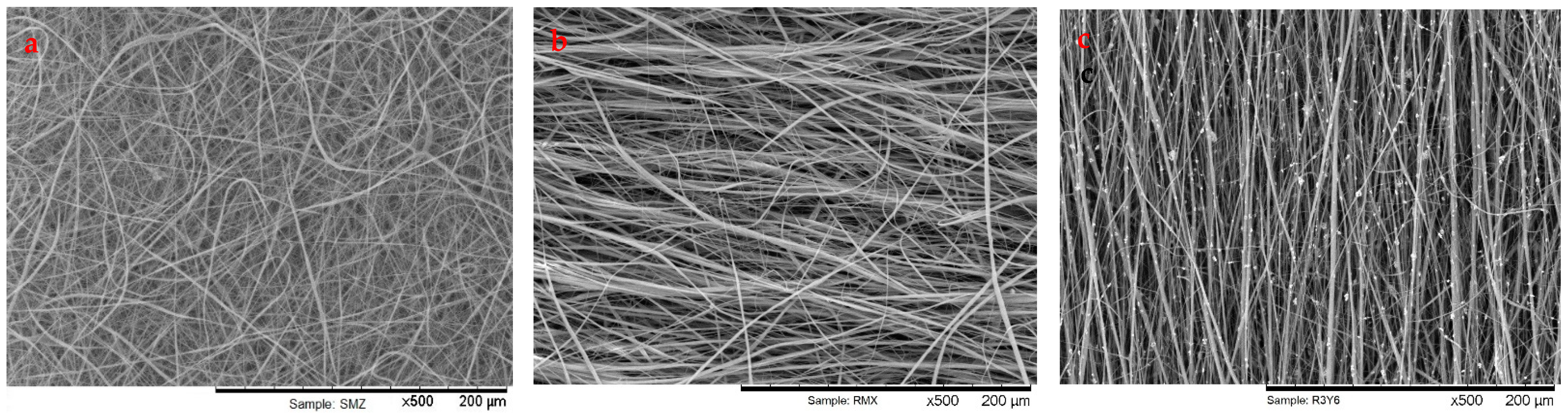
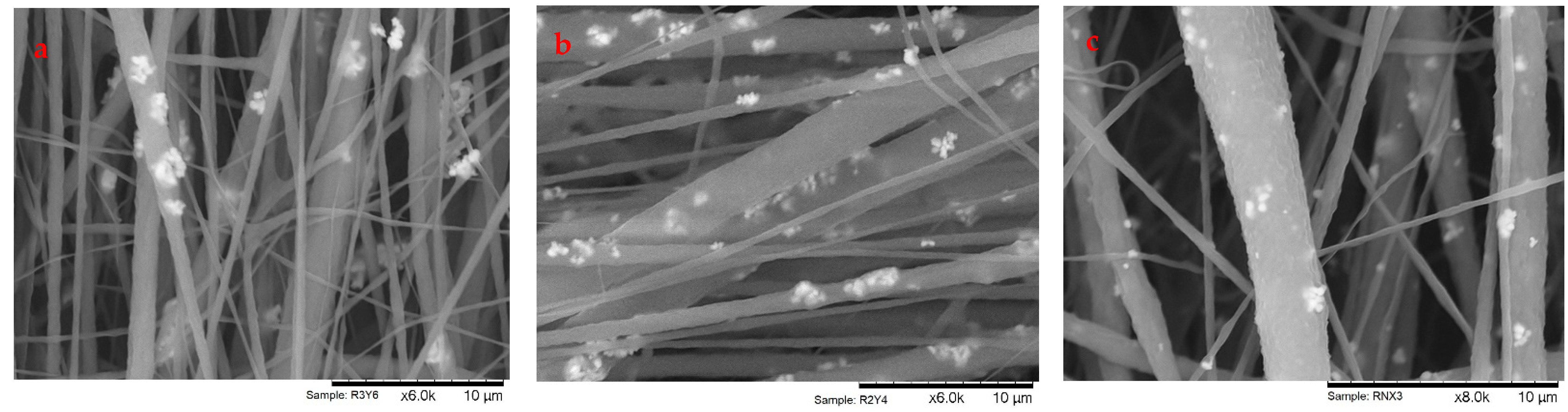
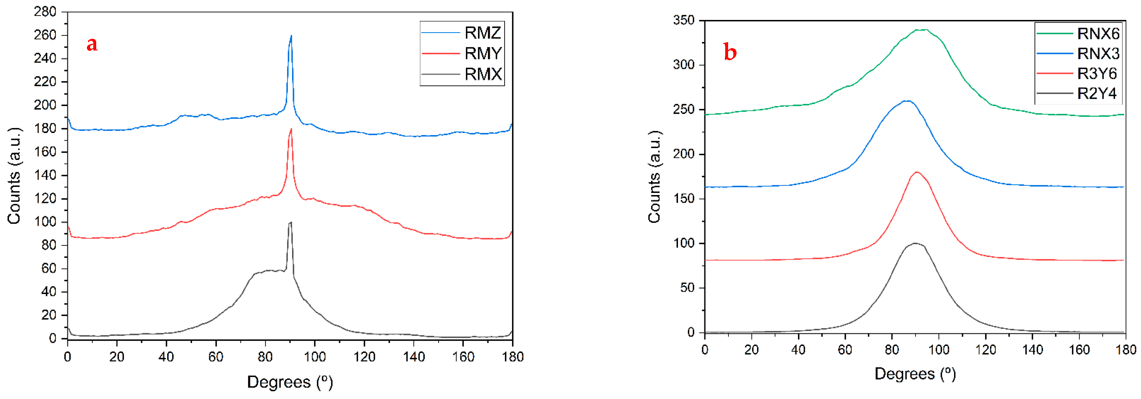
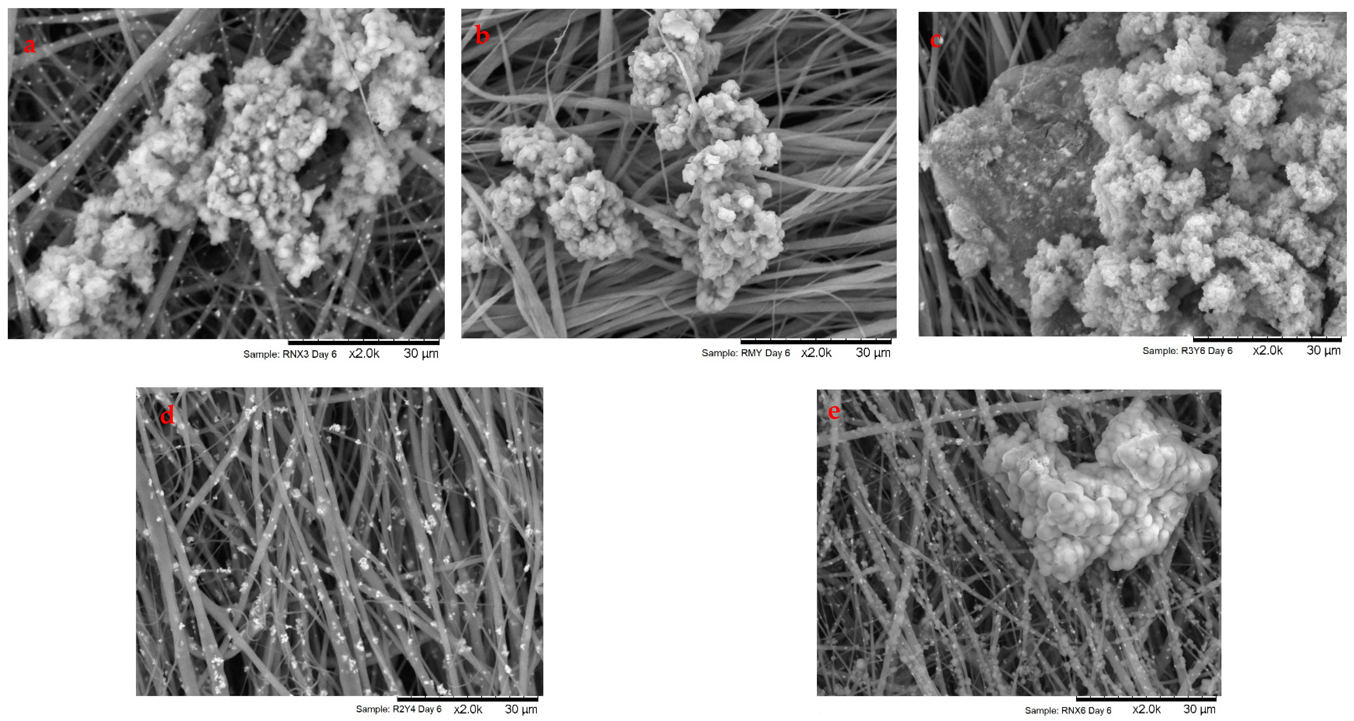
The electrospinning solution was developed first for static collector depositions, based on a previously reported work [18]. Many combinations between solvents ratio, PVDF weight percentage, applied voltage, and flow rate were tested. Thus, on the static collector, during deposition, fibers were analyzed to detect defects, such as droplets. When using the rotating collector, the air flow prevented this procedure. Ultimately, this quick analysis and the formation of glob-like structures at the tip of the needle were interpreted as signs to evaluate the quality of the fibers deposited. Before producing the particles embedded membranes, different concentrations of barium titanate were also tested regarding their ejectability from the syringe using a gauge 23.
The developed solution consisted of 1:2 ratio of DMF:Acetone (vol/vol) and 17% (weight percentage) of PVDF powder mixed for 1 h at 40 °C. At this stage, the BT particles were added to produce particle-embedded membranes and three different concentrations are reported, which were measured by the PVDF to barium titanate ratio (mass/mass).
This solution was used to produce all the membranes used on the static collector and rotating collector as well as to produce the particle-embedded membranes; all the settings used as described in Table 1 below, as well as the relevant membranes produced.
Although only eight different membranes were described during the analysis, determining the best parameters was done by trial and error where many combinations of parameters were tested and analyzed. From the three selected parameters determined for the pure PVDF membranes, the same procedure of trial and error was performed for the PVDF/BaTiO3 membranes where different concentrations of particles were tested.

3.2. SEM Analysis

A comparison between the best membranes of each composition and electrospinning parameters tested for the static collector, rotative collector, and embedded membranes can be observed in Figure 1, where membrane SMZ was produced on a static collector, membrane RMX was produced on the rotating drum equipment, and membrane R3Y6 was also produced on the rotating drum equipment but embedded with barium titanate particles.
As expected, the membranes produced with the static collector show no sign of alignment at all, whereas the rotating collector proved to promote the alignment of fibers significantly for RPM above 2500. Membrane R3Y6 showed the best alignment of all membranes. The membranes produced with the same set of electrospinning parameters, regardless of being with and without particles, exhibited the best alignment.
The distribution of particles can be observed on Figure 2, where each membrane used a different size of BT particles. There is not a significant difference in the distribution and embedding of the micrometer particles with the fibers. On the other hand, it is noticeable that the nanopowder is completely embedded inside the fiber strands of the membrane, even if some aggregates were formed.
The obtained SEM images allowed for the analysis of the diameter and alignment distributions of the produced membranes. This analysis was performed with the plugin OrientationJ from the software ImageJ using the obtained SEM images at 2000× magnification for the diameters (Table 2) and at 500× magnification for the alignment, which are evaluated graphically in Figure 3. Arbitrarily, the highest count of fibers was set as the 90° angle for an easier interpretation of the graph.
The results from measuring the diameters suggest that the presence of the barium titanate particles in the electrospinning deposition interferes with the formation of fibers, probably originating with the local electric field disturbance due to the presence of polarized piezoelectric BT particles, resulting in a single broad peak.
Observing the alignment distributions, membrane RMX looks to have the most coherence in orientation, as the left shoulder of the graph suggests that most of the fibers are aligned in the same direction (sharp peak in Figure 3a). For this reason, the parameters of membrane RMX were considered the best option achieved, along with the parameters from membrane RMY, which were then used for the particle-embedded membranes.
There is a clear difference in distribution between the membranes without particles from the membranes with particles. Membranes with no BT particles have some fibers more oriented, as the sharp peaks in Figure 3a show (at an angle of 90°). Looking at the wider peaks and comparing between the graphs of membranes with and without BT (Figure 3a,b), it seems that overall there is a narrow distribution of orientation angles for the fiber mats with BT (which can also be observed in Figure 1).
Considering the diameters, morphology, and alignment of the fibers, the best deposition parameters found were 18 kV, 1 mL/h, 3000 RPM, 15 cm of distance, and needle of gauge 23 for the rotative collector for both pure PVDF and particle-embedded membranes.
For membranes of PVDF (no BT particles), wider fibers were obtained. Regarding alignment angles, a broad peak was observed with a sharp peak superimposed on a wider peak, presenting overall a broader distribution of orientation of the fibers. For PVDF membranes with embedded BT particles, the fibers are narrower (see Table 2) and there is no sharp peak for the alignment. However, the FWHM for the wider peak is smaller than in the mat with just PVDF, meaning once again that the presence of barium titanate noticeably affects the deposition of the PVDF fibers.

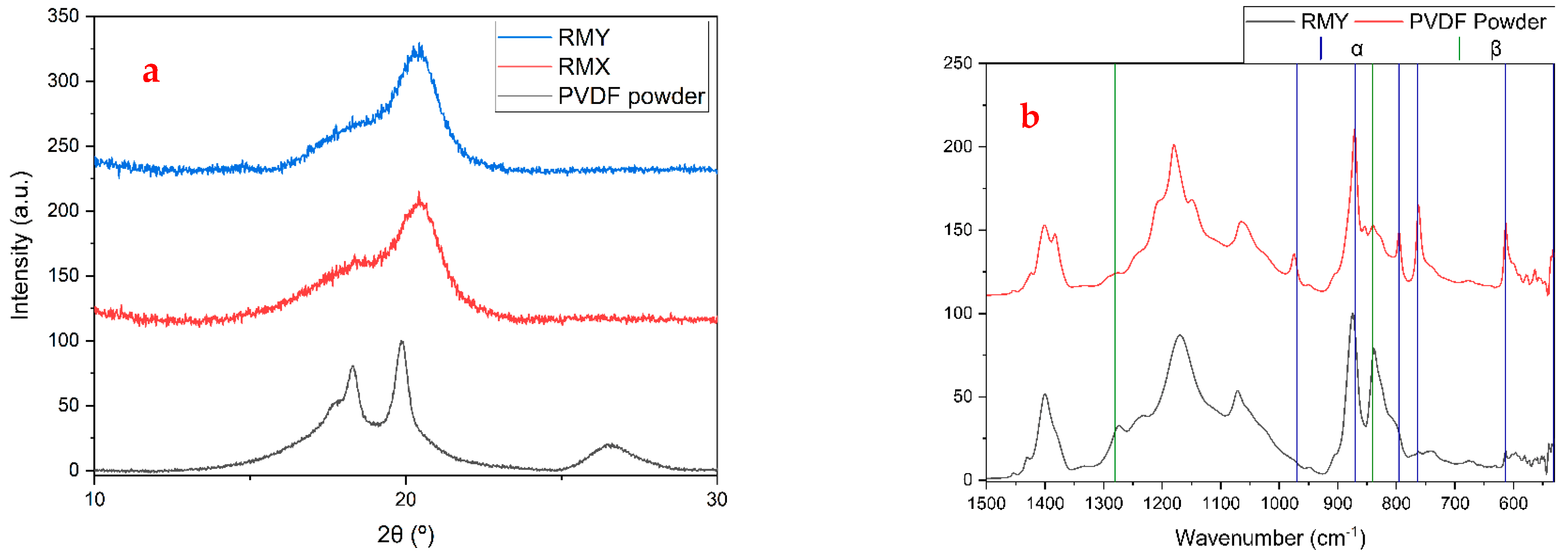
3.3. XRD and FTIR Analysis

According to the literature, the formation of β-phase in PVDF is promoted through electrospinning production, as the molecules are stretched by the influence of the electrical field necessary for the deposition, and the H and F atoms in its structure are arranged on different sides of the macromolecular backbone resulting in molecules presenting an electric dipole [18,19,20]. To observe this effect, XRD analysis was performed using the PVDF precursor powder and two membranes produced on the rotating collector (Figure 4a).
Comparing the obtained data with the literature [21,22], it is possible to see in Figure 4a that both RMY and RMX possess the characteristic XRD spectrum of β-phase PVDF assured by the disappearance of the peak near 26° and the increase of intensity of the peak found at 20°.
The FTIR analysis reassured the presence of β-phase in the produced membranes when compared to the PVDF powders Figure 4b. Observing the obtained data, it is possible to see three important distinctions between them, helping to prove the presence of β-phase PVDF in the membranes [21,22].
The α-phase peaks are located at 531, 614, 763, 796, 870, and 970 cm−1, while the β-phase peaks appear at 440, 470, 510, 840, and 1280 cm−1 [21,23,24]. The most important peak to differentiate the two phases is at 1280 and 840 cm−1, as none of them are present for the α-phase as can be seen in Figure 4b. The higher intensity of both peaks shows the prevalence of the β-phase.

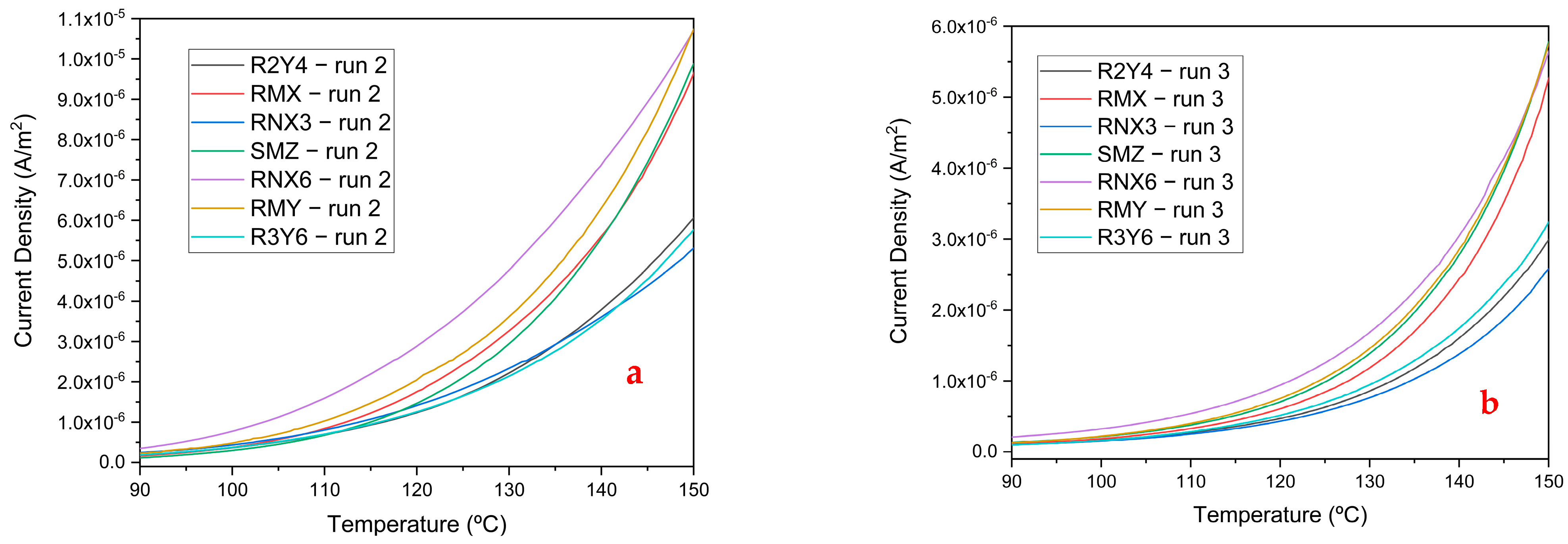
3.4. Thermally Stimulated Depolariation Currents Analysis

TSDC analysis was performed to evaluate the dielectric properties of chosen samples, which consisted of measuring the electrical current passing through each membrane while the temperature was increased at a constant rate. The electric charge detrapping and dipole disorientation will give rise to peaks in the thermogram. Characteristics, such as activation energy and relaxation time, can be determined from the TSDC graphs.
For our samples, the first run is not presented here because it served the purpose of letting the sample discharge any charges (mainly surface charges) that originated from the production of the membrane and were not related to its polarization and charges in deep traps. The results from dipole disorientation and charge detrapping would be masked by these charges with much faster decay rates.
Presented in Figure 5 is the thermogram for runs 2a and 3b, which were measured from 30 °C to 150 °C, heated at a rate of 2 °C/min, and without any further polarization of the samples (the thermograms presented start at 90 °C onwards, since no relevant features were found below this temperature). To avoid the melt of the membranes, no measurement was made above 150 °C (electrospun PVDF fibers melting temperature is 167.5 °C [22]).
All measurements had the form of an exponential curve, representing the initial rise of a peak that should have its maximum around 140 °C to 180 °C, where the dipolar relaxation of the crystalline phase occurs. The higher values for the current are related to PVDF and the lower ones to PVDF + BT. The exception is the RNX6 membrane, which has the highest content of BT particles of 280 μm diameter, which is supposed to be the cause for this higher response. Membrane R3Y6 also has the same concentration of particles, but these are almost 11 times bigger than the particles used for RNX6, at 3 µm to 280 nm, respectively. Between membrane RNX6 and R3Y6, there is a noticeable similarity in diameters, and R3Y6 actually presents a sharper peak in the alignment distribution (Table 2 and Figure 3b, respectively), which further establishes that the difference in current density of membrane RNX6 directly relates to the contribution of the BaTiO3 nanoparticles embedded in the fibers.
A decrease in current can be seen on the current values of run 3 when compared to run 2. This evidences the dipole orientation of the molecular chains during the electrospinning of the membranes. Gaur et al. [25] observed an increase in the current measured during TSDC with the increase of BT content in films of PVDF and nanoparticles of BT. This was not the case in the membranes produced in this work. As stated in the analysis of SEM images. one of the reasons for this might be that the presence of BT particles in electrospinning solution alters the fibers’ diameters and orientation, as seen previously, by generating higher local electric fields.

3.5. Cytotoxicity Analysis

The cytotoxicity analysis was performed to ensure the biocompatibility of barium titanate at different particle sizes and concentrations, as well as confirm the non-cytotoxicity of PVDF [26,27]. The testing consisted of preparing extracts for each sample that were then diluted three times by a factor of 2. Each consequent dilution was used to generate four replicas, meaning that, for each sample, 16 wells were prepared in groups of four.
To analyze the cytotoxicity, a redox indicator, Biotool Vita-blue Cell Viability Reagent, was used as an indicator of metabolic activity since the dehydrogenase enzymes present inside living cells can react with the resazurin agent, turning it into resofurin, and changing the medium from blue to pink. This color difference is then used as an indicator for the percentage of living cells when compared with control mediums to which the percentages presented are standardized as 100% [28].
The results showed that neither the PVDF nor the barium titanate powders indicated any signs of cytotoxicity, as the values obtained for the percentage of living cells all fell around the 100% mark, as shown in Table 3.

3.6. Bioactivity Analysis

The bioactivity analysis was performed by submerging samples membranes RMY, R2Y4, R3Y6, RNX6, and RNX3 in an SBF solution kept at 37 °C to mimic average body temperature, for 1 day, 3 days, and 6 days. This was done without applying mechanical stimuli to the membranes, meaning that the bioactivity observed would be independent from the piezoelectric proprieties of the membranes but related to its surface charge. All samples were analyzed through SEM images and EDS data. Except for RMY, other membranes presented bioactivity between the third and sixth day, whereas membrane RMY displayed bioactivity starting on the first day.
Through Figure 6, can be observed the dispersion of the CaP structures on samples after 6 days of immersion. Noticeably, membrane R2Y4 lacked the presence of any CaP crystals, whereas RMY was the one that showed the earliest signs of bioactivity. The interpretation of these results leads to the belief that the presence of BT particles hinders the bioactivity of PVDF fibers.
Following the results from the EDS analysis, not shown here, the high quantities of carbon and calcium throughout the formed structures lead to the suspicion that the formation of CaCO3 could be the reason for this, since no fibers, which do contain carbon, run through the zone selected for EDS [29].
The percentual quantity of Ca and P as the expected ratio of Ca/P should be near 1.67 (the ratio for hydroxyapatite) and almost all samples present a value near it, except for RNX6. However, there is a high chance that this is not all due to the formation of calcium phosphate and includes the presence of other compounds such as carbonates. This is further supported as membrane RNX6 shows a ratio 2.4 times greater than predicted, pointing to the possibility of other compounds containing calcium, such as the mentioned calcium carbonate or tetra calcium phosphate (Ca4P2O9); these results originated from the EDS analysis and are summarized in Table 4.

4. Conclusions

The formation of β-phase PVDF was verified for all the produced membranes using the XRD and FTIR, confirming that the electrospinning process directly promotes the formation of β-phase. The membranes embedded with BT particles showed similar characteristics to the PVDF-only membranes in terms of morphology and alignment; however, there seems to exist an interaction between the PVDF monomers and the barium titanate particles that decreases the diameter of the fibers using the same parameters. This reassures that, while the parameters mentioned previously work to produce fibers, there may be room for tweaking the process towards more consistent results.
The TSDC results showed lower currents registered for most of the embedded membranes when compared to the pure PVDF membranes. The probable cause for this could be the presence of the barium titanate particles during the electrospinning process as the local electric field gets disturbed, which consequently could hinder the alignment of the PVDF monomers in the fibers. This is further supported because the average diameter of the fibers was lower than pure PVDF membranes; however, further analysis of the embedded membranes would be needed. The only exception, with highest currents values of all the membranes, occurred for the one with highest content of BT particles of diameter 280 nm. This type of membrane also gave inconsistent results in the bioactivities assays, where the presence of CaCO3 was detected.
The cytotoxicity analysis revealed that neither the PVDF nor the particles used presented cytotoxic properties. On the other hand, the bioactivity showed to be diminished for the BT-embedded membranes when compared to a pure PVDF membrane, with the most probable cause being the same as described for the TSDC results.

Author Contributions

Conceptualization, M.C.L., J.P.M.R.B. and S.D.A.; methodology, M.C.L., J.P.M.R.B. and S.D.A.; validation, M.C.L. and J.P.M.R.B.; formal analysis, S.D.A., J.P.M.R.B., J.C.S. and M.C.L.; writing—original draft preparation, S.D.A.; writing—review and editing, M.C.L., J.P.M.R.B. and S.D.A.; supervision, M.C.L. and J.P.M.R.B.; funding acquisition, J.C.S., J.P.M.R.B. and M.C.L. All authors have read and agreed to the published version of the manuscript.

Funding

This work was financed by national funds from FCT—Fundação para a Ciência e a Tecnologia, I.P., in the scope of the projects LA/P/0037/2020, UIDP/50025/2020, and UIDB/50025/2020 of the Associate Laboratory Institute of Nanostructures, Nanomodelling and Nanofabrication—i3N.

Data Availability Statement

The data presented in this study are available on request from the corresponding author.

Conflicts of Interest

The authors declare no conflict of interest.

References

  1. Macedo, F.; Ladeira, K.; Pinho, F.; Saraiva, N.; Bonito, N.; Pinto, L.; Gonçalves, F. Bone metastases: An overview. Oncol. Rev. 2017, 11, 321. [Google Scholar] [CrossRef] [Green Version]
  2. Schlickewei, C.W.; Kleinertz, H.; Thiesen, D.M.; Mader, K.; Priemel, M.; Frosch, K.-H.; Keller, J. Current and Future Concepts for the Treatment of Impaired Fracture Healing. Int. J. Mol. Sci. 2019, 20, 5805. [Google Scholar] [CrossRef] [PubMed] [Green Version]
  3. Fukada, E.; Yasuda, I. On the Piezoelectric Effect of Bone. J. Phys. Soc. Jpn. 1957, 12, 1158–1162. [Google Scholar] [CrossRef]
  4. Baxter, F.R.; Bowen, C.; Turner, I.G.; Dent, A.C.E. Electrically Active Bioceramics: A Review of Interfacial Responses. Ann. Biomed. Eng. 2010, 38, 2079–2092. [Google Scholar] [CrossRef] [PubMed]
  5. Jacob, J.; More, N.; Kalia, K.; Kapusetti, G. Piezoelectric smart biomaterials for bone and cartilage tissue engineering. Inflamm. Regen. 2018, 38, 2. [Google Scholar] [CrossRef] [Green Version]
  6. Khare, D.; Basu, B.; Dubey, A.K. Electrical stimulation and piezoelectric biomaterials for bone tissue engineering applications. Biomaterials 2020, 258, 120280. [Google Scholar] [CrossRef]
  7. Xu, J.; Wang, W.; Clark, C.C.; Brighton, C.T. Signal transduction in electrically stimulated articular chondrocytes involves translocation of extracellular calcium through voltage-gated channels. Osteoarthr. Cartil. 2009, 17, 397–405. [Google Scholar] [CrossRef] [PubMed] [Green Version]
  8. More, N.; Kapusetti, G. Piezoelectric material—A promising approach for bone and cartilage regeneration. Med. Hypotheses 2017, 108, 10–16. [Google Scholar] [CrossRef]
  9. Mishra, S.; Unnikrishnan, L.; Nayak, S.K.; Mohanty, S. Advances in Piezoelectric Polymer Composites for Energy Harvesting Applications: A Systematic Review. Macromol. Mater. Eng. 2019, 304, 180046. [Google Scholar] [CrossRef] [Green Version]
  10. Li, H.; Tian, C.; Deng, Z.D. Energy harvesting from low frequency applications using piezoelectric materials. Appl. Phys. Rev. 2014, 1, 041301. [Google Scholar] [CrossRef]
  11. Houis, S.; Engelhardt, E.; Wurm, F.; Gries, T. Application of polyvinylidene fluoride (PVDF) as a biomaterial in medical textiles. In Medical and Healthcare Textiles; Woodhead Publishing: Sawston, UK, 2010; pp. 342–352. [Google Scholar] [CrossRef]
  12. Shuai, C.; Liu, G.; Yang, Y.; Yang, W.; He, C.; Wang, G.; Liu, Z.; Qi, F.; Peng, S. Functionalized BaTiO3 enhances piezoelectric effect towards cell response of bone scaffold. Colloids Surfaces B Biointerfaces 2020, 185, 110587. [Google Scholar] [CrossRef] [PubMed]
  13. Haider, A.; Haider, S.; Kang, I.-K. A comprehensive review summarizing the effect of electrospinning parameters and potential applications of nanofibers in biomedical and biotechnology. Arab. J. Chem. 2018, 11, 1165–1188. [Google Scholar] [CrossRef]
  14. Kapat, K.; Shubhra, Q.T.H.; Zhou, M.; Leeuwenburgh, S. Piezoelectric Nano-Biomaterials for Biomedicine and Tissue Regeneration. Adv. Funct. Mater. 2020, 30, 1909045. Available online: https://onlinelibrary.wiley.com/doi/abs/10.1002/adfm.201909045 (accessed on 21 October 2022). [CrossRef] [Green Version]
  15. Li, Y.; Liao, C.; Tjong, S.C. Electrospun Polyvinylidene Fluoride-Based Fibrous Scaffolds with Piezoelectric Characteristics for Bone and Neural Tissue Engineering. Nanomaterials 2019, 9, 952. [Google Scholar] [CrossRef] [PubMed] [Green Version]
  16. Oyane, A.; Kim, H.; Furuya, T.; Kokubo, T.; Miyazaki, T.; Nakamura, T. Preparation and assessment of revised simulated body fluids. J. Biomed. Mater. Res. 2003, 65, 188–195. [Google Scholar] [CrossRef]
  17. Tas, A.C. Synthesis of biomimetic Ca-hydroxyapatite powders at 37°C in synthetic body fluids. Biomaterials 2000, 21, 1429–1438. [Google Scholar] [CrossRef]
  18. Infante, T.P. Tiago Pinheiro Infante Optimizing the Osteogenic Potential of Electrospun PVDF Matrixes. Available online: http://hdl.handle.net/10362/92314 (accessed on 1 September 2022).
  19. Lim, Y.; Kim, S.; Seo, Y. Enhancement of β-phase in PVDF by electrospinning. AIP Conf. Proc. 2015, 1664, 070006. [Google Scholar] [CrossRef]
  20. He, Z.; Rault, F.; Lewandowski, M.; Mohsenzadeh, E.; Salaün, F. Electrospun PVDF Nanofibers for Piezoelectric Applications: A Review of the Influence of Electrospinning Parameters on the β Phase and Crystallinity Enhancement. Polymers 2021, 13, 174. [Google Scholar] [CrossRef]
  21. Esterly, D.M.; Love, B.J. Phase transformation to ?-poly(vinylidene fluoride) by milling. J. Polym. Sci. Part B Polym. Phys. 2004, 42, 91–97. [Google Scholar] [CrossRef]
  22. Mokhtari, F.; Latifi, M.; Shamshirsaz, M. Electrospinning/electrospray of polyvinylidene fluoride (PVDF): Piezoelectric nanofibers. J. Text. Inst. 2016, 107, 1037–1055. [Google Scholar] [CrossRef]
  23. Bormashenko, Y.; Pogreb, R.; Stanevsky, O. Vibrational spectrum of PVDF and its interpretation. Polym. Test. 2004, 23, 791–796. [Google Scholar] [CrossRef]
  24. Benz, M.; Euler, W.B. Determination of the crystalline phases of poly(vinylidene fluoride) under different preparation conditions using differential scanning calorimetry and infrared spectroscopy. J. Appl. Polym. Sci. 2003, 89, 1093–1100. [Google Scholar] [CrossRef]
  25. Gaur, M.S.; Singh, P.K.; Ali, A.; Singh, R. Thermally stimulated discharge current (TSDC) characteristics in β-phase PVDF–BaTiO3 nanocomposites. J. Therm. Anal. 2014, 117, 1407–1417. [Google Scholar] [CrossRef]
  26. Ball, J.P.; Mound, B.A.; Nino, J.C.; Allen, J.B. Biocompatible evaluation of barium titanate foamed ceramic structures for orthopedic applications. J. Biomed. Mater. Res. Part A 2014, 102, 2089–2095. [Google Scholar] [CrossRef] [PubMed]
  27. Gryshkov, O.; AL Halabi, F.; Kuhn, A.I.; Leal-Marin, S.; Freund, L.J.; Förthmann, M.; Meier, N.; Barker, S.-A.; Haastert-Talini, K.; Glasmacher, B. PVDF and P(VDF-TrFE) Electrospun Scaffolds for Nerve Graft Engineering: A Comparative Study on Piezoelectric and Structural Properties, and In Vitro Biocompatibility. Int. J. Mol. Sci. 2021, 22, 11373. [Google Scholar] [CrossRef] [PubMed]
  28. Blaen, P.J.; Brekenfeld, N.; Comer-Warner, S.; Krause, S. Multitracer Field Fluorometry: Accounting for Temperature and Turbidity Variability during Stream Tracer Tests. Water Resour. Res. 2017, 53, 9118–9126. [Google Scholar] [CrossRef]
  29. Mozafari, M.; Banijamali, S.; Baino, F.; Kargozar, S.; Hill, R.G. Calcium carbonate: Adored and ignored in bioactivity assessment. Acta Biomater. 2019, 91, 35–47. [Google Scholar] [CrossRef]
Figure 1. SEM images of membranes (a) SMZ, (b) RMX, and (c) R3Y6 at 500× magnification.
Macromol 02 00034 g001
Figure 2. SEM images of membranes: (a) R3Y6 (6000×), (b) R2Y4 (6000×), and (c) RNX3 (8000×).
Macromol 02 00034 g002
Figure 3. Alignment distribution graphs: (a) membranes without particles and (b) membranes with particles.
Macromol 02 00034 g003
Figure 4. (a) XRD graphs of membranes RMY, RMX, and the PVDF powder, and (b) FTIR spectra of membrane RMY and PVDF powder overlayed with peak values from the α and β phases.
Macromol 02 00034 g004
Figure 5. TSDC data from run 2 (a) and run 3 (b) of membranes R2Y4, RMX, RNX3, SMZ, RNX6, and RMY.
Macromol 02 00034 g005
Figure 6. SEM images at 500× magnification of the membranes (a) RNX3, (b) RMY, (c) R3Y6, (d) R2Y4, and (e) RNX6 after 6 days of immersion in SBF.
Macromol 02 00034 g006
Table 1. Electrospinning parameters used for all membranes characterized; all membranes were produced with 18 kV, 15 cm from tip-to-collector and needle gauge 23.
MembraneRPMFlow Rate (mL/h)Volume
(mL)
PVDF:BT
Ratio
SMZ-0.750.5-
RMX250011-
RMY300011-
RMZ30000.751-
R3Y63000116:1 (3 µm)
R2Y43000114:1 (2 µm)
RNX32500113:1 (280 nm)
RNX62500116:1 (280 nm)
Table 2. Fiber diameters for the different membranes, obtained through ImageJ from SEM data.
MembraneDiameter (µm)
RMX1.20 ± 0.15
RMY1.15 ± 0.12
RMZ0.72 ± 0.13
R3Y60.70 ± 0.10
R2Y40.89 ± 0.13
RNX30.90 ± 0.13
RNX60.73 ± 0.10
Table 3. Results from the cytotoxicity analysis.
MembraneLiving Cells (%)Uncertainty (%)
RMY98±3
RNX3107±5
RNX6112±5
R3Y6109±7
R2Y4103±7
Table 4. Ratio of Ca/P present in the membranes submerged for 6 days in SBF.
MembraneCaPCa/P
R3Y69.225.051.83
RNX39.365.571.69
RNX638.359.544.02
RMY9.484.951.92
Publisher’s Note: MDPI stays neutral with regard to jurisdictional claims in published maps and institutional affiliations.

