1. Introduction
The basic working principle of hydraulic seals is to prevent contaminants from entering the system or hydraulic oil from leaking by providing a proper seal for the hydraulic system. Hydraulic seals are an important part of numerous disciplines such as the aerospace, automotive, medical, and natural gas industries. Although hydraulic seals are an inexpensive consumable item, they have a vital role in the proper function of hydraulic systems. In the aviation field, with the development of lightweight aircraft, the performance requirements for hydraulic sealing structures such as aircraft actuators have become more stringent. For instance, the relative speeds at hydraulic seals are growing, working temperatures are rising, and maximum working pressures are increasing [
1]. Under harsh temperature and pressure conditions, sealing components are easily worn, thereby leading to sealing failures and possibly resulting in accidents [
2,
3,
4]. Therefore, it is essential to study the failure mechanism of hydraulic seals in harsh environments and to propose a set of schemes to optimize their sealing performance.
Conventional tribological theory holds that smoother surface leads to superior tribological performance. Therefore, in the past, researchers improved tribological performance by enhancing the surface precision of materials. However, subsequent research revealed that uneven surfaces with micro- or nanotextures sometimes possessed superior tribological properties [
5,
6,
7]. Cheng [
8] studied the effect of surface texture on the tribological properties of PEO/PTFE coatings in heavy-duty long-life aluminum alloys. The textured PEO/PTFE coating was found to have excellent self-lubricating properties with a lower friction coefficient compared to untextured surfaces due to the formation of a continuously lubricating PTFE film on the worn surface. Hiba Jendoubi [
9] used a femtosecond laser to texture the surface of PTFE and investigated its tribological properties after the textured treatment. Results indicated that the surface friction coefficient of the textured treatment increased. This may be because high pressure in the contact causes the fluid to partially or completely fill the cavity, eddy currents appear in the cavity, and friction increases due to viscous dissipation. It is apparent that various texture treatments have different effects on tribological properties, and it is necessary to systematically study the effects of texture treatments to more effectively utilize this technology and improve the performance of sealing systems.
In terms of improving the tribological properties of materials, research over the past half-century has primarily focused on material modification. Later, it was established that surface texture treatment played a significant role in improving sealing performance in the lubricated state. As a result, this approach gradually became a common way of effectively improving tribological properties. The principle of hydrodynamic pressure reveals the working principles of surface texture technology in the state of fluid lubrication. Due to the relative motion of the friction pair, the fluid produces a hydrodynamic pressure effect at the converging wedge, which increases fluid pressure. Cavitation pressure does not drop to the theoretical value, so additional hydrodynamic pressure is generated in the fluid film on the textured surface, thereby increasing the bearing capacity [
10]. Experimental research has revealed that under vacuum and non-lubricated conditions, surfaces with grooves have a lower friction coefficient than smooth surfaces [
11]. When the lubrication conditions are boundary lubrication and the working conditions are low speed and heavy load, it is difficult to form a lubricating oil film between the friction pairs due to the low relative speed. At this time, the lubricating oil is stored in the surface texture and is squeezed out under the load to improve lubrication conditions in the surrounding area [
12]. The presence of grooves on textured surfaces effectively reduces the actual contact area of the friction surface, thus reducing friction [
13]. While there are several theoretical studies on the effect of texture treatment on material properties in the lubricated state, there are very few experimental studies on the effect of different texture parameters on sealing performance in the lubricated state at high rotational speeds. Corresponding experimental simulations are relatively difficult, and the main purpose is to qualitatively study and characterize the influence of different texture parameters on sealing performance under lubricated conditions. Therefore, scholars generally use simulations to analyze different textures, applying the influence of certain parameters on sealing performance in the lubricated state.
In the simulation research on the effects of surface texture on the surface tribological properties of materials, the Reynolds and Navier–Stokes (N-S) equations are generally used to simulate the lubrication characteristics of textured friction surfaces under fluid lubrication. The Reynolds equation mainly solves the effect of texture parameters on fluid lubrication through programming, while the N-S equation is simulated using computational fluid dynamics (CFD) software such as FLUENT. Fu [
14] employed numerical simulations to study the pressure distribution of lubricants when the smooth slider and the textured slider moved relative to each other and studied the effect of the parabolic grooved surface texture on hydrodynamic lubrication performance. In addition, Fu proposed an evaluation criterion of the hydrodynamic effect of dimensionless mean pressure as a function of minimum oil film thickness, groove width, groove depth, spacing, and direction angle. Xing [
15] employed the Reynolds equation to establish a theoretical model of the friction pair surface and studied the hydrodynamic lubrication of the sliding contact surface with rectangular microtexture using a numerical calculation method. Moreover, the oil film pressure was applied to evaluate the hydrodynamic lubrication effect. Numerical analysis results indicated that a staggered arrangement of rectangular micro-dimples strengthened hydrodynamic lubrication and the effect was best when the staggered angle was 72°. Using the N-S equation as a basis, Shen [
16] applied the computational fluid dynamics module of COMSOL Multiphysics to calculate the pressure and velocity distribution of the lubricant under different geometric parameters such as distribution and arrangement of the friction pair surface with a herringbone texture. In this way, the influence of the herringbone texture on lubricating performance was analyzed. Luís Vilhena [
17] used computational fluid dynamics numerical analysis to study the effect of surface texture treatment with different texture shapes on the tribological properties of the friction pair. This paper emphasizes that it is unrealistic to use CFD to directly analyze a practical problem that may have thousands of micro-pits. Therefore, this problem can be modified into the study of the hydrodynamic performance of a single unit of periodic micro-dimple patterns to qualitatively reflect overall hydrodynamic performance. With the development of lightweight components, hydraulic sealing systems must function in devices such as aircraft actuators under more extreme temperatures, pressures, speeds, and other working conditions. Thus, problems such as high sealing material wear rate and large hydraulic oil leakage often occur. Hence, in this paper, we refer to the concepts of previous simulations and use FLUENT software simulations to study the influence of PTFE material surface texture treatment on the friction pair sealing performance in the lubricated state from the perspectives of oil film bearing capacity and leakage rate. The texture parameters are texture shape, depth, width, and texture area ratio.
3. Results and Discussion
3.1. Data Processing Method
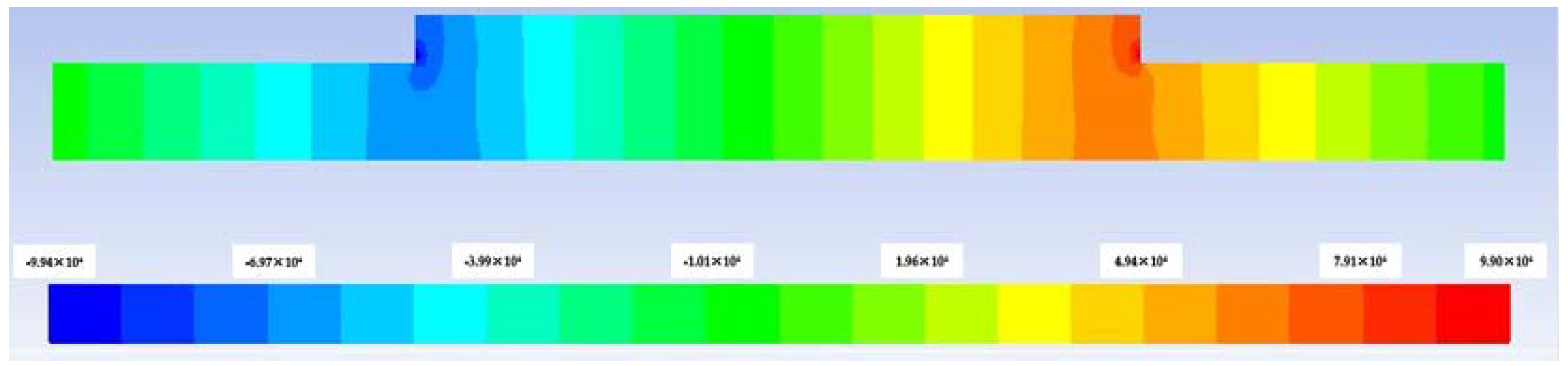
By integrating the pressure data, the data of the simulation results for the pressure distribution of the flow field are derived and the bearing capacity is obtained.
Figure 5 shows the pressure distribution cloud map when the texture depth is 5 μm. A high-pressure region appears in the textured convergent wedge, with a maximum value of approximately 9.90 × 10
4 Pa. A negative pressure region forms at the divergent wedge of the texture, and the minimum value is around −9.90 × 10
4 Pa. Cavities are generated at the divergent wedge, so to prevent the development of negative pressure, the Half-Sommerfeld cavitation boundary condition is used for processing mathematical calculations. To determine the boundary conditions, after the iterative calculation is completed and the oil film pressure distribution is obtained, all the negative pressures in the pressure data are reset to zero and the processed data are integrated to obtain the oil film bearing capacity. Due to the varying texture widths and total lengths of texture elements under the same area ratio, the bearing areas corresponding to the bearing capacity obtained from the integral are different. Thus, it is impossible to compare and judge sealing performance. Consequently, the bearing surface areas are unified and the bearing capacities are compared by calculating the bearing capacity with an area of 1 mm
2. The oil film bearing capacity is obtained through subsequent calculations to compare the influence of texture parameters on oil film bearing capacity.
For sealing materials, texture treatment has a certain impact on sealing performance Therefore, it is necessary to consider the effect of surface texture treatment on leakage. The leakage amount is the flow rate at the inlet and the outlet. In addition, the size of the leakage is visually observed and the leakage amount is converted into a leakage rate per 1 mm2 at a certain point in time.
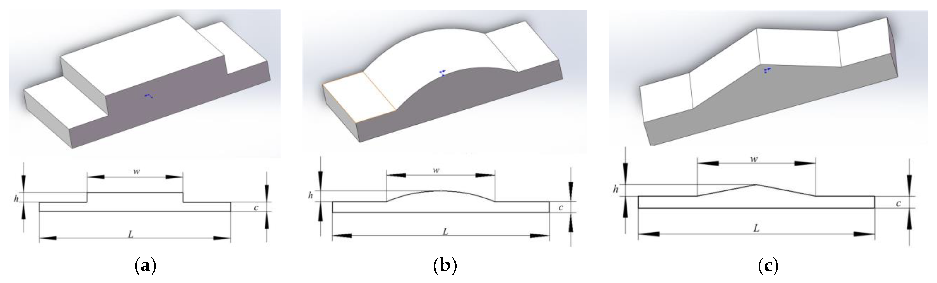
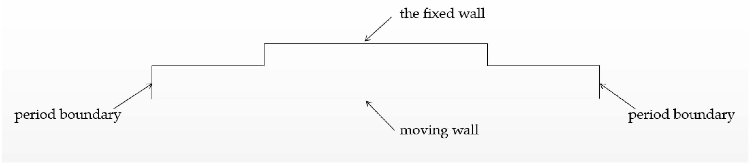
Due to the setting of the symmetry plane, the width of the texture element does not affect the calculation results. Thus, to reduce the number of calculations, the element width should be as small as possible. Among the surface texture parameters of the texture treatment, parameters such as texture shape, depth, size, and area ratio may have a significant impact on oil film bearing capacity and leakage. Therefore, in this paper, we mainly study the influence of depth, width, and area ratio of the groove texture on oil film bearing capacity and leakage. The three groove texture cross-sectional shapes selected for this study are rectangular, triangular, and arc-shaped.
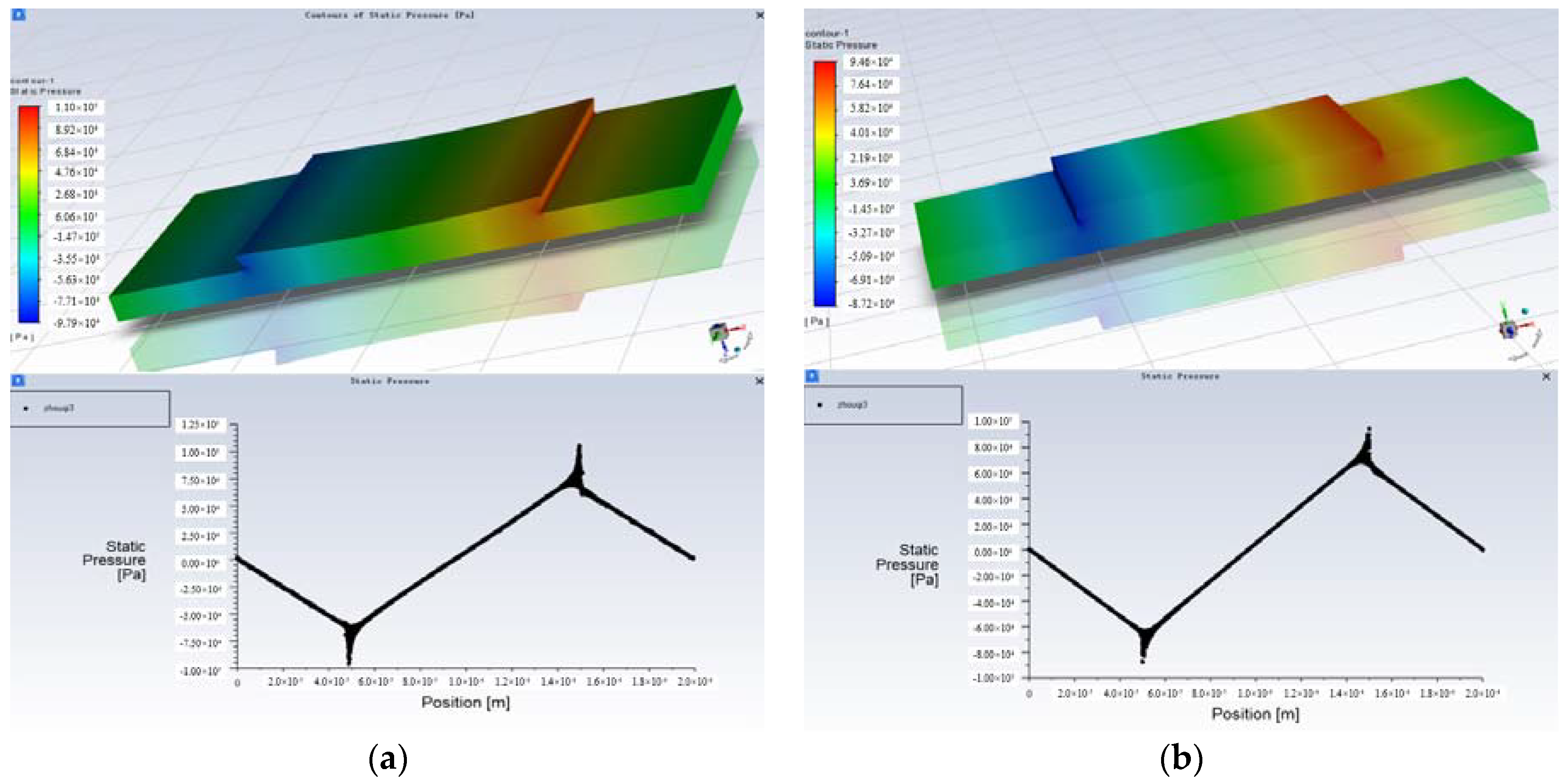
Figure 6 shows the stress distribution cloud diagram and pressure distribution curve on the section using either PTFE or a rigid body as the sealing material and with constant texture parameters. The calculated oil film bearing capacities are 16.856 N and 17.365 N, respectively, displaying a difference of less than 5%. Additionally, the calculated leakage rates are 4.75057 g/s and 4.74997 g/s, with a difference much lower than 1%.
When the sealing material is PTFE, the strain of the sealing material must be considered. The solution process is relatively complicated and the calculation results are close to those of a rigid body sealing material. Therefore, setting the sealing material as a rigid body has little effect on the qualitative evaluation of the influence of varying texture parameters on sealing performance. Thus, in the simulation calculations of this paper, the sealing material is set as a rigid body to calculate the oil film bearing capacity and leakage.
3.2. Effect of Texture Depth on Bearing Capacity and Leakage
The oil film thickness is set to 10 μm, the texture width is 100 μm, and the area ratio is 50%.
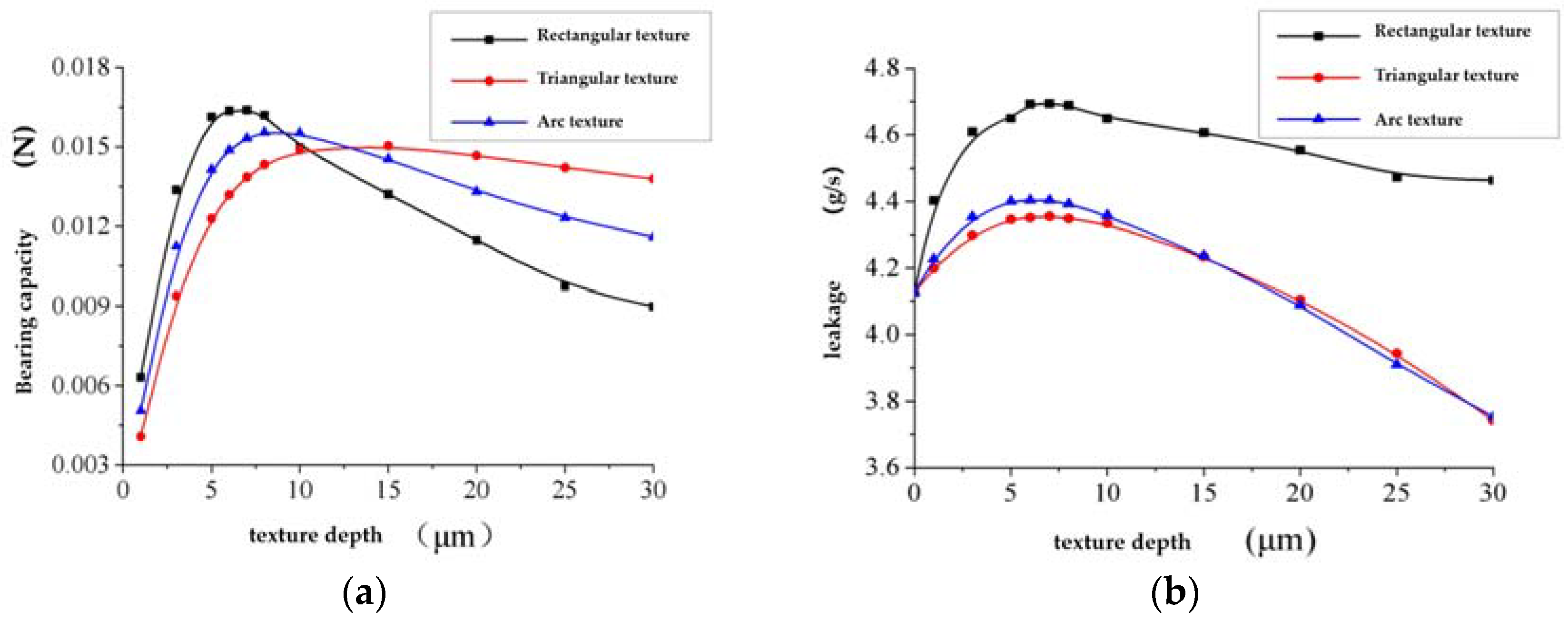
Figure 7 presents the results of the simulation analysis on the effect of different texture depths on bearing capacity and leakage.
The figure shows that with an increase in texture depth, the bearing capacity first increases and then decreases. However, the extremes generated by different texture types vary significantly. When other conditions are constant, there is an optimal texture depth value that results in a peak dynamic pressure effect. In addition, different texture types have dissimilar optimal values. Leakage also initially increases and then decreases with a rise in texture depth. However, leakage with the triangular texture and the arc-shaped texture falls rapidly as texture depth increases, and the leakage is much smaller than that of the rectangular texture at the same texture depth. Moreover, when the texture depth exceeds 20 μm, the leakage amount is much smaller than when there is no texture.
Furthermore, higher bearing capacities result in less leakage and better sealing performance. Therefore, considering the above results, the triangular texture with a texture depth of more than 20 μm should be selected for the grooved texture.
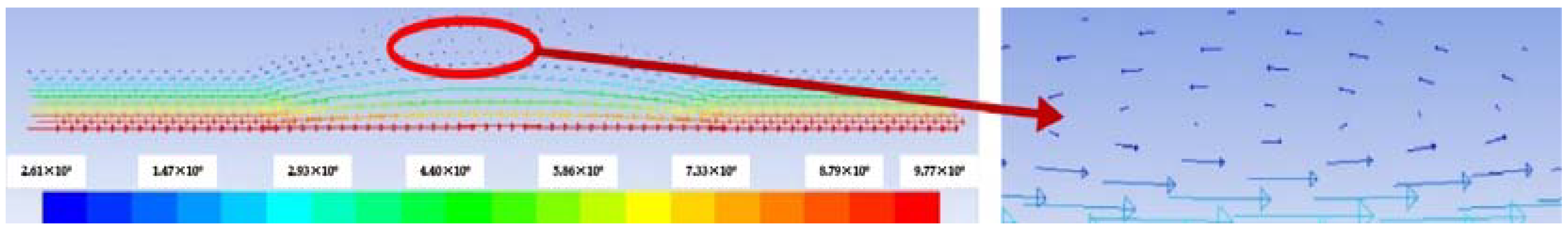
Figure 8 displays the flow field velocity vector diagram of the arc-shaped texture when the texture depth is 10 μm. It reveals that there is a reverse flow in the flow field at the bottom of the texture, which suggests that the reverse flow leads to changes in the bearing capacity. In addition, variations in texture depth influence leakage rates.
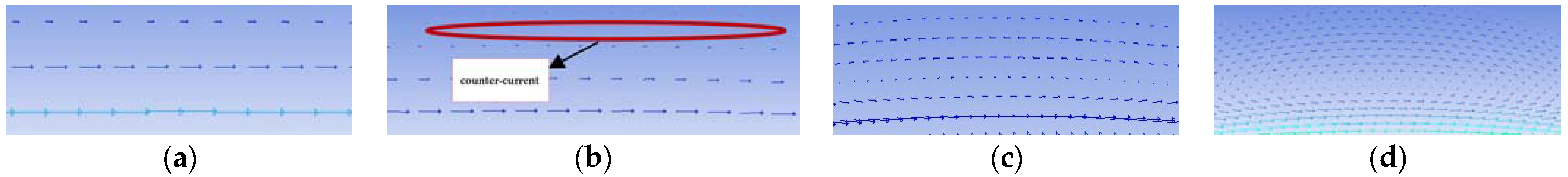
Figure 9 shows the velocity vector diagram under different arc-shaped texture depths. When h = 1 μm, there is no backflow at the bottom of the texture. In addition, when h = 5 μm, there is a weak backflow, and the backflow increases with rising texture depths. When h > 10 μm, the backflow area covers almost the entire texture bottom.
In theory, larger texture depths result in stronger dynamic pressure effects, but the existence of countercurrent weakens the influence of the dynamic pressure effect. When the texture depth is small and there is a weak countercurrent, increased texture depths lead to a stronger dynamic pressure effect and larger bearing capacity. However, when the texture depth is large, the countercurrent region fully forms. The reverse flow impairs fluid pressure, exceeding the dynamic pressure effect at a certain depth. Consequently, the bearing capacity decreases, so the bearing capacity first rises and then falls.
Leakage is also related to the dynamic pressure effect and the reverse flow phenomenon. The leakage rate varies with changes in fluid pressure. In addition, the occurrence of reverse flow reduces the outflow of a portion of the fluid and even exceeds the effect of pressure when the reverse flow is strong. As a result, the leakage rate may be lower than the untextured case when the texture depth is large.
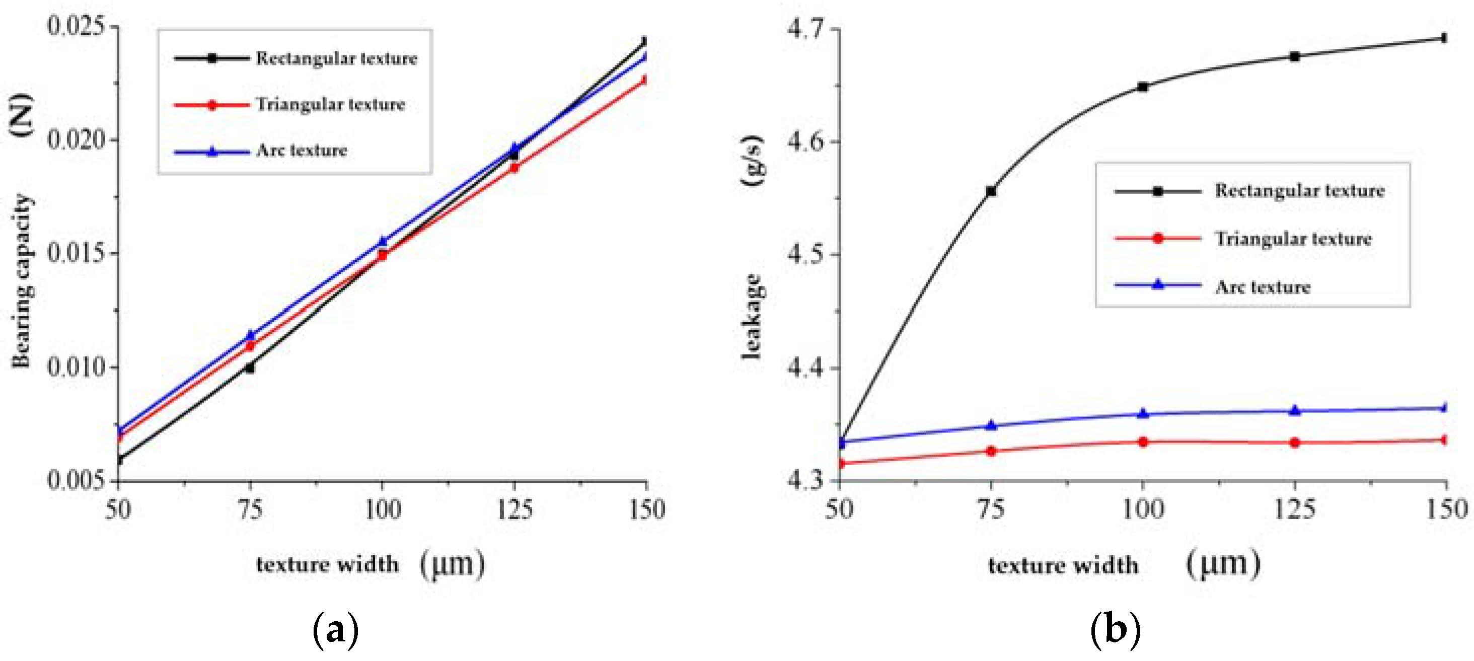
3.3. Effect of Texture Width on Bearing Capacity and Leakage
Here, the oil film thickness is set to 10 μm, the texture depth is 10 μm, and the area ratio is 50%. Results from the simulation analysis of bearing capacity and leakage with different texture widths are shown in
Figure 10.
It can be seen from the figure that larger texture widths result in greater oil film bearing capacities. In addition, the texture width has a linear relationship with the oil film bearing capacity. This is because an increase in texture width expands the size of the flow field convergence area, thereby increasing the oil film bearing capacity. Moreover, larger texture widths lead to greater leakage. The triangular and arc-shaped textures witness a marginal increase, while the leakage of the rectangular texture increases significantly with rising texture widths. In addition, at a constant texture width, the leakage rate of the rectangular texture is much larger than those of the triangular and the arc-shaped textures.
As the bearing capacity rises, the leakage rate falls, resulting in superior sealing performance. Therefore, it is appropriate to select triangular or arc-shaped textures with larger widths for the groove-type texture. Between them, the triangular texture has a weaker bearing capacity but less leakage than the circular arc texture.
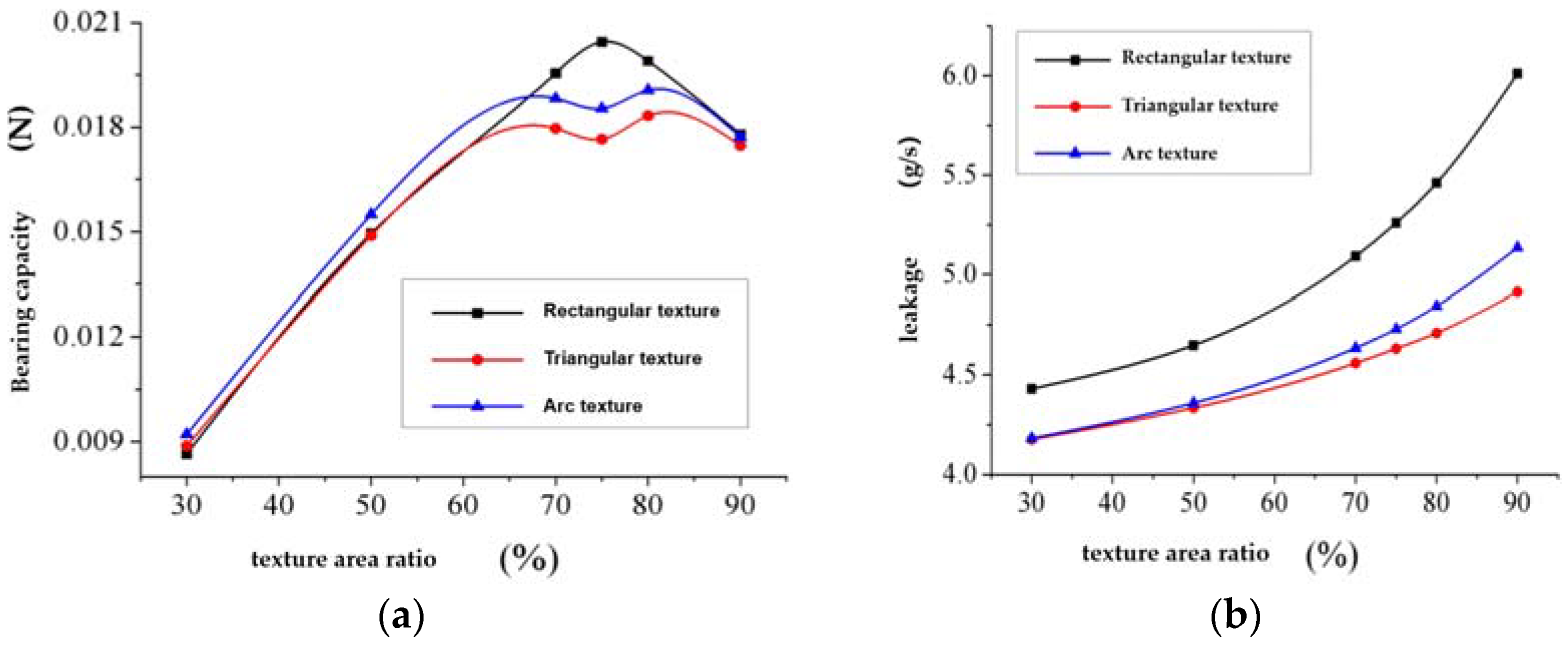
3.4. Effect of Texture Area Ratio on Bearing Capacity and Leakage
The oil film thickness is set to 10 μm, the texture depth is 10 μm, and the total length of the texture unit is 200 μm.
Figure 11 displays the analysis results of the bearing capacity and leakage for different texture area ratios.
The figure reveals that with an increase in texture area ratio, the oil film bearing capacity shows a trend of first increasing and then decreasing. After the area ratio reaches a certain value, the arrangement of textures becomes particularly dense and the distance between textures becomes smaller. When the fluid passes through the convergent region of the texture and has not been sufficiently pressurized, it reaches the divergent region of the texture, causing the pressure to sharply drop. Therefore, after the area ratio reaches a certain value, the bearing capacity becomes smaller. As the area ratio rises, the leakage rate also increases, because the volume of the leakage channel increases along with the area ratio. In addition, the leakage rate of the rectangular texture is much larger than those of the triangular and circular arc textures when the area ratio is constant.
Superior sealing performance can be achieved with larger bearing capacities, resulting in less leakage. Thus, with the grooved texture, it is most appropriate to select a triangular texture or a circular arc texture with an area ratio of about 70%.
4. Conclusions
In this paper, a fluid dynamics simulation analysis of a material surface texture treatment was conducted. The influence of texture depth, width, and area ratio of different texture types on bearing capacity and leakage was studied, and the influence of different texture parameters on the sealing performance of the sealing system was analyzed. The research background was high-end aviation equipment sealing systems, and the sealing material was PTFE. Since sealing systems often work under various temperatures and pressures, the properties of the sealing material at a certain temperature were studied through experiments to provide parameters for subsequent simulations.
According to the simulation results, although texturing treatment improves the performance of the sealing system, this does not mean that larger texture parameters result in superior sealing performance. Due to the existence of backflow, after the texture depth reaches a certain level, the hydrodynamic pressure effect is reduced. As a result, the bearing capacity of the oil film first increases and then decreases with rising texture depths. Maximum performance is achieved at a texture depth of 5–10 μm and when the texture depth exceeds 20 μm, leakage rates remain smaller than that of the smooth surface. It was established that a triangular texture with a texture depth of more than 20 μm should be selected for the groove texture. Within a certain range, the bearing capacity rises with an increase in texture width, but the leakage of the triangular texture and circular arc texture remains almost unchanged. For the groove-type texture, it is appropriate to select a triangular or arc-shaped texture with a larger width. With increasing area ratios, the bearing capacity of the oil film first rises and then falls. However, the leakage rate continues to increase and the leakage of the rectangular texture is substantially larger than that of the triangular texture or the arc texture. Thus, it is more appropriate to select the triangular texture or the arc texture with an area ratio of approximately 70% for groove textures. The leakage of the rectangular texture is larger under the same texture parameters, so the sealing effect after texture treatment is inferior to that of the triangular and circular arc textures. The values for texture depth, width, and area ratio when the sealing performance is best can be determined according to the comprehensive influence of oil film bearing capacity and leakage. Through an analysis of the influence of different texture parameters on the sealing performance of friction pairs, this paper provides a theoretical basis for the enhancement of high-end aviation equipment sealing performance by texture treatment. It also provides the possibility for the application of surface texture technology to improve the tribological properties of materials.


 ,
, 


