Proceeding Paper

Self-Assembly of Y-Shaped Polymer Brushes with Low Poly-Dispersity †

Department of Informatics, Faculty of Science, University of Jan Evangelista in Ústí nad Labem, Pasteurova 3632/15, 400 96 Ústí nad Labem, Czech Republic
*
Author to whom correspondence should be addressed.
Presented at the 3rd International Online-Conference on Nanomaterials, 25 April–10 May 2022; Available online: https://iocn2022.sciforum.net/.
Mater. Proc. 2022, 9(1), 26; https://doi.org/10.3390/materproc2022009026
Published: 22 April 2022
(This article belongs to the Proceedings of The 3rd International Online-Conference on Nanomaterials)

Abstract

:
Y-shaped polymer brushes contain two homopolymer branches attached at single grafting points. So far, monodisperse systems have mostly been studied in theory and through simulation. Introducing polydispersity can reveal new options to control the surface morphology. Here, we employ dissipative particle dynamics and vary the brush grafting density, composition of the branches, and their incompatibility to describe complex behavior of brushes at good solvent conditions. We show that scaling of the brush height obtained from simulations agrees with the theory and that usual structures, ripples, and aggregates, are shown for monodisperse systems. Finally, we observe the formation of a perforated layer instead of a ripple structure for polydisperse systems and formation of slightly asymmetric phase diagram.

1. Introduction

Y-shaped polymer brushes are composed of two incompatible homopolymer branches that are attached to the same grafting points on a substrate [1]. A variety of system parameters, including individual branch lengths, their chemical nature, grafting density, etc., lead to unique phase behavior due to the incompatibility of individual branches and due to their response to the outer environment [2]. Structures that assemble on the surface determine its mechanical, electrical, or optical properties and have great potential in a variety of modern technological applications. Mixed polymer brushes refer to systems where two or more homopolymers are randomly grafted at the same point, which not only brings about a unique phase behavior, but also issues with controlling the uniformity of grafting and reaching the long-range order [3]. Therefore, in Y-shaped brushes, the grafting point can be occupied by just one branch of each type, leading to a uniform grafting density of each homopolymer and pronounced long-range ordering. In such systems, previous investigations have shown that the self-assembly of polymers can produce layered and ripple structures and spherical micelles formed at selective solvent conditions or in a melt state. Furthermore, in nonselective solvents, a dimple structure has been observed. In an experiment, worm-like structures or nearly bicontinuous structures were formed by Y-shaped poly(tert-butyl acrylate) (PtBA)/polystyrene (PS) brushes on the surface of silica particles [4].
In addition, advances in synthesis have allowed researchers to better control and lower the polydispersity of polymers that are prepared experimentally, thus bridging the gap between the results from the theory and simulations, where monodisperse systems are mostly described, and real polymers, which are always polydisperse. In modelling, polydispersity is modeled via the Schulz−Zimm (SZ) distribution, which is commonly used for describing experimental samples [5,6]. Recently, SZ distribution was used to describe the effect of polydispersity on the structure of polymer brushes under equilibrium and non-equilibrium conditions, or to describe the shape of the density profile in polymer brushes attached to a planar solid surface [7]. In this work, we used SZ distribution to describe the effect of polydispersity on the assembly of Y-shaped brushes attached to a planar surface and dispersed under good solvent conditions.

2. Methods

2.1. Dissipative Particle Dynamics

Dissipative particle dynamics (DPD) is a well-established simulation method suitable for modeling coarse-grained models of polymer chains, and it has been used to describe the phase behavior of polymers, including the self-assembly of copolymers in melt [8], solutions, or near solid surfaces [9]. Moreover, DPD is also suitable for modeling the phase behavior of polymeric systems under non-equilibrium conditions [10].
The basic unit in DPD is called a bead, which represents a collection of atoms, molecules, or even larger part of chains. The amount of mass that is hidden within one bead is given by the coarse-graining approach [11], which is used to coarse real or fine-grained systems. Rather than coarse-graining real chains and describing the specific system, we used a generic model that can capture the general behavior of Y-shaped mixed brushes grafted onto a flat surface.

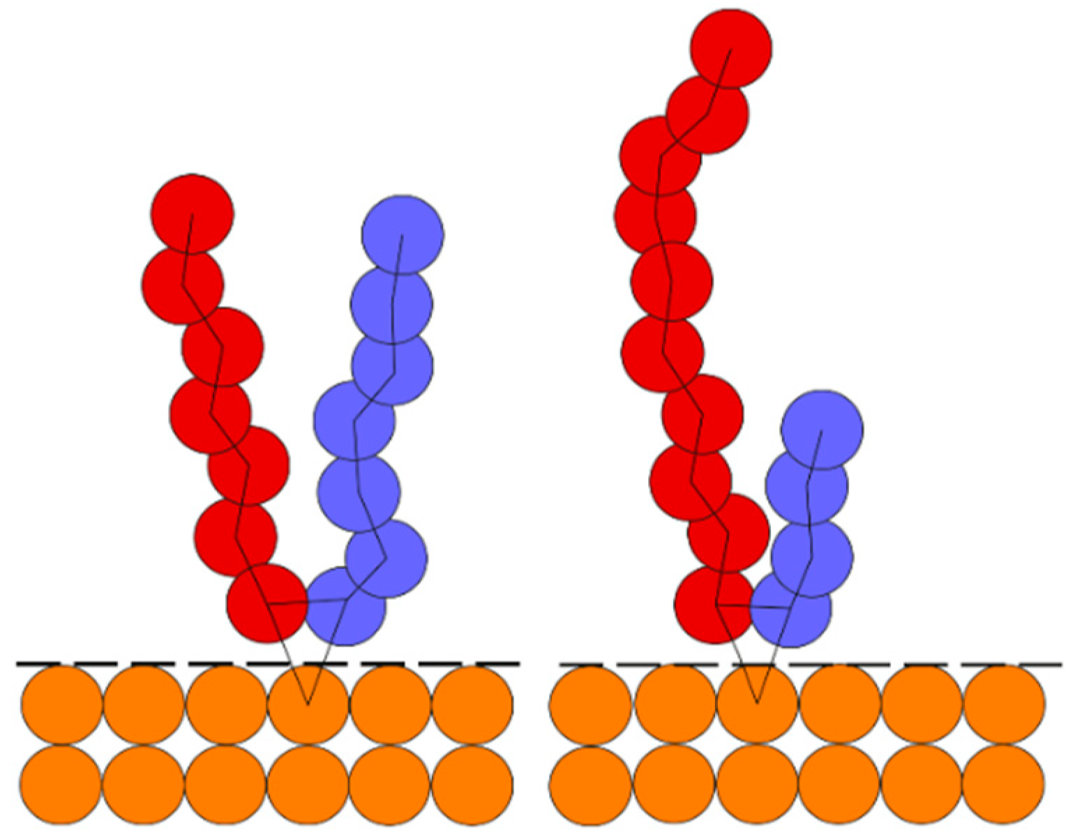
2.2. Y-Shaped Mixed Brush Grafted onto a Flat Surface

Figure 1 shows a schematic picture of a flat surface grafted using a Y-shaped mixed brush. Our coarse-grained model contains two homopolymer branches with A and B beads that are grafted by one end onto the same points on the flat surface. The grafting points are distributed randomly on the surface.
The flat surface is represented by a collection of “frozen” beads, i.e., they do not move throughout the simulation, which have a density equal to the density of the surrounding fluid. A reflective layer with bounce-back boundary conditions is placed on the interface between the surface and the fluid to avoid its unphysical penetration into the surface. The combination of a reflective layer and flat surface with a density equal to the surrounding fluid neglects the unphysical density fluctuations of the fluid near the flat surface [12].

2.3. Polydisperse Y-Shaped Mixed Brushes

We adopted the Schulz−Zimm distribution P ( N ) [5,6] to include polydispersity into our coarse-grained model. This distribution is frequently used to describe polydispersity in simulations and corresponds to the results in synthesis [13]. The delta function Γ ( k ) and two parameters, N n and k , are used to describe the distribution of chain lengths N in Equation (1).
P ( N ) = k k N k 1 Γ ( k ) N n e ( k N N n ) .
here, N n is the number averaged chain length and k is linked to the polydispersity index via the relation P D I = N w / N n = 1 + 1 / k . In the case of a monodisperse system, k , and P ( N ) transforms to the delta function, while for k 1 , the distribution of the chain lengths has an exponentially decaying shape. A branch is kept monodisperse in the rest of the paper, while the B branch has individual polydispersity P D I = { 1 ; 1 , 1 ; 1.5 ; 2.0 } to cover low and high polydisperse systems, respectively. These polydispersity indexes are also available experimentally.

3. Results

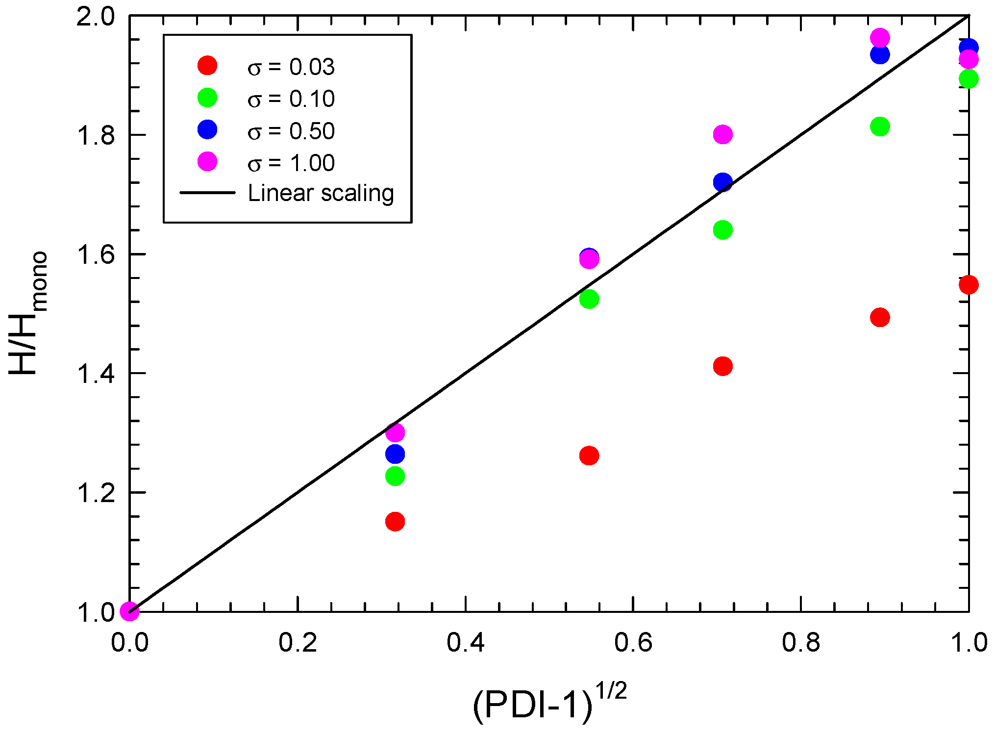
3.1. Monodisperse Y-Shaped Brush Scaling

First, we validated our simulation model. To identify the systems of interest, we performed simulations of monodisperse systems with equal compositions, f A B = 0.5 . We varied the grafting density from 0.01 up to 1.5 . Figure 2 shows the height of the brush H as a function of grafting density σ .
It can clearly be seen that systems with a low grafting density, σ 0.03 deviate from the semi-dilute polymer brush regime (SDPB) scaling (dashed line) and the brushes are fine in a mushroom regime. Increasing the σ to 0.1 leads to a crossover regime between mushroom and SDPB, while a further increase to 0.5 leads to crossover between the SDPB and CPBD regimes. A system with σ > 0.5 has all chains in CPB. The scaling behavior of the brush height in Figure 2 agrees with what has been previously published [14], and allowed us to select appropriate grafting densities for each regime and to construct their phase diagrams. In the rest of the paper, we show phase diagrams for σ = { 0.03 ; 0.1 ; 0.5 ; 1.0 } , unless otherwise stated.

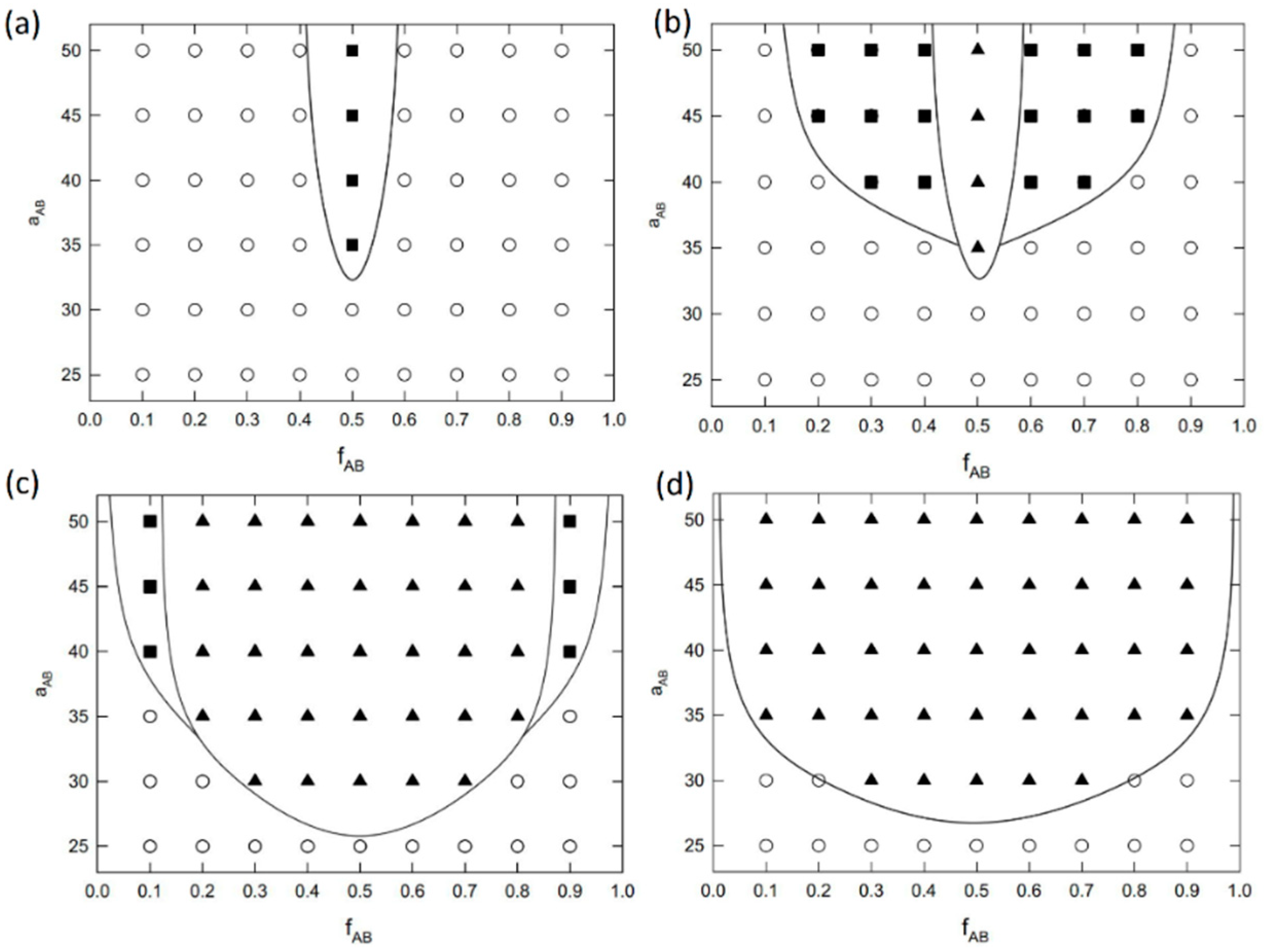
3.2. Phase Behvaior of a Monodisperse Y-Shaped Brush

Figure 3 shows complete phased diagrams of monodisperse Y-shaped copolymer brushes under good solvent conditions for both branches grafted onto flat surface. The grafting densities correspond to those selected from Figure 2, where Figure 3a shows the results for σ = 0.03 , Figure 3b for σ = 0.10 , Figure 3c for σ = 0.50 , and Figure 3d for σ = 1.0 , respectively. The phase diagrams are displayed in the a A B f A B plane, where a A B shows the incompatibility between the A and B branch in the Y-shaped brush and f A B shows the brush composition. The phase diagrams are symmetric around f A B = 0.5 , where the left part of the diagram shows the results for the A branch and the right part shows the results for the B branch of the brush.
Only aggregates that can potentially transform into different type of micelles under different solvent conditions are formed in a system with a low grafting density, σ = 0.03 , in Figure 3a, where the chains are in a mushroom regime. Here, the aggregates form mostly isolated islands that can temporarily interconnect. For f A B 0.5 cases, the stability of the aggregates is very poor and results in a disorder phase. Increasing the grafting density to the crossover value between the mushroom and SDPB regime, σ = 0.1 , as shown in Figure 3a, drives the assembly of the ripple structure at f A B = 0.5 and shifts the aggregate phase window outside the symmetric region. Although the ripple structure is stable, it is still prone to fluctuations caused by the surrounding fluid. On the other hand, aggregates that are formed close to the symmetric case seem stable enough. Again, here, we do not observe the formation of any micellar structures, as both branches of the brush are dispersed under good solvent conditions.
A further increase of the grafting density to σ = 0.5 results in the chains crossing over between SDPB and CPBD. The phase diagram in Figure 3c shows significant broadening of the ripple phase window and the aggregates are pushed to the outskirt of the phase diagram. Moreover, we see that order–disorder transition decreased from a A B = 33 to a A B around 25 , which is close to the value of χ A B = 10.5 predicted for the order–disorder transition for the pure diblock copolymer melt. The systems with the highest grafting density, σ = 1.0 , show only the ripple phase, and no other type of structure is observed.

3.3. Polydisperse Y-Shaped Brush Scaling

To set up proper minimum and maximum chain lengths in the Schulz–Zimm distribution and to test the validity of the polydisperse set of chains generated, we first compared the scaling behavior of polydisperse homopolymer brush H scaled by the corresponding monodisperse brush H m o n o . Figure 4 shows the scaled brush height H / H m o n o as a function of ( P D I 1 ) 1 / 2 for all of the grafting densities considered in this study. We measured the scaled brush height in systems with P D I = { 1.1 , 1.3 , 1.5 , 1.8 , 2.0 } . The solid black line in the figure shows the linear scaling predicted by theory in the following form
H / H m o n o = 1 + α ( P D I 1 ) 1 / 2 ,
where α 1.0 [7] and color points mark our simulation results. We see that our systems follow theoretical predictions in the case where the minimum and maximum chain lengths in our system are 5 and 6 N , respectively. These settings are used in the rest of the paper for all polydisperse systems and determine the size of the simulation box. Moreover, we can see that scaling is achieved for chains with a medium and high grafting density with chains in the SDPB or CPBD regime (see Figure 2 for details). Chains at σ = 0.03 that are in mushroom regime have α 0.55 .

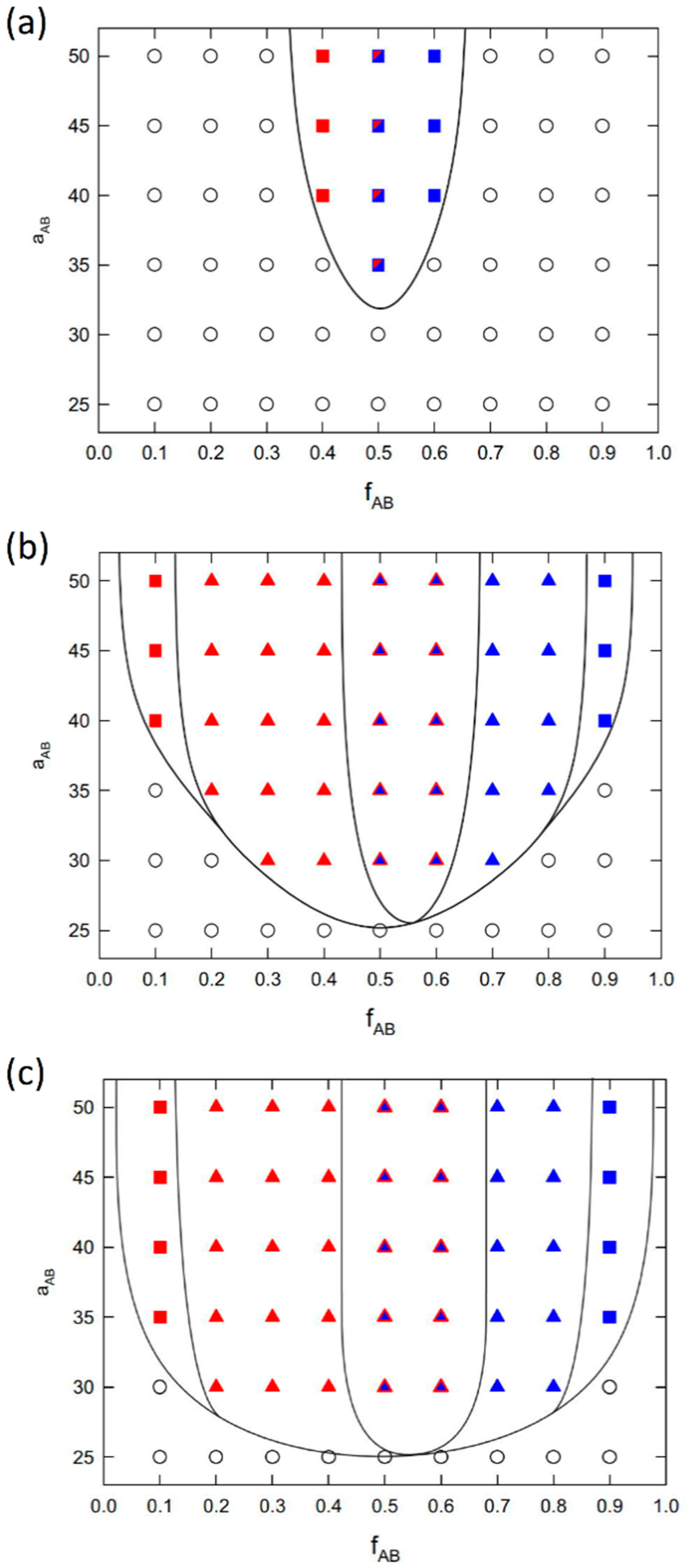
3.4. Phase Behavior of a Polydisperse Y-Shaped Brush

Figure 5 shows the phase behavior of polydisperse brushes with a low polydispersity P D I = 1.1 . The comparison with monodisperse systems in Figure 3 reveals that even a small polydispersity for the B branch influences the assembly in the system and the surface morphology. First, we see that no assembly is observed in the case of sparsely grafted Y-shaped brushes (the σ = 0.03 phase diagram is not shown here) and the formation of ripple phase in systems with σ = 0.1 is suppressed where we see only the aggregates. More importantly, in a system with a medium ( σ = 0.5 ) to high grafting density ( σ = 1.0 ), we see the formation of a perforated layer (PL) of A instead of the ripple structure formed in the monodisperse system. The PL phase extends further to f A B = 0.6 . The reason for this is that it lies on a long polydisperse B branches that stick out from the B ripple phase located close to the surface. These chains then penetrate through the A phase to the surrounding fluid. Such long chains are not in monodisperse systems where all the B branches are, where f A B > 0.5 for the branches shorter than A . Therefore, a similar behavior was not observed in the case of f B A > 0.5 , where monodisperse A branches are much shorter and are not able to penetrate the B layer. For this reason, the phase diagrams of polydisperse systems are no longer symmetric around f B A = 0.5 .
Further increasing the P D I to 1.5 and 2.0 , figures not shown here, moves the barrier between the order–disorder transition above systems with σ = 0.1 . Moreover, the formation of the PL phase is more pronounced, ranges from 0.5 up to 0.7 , and occupies a large portion of the B phase window, where in a monodisperse system, we see a compact A layer above the B ripple phase. Finally, Figure 6 shows the simulation snapshots of the ripple and PL phase formed in monodisperse and polydisperse ( P D I = 1.1 ) systems with σ = 0.5 and f A B = 0.5 .

4. Discussion

In this work, we employed coarse-grained modelling and dissipative particle dynamics to describe the phase behavior of polydisperse Y-shaped brushes grafted to a flat surface and dispersed under good solvent conditions. In our polydisperse brush, the A branch was kept monodisperse, while B branch possessed different polydispersity that fits the experimentally achievable values. First, we validated our model by fitting the scaling behavior of a monodisperse system as a function of the grafting density. We showed that our model successfully captured all scaling regimes from mushroom to concentrated polymer brushes, and we were able to set proper grafting densities in these regimes for further simulations. Then, we performed a series of simulations to describe the phase behavior of monodisperse systems and showed that only aggregates and ripple structures were formed, which agrees with previously studied simulations and with theoretical predictions. Furthermore, we considered the Schulz−Zimm distribution to include polydispersity to the B branch of the Y-shaped brush. We showed that even a small polydispersity shifted the order–disorder transition to higher grafting densities. More importantly, we showed that starting at P D I = 1.1 , the ripple structure was replaced by a perforated layer and that its phase window extended more when increasing the PDI up to 2, where only ripple and perforated layers were observed. Finally, we showed that manipulating the polydispersity of branches in Y-shaped brushes can lead to interesting phase behavior, and that combinations of polydispersity can offer additional parameters to control the morphology of a functionalized surface.

Author Contributions

P.F. and Z.P. performed the simulations. P.F. was responsible for writing the software for analyzing the trajectories and for data curation. Z.P. wrote and edited the manuscript. All authors have read and agreed to the published version of the manuscript.

Funding

Z.P. acknowledges the support from ERDF/ESF project “UniQSurf-Centre of biointerfaces and hybrid functional materials” (no. CZ.02.1.01/0.0/17_048/0007411). Z.P. and P.F. both acknowledge the assistance provided by the Technology Agency of the Czech Republic, under the project Metamorph, project no. TO01000329.

Institutional Review Board Statement

Not applicable.

Informed Consent Statement

Not applicable.

Data Availability Statement

Not applicable.

Conflicts of Interest

The authors declare no conflict of interest.

References

  1. Hou, W.; Liu, Y.; Zhao, H. Surface Nanostructures Based on Assemblies of Polymer Brushes. ChemPlusChem 2020, 85, 998–1007. [Google Scholar] [CrossRef] [PubMed]
  2. Li, M.; Pester, C.W. Mixed Polymer Brushes for “Smart” Surfaces. Polymers 2020, 12, 1553. [Google Scholar] [CrossRef] [PubMed]
  3. Yin, Y.; Jiang, R.; Wang, Z.; Li, B. Influence of Grafting Point Distribution on the Surface Structures of Y-Shaped Polymer Brushes in Solution. Langmuir 2016, 32, 7467–7475. [Google Scholar] [CrossRef] [PubMed]
  4. Zhao, B.; Zhu, L. Nanoscale Phase Separation in Mixed Poly(tert-butyl acrylate)/Polystyrene Brushes on Silica Nanoparticles under Equilibrium Melt Conditions. Am. Chem. Soc. 2006, 128, 4574–4575. [Google Scholar] [CrossRef] [PubMed]
  5. Schulz, G.V. Uber Die Kinetik Der Kettenpolymerisationen. Phys. Chem. 1939, 43, 25–46. [Google Scholar] [CrossRef]
  6. Zimm, B. Apparatus and methods for measurement and interpretation of the angular variation of light scattering; preliminary results on polystyrene solutions. J. Chem. Phys. 1948, 16, 1099–1116. [Google Scholar] [CrossRef]
  7. Qi, S.H.; Klushin, L.I.; Skvortsov, A.M.; Schmid, F. Polydisperse Polymer Brushes: Internal Structure, Critical Behavior, and Interaction with Flow. Macromolecules 2016, 49, 9665–9683. [Google Scholar] [CrossRef]
  8. Posel, Z.; Lísal, M.; Brennan, J.K. Interplay between microscopic and macroscopic phase separations in ternary polymer melts: Insight from mesoscale modelling. Fluid Phase Equilib. 2009, 283, 38–48. [Google Scholar] [CrossRef]
  9. Posel, Z.; Posocco, P. Tuning the Properties of Nanogel Surfaces by Grafting Charged Alkylamine Brushes. Nanomaterials 2019, 9, 1514. [Google Scholar] [CrossRef]
  10. Posel, Z.; Svoboda, M.; Coray, C.; Lisal, M. Flow and aggregation of rod-like proteins in slit and cylindrical pores coated with polymer brushes: An insight from dissipative particle dynamics. Soft Matter 2017, 13, 1634–1645. [Google Scholar] [CrossRef] [PubMed]
  11. Brin, E.; Algaer, E.A.; Ganguly, P.; Li, C.; Rodriguez-Ropero, F.; Van der Vegt, N.F.A. Systematic coarse-graining methods for soft matter simulations—A review. Soft Matter 2013, 9, 2108–2119. [Google Scholar] [CrossRef]
  12. Pivkin, I.V.; Karniadakis, G.E. A new method to impose no-slip boundary conditions in dissipative particle dynamics. J. Comput. Phys. 2005, 207, 114–128. [Google Scholar] [CrossRef]
  13. Turgman, C.S.; Srogl, J.; Kiserow, D.; Genzer, J. On-demand degrafting and the study of molecular weight and grafting density of Poly(methyl methacrylate) brushes on flat silica substrates. Langmuir 2015, 31, 2372–2381. [Google Scholar]
  14. Gao, H.M.; Liu, H.; Lu, Z.Y.; Sun, Z.Y.; An, L.J. The structures of thin layer formed by microphase separation of grafted Y-shaped block copolymers in solutions. J. Chem. Phys. 2013, 138, 224905–224914. [Google Scholar] [CrossRef]
Figure 1. Coarse-grained model of Y-shaped mixed brushes. Left: Y-shaped brush with symmetric distribution. Right: The asymmetric distribution of A (red) and B (blue) chain lengths. Orange beads represent frozen wall beads that do not move throughout the simulation and the dashed line is a reflective layer with bounce-back boundary conditions that avoids the penetration of the surrounding fluid (not shown here) into the solid surface.
Materproc 09 00026 g001
Figure 2. Brush height H as a function of the grafting density σ for Y-shaped mixed brushes with a symmetric composition f A B = 0.5 . The dashed line indicates scaling of a semi-dilute polymer brush (SDPB) regime, while the dotted line stands for the concentrated polymer brush (CPB) regime.
Materproc 09 00026 g002
Figure 3. Phase diagrams of monodisperse Y-shaped mixed brushes under good solvent conditions grafted onto a flat surface with (a) σ = 0.03 , (b) σ = 0.10 , (c) σ = 0.50 , and (d) σ = 1.0   chains / unit   area grafting density. Phase diagrams are shown in the a A B f A B plane, where a A B shows the incompatibility between the A and B branch in a Y-shaped brush and f A B shows the composition of the branches in the brush. Symbols: disordered systems (open circle), aggregates (filled square), and ripple structure (filled triangle). The solid line shows the approximate boundaries between the different phases.
Materproc 09 00026 g003
Figure 4. Brush height of the polydisperse homopolymer brush H scaled by the corresponding monodisperse value H m o n o , as a function of the polydispersity index P D I = N w / N n . The solid line indicates the linear scaling predicted by theory and the colored points are the simulation results for the different grafting densities.
Materproc 09 00026 g004
Figure 5. Phase diagrams of polydisperse Y-shaped mixed brushes with P D I = 1.1 under good solvent conditions grafted onto a flat surface with (a) σ = 0.10 , (b) σ = 0.50 , and (c) σ = 1.0   chains / unit   area grafting density. Phase diagrams are shown in the a A B f A B plane, where a A B shows the incompatibility between the A and B branches in a Y-shaped brush and f A B shows the composition of the branches in the brush. Symbols: disordered systems (open circle), aggregates (filled square), and ripple structure (filled triangle). The solid line shows the approximate boundaries between the different phases. Red shows the structures formed by the A branch and blue shows the B branch. The half red, half blue square indicates that both types form aggregates, and the blue triangle with a red edge line indicates a perforated layer.
Materproc 09 00026 g005
Figure 6. Simulation snapshots of a (a) ripple phase formed in a monodisperse system and (b) a perforated layer formed in a polydisperse system with P D I = 1.1 . Both systems have σ = 0.5 and f A B = 0.5 . Red indicates the A branch of a Y-shaped brush. The polydisperse B branch is omitted for clarity.
Materproc 09 00026 g006
Publisher’s Note: MDPI stays neutral with regard to jurisdictional claims in published maps and institutional affiliations.

