Proceeding Paper

The Non-Linear Behavior of Mixed Reinforced Concrete–Steel Frames under Strong Earthquakes †

by
Paraskevi K. Askouni
1,* and
George A. Papagiannopoulos
2
1
Department of Civil Engineering, University of Patras, 26504 Patras, Greece
2
School of Science and Technology, Hellenic Open University, 26335 Patras, Greece
*
Author to whom correspondence should be addressed.
Presented at the 1st International Online Conference on Buildings, 24–26 October 2023; Available online: https://iocbd2023.sciforum.net/.
Eng. Proc. 2023, 53(1), 15; https://doi.org/10.3390/IOCBD2023-15197
Published: 8 November 2023
(This article belongs to the Proceedings of The 1st International Online Conference on Buildings)

Abstract

:
Mixed building frames constructed using reinforced concrete (RC) in the lower stories and structural steel in the higher ones meet great scientific interest as forming a common and often constructed building type. However, the current seismic regulations do not provide special guidelines for the aforementioned vertically mixed building type, but only for building frames constructed with the same material throughout. In addition, a small number of respective works in the literature can be found, thus underlining the need for the thorough examination of the nonlinear response of mixed reinforced concrete and structural steel frames subjected to strong ground excitations. Due to space limitations, selected cases of mixed RC–steel 3D frames are analyzed here via nonlinear dynamic analysis under selected intense earthquakes, considering appropriate nonlinear mechanical models for structural elements. A comparison of nonlinear response results is performed for two considered connection types of the steel part on the RC part, which are called “fixed” and “fixed-pinned” connections here. In this way, the nonlinear response of mixed-frame cases is studied under extreme ground motions, towards the utmost unfavorable conditions. Selected comparative nonlinear response results and plots are presented to estimate the behavior of mixed frames. Qualitative remarks arise from the current described investigation, resulting in practical suggestions for the design enhancement of mixed buildings, available for the upgrade of current codes.

1. Introduction

The building case involving a steel part added on a reinforced concrete (RC) one, called here a “mixed” building, tends to be found oftentimes in usual constructions. However, the current seismic regulations refer to the design of structures made with the same material, such as Eurocode 8 (EC8) [1], neglecting the mixed structural type, which is frequently seen in construction practice. The current research involves mixed building cases, where the steel stories have the same in-plan dimensions as the lower RC part, neglecting the case of a secondary structure added on a primary one [2] as a result of the additional structure being significantly smaller and lighter than the originally constructed one. The current investigation deals with the construction case of upper steel-added stories with the same size in plan as the lower RC part, consequently adding a significant mass and weight on the latter.
This work investigates solely the vertically mixed RC–steel frames, where the structural material of each story element is either reinforced concrete or steel, excluding a combination of these in the same story. Emphasis is given to the difference between the studied vertically mixed building cases from the composite buildings, which are characterized by the cooperation of reinforced concrete and steel on the same element section.
Although great practical attention is paid to vertically mixed RC–steel buildings, a shortage of relative scientific research exists concerning their design and behavior under intense ground excitation, while the focus is concentrated on “moment-resisting frames” (“MRFs”) [3]. In the meantime, the current design seismic code [1] provides different values of the damping ratio as 5% for RC structures and 2% for steel ones, neglecting giving one value for mixed frames which is investigated by a few works in the literature, e.g., by Sivandi-Pour et al. [4]. The use of a uniform damping ratio value is necessary for the performance of non-linear dynamic analysis, although not provided for mixed frames by [1].
The present paper aims to present the preliminary results of an ongoing investigation on the seismic behavior of mixed RC–steel buildings, which has a great scientifical interest as not included in the guidelines of the current seismic code [1]. Due to space limitations, selected cases of mixed symmetric frames are considered for analysis and discussion.

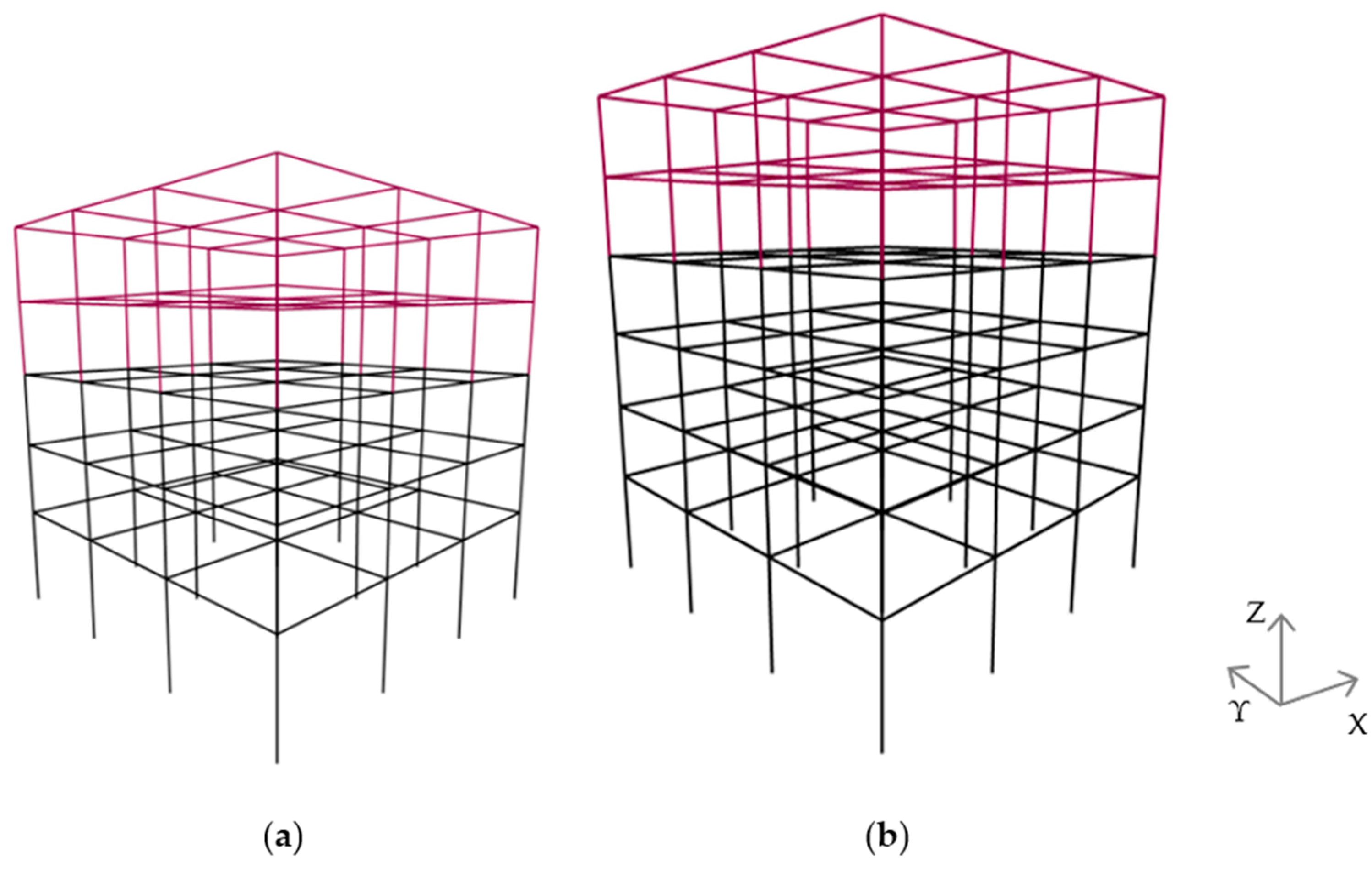
2. Mixed RC–Steel Building Cases and Analysis

This work examines five- and six-story mixed 3D frames (Figure 1), referring to common medium-rise buildings. The lower stories, shown in black color (Figure 1), are constructed with concrete C25/30 reinforced with B500c [5], while the two upper ones, shown in crimson color, are constructed with structural steel of S355 grade [6], forming mixed frames with a square plan of 15 × 15 m2. The bottom story has a 4.0 m height, and the upper one has a 3.0 m height. The RC or composite story slabs—respectively, for RC or steel columns—have 0.15 m thickness and act as rigid diaphragms.
The mixed frames are designed according to current regulations [1,5,6] as ordinary buildings, with corresponding combined loadings [7], with 30% rule and 5% accidental eccentricity [1], for a zone ground acceleration of 0.36 g [1], 5% viscous damping ratio, C soil type, and a neglect of possible ground deformability [1]. The behavior factor of the mixed frames is 3.9 and 4.0 for RC and steel parts for the medium-ductility class [1]. The orientation of steel vertical elements is designed as in Figure 2 to form a strong perimetrical frame. The detailing of the mixed frames is shown in Table 1.
Regarding the support of the steel part upon the RC one, the following two cases are examined: a “fixed” [8] support of the steel vertical elements in the two horizontal directions of the mixed frames and a “fixed-pinned” [8] support of the steel vertical elements, i.e., fixed in the minor axis of the cross-section and pinned in the major corresponding axis. This distinction refers to the two extreme cases similar to [8]. Following the research of [4], a uniform value of damping ratio is calculated for each frame, calculated as 2.31% for the five-story one and 2.14% for the six-story one [4].
The dynamic analyses are performed using RUAMOKO software [9] under strong earthquakes downloaded from [10] as presented in Table 2, where for each earthquake there are listed the “name, location, year, moment magnitude (Mw)” [8] and the “peak ground acceleration (PGA)” [8]. As found in various research works, e.g., Refs. [3,8], the direction of the ground motion may influence the structural response. In the current research, the angles of the ground excitations are considered along the basic horizontal axes (Figure 1), i.e., 0° and 90°. The nonlinear behavior of structural RC and steel elements is simulated via the application of point hinges at their ends according to ASCE 41-17 [11].

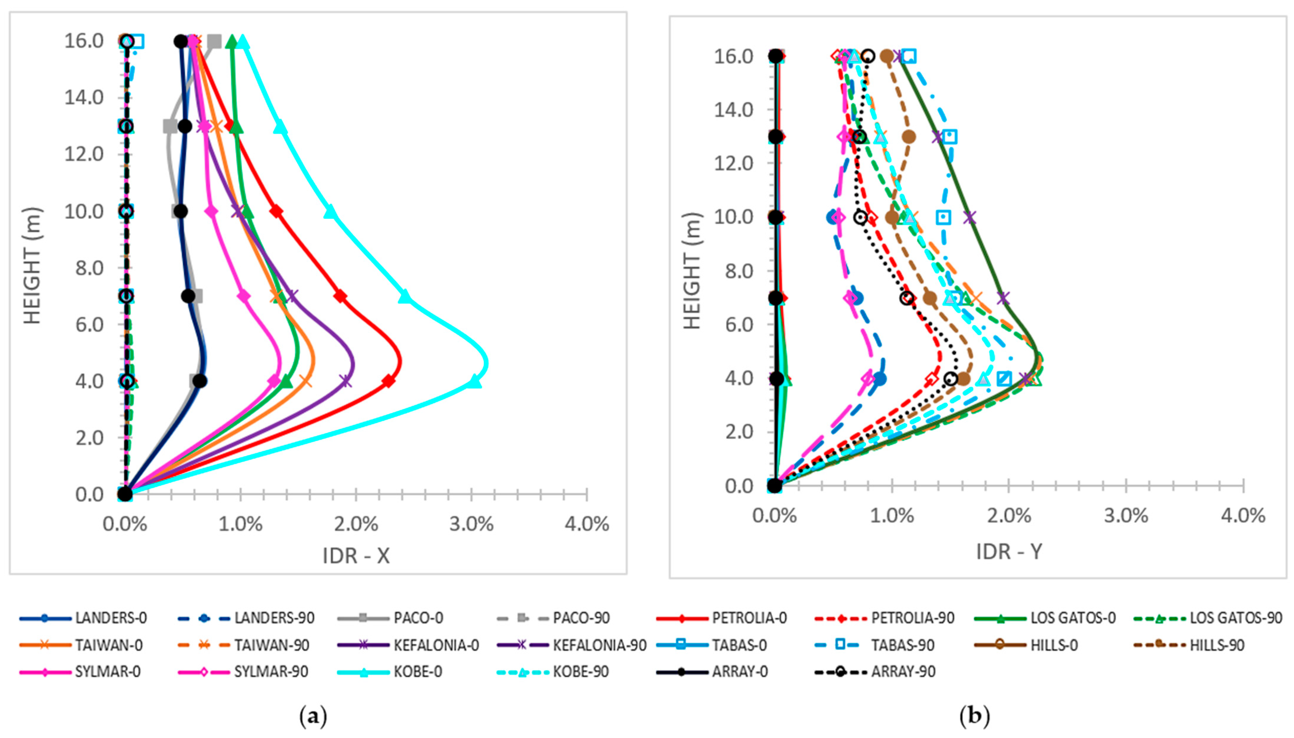
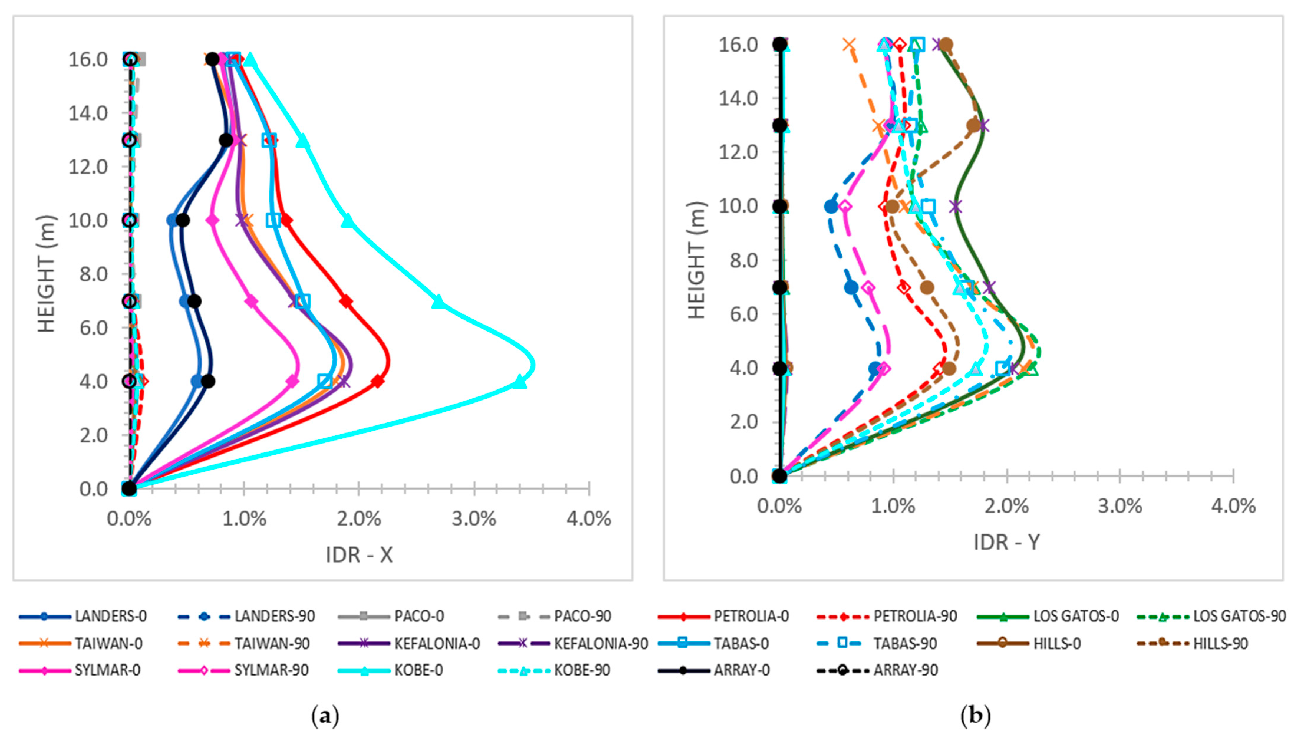
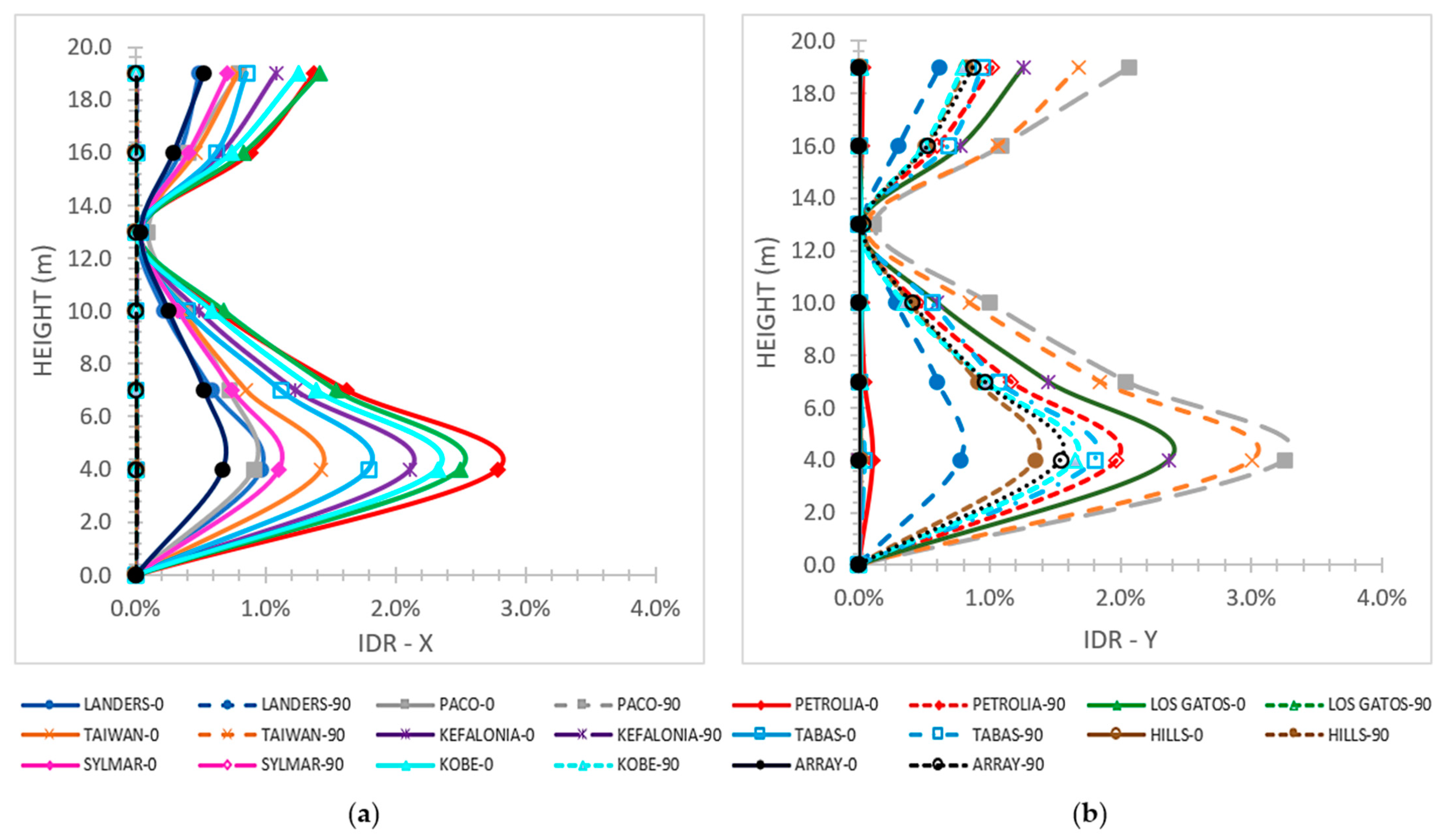
3. Results and Discussion

Selected charts of the NLTH analyss results are presented in the following section, regarding the maximum interstory drift ratio (IDR) on the horizontal axes, X and Y. Each earthquake name is followed by 0 or 90, referring to the corresponding incidence angle of 0° or 90°. The presented IDR charts are compared to the limits of the performance levels of [12] for RC or steel buildings, which are 0.5% for the “Fully Operational (FO)” level [12], 1.5% for the “Immediate Occupancy (IO)” stage [12], 2.5% for the “Life Safety (LS)” stage [12], and 3.8% for the “Near Collapse (NC)” stage [12].
For the five-story mixed frame with the fixed support of the steel structure on the RC stories (Figure 3), the maximum IDR values are presented at the top of the first story as 0.03 on the X axis and 0.022 on the Y axis; these are inside the NC level for the X axis and LS level for the Y axis, respectively [12].
For the fixed–pinned connection at the five-story mixed building (Figure 4), the greatest IDR values are 3.4% on the X axis and 2.1% on the Y axis, and at the top of the first story, inside the NC level for the X axis and the LS level for the Y axis [12], respectively. However, in Figure 4, we omitted the plotlines of the San Fernando and Loma Prieta earthquakes with 0° on the X axis, and the San Fernando and Imperial Valley earthquakes with 90° on the Y axis, as a result of extreme IDR arithmetic values much higher than the restrictions of [12].
For the fixed support at the six-story mixed frame (Figure 5), the greatest IDR values are noted at the top of the first story as 2.8% on the X axis and 3.3% on the Y axis, which are both inside the NC level [12]. At the building top (Figure 5), the maximum IDR values are 1.4% on the X axis and 2.1% on the Y axis, which are below the LS limit [12].
For the fixed–pinned support of the six-story mixed frame (Figure 6), the biggest IDR values at the top of the first story are 2.8% on the X axis and 3.0% on the Y axis, within the NC level [12]. In Figure 6a, extreme values of IDR on the Y axis are observed for the Tabas excitation with an incidence angle of 90°, so this plotline is omitted. At the building top, the maximum IDR values are 1.5% on the X axis and 2.1% on the Y axis, which are below the limit of the LS level [12].
At the interconnection of the steel part on the RC one, very small IDR values are observed for the fixed connection, indicatively mentioned as 0.04% on the X axis and 0.05% on the Y axis (Figure 5). Similarly, for the fixed–pinned connection, at this interconnection, the observed IDR values are close to 0.3% for both axes (Figure 6), which are almost ten times higher than the corresponding values for the fixed connection (Figure 5), while all these values are within the FO limit level [12].

4. Conclusions

This research explores the nonlinear behavior of selected mixed building cases under strong ground motions, considering two connections of the steel part on the RC one, due to the negligence of the current seismic regulations to provide specific design instructions for them. The numerical results of the NLTH analyses are compared to the limits of a current code [12], leading to the following conclusions, which apply to mixed frames similar to the currently considered cases.
  • The fixed–pinned support of the steel stories upon the RC structure results in more failures of the mixed frames, contrasted with the fixed support.
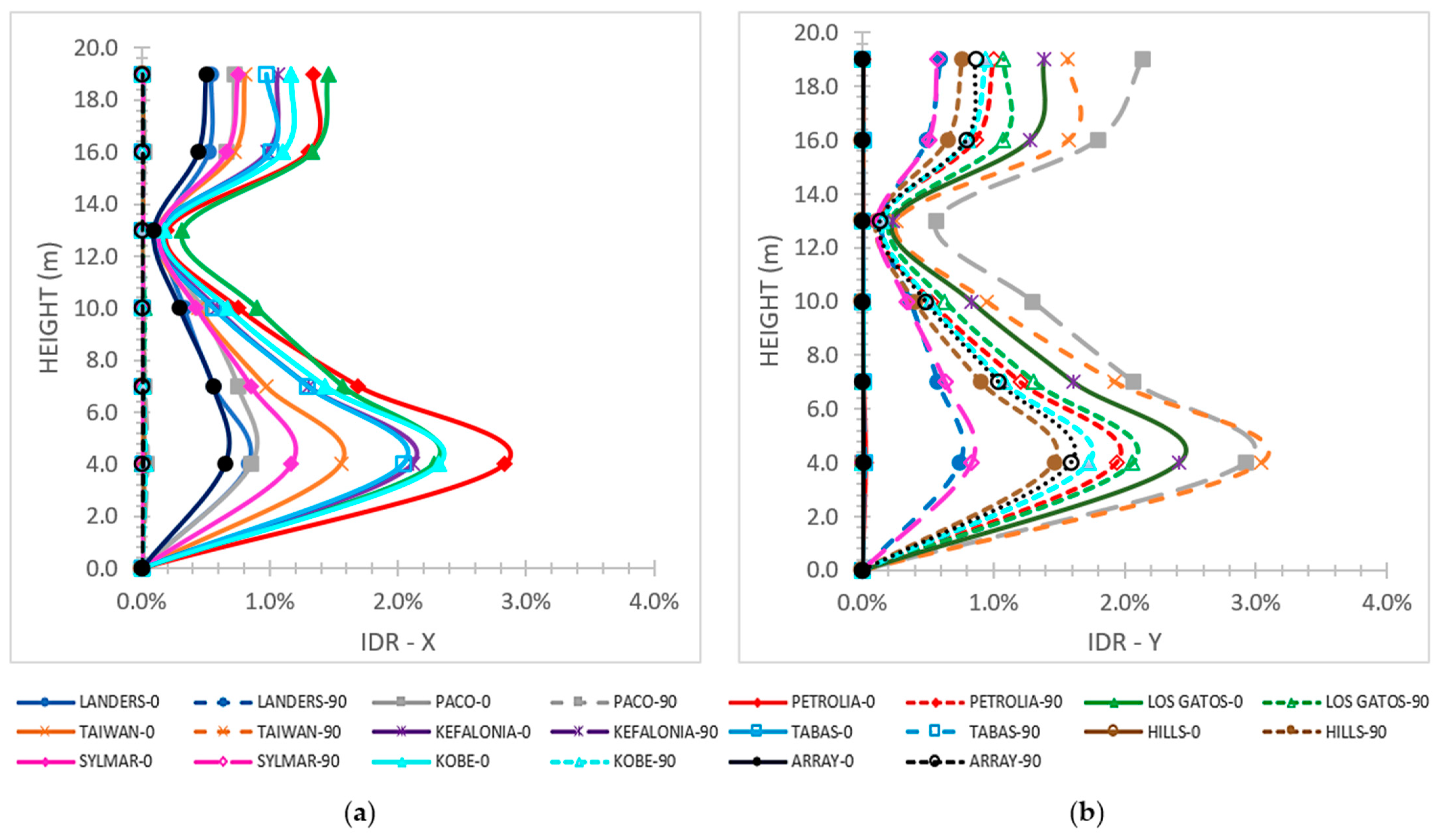
  • The IDR values are often smaller for the fixed–pinned support than for the fixed one.
  • The IDR values are, in general, within the permissible range limits of the performance levels of the considered regulation, except for the cases of building failures.
  • The steel elements tend to have almost elastic behavior, as shown by the low IDR response values of the steel stories. However, the RC structural elements show an intense nonlinear behavior, as observed from the great IDR response values of the RC stories.
Symmetrical or almost symmetrical mixed 3D frames, probably with more stories and/or bay bans, through avoiding extreme alterations in the distribution of mass and stiffness, are expected to exhibit seismic behavior under strong ground motions, similar to the one recognized in the current work. The selected analyzed mixed-frame cases refer to common buildings to give useful remarks for common construction practice.
The findings of the current investigation do not include the non-linear behavior of mixed RC–steel buildings with in-plan or in-height asymmetry, or with notable differences in the stiffness and mass distribution plan-wise or height-wise, which should belong to possible future research. Also, the two extreme supporting conditions of the steel part upon the RC one are considered in the current non-linear dynamic analyses, leaving aside the effect of more intermediate support types on the seismic structural response for future investigation.
If mixed RC–steel buildings, from the viewpoint of different construction materials, tend to become more widely applicable in common construction practice and in combination with the current investigation’s conclusions, it appears that future seismic codes should contain detailed instructions for the seismic design of mixed RC–steel buildings.

Author Contributions

P.K.A. and G.A.P. have equally contributed to the conception, design, and execution of this study. The final paper has been critically revised and accepted by P.K.A. and G.A.P. All authors have read and agreed to the published version of the manuscript.

Funding

This research received no external funding.

Institutional Review Board Statement

Not applicable.

Informed Consent Statement

Not applicable.

Data Availability Statement

Data are contained within this paper.

Conflicts of Interest

The authors declare no conflict of interest.

References

  1. Eurocode 8 (EC8); Design of Structures for Earthquake Resistance—Part 1-1: General Rules, Seismic Actions and Rules for Buildings; European Committee for Standardization (CEN): Brussels, Belgium, 2004.
  2. Villaverde, R. Fundamental Concepts of Earthquake Engineering; CRC Press: Boca Raton, FL, USA, 2009. [Google Scholar]
  3. Maley, T.J.; Sullivann, T.J.; Pampanin, S. Issues with the seismic design of mixed MRF Systems. In Proceedings of the 15th World Conference on Earthquake Engineering, Lisboa, Portugal, 24–28 September 2012; Available online: http://www.iitk.ac.in/nicee/wcee/article/WCEE2012_4043.pdf (accessed on 3 May 2021).
  4. Sivandi-Pour, A.; Gerami, M.; Khodayarnezhad, D. Equivalent modal damping ratios for non-classically damped hybrid steel concrete buildings with transitional storey. Struct. Eng. Mech. 2014, 50, 383–401. [Google Scholar] [CrossRef]
  5. Eurocode 2 (EC2); Design of Concrete Structures—Part 1-1: General Rules and Rules for Buildings; European Committee for Standardization (CEN): Brussels, Belgium, 2004.
  6. Eurocode 3 (EC3); Design of Steel Structures—Part 1-1: General Rules and Rules for Buildings; European Committee for Standardization (CEN): Brussels, Belgium, 2009.
  7. Eurocode 1 (EC1); Actions on Structures—Part 1-1: General Actions, Densities, Self-Weight, Imposed Loads for Buildings; European Committee for Standardization (CEN): Brussels, Belgium, 2001.
  8. Askouni, P.K.; Papagiannopoulos, G.A. Seismic Behavior of a Class of Mixed Reinforced Concrete-Steel Buildings Subjected to Near-Fault Motions. Infrastructures 2021, 6, 172. [Google Scholar] [CrossRef]
  9. Carr, A.J. Ruaumoko 3D: Program for Inelastic Dynamic Analysis. Theory and User Guide to Associated Programs; Department of Civil Engineering, University of Canterbury: Christchurch, New Zealand, 2009. [Google Scholar]
  10. Center for Engineering Strong Motion Data. Available online: www.strongmotioncenter.org (accessed on 3 May 2021).
  11. ASCE 41-17; Seismic Evaluation and Retrofit of Existing Buildings. American Society of Civil Engineers: Reston, VA, USA, 2017.
  12. SEAOC. Recommended Lateral Force Requirements and Commentary, 7th ed.; Structural Engineers Association of California: Sacramento, CA, USA, 1999. [Google Scholar]
Figure 1. (a) Five- and (b) six-story mixed RC–steel 3D frames under study (lower RC stories with black color and higher steel stories with crimson color) with a global coordinate system.
Engproc 53 00015 g001
Figure 2. In-plan orientation of steel columns.
Engproc 53 00015 g002
Figure 3. Interstory drift ratio on (a) X and (b) Y axes for the 5-story frame for the fixed support of the steel structure on the RC stories.
Engproc 53 00015 g003
Figure 4. Interstory drift ratio on (a) X and (b) Y axes for the 5-story frame for the fixed-pinned support of the steel structure on the RC stories.
Engproc 53 00015 g004
Figure 5. Interstory drift ratio on (a) X and (b) Y axes for the 6-story frame for the fixed support of the steel part on the RC one.
Engproc 53 00015 g005
Figure 6. Interstory drift ratio on (a) X and (b) Y axes for the 6-story frame for the fixed-pinned support of the steel structure on the RC stories.
Engproc 53 00015 g006
Table 1. Detailing of the considered mixed buildings.
Five-Story BuildingColumnsBeams
Story NumberHeight (m)MaterialsSection (cm/cm)Longitudinal ReinforcementVertical
Reinforcement
Section (cm/cm)Longitudinal ReinforcementVertical
Reinforcement
14RC70/708Φ22 + 16Φ20Φ8/1025/708Φ20 + 8Φ16Φ8/10
23RC70/7016Φ20Φ8/1025/708Φ20 + 8Φ10Φ8/10
33RC70/708Φ20 + 8Φ10Φ8/1025/608Φ18Φ8/10
43steelHEΒ 500IPE 360
53steelHEΒ 500IPE 300
Six-Story BuildingColumnsBeams
Story NumberHeight (m)MaterialsSection (cm/cm)Longitudinal ReinforcementVertical ReinforcementSection (cm/cm)Longitudinal ReinforcementVertical Reinforcement
14RC70/7032Φ20Φ8/1025/708Φ20 + 8Φ10Φ8/10
23RC70/7016Φ20Φ8/1025/708Φ18Φ8/10
33RC70/7016Φ20Φ8/1025/708Φ18Φ8/10
43RC70/7016Φ20Φ8/1025/708Φ18Φ8/10
53steelHEA 500IPE 400
63steelHEA 500IPE 400
Table 2. Earthquakes considered in the current analyses.
Earthquake, Location, YearName for ChartsMwPGA (g)
San Fernando, USA, 1971PACO6.61.17/1.08
Tabas, Iran, 1978TABAS7.10.93/1.10
Imperial Valley, USA, 1979ARRAY6.50.34/0.46
Superstition Hills, USA, 1987HILLS6.50.45/0.38
Loma Prieta, USA, 1989LOS GATOS7.00.56/0.61
Cape Mendocino, USA, 1992PETROLIA6.90.66/0.59
Landers, USA, 1992LANDERS7.30.81/0.73
Northridge, USA, 1994SYLMAR6.70.37/0.58
Kobe, Japan, 1995KOBE6.90.61/0.62
Chi-Chi, Taiwan, 1999TAIWAN7.60.50/0.36
Kefalonia, Greece, 2014KEFALONIA6.10.67/0.60
Disclaimer/Publisher’s Note: The statements, opinions and data contained in all publications are solely those of the individual author(s) and contributor(s) and not of MDPI and/or the editor(s). MDPI and/or the editor(s) disclaim responsibility for any injury to people or property resulting from any ideas, methods, instructions or products referred to in the content.

