Proceeding Paper

Design of Three-Level NPC AC/DC Bidirectional Converter Using Model Predictive Controller for DC Bus Voltage Stability of Subway †

School of Electrical Engineering, Southwest Jiaotong University, Chengdu 611756, China
*
Author to whom correspondence should be addressed.
Presented at the 8th International Electrical Engineering Conference, Karachi, Pakistan, 25–26 August 2023.
Eng. Proc. 2023, 46(1), 37; https://doi.org/10.3390/engproc2023046037
Published: 28 September 2023
(This article belongs to the Proceedings of The 8th International Electrical Engineering Conference)

Abstract

:
In this paper, the model predictive control technique is proposed to control the voltage balancing for the subway train 1500 V DC system for variable loads. This paper compares the conventional neutral point clamped converter (NPC) using the control technique of a PI controller with model predictive control in variable load conditions. MPC enhances the stability of the system during variable loads in comparison with the conventional technique. Consequently, the suggested control technique using MPC can maintain the DC bus output voltage dynamics at variable loads for the subway. Simulation results are provided to demonstrate the accuracy of the DC bus output voltage dynamics for the proposed control method.

1. Introduction

The transportation industry’s growing reliance on high-power systems and equipment has highlighted the two-level converter’s drawbacks [1]. When utilized in high-power systems, two-level converters experience switching losses, leading to a decrease, as the switching frequency rises, in power effectiveness. Additionally, the circuit’s structural qualities cause an increase in the amount of stress that each switch must withstand, resulting in a reduced device lifetime [2]. As a result, more frequent converter maintenance and repair are necessary, related to the limited switching frequency. To address these limitations, numerous multilevel converters have been studied recently [3,4]. In comparison to a two-level converter, the voltage level is raised in a multilevel converter by increasing the number of switches in each circuit phase [5]. This structural feature allows for multiple switches to distribute stresses. In comparison to two-level converters, the input current has a lower total harmonic distortion (THD) at higher levels, providing multilevel converters with excellent features without enlarging the filter size. Furthermore, compared to two-level converters, the reduced current THD reduces the requirement for higher switching frequencies, improving the power efficiency. Due to these benefits, multilevel converters are advantageous.
In high-power systems, multilevel converters are preferred over two-level converters due to their advantages [6,7]. Among the multilevel converters, the three-level NPC converter has gained attention [8,9,10]. Three benefits make 3L-NPC power converters the preferred choice in industrial and transportation applications. They can readily handle high voltage and power levels; hence, they are first and foremost suited to medium- and high-voltage settings. They also produce high-quality power. This results in cost savings because 3L-NPC converters do not need passive filters to improve the power quality in the same way as other candidate converter types [11,12]. However, controlling the currents and capacitor voltage in three-level NPC converters can be challenging and may lead to reduced control performance and increased stress on the switch. To address this issue, various control methods have been studied [7,8,9,10,11]. It is a major challenge to control the DC bus bar voltage at the output of an AC/DC three-phase three-level NPC converter for a subway at variable loads to operate the system in a normal way.
In this paper, MPC is used in place of conventional control methods to enhance the stability of the subway system at variable loads. The stability of the system and the error reduction in MPC are compared with those of conventional controls to prove the stability increase in the system at different loads. As a result, both the output current and capacitor voltage balance can be controlled using the suggested method. Simulated and actual trials are used to confirm the viability of the suggested strategy.

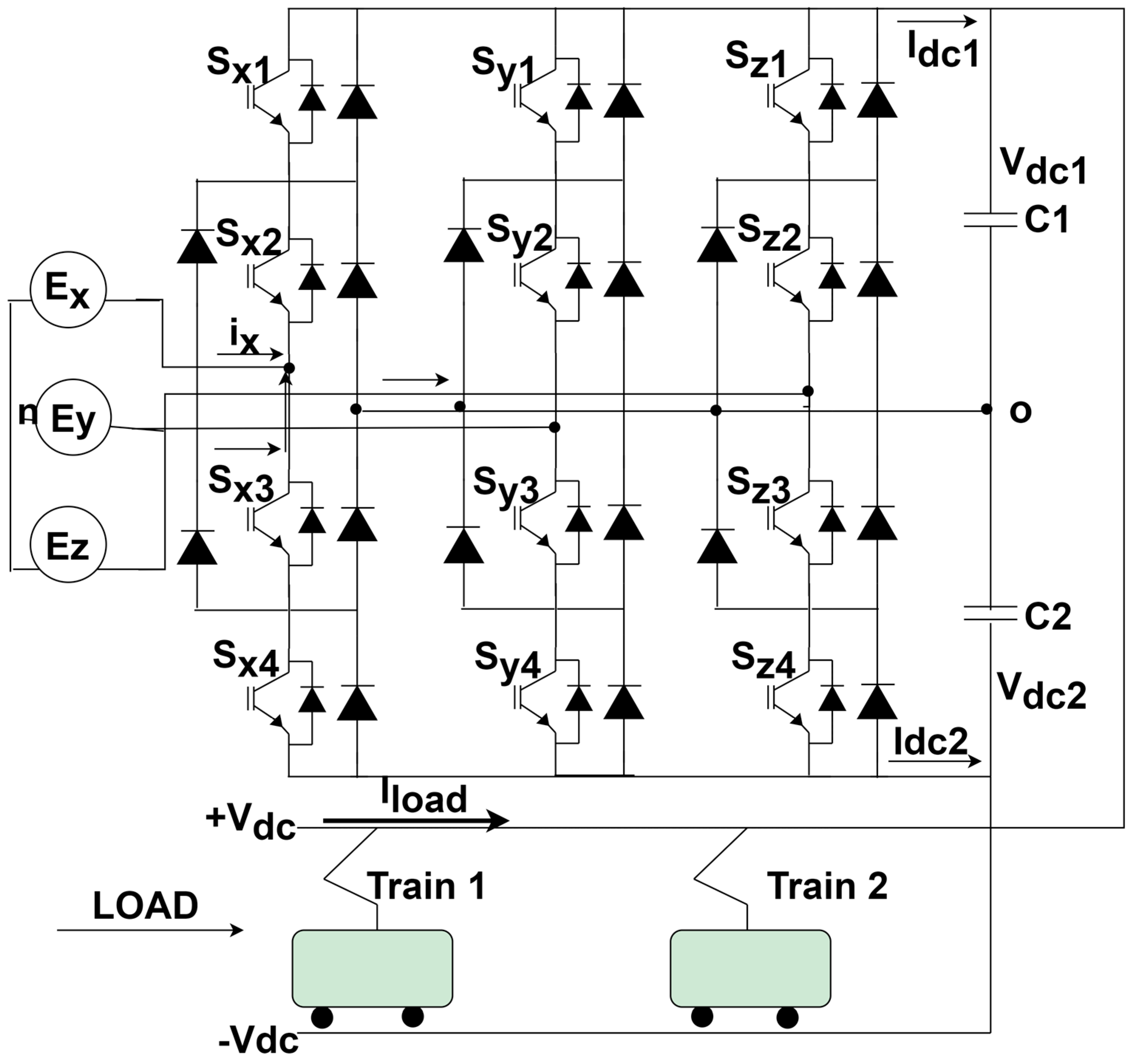
2. AC-DC Bi-Directional NPC Topology

System Configuration

A three-level NPC inverter is an appropriate topology for usage in high- and medium-power systems, as was stated in the Introduction. The NPC inverter’s three-level circuit design is suited for applications in the transportation and industrial fields. There are two switches in each phase of a two-level converter, which is commonly utilized. As a result, one switch must withstand a voltage stress of either +Vdc/2 or −Vdc/2. The NPC’s three-level, three-phase inverter uses four switches and two diodes for each of its three phases. Two switches can therefore equally divide the voltage stress of +Vdc/2 or −Vdc/2, unlike two-level converters. Additionally, the two diodes and two mid switches enable the load to be linked to the NP of the DC link, allowing the three-level NPC inverter to have three voltage levels. As this converter has three voltage levels, the total harmonic distortion (THD) is lower in the three-level inverter than the two-level converter. The NP, however, experiences a current flow when the zero voltage is chosen, which may result in fluctuations in the voltages at the higher and lower capacitors.
A three-level inverter is required, therefore, to regulate both the current and the balance of the upper and lower capacitor voltages. The structure of a three-phase, three-level NPC inverter is depicted in Figure 1. In the Figure 1, the resistor and inductor for each phase is neglected, whereas, if we consider it for each phase, by applying KVL to Figure 1, the equation will become
v g n     i g R g   L g d i g d t   =   v g O   +   v O n       where   ( g = x , y , z )
Adding all the phase equations, we obtain
g = x , y , z v g n     g = x , y , z i g R g     g = x , y , z L g d i g d t   =   g = X , Y , Z v g O   +   g = X , Y , Z   v O n
Assuming that the supply is balanced, we have
g = x , y , z v g n   = 0 ,     g = x , y , z i g   = 0 ,   and   g = x , y , z d i g d t   =   0
Therefore, the three phase equations can be rewritten as
V x n       R i x     L d i x d t   =   2 3 V X O     1 3 V Y O     1 3 V Z O V y n       R i y     L d i y d t   =   2 3 V Y O     1 3 V X O     1 3 V Z O V z n       R i z     L d i z d t   =   2 3 V Z O     1 3 V Y O     1 3 V X O
The voltages at the pole are given in Table 1 for various switching states, whereas the switching algorithm is shown in Table 2 below.
Therefore, the pole voltage of phase X can be written as
V X O   =   U x 1 V d c 1   +   U x 4   V d c 2
The pole voltages for phases Y and Z are similarly provided as follows:
V Y O   =   U y 1 V d c 1   +   U y 4   V d c 2 V Z O   =   U z 1 V d c 1   +   U z 4   V d c 2
The converter’s entire system dynamics equation in state-space representation is as follows:
d i x d t d i y d t d i z d t d V d c 1 d t d V d c 2 d t   =   R L 0 0 1 L ( 2 3 V X 1     1 3 V Y 1     1 3 V Z 1 ) 1 L ( 2 3 V X 4     1 3 V Y 4     1 3 V Z 4 ) 0 R L 0 1 L ( 1 3 V X 1   + 2 3 V Y 1     1 3 V Z 1 ) 1 L ( 1 3 V X 4   +   2 3 V Y 4     1 3 V Z 4 ) 0 0 R L 1 L ( 1 3 V X 1   1 3 V Y 1   +   2 3 V Z 1 ) 1 L ( 1 3 V X 4   1 3 V Y 4   +   2 3 V Z 4 ) U x 1 C 1 U y 1 C 1 U z 1 C 1 1 R L C 1 1 R L C 1 U x 4 C 2 U y 4 C 2 U z 4 C 2 1 R L C 2 1 R L C 2 i x i y i z V d c 1 V d c 2 +   1 L 0 0 0 1 L 0 0 0 1 L   V X V Y v Z
By taking all output state variables, the equation of the output can be written as
w =   1 0 0 0 0 0 1 0 0 0 0 0 1 0 0 0 0 0 1 0 0 0 0 0 1 i x i y i z V d c 1 V d c 2 T
It is clear from (7) and (8) that the switch signals and system parameters affect the converter’s dynamic equations. Thus, the regulation of the switching signals affects the dynamics of the converter as a whole.
By the definition of the space vector, the output voltage equation will be
v =   2 3   ( v x 0   +   α v y 0   +   α 2 v z 0 )
There are 27 switching states for the three-phase NPC converter, which results in 19 distinct voltage vectors. Some of the switching states are redundant and produce the same voltage vector. For one phase of the converter, the switching states are as shown in Table 1.

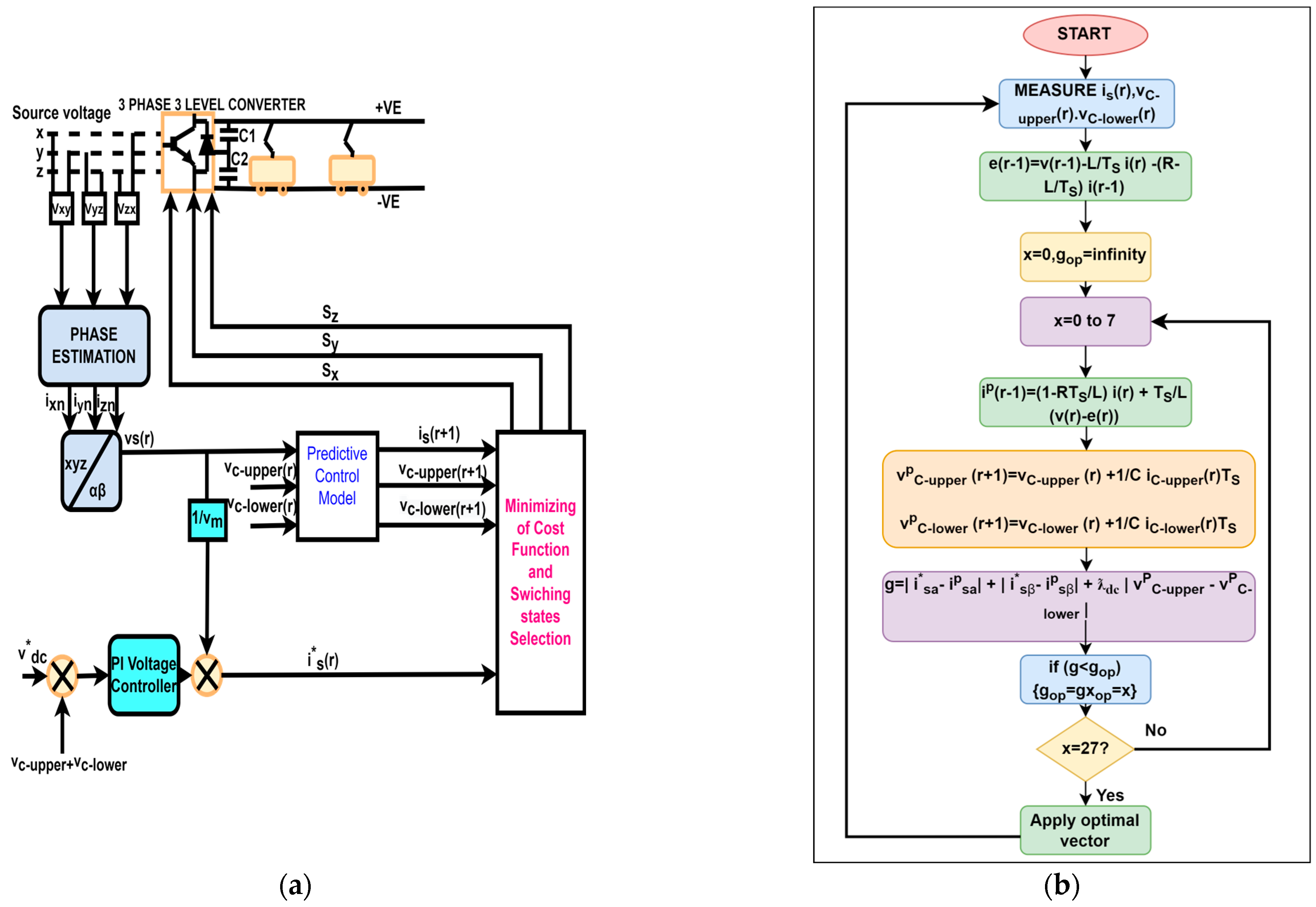
3. Proposed Model Predictive Control Method

3.1. Conventional PI Control Method

A PI controller is required for non-integrating processes, or processes that eventually produce, given the same set of inputs and disturbances, the same output. The proportional–integral controller employs both proportional and integral controller control actions. The shortcomings of each individual controller are eliminated when two different controllers are joined to provide a more efficient controller.
The expression for the PI controller is as follows:
I n   =   K p r o p ( V D C , r e f e r e n c e     V D C   B U S )   +   K i ( V D C , r e f e r e n c e     V D C   B U S )
In the above equation, Kp and Ki are the gains of proportional and integral control for the DC bus bar voltage. The DC link’s bare minimum voltage is required to determine the peak line-neutral voltage, which can be written as
V d c min i m u m   >   V L N ( R M S )   2     3     2.45     V L N ( R M S )

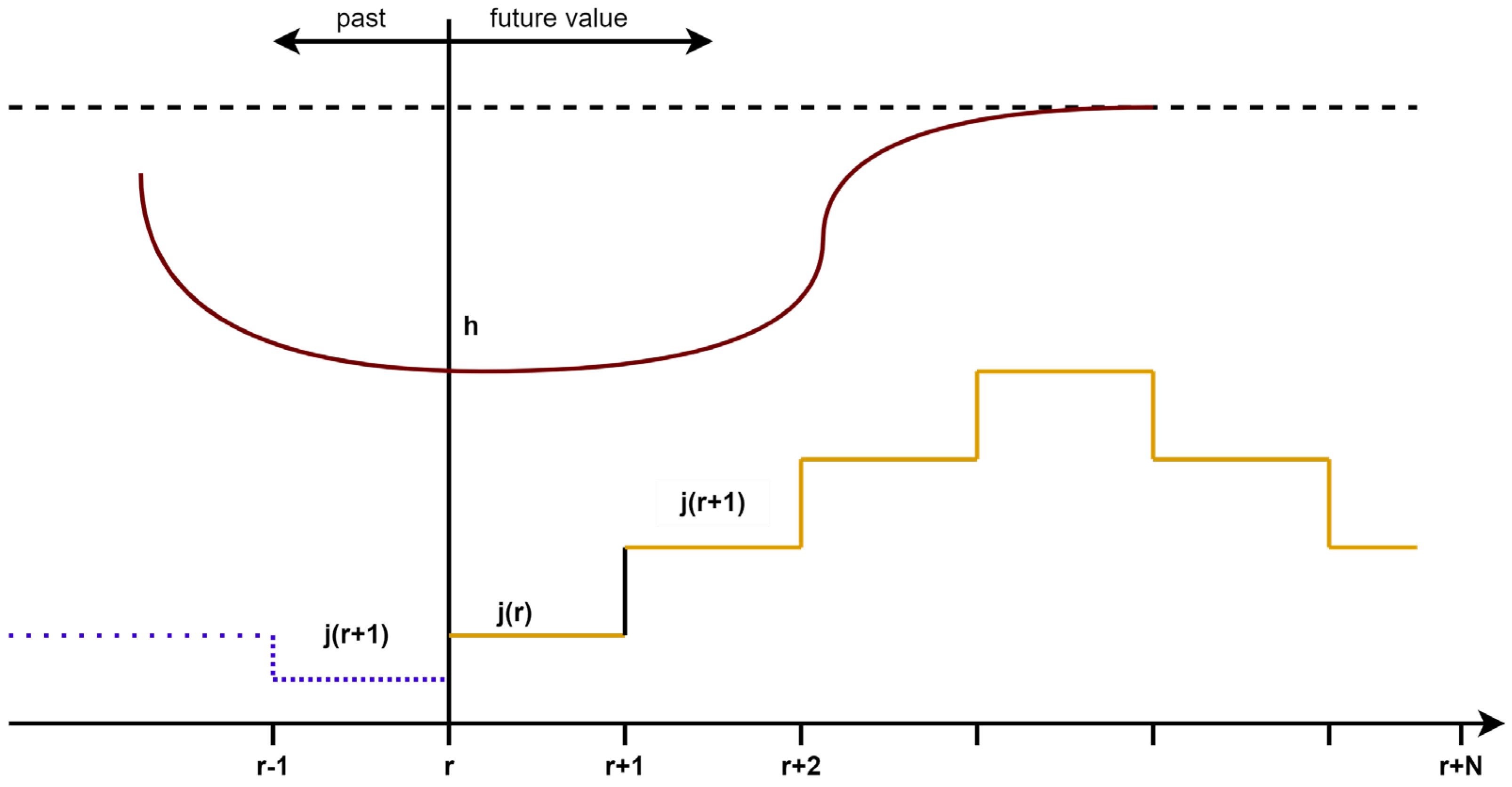
3.2. Model Predictive Controller

MPC is used for the prediction of future values for a complete horizon in time. The cost function should be designed as per the system model, which will represent the system behavior. The best results can be achieved by lowering the cost function. The discrete time model for MPC in the state-space model is expressed as follows:
h ( r + 1 )   =   A   h ( r )   +   B   j ( r ) w ( r )   =   C   w ( r )   +   D   m ( r )
By measuring the data and generating a new set of ideal actuations for every iteration of the optimization challenge, the model can be solved for each sampling instant. The working principle is shown in Figure 2.
The discrete time model is obtained by using the Euler method, for which the expression is as follows:
d h d t   =   h ( r + 1 )   h ( r ) T s
The expression for the load, which allows the future load current to be forecast at time r + 1, is written as
i p ( r + 1 )   =   1   R T s L     i ( r )   +   T s L ( v ( r )   e ( r ) )

3.2.1. Capacitor Voltage Control on Output of Converter

A pair of capacitors are connected in series on the DC link of a three-level NPC, and the capacitor’s neutral point is clamped on each leg by a pair of diodes. When a three-level NPC is in operation, a voltage imbalance between the upper and lower capacitors occurs because the upper and lower capacitors are charged or discharged at different rates due to the three phases’ switching states. When using small vectors, V1–V6 experience this type of voltage unbalancing. As the voltage unbalancing of the DC link capacitor creates distortion in the AC side current, voltage balancing management of the upper and lower capacitor is required.
The capacitor voltage equation for the upper and lower arms at (r + 1) is written as
v c u p p e r ( r + 1 )   =   v c u p p e r   +   1 C   i c u p p e r ( r )   T s v c l o w e r ( r + 1 )   =   v c l o w e r   +   1 C   i c l o w e r ( r )   T s
The switching status of each leg determines the current ic(r) that flows into the DC link capacitor from the three-level NPC AC/DC PWM converter, which is expressed as follows:
i c u p p e r ( r )   =     i d c ( r )     H 1 x i x ( r )     H 1 y i y ( r )     H 1 z i z ( r ) i c l o w e r ( r )   =   i d c ( r )     H 2 x i x ( r )     H 2 y i y ( r )     H 2 z i z ( r )
In Equation (15), Sg1 and Sg2 are determined by the below switching status:
H 1 g   =   1       i f     S g = + v e z e r o             o t h e r w i s e H 2 g   =   1       i f     S g = v e z e r o             o t h e r w i s e f o r   g = x , y , z
The capacitor’s voltage balancing equation can be considered from Equations (14)–(16).

3.2.2. Cost Function

When reducing the current and DC bus voltage error, the predictive current and voltage control shows rapid dynamic characteristics. The absolute difference between the reference current and voltage and the predicted current and voltage must be taken into account by the cost function, which is written as
g   =   i s α     i s α p     +   i s β     i s β p       λ d c   v c u p p e r p     v c l o w e r p
Using this component λ d c   v c u p p e r p     v c l o w e r p , the voltage balance of the three-level NPC DC connection capacitor is managed.
The control flow diagram for the MPC is shown in Figure 3b.

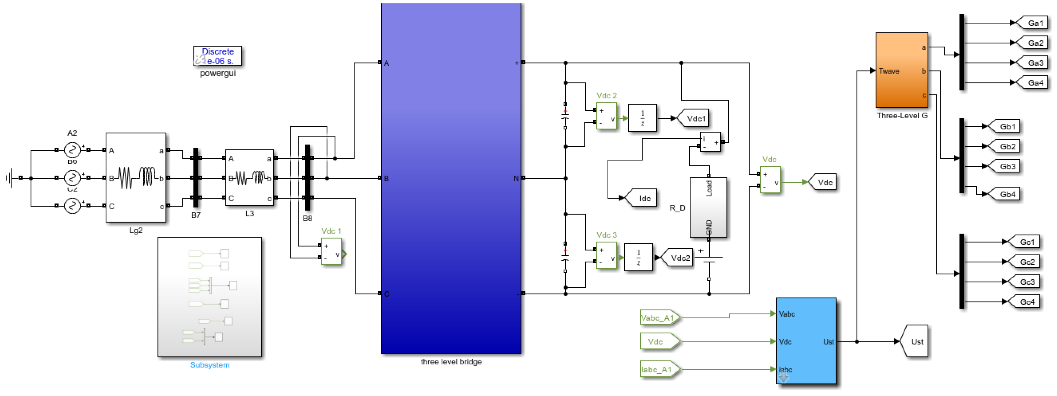
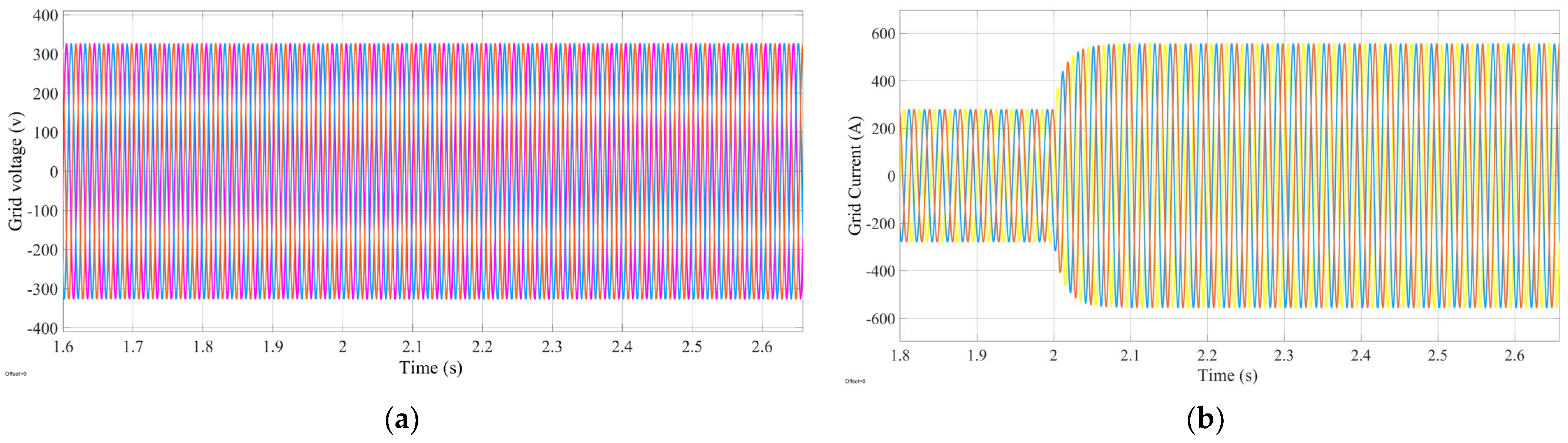
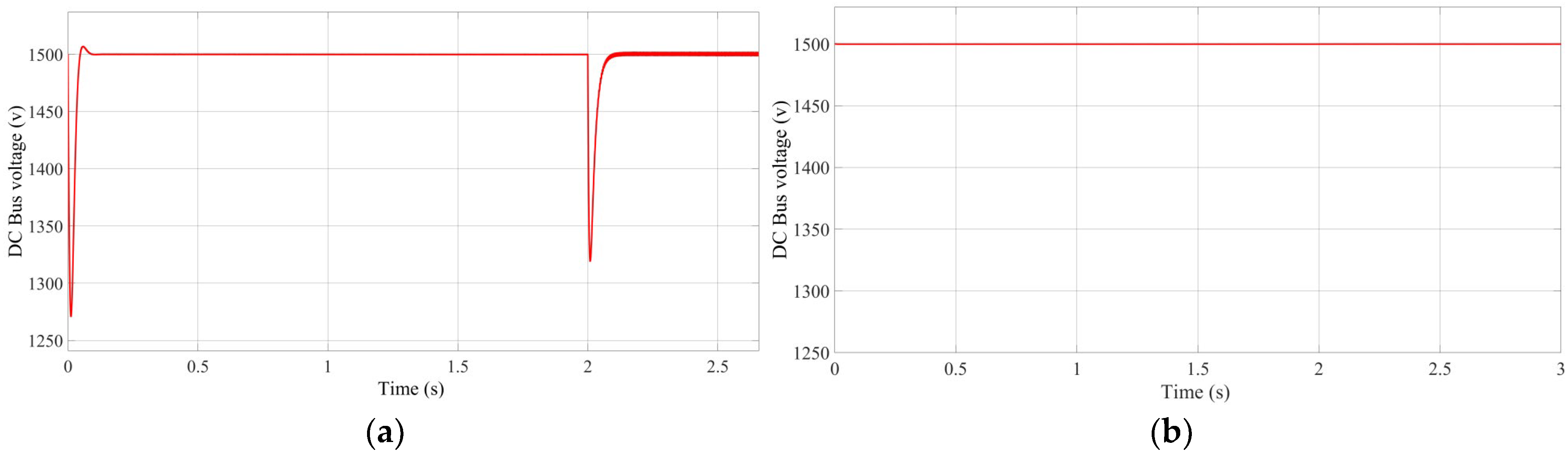
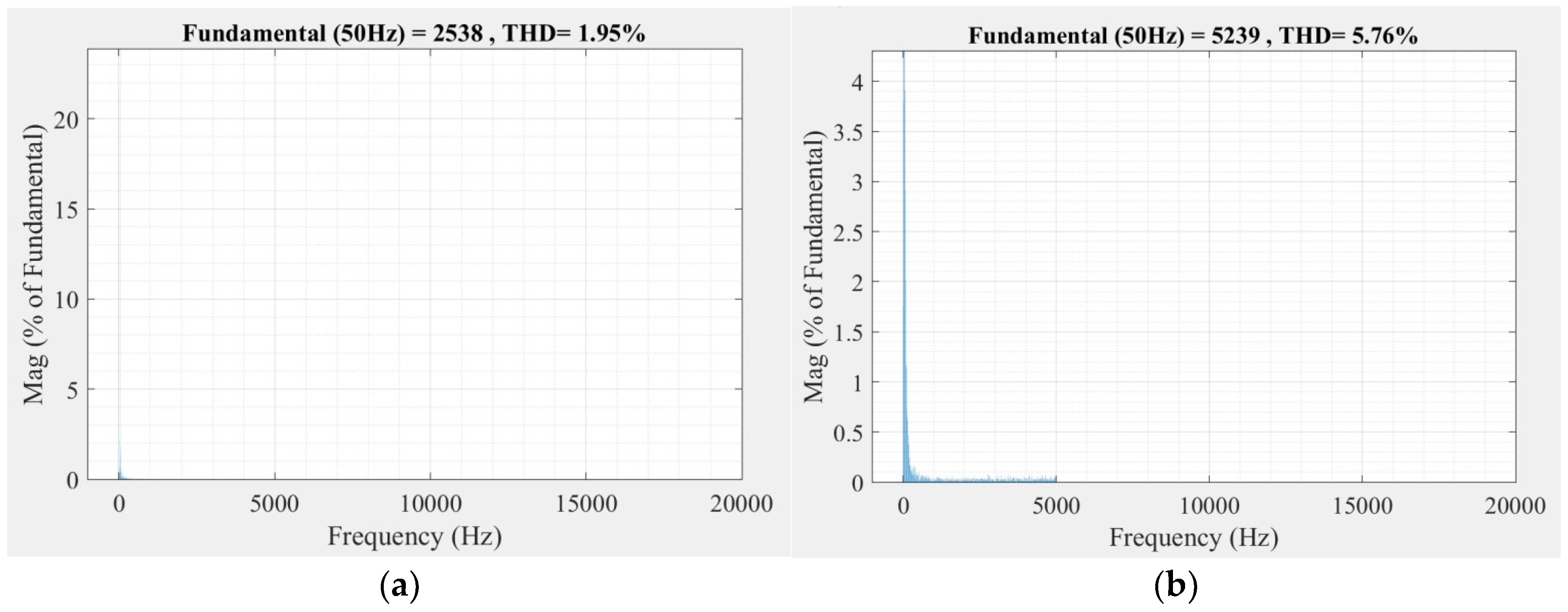
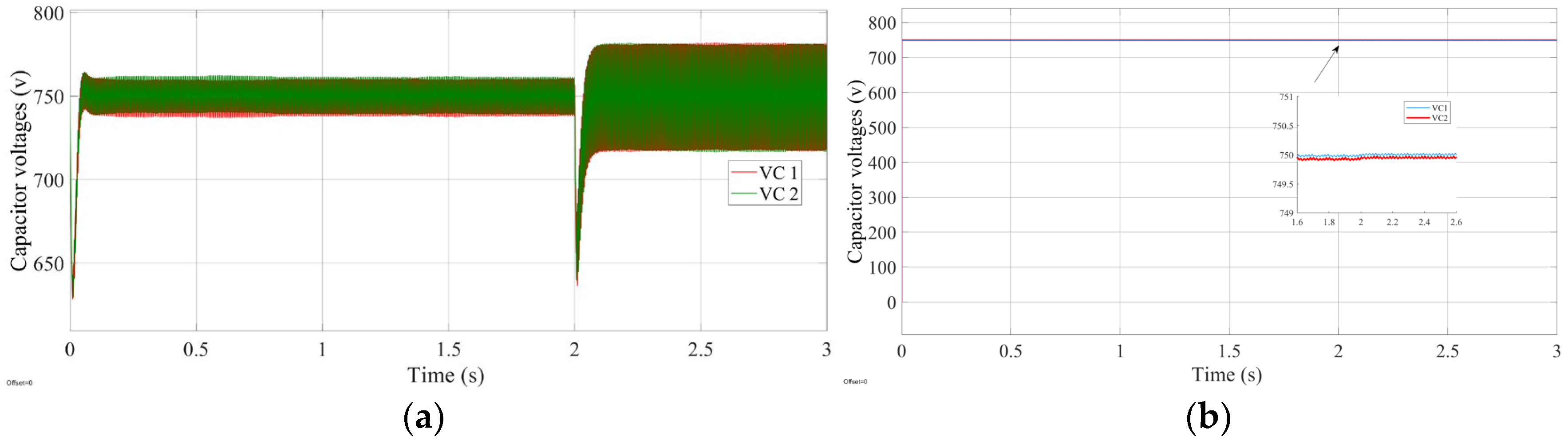
4. Simulation and Discussion

The simulation is performed for variable loads in a subway for both controllers, PI and MPC, with a three-level NPC DC output voltage. As a result, three different voltages, ±750 [VC1-Upper, VC2-Lower], 1500 [Vdc], can be employed. However, in this case, the simulation runs when the load is connected to 1500 [Vdc]. Figure 4 shows the Simulink model of the system, whereas Figure 5a,b shows the grid voltage and current which is applied.
To confirm the effectiveness of the suggested method’s control for variable loads in the DC bus bar of subway, simulations concerning PI control and model predictive current control are conducted under the same conditions.
Figure 6 shows the control responses of the PI and MPC controllers. In Figure 6a, for the PI controller, it is clear that the first load is applied at 0 sec and the peak time is approximately [0.1 s], the rise time is approximately [0.075 s], the overshoot time is approximately [0.025 s] and the settling time is approximately [0.125 s] to become stable at 1500 Vdc in the DC bus bar of the subway. When another load is applied at 2 s, the change in voltage is very large and the voltage abruptly declines to 1320 Vdc; at this position, the peak time is approximately [2.1 s], the rise time is approximately [2.075 s], the overshoot time is approximately [2.025 s] and the settling time is approximately [2.125 s] to become stable at 1500 Vdc in the DC bus bar of the subway, which can harm the system. On the other hand, for MPC, in Figure 6b, with the changing load timings, there is a minor change in voltage for both loads and the response is very good. From the above discussion, it is clear that the MPC response is better than that of the PI controller and the THD is reduced in MPC compared to the PI controller, as shown in Figure 7. Figure 8a,b is showing the capacitors voltage behavior for PI and MPC, where it’s clear that there is too much capacitors voltage fluctuations in capacitors voltage for PI controller and results for MPC is best.

5. Conclusions

This study models a three-level NPC AC/DC converter utilizing an LL filter and implements model predictive control (MPC). Through simulation, the three-level NPC converter’s control performance is confirmed, and the results are compared with those of the PI control method when the MPC method is used for variable loads on the DC bus bar of a subway. Based on the simulation results, the dynamic characteristic performance is enhanced in a transient condition when model predictive control is used in place of a PI current controller. Model predictive current control performs better in balancing the upper and lower capacitor voltages of the NPC.

Author Contributions

M.I. and S.Y. contributed equally to this manuscript. All authors have read and agreed to the published version of the manuscript.

Funding

This work was supported by the National Natural Science Foundation of China under Grant 52177196 and the Sichuan Science and Technology Program under Grant 2021YFH0074.

Institutional Review Board Statement

Not applicable.

Informed Consent Statement

Not applicable.

Data Availability Statement

Not applicable.

Conflicts of Interest

The authors declare no conflict of interest.

References

  1. Cheok, A.D.; Kawamoto, S.; Matsumoto, T.; Obi, H. High power AC/DC converter and DC/AC inverter for high speed train applications. In Proceedings of the 2000 TENCON Proceedings. Intelligent Systems and Technologies for the New Millennium (Cat. No.00CH37119), Kuala Lumpur, Malaysia, 24–27 September 2000; pp. 423–428. [Google Scholar]
  2. Lai, J.-S.; Peng, F.Z. Multilevel converters—A new breed of power converters. IEEE Trans. Ind. Appl. 1996, 32, 509–517. [Google Scholar]
  3. Tian, K.; Wu, B.; Narimani, M.; Xu, D.; Cheng, Z.; Zargari, N.R. A capacitor voltage-balancing method for nested neutral point clamped (NNPC) inverter. IEEE Trans. Power Electron. 2016, 31, 2575–2583. [Google Scholar] [CrossRef]
  4. Gutierrez, B.; Kwak, S. Model predictive control with pre selection technique for reduced calculation burden in modular multilevel converters. IEEE Trans. Power Electron. 2018, 33, 9176–9187. [Google Scholar] [CrossRef]
  5. Bahrami, A.; Narimani, M. A new five-level T-Type nested neutral point clamped (T-NNPC) converter. IEEE Trans. Power Electron. 2019, 34, 10534–10545. [Google Scholar] [CrossRef]
  6. Tan, G.; Deng, Q.; Liu, Z. An optimized SVPWM strategy for fivel evel active NPC (5L-ANPC) converter. IEEE Trans. Power Electron. 2014, 29, 386–395. [Google Scholar] [CrossRef]
  7. Xu, J.; Zhao, C.; Xiong, Y.; Li, C.; Ji, Y.; An, T. Optimal design of MMC levels for electromagnetic transient studies of MMC-HVDC. IEEE Trans. Power Deliv. 2016, 31, 1663–1672. [Google Scholar] [CrossRef]
  8. de Freitas, I.S.; Bandeira, M.M.; Barros, L.D.M.; Jacobina, C.B.; Santos, E.C.D.; Salvadori, F.; da Silva, S.A. A carrier-based PWM technique for capacitor voltage balancing of single-phase three-level neutral-point-clamped converters. IEEE Trans. Ind. Appl. 2015, 51, 3227–3235. [Google Scholar] [CrossRef]
  9. Tallam, R.M.; Naik, R.; Nondahl, T.A. A carrier-based PWM scheme for neutral-point voltage balancing in three-level inverters. IEEE Trans. Ind. Appl. 2005, 41, 1734–1743. [Google Scholar] [CrossRef]
  10. Choi, U.-M.; Lee, H.-H.; Lee, K.-B. Simple neutral-point voltage control for three-level inverters using a discontinuous pulse width modulation. IEEE Trans. Energy Convers. 2013, 28, 434–443. [Google Scholar] [CrossRef]
  11. Wu, W.; Wang, D.; Liu, L. A multi-layer sequential model predictive control of three-phase two-leg seven-level T-type nested neutral point clamped converter without weighting factors. IEEE Access 2019, 7, 162735–162746. [Google Scholar] [CrossRef]
  12. Teichmann, R.; Bernet, S. A comparison of three-level converters versus two-level converters for low-voltage drives, traction, and utility applications. IEEE Trans. Ind. Appl. 2005, 41, 855–865. [Google Scholar] [CrossRef]
Figure 1. Load model of three-φ three-level NPC converter.
Engproc 46 00037 g001
Figure 2. Working principle of MPC.
Engproc 46 00037 g002
Figure 3. Schematic showing (a) MPC block diagram for three-phase three-level NPC; (b) design control flow diagram.
Engproc 46 00037 g003
Figure 4. Proposed system model diagram.
Engproc 46 00037 g004
Figure 5. Schematic showing grid (a) voltage; (b) current.
Engproc 46 00037 g005
Figure 6. The bus bar voltage for variable loads for (a) PI controller; (b) MPC controller.
Engproc 46 00037 g006
Figure 7. FFT analysis of the system for (a) MPC controller; (b) PI controller.
Engproc 46 00037 g007
Figure 8. The upper and lower capacitor voltages (a) for PI controller; (b) for MPC controller.
Engproc 46 00037 g008
Table 1. Pole voltages for various switching states.
SgSg1Sg2Sg3Sg4g0
+veONONOFFOFFVdc/2
zeroOFFONONOFF0
−veOFFOFFONON−Vdc/2
Table 2. Switching algorithm.
Switching SymbolSwitching StatePole Voltage
Ux1Ux4Sx1Sx2Sx3Sx4
10ONONOFFOFFVdc/2
00OFFONONOFF0
01OFFOFFONON−Vdc/2
11ONOFFOFFONFloating
Disclaimer/Publisher’s Note: The statements, opinions and data contained in all publications are solely those of the individual author(s) and contributor(s) and not of MDPI and/or the editor(s). MDPI and/or the editor(s) disclaim responsibility for any injury to people or property resulting from any ideas, methods, instructions or products referred to in the content.

